Sub-section
Type
TECHNICAL NOTE
Edition Anglaise
3239A
Service 0422
77 11 205 445
JUNE 1999
BOSCH 5.3 ABS WITH SPEED INFORMATION FUNCTION
38
• Engine:
XXX
• Gearbox:
XXX
JE0
X
Basic manual
:
N.T.
3034A
3 8
"The repair methods given by the manufacturer in this document are based on the
technical specifications current when it was prepared.
The methods may be modified as a result of changes introduced by the
manufacturer in the production of the various component units and accessories
from which his vehicles are constructed."
All copyrights reserved by Renault.
Copying or translating, in part or in full, of this document or use of the service part
reference numbering system is forbidden without the prior written authority of
Renault.
C
Renault 1999
This note is in addition to Technical Note 3034A.
Contents
Page
BOSCH ABS
Operating principle
Wiring diagram
Wiring diagram key
31 track connector
Tyre circumference
Interchangeability of computer and complete
hydraulic assembly
Fault finding
Introduction
XR25 fiche
Interpretation of XR25 bargraphs
Checking conformity
Aid
Customer complaint
Fault chart
38-1
38-2
38-3
38-4
38-5
38-5
38-6
38-7
38-9
38-10
38-11
38-12
38-13
ELECTRONICALLY CONTROLLED HYDRAULIC
SYSTEMS
38

ELECTRONICALLY CONTROLLED HYDRAULIC SYSTEMS
Bosch ABS
38
The new BOSCH 5.3 ABS computers fitted to the ESPACE provide a vehicle speed signal (this signal replaces
that from the speed sensor located on the gearbox).
OPERATING PRINCIPLE
The ABS computer calculates the vehicle speed from the wheel speed and the tyre circumference in the
memory (see page 38-9).
38-1
ELECTRONICALLY CONTROLLED HYDRAULIC SYSTEMS
Bosch ABS
38
DIM3806-2
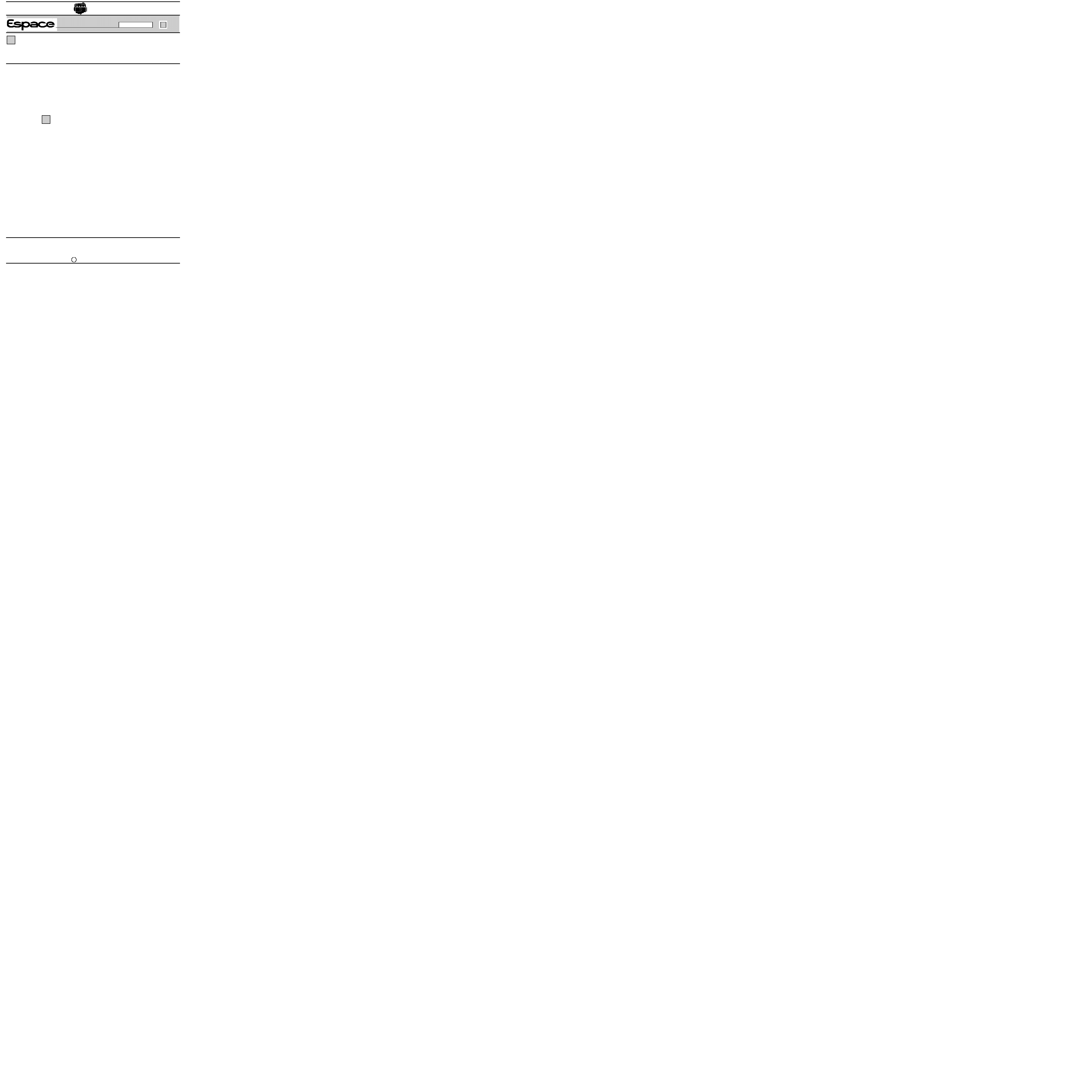
WIRING DIAGRAM
38-2

ELECTRONICALLY CONTROLLED HYDRAULIC SYSTEMS
Bosch ABS
38
WIRING DIAGRAM KEY
104
Ignition switch
120
Injection computer
150
Rear right hand wheel sensor
151
Rear left hand wheel sensor
152
Front right hand wheel sensor
153
Front left hand wheel sensor
160
Stop switch
225
Diagnostic socket
247
Instrument panel
373
Cruise control unit
597
Engine fuse box
645
Passenger compartment connection unit
721
ABS hydraulic assembly and computer
866
Diesel injection computer
1016 Passenger compartment electronic unit
R183 Intermediate connection - engine connection unit /ABS
R262 Connection - passenger compartment- engine compartment
38-3
ELECTRONICALLY CONTROLLED HYDRAULIC SYSTEMS
Bosch ABS
38
DIM3801
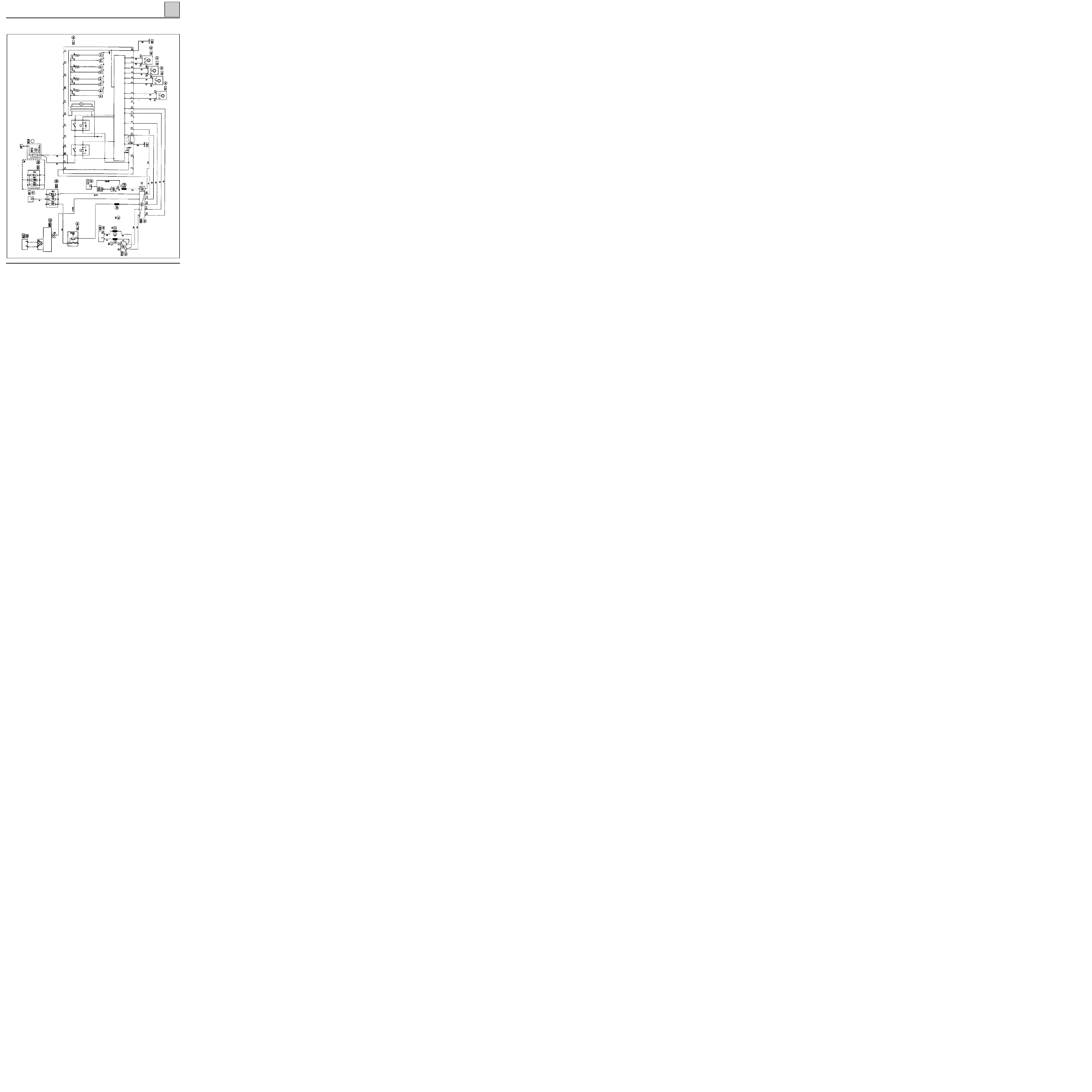
31 TRACK COMPUTER
Track
Description
1
2
3
4
5
6
7
8
9
10
11
12
13
14
RRH sensor earth
Not connected
RRH sensor information
FRH sensor earth
FRH sensor information
FLH sensor earth
FLH sensor information
RLH sensor earth
RLH sensor information
Not connected
Diagnostic line K
Diagnostic line L
Not connected
Stop lights switch information
A Micro-spring connecting to earth (terminal 19) and pin 21 (ABS and
NIVOCODE
warning lights) in case
connector is disconnected.
Allocation of connector tracks
Track
Description
15
16
17
18
19
20
21
22
25
26
27
31
+ after ignition computer feed
Pump motor earth
+ BATT
(solenoid valves and pump
motor)
+ BATT
(solenoid valves and pump
motor)
Electronic earth
Not connected
ABS fault warning light
Vehicle speed information
Not connected
Not connected
Not connected
Not connected
38-4
ELECTRONICALLY CONTROLLED HYDRAULIC SYSTEMS
Bosch ABS
38
The tyre circumference is to be programmed into the memory of the new computer. This is done by entering
the wheel diameter configuration (G30*X*) using the fault finding tool.
TYRES
VALUE TO ENTER ("X")
195/65/15
45
205/65/15
96
215/65/15
147
215/55/16
76
225/55/16
121
Following entering of the value, erase the computer memory then switch off the ignition.
The tachometer value (#30) can be used to check the correct value has been entered.
INTERCHANGEABILITY OF COMPUTER AND COMPLETE HYDRAULIC ASSEMBLY
Since the computers and hydraulic assemblies of the BOSCH 5.3 ABS are mechanically, hydraulically and elec-
trically completely interchangeable, with or without the speed information function, the part numbers have
been unified.
For exchange or repair only computers with the speed information function are fitted, even on vehicles fitted
with the first generation computer as standard (without the speed information function).
When a computer is replaced, when the ignition is switched on, the ABS warning light will flash rapidly to in-
dicate that the tyre circumference has not been programmed. This is used to calculate the vehicle speed (even
if the computer speed information function is not used on the vehicle).
The ABS warning light can be made to stop flashing using the configuration of wheel diameter (G30*X*).
ABS computers with the speed information function are identified by the following computer number (#12)
:
38-5

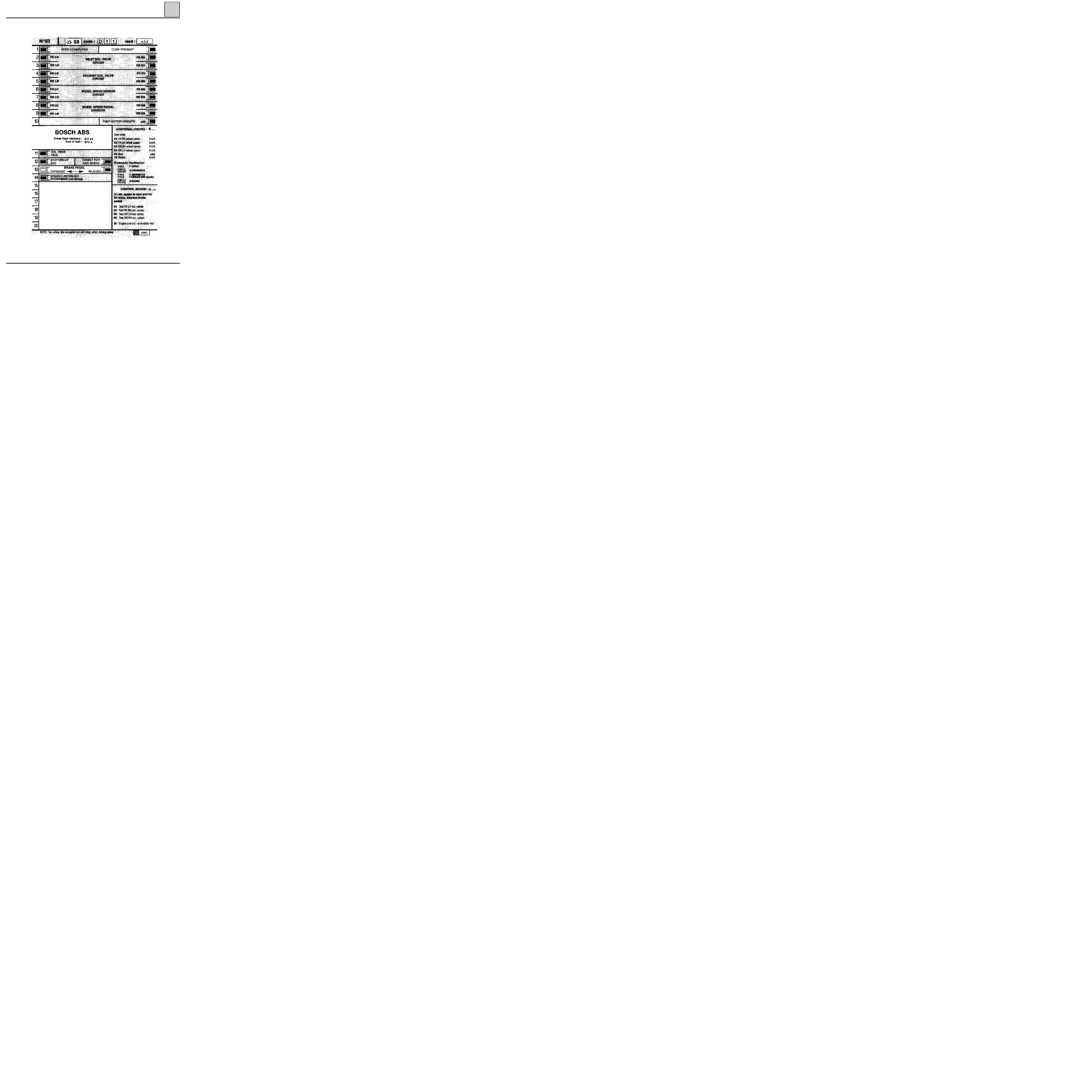
FAULT FINDING - INTRODUCTION
CONDITIONS FOR APPLYING THE CHECKS DEFINED IN THIS FAULT FINDING DOCUMENT
The checks defined in this fault finding document are only to be applied to the vehicle where the title of the
fault dealt with corresponds exactly to the display noted on the fault finding tool.
If a fault is dealt with when the bargraph is flashing, the conditions for confirming the actual presence of the
fault (and the necessity of applying the fault finding) are given in the "Notes" section or at the start of the
interpretation of the bargraph.
If a bargraph is only interpreted in the case where it is permanently illuminated, applying the checks
recommended in the fault finding when the bargraph is flashing will not allow the origin of the memorisation
of the fault to be determined. In this case, only a check of the wiring and connections of the component at
fault may be carried out (the fault is simply memorised as it is not present at the time of checking).
NOTE :
the ignition must be switched off before the fault finding tool is used.
TOOLING REQUIRED FOR OPERATIONS ON THE ABS SYSTEM
Fault finding tools.
Reminders:
When an intermittent fault is memorised, the ABS warning light will illuminate when the vehicle is next used
until a speed equal to 7.5 mph (12 km/h) is reached. When the fault is memorised, a counter associated with the
fault is set to 40. This counter is decreased each time the ignition is switched on if the fault is not present when
the vehicle speed exceeds 7.5mph (12 km/h).
When the counter reaches 1, it is no longer decreased and the fault is not erased.
ELECTRONICALLY CONTROLLED HYDRAULIC SYSTEMS
Bosch ABS
38
38-6
FI21853
ELECTRONICALLY CONTROLLED HYDRAULIC SYSTEMS
Bosch ABS
38
FAULT FINDING - XR25 FICHE
38-7

FAULT FINDING - XR25 FICHE
BARGRAPH SYMBOLS
FAULTS
(always on a coloured background)
If illuminated, this indicates a fault on the product tested. The associated text
defines the fault.
The bargraph may be :
- Permanently illuminated
: fault present.
- Flashing
: fault memorised.
- Extinguished
: no fault or fault not found.
STATUS
(always on a white background)
Bargraph always at the top right hand side.
If illuminated dialogue has been established with the computer for the product.
If it remains extinguished:
- The code does not exist.
- There is a fault with the tool, the computer or the XR25 / computer connection.
The representation of the following bargraphs indicates their initial status:
Initial status: (ignition on, engine stopped, no operator action)
Indefinite
illuminated when the function or condition on
the fiche is met.
Extinguished
Illuminated
extinguishes when the function or condition
specified on the fiche is no longer being met.
ADDITIONAL NOTES
Certain bargraphs have a *. The *.. command, when the bargraph is illuminated,
allows additional information on the type of fault or status to be displayed.
or
ELECTRONICALLY CONTROLLED HYDRAULIC SYSTEMS
Bosch ABS
38
38-8
Erase the computer memory (G0**).
Carry out another check using the fault finding tool.
AFTER REPAIR
The
BOSCH 5.3
ABS computer with "speed information" function is capable of providing a vehicle speed
signal to all the users of this information in the vehicle (engine management, passenger compartment
connection unit,...).
This vehicle speed signal will replace that currently supplied by the speed sensor on the gearbox.
The ABS computer calculates the vehicle speed from the wheel speeds and the circumference of the tyres
fitted to the vehicle.
The tyre circumference is to be programmed into the memory of the new computer. This is done by ente-
ring the wheel diameter configuration (G30*X*) using the fault finding tool.
TYRES
VALUE TO ENTER ("X")
195/65/15
45
205/65/15
96
215/65/15
147
215/55/16
76
225/55/16
121
Following entering of the value, erase the computer memory then switch off the ignition.
The tachometer value (#30) can be used to check the correct value has been entered.
ELECTRONICALLY CONTROLLED HYDRAULIC SYSTEMS
Bosch ABS
38
NOTES
None.
14
Bargraph 14 LH side
Speed information programming
38-9
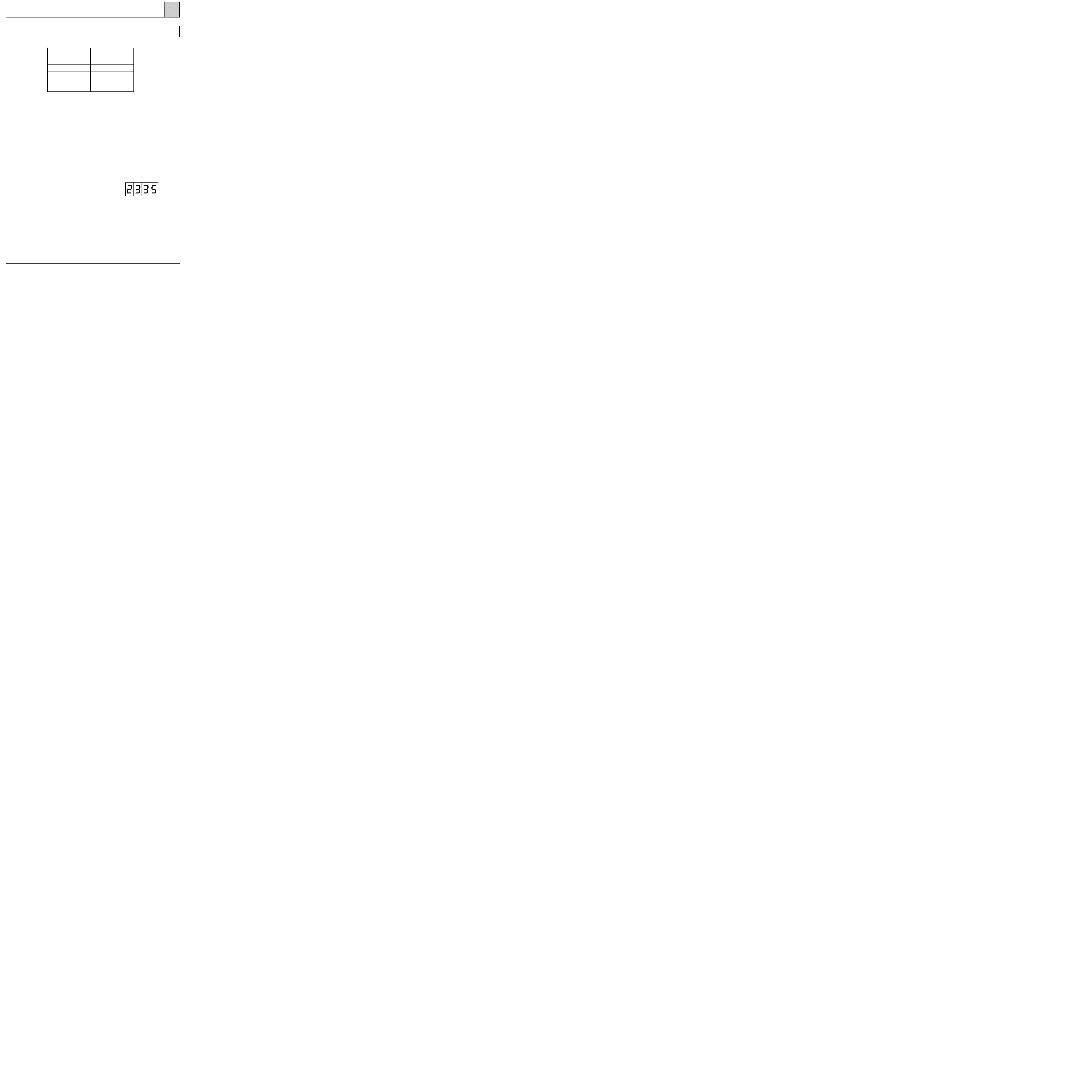
Order
Function
Title
Display and notes
Diagnostic
1
Battery
voltage
Parameter (#06) : Computer
feed voltage
11.6 <X< 13.2 V
If there is a fault, refer
to the fault finding for
this parameter
2
Computer
conformity
Parameter (#12) : Computer
number
233.5
None
3
Reading the
value
Parameter (#30) : Speed
information value
45
47
96
76
121
45 = 195/65/15
47 = 215/65/15
96 = 205/65/15
76 = 215/55/16
121 = 225/55/16
ELECTRONICALLY CONTROLLED HYDRAULIC SYSTEMS
Bosch ABS
38
NOTES
None
FAULT FINDING - CHECKING CONFORMITY
38-10

Using the commands:
Operating the solenoid valves for a hydraulic test:
Lift the vehicle to check that the wheels turn freely.
Hold the brake pedal down to prevent the wheel to be tested from turning if it is turned by hand (do
not brake too hard so that you are at the releasing limit).
Use the wheel solenoid valve command (G0X*)
The wheel concerned should lock / re-
lease ten times.
Operating the pump motor:
Use the pump motor test command (G08*)
The motor should operate
and press the brake pedal
for 2 seconds.
Operating the pump motor and the solenoid valves:
Execute the static actuator test (G020*)
The motor and the solenoid valves
and press the brake pedal
should operate briefly.
Bleeding the hydraulic circuits:
Follow the procedure described in the section "Bleeding the circuits" in N.T. 3034A.
Replacing the computer:
The
BOSCH 5.3
ABS computer with "speed information" function is capable of providing a vehicle speed si-
gnal to all the users of this information in the vehicle (engine management, passenger compartment
connection unit, ...).
This vehicle speed signal will replace that currently supplied by the speed sensor on the gearbox.
The ABS computer calculates the vehicle speed from the wheel speeds and the circumference of the tyres
fitted to the vehicle.
The tyre circumference is to be programmed into the memory of the new computer. This is done by ente-
ring the wheel diameter configuration (G30*X*) using the fault finding tool.
Following entering of the value, erase the computer memory then switch off the ignition.
The tachometer value (#30) can be used to check the correct value has been entered.
TYRES
VALUE TO ENTER ("X")
195/65/15
45
205/65/15
96
215/65/15
147
215/55/16
76
225/55/16
121
ELECTRONICALLY CONTROLLED HYDRAULIC SYSTEMS
Bosch ABS
38
38-11
FAULTS NOTED IN OPERATION OF THE WARNING LIGHT
No vehicle speed information on the instrument panel.
Chart 1
Only refer to this customer complaint after a complete check using the fault
finding tool.
NOTES
ELECTRONICALLY CONTROLLED HYDRAULIC SYSTEMS
Bosch ABS
38
FAULT FINDING - CUSTOMER COMPLAINT
38-12
ELECTRONICALLY CONTROLLED HYDRAULIC SYSTEMS
Bosch ABS
Check using the fault finding tool for the presence or absence of vehicle speed information on the other
systems which use the signal from the ABS computer (engine management, passenger compartment
connection unit,...).
• If the instrument panel is the only system not receiving the signal, ensure the continuity of the connec-
tion between track 22 on the ABS computer and track 17 on the blue 26 track connector (F) for the pas-
senger compartment connection unit.
• If no system is receiving the signal, look for a continuity or insulation fault on the connection between
track 22 on the ABS computer connector and the various users of the vehicle speed information or an in-
ternal fault in one of the signal user systems (proceed by making successive disconnections).
AFTER REPAIR
Carry out a road test then a check with the fault finding tool.
Only refer to this customer complaint after a complete check using the fault
finding tool.
NOTES
38
If the fault persists after these checks, replace the ABS computer.
FAULT FINDING - FAULT CHART
Chart 1
NO VEHICLE SPEED INFORMATION ON THE INSTRUMENT
PANEL
(COMPUTER WITH SPEED INFORMATION FUNCTION)
38-13
Document Outline
Wyszukiwarka
Podobne podstrony:
Identyfikacja systemu informacyjnego w przedsiębiorstwie Speed Trans
techniki informacyjne
wykład 6 instrukcje i informacje zwrotne
Technologia informacji i komunikacji w nowoczesnej szkole
Państwa Ogólne informacje
Fizyka 0 wyklad organizacyjny Informatyka Wrzesien 30 2012
informacja w pracy biurowej 3
Wykorzystanie modelu procesow w projektowaniu systemow informatycznych
OK W2 System informacyjny i informatyczny
Sem II Transport, Podstawy Informatyki Wykład XXI Object Pascal Komponenty
RCKiK LEKARZE STAŻYŚCI (materiały informacyjne)
AUSTRIA PREZENTACJA POWERPOINT (INFORMACJE)
SYSTEMY INFORMATYCZNE ORGANIZACJI WIRTUALNEJ1
Metodyka punktow wezlowych w realizacji systemu informatycznego
Informatyka1 2a1
więcej podobnych podstron