CELLAR
T H E M A G A Z I N E F O R C O M P U T E R A P P L I C A T I O N S
www.circuitcellar.com
CIRCUIT
®
# 12 0 J U LY 2 0 0 0
ROBOTICS
The Next Step
for Stiquito
PIC-SERVO
Motor Control
Robots That
Beat the Heat
Portable
115 VAC Power

2
Issue 120 July 2000
CIRCUIT CELLAR
®
www.circuitcellar.com
— COLUMNS —
Lessons from the Trenches
A Primer for Product Testing
George Martin
Although he admits that product testing isn’t exactly the
most exciting area of engineering, George makes it inter-
esting by covering the basics and then opens the doors of
communication by inviting you to write to him with
your testing issues.
Silicon Update Online
News Flash! Motorola Reorganizes!
Tom Cantrell
We all know that old news is really no news at all, and
when it comes to a company reorganizing, well…. In
this article, Tom takes a look at Motorola and shows us
why it’s so important to do away with the old and bring
in the new.
Double your technical pleasure each month. After you read
Circuit Cellar magazine, get a
second shot of engineering adrenaline with
Circuit Cellar Online, hosted by ChipCenter.
— FEATURES —
Debunking Engineering Myths
Robert Kondner
Robert takes us through several areas of engineering
that people often have misconceptions about. He di-
vides the black-and-white from the gray and shows us
that engineering and engineering management should
not be mistaken as the same.
Using an Expert System
Armin Eberlein, Dale Fukami
& Wonh Chieh Lam
These guys show us the benefit of using an expert
system for applying advanced techniques to system
design and the steps they took in discovering the ad-
vantage of using this tool in both the expert system
and software communities.
Developing an AC Current Generator
Aubrey Kagan & Ernesto Gradin
Although it took them a long time with many stops
and starts and even an integrated circuit going obsolete
in the process, Aubrey and Ernesto take us through the
ins and outs of an AC current generator and show us
that it was definitely worth the wait.
A Practical Guide to TCP/IP Protocols
Tracy Thomas
Tracy gives us a brief introduction to some of the
issues involved in using TCP/IP protocols and
tells us what information is most often
misunderstood by programmers
who are new to the
networking
world.
Table of Contents for June 2000
WWW
.
CIRCUITCELLAR
.
COM
/
ONLINE
THE ENGINEERS
TECH-HELP RESOURCE
Let us help keep your project on track
or simplify your design decision. Put
your tough technical questions to the
ASK US team.
The ASK US research staff of engineers has been
assembled to share expertise with others. The forum
is a place where engineers can congregate to get
some tough questions answered, or just browse
through the archived Q&A’s to broaden their own
intelligence base.
Now Available....
Circuit Cellar Online 1999 issues will be available on CD.
The CD will contain all the online files, the PDF files and
any referenced code files for issues July 1999
through December 1999.
Also on the CD are the Embed-
ded Internet Workshop files
from years 1998 and 1999.
Resource Links
• Speech Synthesis
Bob Paddock
• Unmanned Robotics Competitions
Rick Prescott
Test Your EQ
8 Additional Questions

CIRCUIT CELLAR
®
Issue 120 July 2000
3
www.circuitcellar.com
E
MBEDDED
PC
Applied PCs
Calling for Backup
The Value and Methods of Backing Up
Fred Eady
ISSUE
INSIDE
BEAMStiquito—A Simple Circuit for an Inexpensive Robot
James M. Conrad
Beating the Heat—2000 Trinity College Fire Fighting Home Robot Contest
Rob Walker
USB Chip Choices—Finding A Peripheral Controller
Jan Axelson
Back To BasicX—Part 2: NetSnoop Application
Brian Millier
115 VAC, to Go, Please—Drive a Portable Inverter with a PIC16C54
Tom Napier
Quick and Easy Motor Control—Implementing a PIC-SERVO Controller
Alan Kilian
Embedded Living
Two Ports in a PIC—A Communication Thermostat
Mike Baptiste
Op-Amp Specifications—Part 4: AC Applications
Joe DiBartolomeo
From the Bench
DFPs: Riding the Wave of the Future
Jeff Bachiochi
Silicon Update
Swiss Army Chip
Programmable System Devices
Tom Cantrell
120
120

6
Issue 120 July 2000
CIRCUIT CELLAR
®
www.circuitcellar.com
TASK
MANAGER
EDITORIAL DIRECTOR/PUBLISHER
Steve Ciarcia
MANAGING EDITOR
Rob Walker
TECHNICAL EDITORS
Jennifer Belmonte
Rachel Hill
Jennifer Huber
WEST COAST EDITOR
Tom Cantrell
CONTRIBUTING EDITORS
Mike Baptiste
Ingo Cyliax
Fred Eady George Martin
George Novacek
NEW PRODUCTS EDITOR
Harv Weiner
PROJECT EDITORS
Steve Bedford
Janice Hughes
James Soussounis
David Tweed
ASSOCIATE PUBLISHER
Sue Skolnick
CHIEF FINANCIAL OFFICER
Jeannette Ciarcia
CUSTOMER SERVICE
Elaine Johnston
ART DIRECTOR
KC Zienka
GRAPHIC DESIGNERS
Melissa Clukey
Mary Turek
STAFF ENGINEERS
Jeff Bachiochi
Anthony Capasso
QUIZ MASTER
David Tweed
EDITORIAL ADVISORY BOARD
Ingo Cyliax
Norman Jackson
David Prutchi
Cover photograph Ron Meadows—Meadows Marketing
PRINTED IN THE UNITED STATES
For information on authorized reprints of articles,
contact Jeannette Ciarcia (860) 875-2199 or e-mail jciarcia@circuitcellar.com.
CONTACTING CIRCUIT CELLAR
SUBSCRIPTIONS:
INFORMATION: www.circuitcellar.com or subscribe@circuitcellar.com
TO SUBSCRIBE: (800) 269-6301, www.circuitcellar.com/subscribe.htm, or subscribe@circuitcellar.com
PROBLEMS: subscribe@circuitcellar.com
GENERAL INFORMATION:
TELEPHONE: (860) 875-2199 FAX: (860) 871-0411
INTERNET: info@circuitcellar.com, editor@circuitcellar.com, or www.circuitcellar.com
EDITORIAL OFFICES: Editor, Circuit Cellar, 4 Park St., Vernon, CT 06066
AUTHOR CONTACT:
E-MAIL: Author addresses (when available) included at the end of each article.
CIRCUIT CELLAR
®
, THE MAGAZINE FOR COMPUTER APPLICATIONS (ISSN 1528-0608) and Circuit Cellar Online are published
monthly by Circuit Cellar Incorporated, 4 Park Street, Suite 20, Vernon, CT 06066 (860) 875-2751. Periodical rates paid at Vernon,
CT and additional offices. One-year (12 issues) subscription rate USA and possessions $21.95, Canada/Mexico $31.95, all
other countries $49.95. Two-year (24 issues) subscription rate USA and possessions $39, Canada/Mexico $55, all other
countries $85. All subscription orders payable in U.S. funds only via VISA, MasterCard, international postal money order, or check
drawn on U.S. bank.
Direct subscription orders and subscription-related questions to Circuit Cellar Subscriptions, P.O. Box 5650, Hanover, NH
03755-5650 or call (800) 269-6301.
Postmaster: Send address changes to Circuit Cellar, Circulation Dept., P.O. Box 5650, Hanover, NH 03755-5650.
ADVERTISING
ADVERTISING SALES REPRESENTATIVE
Kevin Dows
Fax: (860) 871-0411
(860) 872-3064
E-mail: kevin.dows@circuitcellar.com
ADVERTISING COORDINATOR
Valerie Luster
Fax: (860) 871-0411
(860) 875-2199
E-mail: val.luster@circuitcellar.com
ADVERTISING CLERK
Sally Collins
rob.walker@circuitcellar.com
Lend Me Your...
c
oming up with the ideas for our “beautiful
issue covers” (as described by one reader) are
one of the interesting challenges of putting each
month’s issue together. The process of coming up with
cover ideas usually requires a couple of editors, graphic designers, and
engineers sitting around the table trying to figure out how to illustrate
themes. (After all, how do you take a picture of fuzzy logic?) The next
step in coming up with cover ideas usually involves a lot of eye-rolling
and “Not while I’m the publisher” feedback from Steve.
Those of you who have read Circuit Cellar for any amount of time might
think we have a back lot full of cover props, but it’s not that easy. Once
we settle on an idea, it’s off to attics, basements, and garages (those of
friends, neighbors, and relatives not excluded) to find what we need.
Right about the time we were discussing cover ideas for this issue,
Jeff Bachiochi was in the process of resurrecting an older wheeled robot
that he had purchased over the Internet. Trips to the copier became
much more interesting with the 2
′
tall rolling creation poised to burst into
a slightly garbled version of “God Bless America” as it slowly bumped its
way around the room, but I felt that it just wasn’t the look we needed in a
cover model. So, I contacted Jake Mendelssohn, the contest administra-
tor for the Trinity College Fire Fighting Home Robot contest to see if he
had any leads.
One of the links he sent me was to a page that had a picture of MAX
dV, which was an entry in this year’s contest at Trinity. Who needs crash-
ing surf and bikinis—this was cover material! A week later I was walking
in the door at Dimensional Control, Inc. (one look at the robot and you
might have guessed that they specialize in CNC machine tools) to talk to
Marc Warren about borrowing MAX dV for a cover shoot.
I’ve seen people who were more willing to part with their children than
they would be to part with a project like MAX dV, but Marc set the robot
in a box, informed me that MAX was powerful and heavy enough to hurt
an inexperienced operator (or innocent bystanders, for that matter), and
told me to call him when we were done.
If there’s one thing I enjoyed the most about putting together this
issue, it was getting to work with some great people who are involved in
the Robotics community. All of the contributors for the “Beating the Heat”
section of the magazine were extremely helpful and cooperative. If space
had permitted I would have gladly included the dozens of URLs that
contain more detailed info on their projects and others, but if you are
interested in contacting them, feel free to drop me a note and I can pass
your comments along to them.
As for this month’s cover, thanks to DCI and Marc Warren
(marc.warren@snet.net) for making it easy and eye-catching.
Circuit Cellar® makes no warranties and assumes no responsibility or liability of any kind for errors in these programs or schematics or for the
consequences of any such errors. Furthermore, because of possible variation in the quality and condition of materials and workmanship of reader-
assembled projects, Circuit Cellar® disclaims any responsibility for the safe and proper function of reader-assembled projects based upon or from
plans, descriptions, or information published by Circuit Cellar®.
The information provided by Circuit Cellar® is for educational purposes. Circuit Cellar® makes no claims or warrants that readers have a right to build
things based upon these ideas under patent or other relevant intellectual property law in their jurisdiction, or that readers have a right to construct or
operate any of the devices described herein under the relevant patent or other intellectual property law of the reader’s jurisdiction. The reader
assumes any risk of infringement liability for constructing or operating such devices.
Entire contents copyright © 2000 by Circuit Cellar Incorporated. All rights reserved. Circuit Cellar and Circuit Cellar INK are registered trademarks of
Circuit Cellar Inc. Reproduction of this publication in whole or in part without written consent from Circuit Cellar Inc. is prohibited.

8
Issue 120 July 2000
CIRCUIT CELLAR
®
www.circuitcellar.com
NEW PRODUCT
NEWS
Edited by Harv Weiner
Serial I/O Cards
Sealevel Systems introduced
a new family of PCMCIA se-
rial I/O cards that provide a
single asynchronous link to
modems, terminals, printers,
or other data collection de-
vices. The PC-SIO-232 card is
designed for applications re-
quiring RS-232 compatibility
and data rates up to 460 kbps
when used with optional en-
hanced UARTs. The ULTRA
PC-SIO-485 takes advantage of
the noise-resistant RS-530/-
422/-485 line to connect to
peripherals (up to 5000 ft). It
can handle the low-level RS-
485 driver maintenance auto-
matically, making
communications driver re-
placement unnecessary. Initial
development can be targeted
for RS-232, debugged, tested,
and then implemented as S485 with little or
no programming changes.
Sealevel includes SeaCOM and WinSSD, a
comprehensive suite of software for the
PCMCIA cards. SeaCOM takes control of
features not available in the standard Win-
dows serial driver such as enhanced UART
support for 16650, 16750, 16850, and 16950
UARTs, RTS enable, and interrupt sharing
capabilities. WinSSD is a comprehensive
diagnostic utility for Windows
95/98 and NT. WinSSD allows
the user to verify the board
IRQ and address settings,
modify the default UART
parameters, perform internal
and external loop back tests,
toggle modem control signals,
and transmit test pattern
messages. WinSSD also allows
terminal mode operations, bit
error rate testing (BERT), and
throughput monitoring.
The PC-SIO-232, and UL-
TRA PC-SIO-485, support
data rates up to 115 kbps and
cost $199 each. Versions that
support 460 kbps are available.
Sealevel Systems Incorporated
(864) 843-4343
Fax: (864) 843-3067
www.sealevel.com
CIRCUIT CELLAR
®
Issue 120 July 2000
9
www.circuitcellar.com
NEW PRODUCT
NEWS
MOTION CONTROLLER
The Model 5954 motion controller provides four axes
of stepper control for PC/104-based systems. It features
a PMD 1451A DSP with a custom Tech80 I/O chip to
provide 1.5-MHz maximum step rate per axis. The DSP
generates S-curve and other stepper profiles to control
position, acceleration, velocity, and jerk. The Model
5954 offers automatic alerts of profile failures.
A 1.25-MHz incremental encoder input per axis pro-
vides position feedback and on-the-fly stall detection.
The controller uses encoders to cross-reference the ac-
tual versus desired position with a tolerance window
that you set for stall detection. Read status or interrupts
can be generated on stalls. The hardware is fully soft-
ware configurable, eliminating the need for jumpers or
potentiometers.
The Model 5954 is rugged. High-speed clamping
diodes provide extended transient protection against
external spiking and noise. Extensive current limiting
resistors harden its hardware for industrial environ-
ments. For greater ease in application development, the
5954’s hardware is software configurable (all functions
stored in nonvolatile memory), eliminating potentiom-
eters, jumpers, and the extra setup time and errors asso-
ciated with them. Sixteen-bit and 32-bit libraries with
C and Visual Basic examples are provided. Unit pricing
begins at $850.
Technology 80 Inc.
(612) 542-9545
Fax: (612) 542-9785
www.tech80.com

10
Issue 120 July 2000
CIRCUIT CELLAR
®
www.circuitcellar.com
BEAMStiquito
FEATURE
ARTICLE
s
With a versatile and
practical design such
as the Stiquito, it’s
hard to keep it from
evolving into more
advanced forms. This
time, James and
Mark have taken the
Stiquito and applied
concepts that provide
a higher survival rat-
ing for robots.
tiquito is a
small, six-legged
hexapod robot. Uni-
versity faculty, univer-
sity and secondary school students,
and hobbyists of all ages have used it
since 1992. Stiquito is unique because
it is inexpensive and its applications
are almost limitless (see Photo 1).
Jonathan Mills of Indiana Univer-
sity developed Stiquito for his re-
search and discovered that its
applications would be easily adaptable
to benefit the education process. The
Stiquito introduces students to analog
and digital electronics, computer
control, and robotics and can be used
to explain advanced topics such as
subsumption architectures, artificial
intelligence, and advanced computer
architecture.
The IEEE Computer Society Press
published two books, Stiquito: Ad-
vanced Experiments with a Simple
and Inexpensive Robot
[1] and
Stiquito for Beginners: An Introduc-
tion to Robotics.
[2] Both of these
books contain instructions for build-
ing the Stiquito, designing and build-
ing control circuits, and examples of
student projects.
You can build a circuit board that
mounts on a built-and-tested Stiquito
robot and direct the robot to walk in a
tripod gait. This circuit feeds current
to the nitinol on a periodic basis,
which you can adjust, making
Stiquito an autonomous robot. Both
books describe circuits that make
Stiquito walk by itself, and a recent
article by James Conrad and Serge
Caron describes another circuit based
on a 555 timer, a shift register, and a
Darlington transistor array. [3]
Our article describes another
simple circuit that can be used to
control an autonomous Stiquito. The
controller is based on the BEAM (Biol-
ogy Electronics Aesthetics Mechanics)
model of simple circuits created by
Mark Tilden of Los Alamos Labs.
BEAM
BEAM is a concept of building
robots that have a high survival rat-
ing. These robots often are self-sus-
taining—they use solar energy and
minimize power consumption. Com-
mon BEAM robots are Photovores,
Solarollers, and Walkers. [5] Most
look like insects.
Characteristics of the Stiquito
include few parts and a flexible cir-
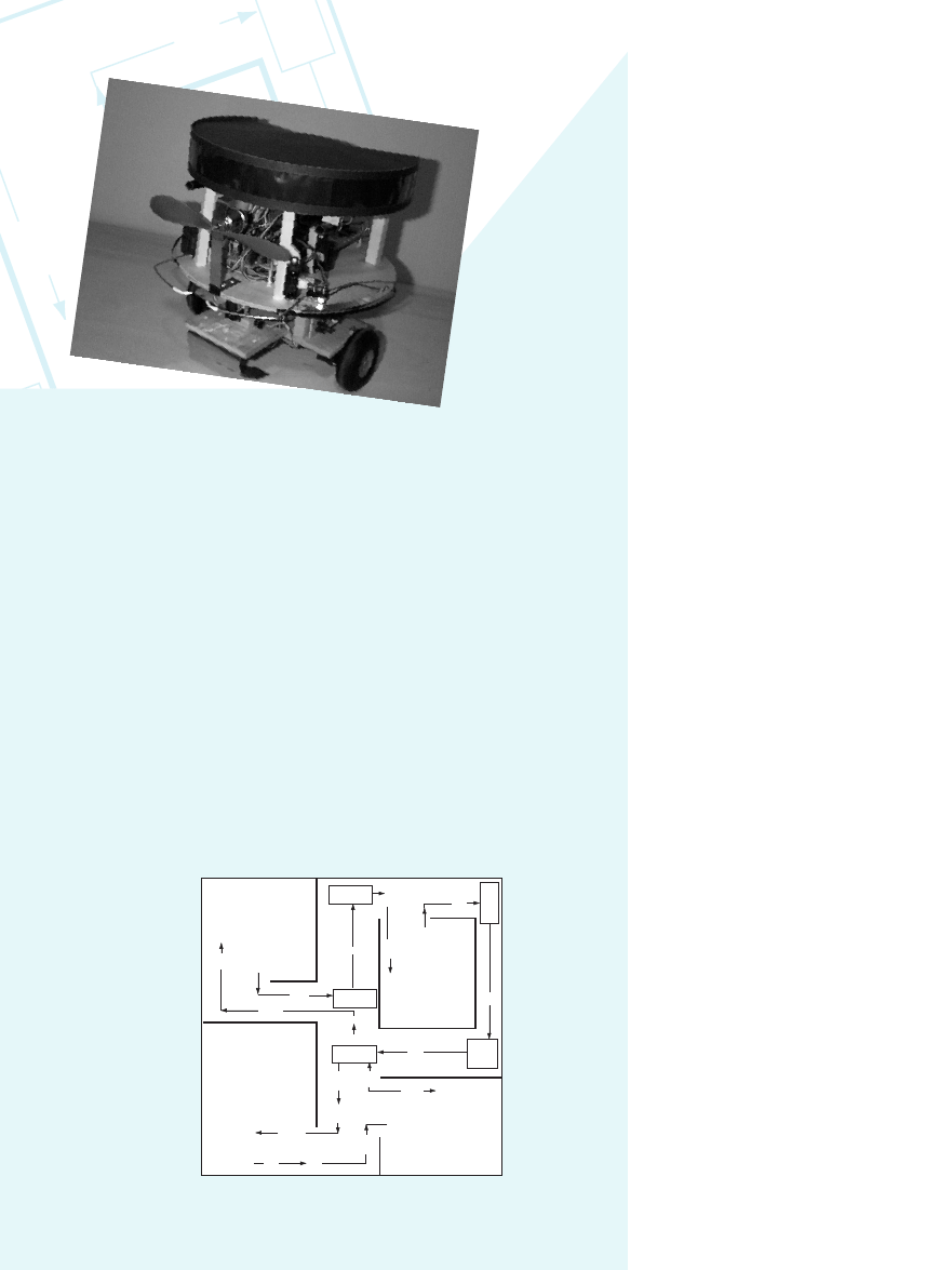
cuit. The designs often use neural
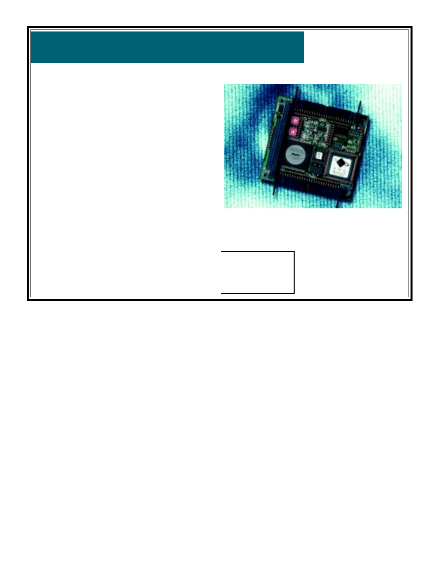
nets, as shown in Figure 1. The neural
net works like the heart of the robot
and always runs. By adding sensors,
the neural network can influence the
gait or operation. Examples of behav-
ior modifications include making it
walk slower, faster, backwards, and
change direction. Adding certain sen-
sors can increase the robot’s intelli-
gence and survivability.
BEAM circuits are inexpensive
because they require very few parts.
In contrast, a complex robot will be
able to do more operations, but will
cost more. For more detailed infor-
mation on such robots, read Living
Machines.
[4]
James M. Conrad
Mark van Dijk
A Simple Circuit for an Inexpensive Robot
Photo 1—
The Stiquito is an inexpensive hexapod robot
that uses nitinol for propulsion.
CIRCUIT CELLAR
®
Issue 120 July 2000
11
www.circuitcellar.com
DESIGN DESCRIPTION
Before designing the schematics of
the BEAMStiquito circuit, we listed
the requirements. First, we needed
inexpensive and easy-to-find parts. We
limited the number of parts because
of weight (Stiquito can carry about 50
grams) and size of the circuit board.
We used a maximum of two re-
chargeable AA batteries (2.5 V), be-
cause they are readily available and
weigh less than the robot (two batter-
ies weigh 40 grams). A rechargeable
9-V battery is expensive and probably
wouldn’t deliver enough current, so
we ruled out that possibility. Lastly,
the robot should be able to walk with-
out help.
We also had four design
wishes. We wanted to pro-
vide more power for the
nitinol wire to heat, there-
fore speeding up the robot.
Second, we wanted to pro-
vide a longer run-time of
the batteries and robot be-
fore recharging. Third, we
would use BEAM-like con-
trol to control each leg
separately. Fourth, we
would use as little energy
as possible.
We didn’t add difficult
controls like sensors and
other intelligence because
we felt that the design
should first prove that a
robot functions according to
the list of demands. After
that, it’s easier to expand
the robot’s capabilities.
SCHEMATICS
Each leg uses a separate
Nv neuron, so the Stiquito
needs a nervous network of
at least six neurons. This also means
it uses six inverters. Many BEAM
robots employ circuits with HCT
integrated circuits (ICs). We chose the
74HCT14 because it uses a Schmitt-
trigger, is low voltage, and contains
the six inverters. An RC (resistor-
capacitor) network separates each
inverter. There is a 1-s delay of the
RC network for switching because the
nitinol needs time to heat and cool.
This means R × C = 1. Because
minimizing the circuit’s power use is
required, values R1 = 10 M
Ω
and
C = 100 nF were chosen (see Figure 2).
Tests indicate that the circuit without
LEDs and transistors can supply a
maximum current of 12 mA per in-
verter (74HCT14). It would take 16
stacked inverters to deliver the cur-
rent for the nitinol legs. Such a design
would be silly! It’s better to use tran-
sistors to amplify the needed current.
In this circuit, approximately 6 cm
of 0.004
″
nitinol (~7
Ω
) is used per leg,
about 180-mA current is needed to
drive each leg. The ideal voltage sup-
ply is 1.3 V. Higher voltage would
also mean using more current, which
would increase speed and the risk of
damaging the nitinol wire. Because of
the high current draw, we didn’t build
a solar-powered BEAMStiquito.
The BD139 was chosen because of
the low voltage (2.5 V); high current
(180 mA); placement of the circuit’s
base, collector, and emitter; package;
and cost. To supply the transistor’s
base with the correct voltage, and
therefore be able to manipulate the
nitinol wire’s and transistor’s power,
a resistor (R2) was placed between the
inverter and resistor. R2 (470
Ω)
gives
about 1.8 V between the collector and
emitter, and R2 (1 k
Ω)
gives approxi-
mately 1.3 V. Using a lower R2 speeds
up heating the wire, but
also increases the risk of
damaging the nitinol
wire. So, the circuit has a
470-
Ω
R2.
We chose low-current
LEDs because of the mini-
mum power usage wish.
Yellow was used because
it was readily available.
PCB
A printed circuit board
(PCB) was made using the
schematics listed here.
The PCB artwork was
drawn by hand and opti-
mized to use as little
space as possible. A pro-
gram that allows lines
and circles to be drawn
on a grid of 2.54 mm was
used to create the PCB
that is shown in Figure 3.
The PCB contains two
holes for connecting the
power (V+). One hole is
needed for the battery’s
Figure 1—
By using one neuron for each leg, a six-
neuron core is created. Each neuron in this net only
influences one other neuron.
+V
+V
+V
Nitinol
Nitinol
Nitinol
ECB
ECB
ECB
+V
+V
+V
Nitinol
Nitinol
Nitinol
ECB
ECB
ECB
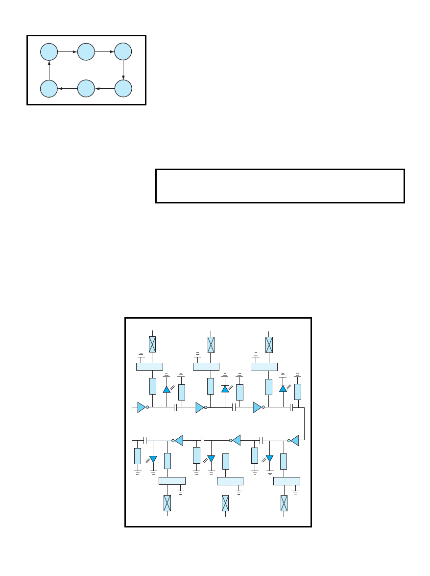
Figure 2—
The layout of the BEAMStiquito shows a 74HCT14, six RC net-
works, and six transistors. The LEDs are optional.
Current circuit drain
0.1 mA at 2.5 V
without LEDs and nitinol
Current circuit drain
50 mA at 2.5 V
without nitinol
Current circuit drain
500 mA at 2.5 V
without LEDs
Current drain of the complete circuit
550 mA at 2.5 V
Table 1
—This shows how much power the robot uses.
12
Issue 120 July 2000
CIRCUIT CELLAR
®
www.circuitcellar.com
V+ and the other hole is for attaching
the battery to the Stiquito’s power bus.
The transistor’s emitter can be
attached to the other side of each leg.
Connect the outputs of each of the
inverters to generate a tripod gait.
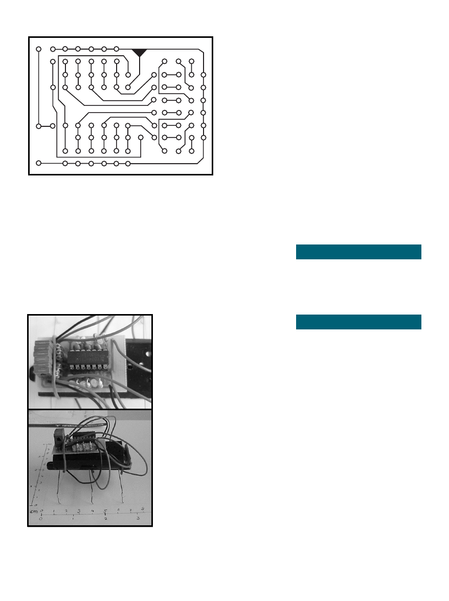
Photo 2a shows the completed board
that was used for the BEAMStiquito.
A WALKING BEAMStiquito
The BEAMStiquito robot contains
LEDs and transistors, so it’s easy to
see when the robot is still walking.
Mark van Dijk has a BS in mechani-
cal engineering. He lives in Enschede,
The Netherlands, where he is a de-
signer. You may reach him at
_muffed@yahoo.com.
James M. Conrad received a BS in
computer science from the University
of Illinois, Urbana, and his master
and doctorate degrees in computer
engineering from North Carolina
State University. He is an engineer at
Ericsson, Inc. and an adjunct profes-
sor at North Carolina State Univer-
sity. He is the author of numerous
book chapters, journal articles, and
conference papers about robotics,
parallel processing, artificial intelli-
gence, and engineering education.
You may reach him at jconrad@
stiquito.com.
SOFTWARE
The parts list for the BEAM-
Stiquito project is available on the
Circuit Cellar
web site, along with
MPEG footage of the hexapod in
action.
RESOURCES
[1] James M. Conrad and Jonathan
W. Mills, Stiquito: Advanced
Experiments with a Simple and
Inexpensive Robot
, IEEE Com-
puter Society Press, Los
Alamitos, CA, 1997.
[2] James M. Conrad and Jonathan
W. Mills, Stiquito for Beginners:
An Introduction to Robotics
,
IEEE Computer Society Press,
Los Alamitos, CA, 1999.
[3] James M. Conrad and Serge
Caron, “A Simple Circuit to
Make Stiquito Walk on its Own
Effectively”, Robot Science and
Technology Magazine
, 2000.
[4] Brosl Hasslacher and Mark W.
Tilden, “Living Machines”,
Robotics and Autonomous Sys-
tems: The Biology and Technol-
ogy of Intelligent Autonomous
Agents
, Elsivier Publishers,
1995.
[5] Paul Trachtman, “Redefining
Robots” Smithsonian, February
2000, pp. 96-112.
+
MVD
6–'99
–
When the lights stop, the batteries
need to be replaced.
The robot is 70 mm × 75 mm ×
50 mm and weighs 50 grams includ-
ing batteries (see Photo 2b). Its speed
is 3–5 mm per step. The robot can
step down from 4-mm high objects.
Currently, the robot we designed can
only walk forward. Table 1 provides a
list of some of the robot’s power usage
measurements.
Several MPEG movies that show
the BEAMStiquito in action can be
downloaded from Circuit Cellar’s web
site. The movies were recorded as 10
frames-per-second AVI movies and
converted to 24 frames-per-second
MPEG movies, so the robot walks 2.4
times faster in the movies than it
does in reality.
FUTURE PLANS
This circuit provides an excellent
way to learn about the Stiquito,
BEAM concepts, and robotics basics.
Although this robot works on many
levels, it can be improved.
Electrical and mechanical modifi-
cation give the legs a second degree of
movement. This can be done by con-
trolling each leg with two nitinol
wires instead of one. The robot also
lifts its leg while moving forwards or
backwards.
Another way to improve the robot
is to make it more aware of its sur-
roundings by adding sensors. Sensors
can send a signal so it will react to
certain environments or obstacles. For
example, the robot could avoid ob-
stacles in its path or stop in front of
an abyss.
I
Figure 3—
Here’s the PCB
artwork for the BEAM
Stiquito. The solder side is
shown. If you reproduce this
artwork, keep the 2.54-mm
spacing for the IC holes.
Photo 2—
The close-up photo of BEAMStiquito (a)
shows the compact layout and population of the board.
On the fully-functional BEAMStiquito (b), the battery is
between the circuit board and the Stiquito robot. Be
careful not to short the robot contacts.
a)
b)

14
Issue 120 July 2000
CIRCUIT CELLAR
®
www.circuitcellar.com
Tu
le
Turn
around
Doorw
ay
3
Tur
right
T
he
shiny treaded
invention on this
month’s cover is not
the latest lunar exploration
craft, it’s Marc Warren’s Max
dV, and it was just one of the
many robots that participated in the
2000 Fire Fighting Home Robot Contest
at Trinity College in Hartford, CT. This year
was the seventh annual contest at Trinity
College. With the help of some great sponsors,
contest administrator Jake Mendelssohn has gotten robotics
teams and enthusiasts from across the country and around the
world “fired up” about this competition. This year’s contest
was no exception. For those of you who may not be familiar
with the contest, let’s take a spin through the preliminaries.
The objective of the contest is to build a computer-
controlled robot that can move through a model floor plan
structure of a house (see Figure 1), find a lit candle, and then
extinguish it in the shortest time. The contest objective is meant
to simulate the real-world operation of a robot performing a
fire security function in an actual home or warehouse setting.
This is not a maze contest where the robot has to figure out
how to move through the structure. The design of the structure
is known beforehand. However, just like in the real world
where there is always a measure of uncertainty in any
information, the dimensions in the contest structure floor plan
are approximations. The actual dimensions may vary up to as
much as an inch from the given values.
The walls of the structure are made of
wood and are 13
″
high.
The walls are painted
flat white and the floor
of the arena is a
smooth wood surface
painted flat black. All of
the hallways and
doorways to rooms are
18
″
wide openings (no
doors). There is a white
1
″
wide line of white tape
or paint on the floor across
each doorway to indicate
the entrance to each room.
Each robot must start at the
home circle location that is
marked on the arena floor
plan, but it can go in any
direction desired from there.
Because this contest is
intended to simulate a real-
world experience in which a
robot could be used to extinguish a fire within a known
structure, there are some rules that prevent less-than-practical
methods of accomplishing this task. Robots are penalized for
each time they bump into the walls during the mission. No
trails of bread crumbs or any other marks may be made on
the floor to aid in navigation.
Although flooding the entire arena with CO2 would
extinguish the candle, the robot must have found the candle
before it attempts to put it out. And one of my favorite rules,
“The Robot must not use any destructive or dangerous methods
to put out the candle. For example, the Robot can not explode
a firecracker and put the candle out with the concussion.” (I
have to wonder whether this rule was included as an ounce of
prevention, or a pound of cure.)
The maximum size of each robot is 12.25
″
× 12.25
″
×
12.25
″
. Other than that, restrictions are kept to a minimum to
promote a
variety of approaches. There are no
restrictions on the robot’s weight or the
types of materials used to construct the
robot. The max electrical requirement for any
system needing electrical connection is 20
A at 120 VAC.
To achieve the contest objective of
building a robot that can find and
extinguish a fire in a house, finding the
fire within a reasonable period of time
is important. The maximum time limit for
a robot to find the candle is six minutes
and the maximum time for the robot to
return to the Home circle in the Return
Trip mode is three minutes. To make
the contest realistic and to
encourage the creation of smart
robots, the candle is randomly
moved to different rooms for each
trial so the robot truly has to
search to find the candle.
Of course, there are prizes for
the robots that finish with the
lowest final scores, but for many of
the contest entrants, it’s not about
18"
18"
18"
18"
18"
18"
18"
18"
H
34.5"
17"
31''
25"
31''
51"
9.5"
41.5"
23"
45.5"
45.5"
2000 Trinity College
Fire Fighting Home
Robot Contest
Edited by Rob Walker
Figure 1This is
home sweet home for
firefighting robots.
BEATING

CIRCUIT CELLAR
®
Issue 120 July 2000
15
www.circuitcellar.com
m
3
Turn
eft
Intersection
4
Doorw
ay
4
Turn
right
Turn
around
T
Turn
right
Intersection
2
rn
ht
Turn
left
Intersection
3
Turn r
ight
Turn
left
Room
4
the robot a 360
°
field of view. When
the robot enters a room with a candle,
digital signals derived from this first
level of sensors locate the fire within a
90
°
arc. The robot then turns towards
the flame and engages the second
level of detection (a Hamamatsu
UVtron IR Sensor) to confirm the first
detection. If there is a confirmation,
the third level detection system
engages (two additional Honeywell IR
sensors). These sensors use the two
analog signals to act as a binocular
system to home in on the candle
flame, while remaining insensitive to reflections. When it finds
the flame the robot carefully approaches the candle and
extinguishes it using a fan mounted on top of our robot.
After three weeks of modifying our MRK1 kit, we were able
to take on the “best” at the competition. We overcame the
common problem of the sodium vapor lighting interfering with
the fire detecting sensors by isolating the sensors to protect them
from any stray IR sources other than the flame we were seeking.
The day of competition finally arrived and our nerves of
steel had turned to nerves of putty as we awaited our runs.
Thankfully we had the foresight to build and enter two
identical robots. After frantically swapping subsystems, we
discovered that one of our robots had a power drain
somewhere on it, so we had to rely on our second robot to
pull through. We put MRK1+ to the test by using a ramp in
the maze on our second run, which yields bonus points. Our
robot successfully maneuvered over the ramp, and we were
given the bonus points. This gave us the guts to do our third
and final run with the ramp, which boosted our score enough
to receive second place. The two MRK1+ twins, as we like to
call them, had saved the day.
'
Julie Wiens
New Mexico Tech
Socorro, NM
ALL TERRAIN ROSIE
Power: 8 “AA” cell batteries
Locomotion: 6 DC motors
Brains: Siemens 80C517 microcontroller
the prizes. There’s the satisfaction of
improving on last year’s design,
beating a rival university’s time, or
even just watching the excitement
among the next generation of
inventors and engineers in the Junior
division. In 1999 a walking Robot
was entered in the contest. The device
walked on two legs, and found and
extinguished the candle. The robot
was far too slow to win the contest, but it
inspired the “Spirit of the Inventor” award for the most unique
robot that does not win the contest, but shows the greatest
creativity and ingenuity. Marc Warren’s Max dV was the
recipient of the award at this year’s contest.
For the official rules and details, visit www.trinicoll.edu/
~robot. Now, let’s take a look at just what goes into entering
the firefighting robot contest.
'
NEW MEXICO TECH
This past year, at New Mexico Tech, a group of students
and professors designed a simple autonomous robot called
MRK1 (Mobile Robot Kits are available at www.ee.nmt.edu/
~mrobokit). We designed this robot to help teach high school
and college students about robotics. We decided to modify
the MRK1 and enter it in the Fire Fighting Competition. We
saw this as a great opportunity to show that the simple kit we
offer can be used in many ways. By adding additional
subsystems (sensors, fire-suppression, etc.) and developing
code, MRK1 became MRK1+.
MRK1+ uses five infrared (IR) proximity sensors (Sharp
GP2D12’s) to navigate the maze: a single front proximity
sensor to avoid frontal collisions, and two proximity sensors
on each side of the robot to control both the position and
orientation of the robot relative to the wall it is following. The
“brain” of MRK1+ is a Motorola HC12 Microprocessor. With
a simple differential drive system and two caster wheels for
support, the MRK1+ is ready for navigation.
To detect and extinguish a fire, we created a redundant
fire detection system with three levels of detection. The first
level consists of a ring of eight Honeywell IR Sensors giving
Photo 1A pair of firefighting detectives, the Twins
from New Mexico Tech competed at this years contest.
THE

16
Issue 120 July 2000
CIRCUIT CELLAR
®
www.circuitcellar.com
Tu
le
Turn
around
Doorw
ay
3
Tur
right
Navigating a
known floor plan is
accomplished by using
optical proximity detectors
to avoid the walls and turning
at specified distances from the
far (wall in front of the robot)
wall. For example, let’s say that
ATR is moving down a corridor
and the right proximity detector
senses a wall. The controller
stops all motors on the left side
of the robot until the right detec-
tor no longer senses a wall.
The sonar unit in the robot is
used for measuring the distance
to the end of a corridor. After
the robot makes a turn a value
is retrieved from a lookup table
that represents the distance between the far wall and where
the robot wants to turn. The robot is constantly measuring the
distance to the far wall and when the value from the lookup
table matches the value from the sonar the robot turns. Once
again the robot goes to a lookup table to determine the direc-
tion of the turn.
The exception to this method is when ATR enters a room
and detects a candle. At this time the robot aligns it’s wheel
base with the direction that the optical turret was facing when
the candle was detected and moves toward the candle. After
the candle is extinguished the robot uses the sonar to scan the
room and determines it’s location. After that it proceeds using
it’s initial method of navigation.
The speed is in controlled by pulsing voltage to the motors.
The longer the on time of the pulse the greater the speed. The
voltage generated by the motor during the off time of the
pulse is measured by the processor and is a indicator of how
fast the motor is turning. The processor then uses this informa-
tion to adjust the pulse on time for a constant motor speed
(standard PWM with back EMF speed control scheme).
The robot looks for the candle by sensing heat from the
flame. A first surface mirror mounted at 45° reflects the
candle light 90° down through an infrared fresnel lens that
focuses only (close to only) infrared energy into a point 2.2
″
below the lens. At the focal point there is an EG&G thermo-
pile which changes heat to a very small voltage. This voltage
is amplified and send to the control board for processing.
The microcontroller on the main control board uses a digi-
tal pot to adjust the gain of the signal to between 3.5 and 4
V. The entire time that the robot is not in a room, the proces-
sor is also adjusting a D/A converter which is used to trip a
comparitor fed by the thermopile. Upon entering a room, the
trip voltage is reduced by 1 V and the room is scanned for a
candle. When the mirror is facing toward a
candle, the voltage jumps to the rail (5 V)
and the comparitor trips, which triggers an
interrupt that records the direction the mirror
is facing.
Extinguishing the candle is accomplished
by releasing C02 stored in a small commer-
cially available cartridge. The cartridge is held in a device
sold to pump up bicycle tires and actuated by a DC motor
attached to the handle that wraps up dental floss around it’s
shaft (sounds stupid but it works great). When the robot
crosses the candle circle, the motor is turned on releasing
CO2 into the area.
'
Douglas Oda
KENSROBOT 2000
1999 was my first year attending the Fire Fighting Contest.
I was thrilled when my robot placed eighth in the senior
division. The robot used two Parallax Basic Stamp II
computers networked together for control. It’s sensors included
two homebrew IR range sensors, two line sensors, two
Hamamatsu UVtron flame sensors, a Precision Navigation
Vector 2X digital compass, two bumper sensors, and a sound
sensor. It used two Hitec RCD RC servos converted for
continuous rotation to drive the wheels and a RC servo to turn
the sensor head. A fan was used to extinguish the flame. The
robot ran in the non-dead-reckoning mode and successfully
returned to the starting circle most of the time.
My KensRobot 2000 was similar to the previous year’s
robot. It placed 13
th
at the 2000 contest with a score that was
eight times better than the previous year’s robot. There was
more competition at the 2000 contest with a lot of outstanding
robots participating.
KensRobot 2000 used one Basic Stamp II and two Basic
Stamp SX computers. All three computers were networked
together and one of the SX computers was connected to three
homebrew IR range sensors and two bumpers. This computer
accepted commands such as “Follow_Right_Wall” or
Photo 2Douglas Oda had All-Terrain Rosie up and rolling at
Trinity College.

18
Issue 120 July 2000
CIRCUIT CELLAR
®
www.circuitcellar.com
Room
3
Intersection
3
Tur
n right
Tur
n
left
“Forward_to_Wall.”
The Basic
Stamp II did the
signal conditioning for
the Hamamatsu UVtron
room flame detector. It also
measured the frequency of the
sound sensor circuit to determine
when to start (for participating in
the Sound Activation operating mode
category) and it operated the Vector 2X
digital compass. This computer
accepted commands like “Turn_North”
or “Turn_South_West”.
The second SX computer was the
master, sending commands to the other
two computers and monitoring the
homebrew candlelight detector, two
Sharp GP2D05 IR detectors (used to
detect the candleholder), and a floor
line sensor circuit. The master computer
also controlled the fan.
All three computers controlled the
two Hitec converted drive servos using a
Scott Edwards Electronics Mini SSC II
serial servo controller. This robot also
ran in the non-dead-reckoning mode
and was able to return to the starting
circle all of the time.
The Trinity College Fire Fighting
Contest provides an opportunity to talk
about robotics with people from around
the world, attend great seminars, and
actually meet some of the legends of the
amateur robotics community. Hope to
see you there next year.
'
Ken Boone
NOMAD
Nomad was constructed from the
remains of a much simpler robot that I
built a few years ago. The original
robot was run by a Basic Stamp II and
had just two infrared proximity sensors
and bumper switches. For Nomad, I
stripped all that off and reused the
gearboxes, motor control circuit, main
base, and wheels.
The main base is made of wood and
contains the gearbox/wheels, front
GP2D02 range sensor, batteries, and
motor control circuit. Above that there
are two circular platforms made of
plywood. Mounted to the lower platform
are the microcontroller, fan assembly,
bumpers, the other two GP2D02s, and
both GP2D15’s. The IR and CDS flame
sensors are mounted to the upper
platform.
The choice of microcontroller was
mostly based on past experience, but it
did provide a number of benefits. The
V25 Flashlight runs a form of DOS over
a serial port and has lots of memory—
512 KB of flash memory and 512 KB of
RAM. This enabled me to store several
programs on the flash disk for different
purposes.
For example, I have a sensor/
actuator test program, a flame detection
test program, and the main contest
software all stored on the flash disk.
Also, the V25 processor is an 8086
compatible processor, which permits
development using the Borland C++
development environment.
The flame sensors are interesting in
that they consist of seven infrared
phototransistor sensors arranged in a
240° semicircle. This approach
eliminates the need for scanning with a
single sensor, however, it complicates
calibration of the sensor readings
because the sensors respond to
reflections of light from the white walls,
and the closer the sensor is to a wall,
the greater the response. I solved this
Photo 3After Kens first entry in 1999, KensRobot
2000 was ready for the challenge.
CIRCUIT CELLAR
®
Issue 120 July 2000
19
www.circuitcellar.com
Interse
4
Stop
Doorw
ay
4
Tur
n
right
Tur
n
around
Tur
n
right
n
t
Room
4
problem by developing a self-calibration
procedure that operates when no
candle is present. During calibration,
Nomad enters each room and collects
readings from each sensor at the
ambient light level. From this
information it can calculate the
appropriate thresholds for candle
detection.
NAVIGATION SOFTWARE
The contest rules recognize two
navigation methods—dead-reckoning
and non-dead-reckoning. Dead
reckoning computes the robot’s current
position by measuring the distance and
heading of travel from a previously
known position. Non-dead-reckoning
computes the robot’s position from
observations of its environment (like
walls, doorways, etc).
Pure dead reckoning navigation is
not very useful in the real world, as
errors accumulate
over time and
eventually cause
the robot to get
lost. Consequently,
a 40% reduction
in score (lower is
better) is given to
robots that use
non-dead
reckoning. I
wanted to take
advantage of this
factor, so I
decided to
develop a non-
dead-reckoning
navigation system.
The first task
in developing the
system was to
analyze the types of
motion that would
be required for
success. Nomad
would need to
navigate to each
room in some
sequence. This meant it had to travel
down one or more hallways, enter a
room, and stop and check for the flame.
If no flame was detected, it had to turn
around, exit the room, and move on to
the next room. These actions implied a
wall-following behavior in the hallways,
90° turns at certain points, and 180°
rotations inside of rooms.
Wall following between nodes is
accomplished using two techniques. The
first is to take successive readings using
the side IR ranging sensors, and
determine if the robot is moving closer,
or further away, from the wall. Slight
course corrections are applied if the
robot is too close to a wall and moving
closer, or too far away and moving
further. The other technique uses the two
IR proximity sensors. These sensors are
mounted at about 35 degrees off the
robot centerline (one on each side). This
angle allows
Nomad to
look ahead
of it and
sense if it is
drifting
towards an
approaching
wall. If so, a
course
correction is
applied until
the condition
clears.
Once
Nomad
could travel
safely down
Photo 4Nomad was
set to wander the
halls and find the
fire this year.
Room
3
Turn
left
Turn
around
Intersection
4
Intersection
1
Home
Turn
left
Stop
Doorway
4
Turn
right
Turn
around
Turn left
Turn
right
Turn
left
Turn
around
Tu
rn
around
Turn
right
Doorw
a
y
2
Doorw
a
y
1
No
action
Tu
rn
right
Intersection
2
Doorway
3
Turn
right
Turn
left
Intersection
3
Turn right
Turn
left
Room
2
Turn
right
Room
1
No
action
Room
4
Figure 2This navigation map keeps Nomad on track.

20
Issue 120 July 2000
CIRCUIT CELLAR
®
www.circuitcellar.com
Tu
le
Turn
around
Doorw
ay
3
Tur
right
a hallway, the next
problem is knowing when and
where to turn. The software
divides the arena into nodes that
represent turning points (see Nomad
map). For example, the home position is a
node, and the intersection down the first hallway
is a node. Doorways, corners, and rooms are also
nodes. Since all turns are at right angles, there are
only four directions Nomad could be moving while
searching for the candle. I call these directions
north, south, east, and west (although Nomad has
no real compass sense). From the home position, north is
always pointed down the first hallway (see Figure 2).
Each node contains a variety of information. The Wall-to-
Follow information indicates which wall should be followed
given the current direction. Exit Paths keeps a pointer to a
node if there is a physical path from one node to another
node in a certain direction. Exit Criteria specifies the
conditions that must hold for the robot to move from one node
to another in a certain direction. And last, Entry Actions
contain the actions to execute when entering a node from a
certain direction.
Consider the values for the home node moving north:
Home Node
Direction: North
Wall-to-Follow
Left
Exit Path
Intersection 1
Exit Criteria
Front range < 15
″
AND left range > 9.5
″
These values tell Nomad to follow the left wall and monitor
the front and left infrared ranging sensors to determine when
to enter the node Intersection1. The exit criteria are specified
so that Nomad looks for an approaching wall (front range <
15 inches), and a clear left hallway (left range > 9.5 inches).
When both of these conditions are true, the node
Intersection1 is entered.
The final piece to the navigation puzzle is the entry action.
Entry actions are what make Nomad turn left, right, stop, and
such. They are only executed when a node is entered. So in
the example above, when Intersection1 is entered, the entry
action associated with the current direction (north) would be
executed. The action would be to turn left, and the current
direction would then change to west.
Actions such as turning left or right could use dead
reckoning too, but I decided to implement turns based on
sensor readings. For example, when turning left at
Intersection1, Nomad monitors the front sensor range and
completes the turn when the range exceeds some threshold.
The act of turning
completely around after checking a room is
also sensed in a similar manner. Implementing the actions
this way allows Nomad to continuously correct its course
travel.
Although this approach is more complicated than dead
reckoning, it has the advantage of not requiring precise
motion or highly accurate encoder measurements. Sloppy
gearboxes, wheel slippage, floor bumps, or inaccuracies in
maze construction do not affect the algorithm. It even hid a
bug in my motor control software. At one point in
development, the left motor was being controlled properly, but
the right motor was not, resulting is significantly less power on
the right side. Nomad was still able to navigate the maze
properly despite a strong desire to veer to the right!
'
Jim Cannaliato
ROBOT X
This was our first year to compete at the Trinity contest, but
not our first time to compete with this robot. We started
working on the robot in the spring of ‘98 for an
undergraduate project laboratory. Our region of the IEEE
(region 5) sponsors a robotics contest every year, and for the
last two years it was based on the Trinity rules. We competed
in spring ‘98 and spring ‘99, giving us some prior experience
coming into the contest.
We named the robot X. We chose to use a two-wheeled/
drag caster layout, using a fan for the extinguisher. It has a
68HC12 microcontroller on the Motorola evaluation board.
Debugging and calibration information is sent to a two line
LCD. A/D lines are used for the four wall sensors, the floor
sensor, and the candle sensor. A single button is used for
operator input. Optoisolators were used to completely
separate the motor power supply from the controller supply.
The motors are powered from two 7.2V radio control car
batteries, with another 7.2 to power the controller.
The wall sensors are fairly simple: IR LEDs and
phototransistors from Radio Shack, for front, back, right, left,
Photo 5The team from Texas Tech brought RobotX to battle the
blaze and face the challenge.

CIRCUIT CELLAR
®
Issue 120 July 2000
21
www.circuitcellar.com
m
3
Turn
eft
Intersection
4
Doorw
ay
4
Turn
right
Turn
around
T
Turn
right
Intersection
2
rn
ht
Turn
left
Intersection
3
Turn r
ight
Turn
left
Room
4
and the floor (white line sensor). Originally, we were just
reading the intensity of the reflection directly off the
phototransistors into the A/D converter on the HC12. This
worked fine in the lab, but uneven ambient light from sources in
other environments wreaked havoc on the intensity readings. To
eliminate the interference from the ambient lighting, we had to
modulate. We chose 1 kHz as a compromise between the 120
Hz from the overhead lights and 40 kHz, which we knew is
commonly used for other infrared application (remote controls,
video camera rangefinders, etc.).
Our candle sensor uses the same Radio Shack
phototransistor as the wall sensors. In our first tests, we had
trouble picking up the candle all the way across the two big
rooms. After some experimentation, we found that adding a
parabolic reflector cut down from a flashlight improved the
sensor performance. The parabolic reflector provides
amplified readings and improved directionality.
We chose stepper motors to drive the robot, to get better
precision. We mounted the wheels directly to the shafts of the
motors rather than gearing the motors down. With sensors
and two stepper drivers in place, moving along a wall was
not difficult. As we tried to push the speed higher, the motors
began to miss steps. To increase the torque and decrease the
slipping, we applied twice the current than the motors were
rated for. This made the motors get fairly hot during a run, but
we decided that this was worth the increased speed.
X placed 7th at the contest, which we were proud of for
our first time there. We would like to thank the Electrical
Engineering department at Texas Tech for funding us and
sending us to Trinity.
One of the most interesting and entertaining aspects of this
project has been the development of the code. The majority of
our development time was spent on programming, not on the
hardware. We wrote the code entirely in assembly language.
This allowed for easier manipulation of inputs and outputs, but
it brought with it many headaches.
Writing in assembly language complicates many
programming tasks, such as loops and variable tracking.
Testing the software with every single test case was really
impossible, so many times a small change made one day
would cause problems days later when we changed
something else (like putting
the candle in a different spot).
We were often nervously trying to
solve these problems a few minutes
before a competition (also during
competition between runs!)
The first year that we worked on the robot, we
had some interesting problems with the code space
available the Motorola 68HC12B32. This chip has 1 KB of
RAM, 768 bytes of byte-erasable EEPROM, and 32 KB of
flash EEPROM. We originally started writing code in the byte-
erasable, because it can be written on the order of 100,000
times.
The flash memory was only rated for around 100 cycles.
After we filled up these 768 bytes, we decided to move on to
the flash. This worked for a while, until we accidentally
destroyed the flash erase circuitry (The manual said to apply
a 12-V programming voltage; the manual addendum said not
to go over 11.8 V. Oops.).
At this point, rather than buying a new board, we went
back to the byte-erasable (all 768 bytes of it.) This is
obviously not a lot of space for fire-fighting robot code, but
we were determined to make it work. Hours upon hours were
spent shortening the code to make it fit. A running tally was
kept of the code space left, and whenever any member of the
team had any free time, he was down in the lab trying to
squeeze a couple more bytes out of it. The code was virtually
unreadable to anyone not actively involved in this process,
but it worked. The entire code was squeezed into 765 of the
available 768 bytes the day before our first competition.
Later that night, we decided to write code for returning to
the starting circle after the candle was put out. As we were
out of byte-erasable space, we put this code in RAM.
Unfortunately, this required a reload every time the power
was turned off. This was obviously not very practical, but it
worked.
After that year we bought a new evaluation board, which
made dealing with code much easier. We had to rewrite most
of the software, because it was virtually impossible to deal
with our original squeezed-down code. 32K of code space is
much more comfortable than 768 bytes. The additional
memory allowed us to build modular robot functions without
major concern for size. After developing core modules for
basic robot activities (such as moving motors, reading
sensors, controlling LCD), we were able to modify the robot’s
behavior quite easily.
'
John Walter, Brent Short, Jason Plumb, Stephen Frisbie
Texas Tech University Electrical Engineering
Will we see you
there next year?

22
Issue 120 July 2000
CIRCUIT CELLAR
®
www.circuitcellar.com
USB Chip Choices
FEATURE
ARTICLE
i
Today, most periph-
eral devices are de-
signed with USB
connections. Design-
ing USB peripherals
can get tricky, but
choosing the right
chip can make a
world of difference.
Jan knows her USB,
so you might want to
choose to listen up.
f you’re design-
ing a device that
will connect to a PC
or Mac, you’ll probably
use a universal serial bus (USB). You
may have noticed that the ports that
served PCs for 20 years are disappear-
ing. USB was designed from the
ground up to replace a variety of
legacy ports with a single interface
that’s flexible and easy to use.
But simplicity for end users has a
price
the interface is more compli-
cated than the single-purpose ports it
replaces. To manage the complexity,
every USB peripheral must contain an
intelligent controller that knows how
to respond to the requests defined by
the specification. The good news for
developers is that there are plenty of
choices for controllers.
This article will help you find the
USB controller that gives the best
performance. I’ll start with a quick
tour of USB and a review of the re-
sponsibilities of USB peripherals.
Then, I’ll discuss how to narrow the
choices. I won’t describe every chip,
but I will present advantages and
disadvantages of some popular chips.
USB, IN BRIEF
USB is suitable for nearly any ap-
plication that needs a slow to moder-
ate-speed connection to a host CPU
with USB support. This article will
concentrate on Windows 98 and 2000
hosts, but a host can be any computer
with host-controller hardware and
operating system support. USB periph-
erals include standard devices like
keyboards, mice, and printers, as well
as test instruments, control systems,
and other small-volume or custom
designs. Video and other high-speed
applications will most likely use
IEEE-1394/Firewire.
One goal of USB is freeing users
from technical and logistical hassles.
There’s no need to assign IRQs or port
addresses. Inexpensive hubs make it
easy to add peripherals without hav-
ing to open the box and find a slot.
There’s only one interface. And the
interface can provide up to 500 mA at
a nominal 5 V, so many peripherals no
longer need a wall wart or AC power
cord for an internal supply.
The host controls the bus and
keeps track of which devices are at-
tached. It also ensures each data trans-
fer gets a fair share of the time. Inside
the peripheral, the controller hard-
ware and embedded code respond to
transmissions from the host.
USB is the product of a consortium
that includes Intel, Microsoft, and
other companies. The organization,
the USB Implementers Forum, spon-
sors a web site (www.usb.org) that has
the specification documents and tools
for both developers and end users.
HOST COMMUNICATIONS
Even if you’re designing only the
peripheral side, it’s helpful to know
how the host communicates. Win-
dows uses a layered driver model for
USB communications. Each driver
layer handles a portion of the commu-
nication (see Figure 1).
Applications communicate with
device drivers (including class drivers)
that communicate with the system’s
bus drivers, which access the USB
hardware. Windows includes bus
drivers and some class drivers.
For Windows, a device driver for a
USB device must conform to Win32
Driver Model (WDM). A WDM driver,
supported by Windows 98 and 2000, is
an NT kernel-mode driver with power
management and plug-and-play.
Jan Axelson
Finding a Peripheral Controller

CIRCUIT CELLAR
®
Issue 120 July 2000
23
www.circuitcellar.com
A device may have its own driver,
or use a generic class driver that
handles communications with any
hardware that conforms to a class
specification. Windows adds class
drivers with each release (see Table 1).
If your device isn’t in a supported
class, you must provide a driver.
How does Windows decide which
driver to use with a device? Every
device stores a series of data struc-
tures called descriptors. Every Win-
dows system has a variety of INF
files, which are text files that match
drivers with class codes or vendor and
product IDs stored in the descriptors.
When the files detect an attached
device, the host performs an enumera-
tion process that requests the descrip-
tors. All devices must know how to
respond to the enumeration requests.
The host compares the information in
the descriptors with the information
stored in the system’s INF files and
selects the best match. Some products
provide their own INF files, others
use files provided with Windows.
TRANSFERS
USB 1.1 supports two speeds. Full
speed is 12 Mbps. Low speed, which is
intended for inexpensive devices and
devices that need flexible cables, is
1.5 Mbps. The latest release, version
2.0, supports 480 Mbps, but requires
new hardware in the host, peripheral,
and any hubs between.
A single peripheral’s data transfer
rate is less than the bus rate and not
always predictable. The bus must also
carry addressing, status, control, and
error-checking information. Any pe-
ripheral may have to share bus time
with other peripherals, although a
device can request guaranteed delivery
rate or maximum latency between
transactions. Low-speed transfers are
limited to a fraction of the bus time
so that they don’t clog the bus.
To make the bus practical for de-
vices with different needs, the specifi-
cation defines four transfer types:
control, interrupt, bulk, and isochro-
nous (see Table 2).
Control transfers are the only
transfers that every device must sup-
port. Enumeration uses control trans-
fers. With each, the host sends a
request. The specification defines
requests that devices must respond to,
and a class or individual device driver
may define extra requests.
Along with each control request,
the host sends a 2-byte value and a 2-
byte index, which the request can
define in any way. Depending on the
request, either the host or device may
send data. The receiver returns an
acknowledgement. However, there is
no data stage with some requests, and
the device returns an acknowledge-
ment after receiving the request.
The other transfers don’t use de-
fined requests. They transfer blocks of
data and identify and error-check
information to or from a device.
Interrupt transfers are useful for
applications that need to send small
amounts of data at intervals, such as
keyboards, pointing devices, and other
monitoring and control circuits. A
transfer can send blocks of up to 64
bytes with a guaranteed latency
(maximum time between transac-
tions) of 1 to 255 ms.
Bulk transfers are useful for appli-
cations that need to transfer large
amounts of data when delivery time
isn’t critical, such as printing and
scanning. A bulk transfer can send
blocks up to 64 KB, but without guar-
anteed delivery time.
Isochronous transfers are used
when delivery rate is critical and
errors can be tolerated, such as audio
to be played in real time. An isochro-
nous transfer can send up to 1023 Bpms
with a guaranteed attempt to send a
block of data every millisecond. Un-
like the other transfers, isochronous
transfers have no handshake packet
that enables the receiver to notify the
sender of errors detected within data
that is received.
USB transfers consist of one or
more transactions. Each transaction,
in turn, contains identifying informa-
tion, data, and error-checking bits.
Inside the device, all USB data
travels to or from an endpoint, which
is a buffer that stores data to be sent
or received. A single device can have
up to 16 endpoint numbers (0–15). An
endpoint address is the endpoint num-
ber plus its direction: in (device-to-
host) or out (host-to-device). Every
device must support endpoint 0 in and
out for control transfers and may
support up to 30 additional endpoints.
Most controllers support fewer
than the maximum number of end-
points and some don’t support all of
the transfer types. Low-speed control-
lers are limited to using control and
interrupt transfers. Cypress Semi-
conductor’s EZ-USB is one chip that
supports the maximum number of
endpoints (one bidirectional control
endpoint plus 30 additional endpoints)
and all four transfer types.
The host controls the bus and ini-
tiates transfers. But, a device in the
low-power suspend state can use the
remote wake-up feature to request a
transfer. And a device can request the
host to send or request periodic inter-
rupt or isochronous data.
ELEMENTS OF A USB CONTROLLER
A USB peripheral controller has
several responsibilities. It must pro-
vide a physical interface to the bus
and detect and respond to requests
and other events at the USB port. And
it provides a way for an internal or
external CPU to store data that it
wants to send and retrieve.
Controller chips vary by how much
firmware support they require for
these operations. Some, such as
NetChip’s NET2888, require little
more than accessing a series of regis-
ters to configure the chip and store
and retrieve bus data. Others, such as
Cypress’ M8 series, require routines
to manage data transfers and ensure
that the appropriate handshaking
information is exchanged.
Applications
Win32 API calls
Win32 sub-system
Hardware device drivers
Bus drivers
Hardware
Hardware-specific interface
I/O request packets
I/O request packets
User
mode
Kernel
mode
Figure 1—
USB communications use a layered driver
model in Windows 98 and 2000. Each layer handles a
portion of the communications. Bus drivers and some
class/device drivers are provided with Windows.

24
Issue 120 July 2000
CIRCUIT CELLAR
®
www.circuitcellar.com
documented, bug-free sample firm-
ware for an application similar to
your project. And fifth, it can commu-
nicate using device drivers included
with Windows or another well-docu-
mented driver that you can use with
minimal modification.
These are not trivial consider-
ations. The correct choice will save
many hours and much aggravation.
ARCHITECTURE CHOICES
Some USB controllers contain a
general-purpose CPU, and others have
a serial or parallel interface that must
connect to an external CPU.
A chip with a general-purpose CPU
may be based on an existing family
such as the 8051, or may be designed
specifically for USB applications.
Controllers that interface with an
external CPU provide a way to add
USB to any microcontroller with a
data bus. The external CPU manages
non-USB tasks and communicates
with the USB controller as needed.
For applications that require fast
performance, another option is to
design an application-specific inte-
grated circuit (ASIC). Components are
available as synthesizing VHDL and
Verilog source code.
Cypress has several chips that
contain a CPU developed specifically
for USB applications. The M8 family
includes the CY7C6xxx series of inex-
pensive chips, each with two to four
endpoints, 12 to 32 general-purpose I/
O lines, and 2 to 8 KB of program
memory. Note that the program
memory is one-time programmable
(OTP) EPROM.
The instruction set is short (35
instructions), so learning it isn’t diffi-
cult. However, this also means you
won’t find detailed instructions that
do most of the work for you. For ex-
ample, there are no instructions for
multiplying or dividing; calculations
must be done by adding, subtracting,
and bit shifting (Cypress offers a C
compiler from Byte Craft with exten-
sive math functions).
For 8051 users, Cypress’ EZ-USB
has an architecture similar to Dallas
Semiconductor’s 80C320. Two other
early 8051 compatibles were Intel’s
8x930 and 8x931. Intel stopped manu-
facturing both of these this year but
licensed the technology to Cypress.
If you have 8051 experience, espe-
cially if you’re designing a USB-ca-
pable version of an existing 8051
product, sticking with the 8051
makes sense. Even if you’re not famil-
iar with the architecture, its popular-
ity means that programming and
debugging tools are available, and
you’re likely to find sample code and
advice from other users on the
Internet. Keil has C compilers for the
8x930/1, and both Keil and Tasking
have a C compiler for the EZ-USB.
Other examples of families with
USB-capable chips are Mitsubishi’s
740, 7600, and M16C, Motorola’s
HC05, and Microchip’s PIC16C7x5.
Controllers that interface to exter-
nal CPUs typically use a parallel or
synchronous serial interface. An inter-
rupt pin signals the CPU when the
controller receives USB data or is
ready for new data to send. This
works if you want to use a CPU that
doesn’t have a USB-capable variant.
Philips’ PDIUSBD11 has an I
2
C
interface that uses three pins, a clock
input, bidirectional data, and an inter-
Some chips use registers, and oth-
ers reserve a portion of data memory
for transmit and receive buffers.
For faster transfers, Philips
Semiconductor’s PDIUSBD12 has
double buffers that store two full sets
of data in each direction. While one
block of data is transmitting, the
firmware can write the next block of
data into the other buffer so it’s ready
when the first block finishes trans-
mitting. In the receive direction, the
extra buffer enables a new tran-
saction’s data to arrive before the
firmware finishes processing data
received in the previous transaction.
In both cases, the hardware automati-
cally switches between the buffers.
A controller likely will have an
interface other than the USB port to
the outside world. In addition to gen-
eral-purpose I/O pins, a chip may
support other serial interfaces, such as
an asynchronous interface for RS-232
or synchronous interfaces, such as I
2
C
or Microwire.
Some chips include special inter-
faces. For example, Philips’ USA1321
contains a digital-to-analog converter
(DAC) for USB speakers and other
audio devices. NetChip’s NET1031 is
a scanner controller with a USB inter-
face. Dallas Semiconductor’s DS2490
is a USB-to-1–wire bridge.
SIMPLIFYING THE PROCESS
Aside from the chip’s features, easy
development affects how long it takes
to get a project running. The simplest
and quickest USB project meets the
following criteria. First, you must be
familiar with the project’s chip archi-
tecture and programming language.
Second, the project has a development
system that enables easy firmware
downloading and debugging. Third, it
has detailed, well-organized hardware
documentation. Fourth, there is well-
Table 1—
Each release of Windows added drivers for new classes of USB devices. If your device fits into one of the
supported classes, you don’t need to write a driver for it.
Windows edition
USB device drivers added
Windows 98 Gold (original)
audio HID 1.0 (includes keyboard and pointing devices)
Windows 98 SE (second edition)
HID 1.1 communications (modem) still image capture
(scanner, camera), (first phase/preliminary)
Windows 2000
mass storage printer
Windows 98 Millennium
Table 2—
The USB’s four transfer types are designed to meet different application needs.
Low
Guaranteed
Guaranteed
Transfer
speed
Error
delivery
maximum
type
Required
OK
correction
rate
latency
Typical use
control
Y
Y
Y
N
N
enumeration
bulk
N
N
Y
N
N
printer
interrupt
N
Y
Y
N
Y
mouse
isochronous
N
N
N
Y
Y
audio

26
Issue 120 July 2000
CIRCUIT CELLAR
®
www.circuitcellar.com
The classic HID examples are the
keyboard and mouse, when a human’s
actions cause data to be sent to the
host. But, a HID doesn’t need a hu-
man interface, it can include test
instruments, control circuits, and
other devices that operate within the
limits of the class specification.
Applications access HIDs using the
API functions
ReadFile and
WriteFile. The device’s firmware
must include the HID class
code in its descriptors and
define a report format for the
data it will exchange. The
report format tells the host
the size and quantity of the
report data, and also may
provide units and other infor-
mation to help the host inter-
pret the data.
The mass-storage driver
introduced with Windows
2000 is an option for devices
that need to transfer a lot of
data but don’t have critical
timing requirements.
For custom drivers that use
bulk or isochronous transfers, start
with the
bulkusb.sys and
isousb.sys examples in the Win-
dows 2000 DDK. If you use these,
search the Developers Webboard at
www.usb.org for tips and bug fixes.
DEBUGGING TOOLS
Most chip vendors offer a develop-
ment board and basic debugging soft-
ware to make development easier.
rupt output. The maximum
clock frequency of the chip’s
I
2
C bus is 100 kHz, so it
doesn’t handle high-volume
transfers. In contrast, the
PDIUSBD12 has a multiplexed
parallel bus that can transfer
up to 1 Mbps.
National Semiconductor’s
USBN9602 can be configured
to transfer multiplexed or non-
multiplexed parallel data or
Microwire serial data.
DRIVER CHOICES
The other side of program-
ming a USB device is the de-
vice driver and application software
on the host. You can use a device
driver included with Windows, use or
adapt a driver from another source, or
write your own.
The human interface device,
known as HID, drivers included with
Windows 98 and 2000 are an option
for general-purpose applications up to
64 KBps. HIDs can use control and
interrupt transfers.
Photo 1—
Cypress Semiconductor’s M8 Monitor program enables you to
control program execution, and view and change memory and registers.

CIRCUIT CELLAR
®
Issue 120 July 2000
27
www.circuitcellar.com
The development board enables you
to load a program from a PC to the
chip’s program memory, or to circuits
that emulate the chip’s hardware.
Typical debugging software uses a
monitor program, which enables you
to control program execution and
watch the results (see Photo 1). You
can step through a program line by
line, set breakpoints, and view the
contents of the chip’s registers and
memory. And, you can run the moni-
tor program and a test application at
the same time. Look inside the emu-
lated chip to view registers and
memory contents as your application
communicates with it.
Another useful debugging tool is a
USB protocol analyzer. Because the
data on the bus is encoded, conven-
tional oscilloscopes and logic analyz-
ers aren’t helpful for viewing USB
data. A protocol analyzer captures the
data, then filters and displays it in a
variety of formats. PC-based analyzers
may connect to an Ethernet port or an
ISA card. Other analyzers are designed
as attachments to logic analyzers.
PROJECT NEEDS
In addition to looking for a chip
that will be easy to work with, nar-
row the choices by specifying your
project’s requirements and looking for
chips that can meet them. Here are
some questions to consider.
How fast does the data need to
transfer? The rate of data transfer
depends on several things: whether
the device is low- or full-speed, how
busy the bus is, and the transfer type.
As a peripheral designer, you don’t
control how busy a user’s bus will be,
but you can design your product to
work in a worst-case scenario.
If a product requires only occa-
sional interrupt and control transfers,
a low-speed chip may save money.
But, the fastest configuration for a
low-speed interrupt endpoint is 8
bytes per transaction with a maxi-
mum latency of 10 ms between trans-
actions, which is 800 Bps.
How many and what type of end-
points do you need? Each endpoint is
configured to support a transfer and
direction. Although the host can re-
quest a new configuration or interface
to use a different transfer for each, in
most cases each transfer type and
direction will have its own endpoint.
What about firmware upgrades? For
program memory, many USB devices
use EPROM, in which changing the
firmware requires removing the chip.
The EZ-USB supports an easier way,
using a re-enumeration process that
loads the program code into the chip
from the host on each power-up. If
you expect firmware changes, the EZ-
USB is difficult to beat.
Do you need a flexible cable? One
reason why most mice are low-speed
devices is that the less stringent re-
quirements for a low-speed cable
mean that the cable can be thinner
and more flexible.
Need a long cable? Low-speed
cables are limited to 3 meters, and
full-speed cables can be 5 meters.
Full-speed cables have shielded,
twisted pairs. Hubs can stretch a con-
nection beyond these limits. The
limit is five hubs plus the host, each
with a 5-meter cable, for a maximum
distance of 30 meters. Active exten-
sion cables that contain embedded
hubs are available.
What other hardware features and
abilities are needed? The list includes
everything from general-purpose I/O
to on-chip timers. The requirements
depend on the application.
The answers to these should nar-
row your search, making your chip
choices and the development as pain-
less as possible.
I
This article is adapted from mate-
rial in USB Complete: Everything You
Need to Develop Custom USB Periph-
erals
by Jan Axelson.
Jan Axelson has worked with elec-
tronics and computers for 25 years.
Jan’s web site (www.lvr.com) has
resources for developers using USB
and legacy ports. You may reach her
at jan@lvr.com.
SOURCES
USB Chips
Cypress Semiconductor
(408) 943-2600
Fax: (408) 943-6848
www.cypress.com
Dallas Semiconductor
(972) 371-4448
Fax: (972) 371-3715
www.dalsemi.com
Keil Software
(800) 348-8051
(972) 312-1107
Fax: (972) 312-1159
www.keil.com
Microchip Technology, Inc.
(888) 628-6247
(480) 786-7200
Fax: (480) 899-9210
www.microchip.com
Mitsubishi Electronics
(408) 730-5900
Fax: (408) 730-4972
www.mitsubishichips.com
Motorola
(512) 328-2268
Fax: (512) 891-4465
www.mot-sps.com/sps/general/
National Semiconductor
(408) 721-5000
Fax: (408) 739-9803
www.national.com
NetChip Technology, Inc.
(650) 526-1490
Fax: (650) 526-1494
www.netchip.com
Philips Semiconductor
(408) 991-5207
Fax: (408) 991-3773
www.semiconductors.philips.com
TASKING, Inc.
(800) 458-8276
(781) 320-9400
Fax: (781) 320-9212
www.tasking.com
REFERENCES
USB Central, links for USB devel-
USB Designer Links, links to USB
controller chips,
www.ibhdoran.com/
usb_link.html.
USB Implementers Forum, the
specification documents,
Developer’s Webboard, and
more, www.usb.org.

28
Issue 120 July 2000
CIRCUIT CELLAR
®
www.circuitcellar.com
Back to BasicX
FEATURE
ARTICLE
l
Now that we’ve met
NetMedia’s BasicX
development system,
it’s time to put it to
use. You can unplug
the soldering iron for
this one because
Brian is taking us
through the software
for a background de-
bug monitor that he
developed.
ast month, I
introduced
NetMedia’s BasicX
microcontroller and
development system. I outlined the
features of the Atmel 90S8515 AVR
processor and gave an overview of the
BasicX language’s interesting features.
This month, I’ll share my experi-
ences using the BasicX development
software and describe a background
debug monitor (BDM) that I developed
to troubleshoot BasicX projects. You
can leave your soldering iron in its
holder because the hardware is on
NetMedia’s development board. How-
ever, if you want to heat that iron,
you can build the circuit in Figure 1
from Part 1 of this series.
The BDM is a combination of
BasicX firmware and a Visual Basic
host program. All communication
with the target system being debugged
is handled through the BasicX net-
work port. Even if you don’t need an
RS-485 network on your target board,
it only costs $2 to add it.
BasicX SOFTWARE
First, let’s examine the develop-
ment software supplied with the
BasicX development kit. The kit in-
cludes a CD-ROM that contains the
software and examples as well as
documentation folders. NetMedia’s
documentation is in Microsoft
Word97 format. And, the Word97
Viewer program is included for you.
The documentation is extensive
and well-written. It is comprised of
six sections: Getting Started, Com-
piler User’s Guide, Hardware Refer-
ence, Operating System Reference,
Language Reference, and System Li-
brary. I don’t recommend skipping
any of these, even if you’re an experi-
enced BASIC programmer, because
there are differences in syntax among
BasicX and other BASIC compilers.
The current version (1.41) of the
software does not offer online help.
An earlier version of the software did,
but it forced the users to load
Microsoft Internet Explorer, gobbling
about 35 MB of the hard disk. This
was annoying because I use Netscape
and don’t have that much disk space
free. The documentation also includes
schematics in GIF format, and 65
pages of datasheets in PDF format for
the Atmel AVR processor.
I had no trouble installing the soft-
ware by running the setup program on
the CD-ROM (see Photo 1). One of
the first steps is telling the program
which printer port the BasicX board is
connected to, using the ports menu.
To protect the motherboard,
NetMedia recommends using a differ-
ent printer port than the one inte-
grated on the motherboard. Then, I
checked the “reserve port” box, which
saves the setting.
An RS-232 terminal emulator is
integrated in the program, allowing
you to debug programs that use the
BasicX COM port(s). Again, you must
specify which PC COM port you wish
to open, as well as the specific com-
munication parameters required. This
is also done using the ports menu, but
must be done every time you run the
program. The lower window of the
Basic Express Development program
(empty in Photo 1) is a combination
device programming status and termi-
nal emulation window.
The Getting Started guide describes
a few tests that check your BasicX
development board and cables using a
program that’s pre-installed in the
BasicX chip. Although the develop-
ment board steals its power from the
Brian Millier
Part 2: NetSnoop Application
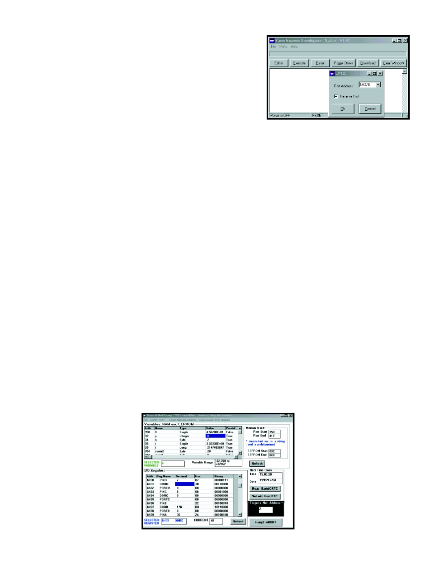
CIRCUIT CELLAR
®
Issue 120 July 2000
29
www.circuitcellar.com
PC’s printer port, sometimes the
printer port doesn’t have enough
power for this. The problem usually
occurs during device programming as
the error “Setup returned invalid
data”. I power my development board
with a separate 5-V supply.
You can write the source code for
your programs within the Basic Ex-
press Development program. How-
ever, the integrated text editor lacks
most of the common Windows tools,
like cut and paste, so I used Notepad
to create the BASIC source code file.
After you create a text file (with a
.Bas extension) containing your
source code, enter the editor mode of
the BasicX Express Development
program and open the file to load this
program. The built-in text editor
works fine for minor editing.
This source code must be associ-
ated with a project file, so use “Save
project as” to make an associated
project file. You should use the
project menu in File if you want to
add other BASIC files (like library
code) to this particular project.
Then, you can compile your project
using the compile menu. If the BasicX
development board is connected to
the printer port, you can select “Com-
pile and run”, which downloads the
code to the development board at the
end of a successful compilation.
The BasicX compiler is the slowest
I’ve encountered using my 233-MHz
Pentium. Although NetMedia com-
pares BasicX to Visual Basic, it
doesn’t check syntax when editing,
yet halts while compiling if it discov-
ers an error. Other code errors
aren’t reported until you recom-
pile, so check the code as you
write. There are many syntacti-
cal differences among BasicX and
Visual Basic or QuickBASIC.
Programs I’ve written use
40% of the 32-KB available
memory, and take a couple min-
utes to compile. I like many of
the BasicX features, so I accept
the limitations.
THE NETSNOOP BDM
Because the BasicX device has
RS-485 multi-drop networking
capability essentially built-in, I
used this capability to imple-
ment a background debug mod-
ule. I wanted a PC as the host,
but because it doesn’t have
built-in RS-485 capability,
something had to be added
between it and the target
BasicX board. I added an un-
modified NetMedia develop-
ment board that I owned.
Figure 1 is a diagram of the
interconnection among the PC,
NetMedia development card,
and the target BasicX board. Although
the 19,200-bps data link between the
PC and the NetMedia development
board is not fast, it only takes one
second to refresh the host PC with
the memory or register contents of
the target BasicX device.
If the BasicX board you’re designing
doesn’t include RS-485 network ca-
pacity, the network components
would have to be added to your board
to use this BDM. This comprises only
one IC and a few resistors, costing
about $2. Refer to Figure 1 in Part 1
for the specific components of the RS-
485 network. If your design requires a
RS-485 network, the BDM should still
work. If your design performs many
data transfers on the network, the
BDM will be sluggish, or it will slow
your target application, because they
share a network bandwidth.
Before wading through more details
about the BDM, you’re probably curi-
ous about its capabilities. Photo 2 is a
screenshot of the BDM host applica-
tion running on a PC. What follows is
a detailed description of each feature.
The upper window is the variables
window. As a true symbolic debugger,
the BDM host program reads a map
file generated automatically when you
compile your target board’s program,
and displays your program variables
by name and type. Whether or not the
variable is persistent (EEPROM-based)
is also shown. You can change the
value of a variable in your target
board’s program by entering a new
value. A small text box shows the
valid numeric range for that type of
variable. The RAM and EEPROM
memory ranges used by your
program’s variables are displayed to
the right of the variable window.
I didn’t want the host PC to hog
the network, so I put a refresh button
in the variable window. Variable val-
ues are only read in the target board
when that button is pressed. Con-
versely, modifications of a variable
are sent to the target immediately. It’s
prudent to steer clear of the RAM and
EEPROM that are reserved by the
BasicX interpreter, so this window
doesn’t allow access to those areas.
The lower window is for the
I/O registers. In Atmel’s AVR
processors, the I/O and control
registers are mapped into both a
register and memory space. I use
this feature to access the regis-
ters through the network in the
same way as the variables. This
window displays most of the
registers, except the SPI and
UART registers, because the
target program crashed when I
tried accessing them. You can
access the physical I/O ports (A,
B, C, D) from this window, but
playing with some of the other
registers may crash the BASIC
Photo 1—
The BDS user interface screen is sparse, most of the
functions are accessible via the editor button. Here is the dialog
box from which you select the correct printer port for downloading.
Photo 2—
The three main functions of NetSnoop have their own
windows. Display and modification of variables, I/O registers, and the
real-time clock are done in their respective windows.

30
Issue 120 July 2000
CIRCUIT CELLAR
®
www.circuitcellar.com
too, and should be copied to your
Windows\System folder. If you are
worried about overwriting your exist-
ing DLL or VBX files, check if any of
these files have the same name as
your existing files. The
vbrun300.dll
file probably exists on your system,
because many programs use this Vi-
sual Basic 3 runtime package.
Connect everything as shown in
Figure 1. To use the BDM, you must
have an RS-485 network port present
on your target board. As mentioned
earlier, this may mean adding a few
components.
In your target board’s program
code, you may enable network func-
tionality using:
Call OpenNetwork(x,y)
where x is the network port address
you want to assign to the target and y
is the group address (use 0 unless you
are using groups).
You can pick any unique network
address within the range of 1–65, 279.
I assigned address 0 to the NetMedia
development board used by NetSnoop,
so don’t pick 0 for your target board!
As a side note, I couldn’t get
BasicX devices to perform network
functions by using NetMedia’s
project-chip menu item and selecting
network enable. There are many other
functions here, and I haven’t been
able to enabled extended I/O and
RAM from this menu, either. I get
around the former problem using the
BasicX code mentioned above. To
enable the external RAM or I/O
mode, I use the following BasicX com-
mand, which directly accesses the
90S8515’s MCUCR register and sets
the external SRAM enable bit:
Register.MCUCR =
register.MCUCR or 128
I run NetMedia’s software
on several computers and
have never had luck with the
chip menu options. Appar-
ently I’m not the only person
experiencing problems, I’ve
seen questions about this on
Delphi’s BasicX forum. I as-
sume the problem stems from
a glitch in reading the
.PRF
file that contains these options.
Now you’re ready to power your
target board and the NetMedia devel-
opment board, and start the NetSnoop
program. To avoid confusion, first the
NetSnoop program will prompt you
for your target board’s network ad-
dress. Then, it will prompt you to
navigate to the folder containing the
source code for your target board’s
program, and pick the map file (
.mpx)
corresponding to the program running
on the target board. The map file
maps RAM and EEPROM addresses to
the named variables displayed in the
variable window.
Finally, it will remind you to click
on the COM port menu item to tell
NetSnoop which PC COM port you
are using to connect to the NetMedia
development board.
At this point, you can use the vari-
ous windows in NetSnoop to examine
what’s happening inside the BasicX
device on your target board. Figure 2
shows a sample of the network activ-
ity associated with this. This BDM
doesn’t support breakpoints or single
stepping, because these features
couldn’t be implemented using only
the network port for BasicX access.
HINTS AND KINKS
I hope that Ham operators will
pardon me for borrowing the title of
this section from one of their jour-
nals. The following are miscellaneous
topics that are useful to BasicX users.
The first topic is using the BDM
for development. When building a
BasicX project, you may have an idea,
but haven’t written the drivers for
user I/O yet. In other words, you don’t
have the code for command and nu-
meric data parsing, numeric-to-ASCII
conversion, and so on. Thus, it’s diffi-
cult to debug the code needed to per-
form your project’s core operations.
program that runs on your
target board. Refer to Atmel’s
90S8515 datasheet for further
details about accessing the
register files.
I included a real-time clock
window so the user can dis-
play its value on the target
board, and set it to match the
host PC’s time.
Although the BasicX network pro-
tocol runs as a background task, your
program can do something that kills
or suspends the network response.
Consequently, I added an abort button
to recover if the BDM program hangs
while awaiting response from a target
board. This also can occur if you don’t
set the network address value in
NetSnoop the same as the address
assigned to the target board.
BasicX has commands to set and
read I/O pins by pin number, but the
Atmel 90S8515 labels its I/O ports
A–D. I included “Show BasicX CPU
diagram” as a menu item, which pops
up a diagram of the chip to relate pin
numbers to actual port designations.
This bitmap’s image constitutes 75%
of my host program. If I used my new
Visual Basic 6 compiler for this pro-
gram, I could have embedded a fancy
PDF or JPEG image, which is
smaller. However, that would have
meant a 32-bit program, requiring
Windows 95 or 98.
USING NETSNOOP
To use the BDM, first download
the BDM firmware into NetMedia’s
development board (or homebrewed
equivalent). Unzip the
Firmware.zip file to find files
Netsnoop.bxb and Netsnoop.prf.
Using NetMedia’s development
software, download
Netsnoop.bxb
file into the development board. I
assume you’ve used the BasicX sys-
tem, and read NetMedia’s instruc-
tions about how to enable the COM2
port on the development board, and
how to set the network termination
jumpers on the development board
and target board.
Unzip the
VB.zip file, copy the
Netsnoop.exe file into a new folder
called NetSnoop, and make a short-
cut. VB support files are in this zip
Host PC
NetMedia BasicX
development board
RS-232
RS-485
BasicX
Target board
COM2
Network
port
Network
port
Figure 1—
Here’s how to connect the various components of the NetSnoop
debug monitor.

CIRCUIT CELLAR
®
Issue 120 July 2000
33
www.circuitcellar.com
Figure 2—
I set the scope up to capture the network activity in-
volved in a read of a byte variable. The first burst is the query to the
remote device and the second is its response. Each burst is 290 µs.
Brian Millier is an instrumentation
engineer in Dalhousie University’s
chemistry department, Halifax, NS,
Canada. He also runs Computer In-
terface Consultants. You may reach
him at brian.millier@dal.ca.
In some cases, it’s handy to write a
BasicX core program so that it enters
a loop where it checks for the value of
a variable named command and, if it’s
not zero, jumps to a specific routine
based on that value. Specific routines
can retrieve necessary parameters
from a variable or array, called “pa-
rameter,” and return any output to a
variable or array, called “result.”
When the routine is complete, it sets
the command value back to zero,
indicating that it is ready to accept
another command.
Then, debugging such a program is
easy using NetSnoop. Load the proper
value(s) into the parameter variable
and set the command variable to the
correct value. When the variable re-
turns to zero, it’s finished. The
routine’s return value, if applicable,
will be displayed in the variable win-
dow as the value of the result vari-
able. This method is handy when
working with floating-point numbers,
because it is more difficult to write
the code that deals with the input and
display of these numeric types.
The next issue is using the BasicX
COM ports. You must first open a
queue for each direction (in, out). The
COM routines are interrupt-driven
and fill or empty these ring buffers.
The system library manual explains
this. However, it’s not obvious that
you must allocate a minimum 10-B
queue even if you expect to buffer
only one character at a time. Eight of
these bytes are used for pointers. I’m
stingy with allocating RAM, because
it’s often in small quantities in micro-
controllers and I’ve had problems
allocating only a 5-byte COM
buffer for a port I assumed
would receive small packets.
The third topic is reading
and writing I/O ports directly.
Although you can read and
write individual I/O pins
using the BasicX GetPin func-
tion or PutPin procedure, if
you want to read or write all
port bits, use the register
command. It’s documented in
the operating system manual,
but isn’t listed in the system
library manual.
All of the registers are
accessible by name, and there is a
special purpose register list in
NetMedia’s documentation. You can
also get this information from
Atmel’s 90S8515 datasheet (pages 12–
13). I had trouble because I assumed
there was only one data register for a
given I/O port, which is typical of
other microcontrollers. For the
90S8515, there’s a data register that
holds the data for output mode, and
an input pins register that’s for the
90S8515 used when the port is set for
input mode. Of course, there also is a
data direction register, which must be
used to set the proper I/O direction.
The fourth topic is using the SPI
port with external peripherals. If you
plan to use the SPI port on the BasicX
chip for anything other than as the
program (EEPROM) memory inter-
face, you’ll have to use the OpenSPI
procedure. I recommend that you refer
to Atmel’s 90S8515 datasheet (pages
33–36), because the procedure’s docu-
mentation isn’t thorough.
BASICALLY DONE
I hope this series encouraged you to
try BasicX, or helped you program.
You may also want to consider
NetMedia’s device that competes
with the PIC stamps.
I

34
Issue 120 July 2000
CIRCUIT CELLAR
®
www.circuitcellar.com
115 VAC, to
Go, Please
FEATURE
ARTICLE
t
If you have a small
appliance that needs
a portable power
source, then you’ll
want to pay attention
to what Tom has to
say. When it came
time to upgrade an
earlier project, using
a PIC to drive the
portable inverter was
the obvious choice.
his project’s
roots date back to
1974 when I lived in
France and bought an 8
″
telescope with two 115-VAC 60-Hz
synchronous motors. This was fine for
the U.S. market, but not in a country
where the AC power is 220 V, 50 Hz.
I soon built a 60-Hz inverter that ran
off a 12-V NiCad battery. Small
enough to fit in the base of the tele-
scope, it generated 220 V to drive the
two motors in series. Its frequency
was set by an RC multivibrator and
could be adjusted to the correct rate
to cancel earth’s rotation.
Years later I wanted to replace the
12-V battery with a 6-V gell cell but
didn’t want to redesign the inverter,
so I built a crystal-controlled 60-Hz
square-wave generator. I used 4000
series CMOS logic because it isn’t
fussy about its supply voltage.
OUT WITH THE OLD
Instead of using 1970’s technology,
I could do the same job with a PIC
microcontroller in half the space. I
also discovered I needed a 12-V bat-
tery to power the CCD camera and
the portable B&W TV, which I use to
show the wonders of the universe to
children. It made sense to power ev-
erything from the same battery and
reinstate the original 1974 inverter.
I’m not using one of those $3000
CCDs. I have an $80 low-light CCD
camera board designed for surveil-
lance. Mounted without its lens at the
prime focus of my telescope, it gives
amazing views of the moon, planets,
and double stars, particularly if you
tape the output and freeze-frame to
eliminate atmospheric turbulence.
WHAT ARE WE AIMING FOR?
Assuming you want a rectangular
output to emulate a 60-Hz sine wave,
the wave’s peak value is
√2
times the
RMS (root mean square) supply volt-
age. That is, 115 VAC swings from
163 V to –163 V during each cycle. If
you use a square wave with the same
peak voltage, you would have 163
VRMS. To get 115 VRMS, use a lower
peak voltage or rectangular pulses
shorter than a half cycle of the AC. A
pulse whose width is one-quarter of
the AC period gives the correct RMS
voltage (see the “Peak, RMS, and
Mean” sidebar). The waveform in
Figure 1 is similar to a sinewave. It
has the same peak and RMS voltages
as the original so it will drive a nor-
mal step-down transformer and give
the correct output if you rectify it.
Unless you fancy winding your
own, the only practical 60-Hz inverter
transformer is a step-down power
transformer running backwards. There
is 12 to 14 V going in when running
from a 12-V lead-acid battery. You
have 10.5 V to work with if you allow
a ~1.5-V voltage drop in the switching
transistors and the current sense resis-
tor. Because you want 163-V peak,
you need a transformer with a turns
ratio of at least 16:1. Remember that
because a power transformer's rated
output voltage is measured under
load, its true turns ratio is lower than
Tom Napier
Drive a Portable Inverter
with a PIC16C54
Figure 1
—Here, 4.2-ms bipolar pulses supply as much
RMS power as regular AC. Small changes in the pulse
width stabilize the effective output voltage.

CIRCUIT CELLAR
®
Issue 120 July 2000
35
www.circuitcellar.com
you assume. Because you are doing a
step up, you need an even higher turns
ratio to allow for resistive losses.
I tried a 3-A, 12.6-V center-tapped
transformer, but the inductance was
too low. A split-primary transformer
works if you connect the two 115-V
windings in series. I used a 30-VA
transformer whose two 10-V second-
ary windings were rated at 1.5 A. The
turns ratio was approximately 19:1,
and I used a Tamura PL30-20 (from
Digi-Key, part number MT3123).
PUTTING IT ALL TOGETHER
As Figure 2 shows, two power
transistors that are switched by two
PIC output pins drive the secondary
windings. To get enough current gain,
I used TIP122 Darlington transistors
even though their on-voltage and
power dissipation are higher than that
of single transistors. Power FETs also
work, but they drop more volts than
Darlingtons unless you buy expensive
ones. Also, you need more drive volt-
age than the PIC can supply to turn
them on. The snubber network of two
diodes and a zener saves the switching
transients from damaging the power
transistors. The 10-
Ω
resistor limits
the peak current through the zener.
It took a few hours to put a ’16C54
on a board, write the 60-Hz pulse
generator code, and hook up the out-
put transistors. The obvious solution
to get a soft turn-on was to start with
narrow pulses that gradually widen.
But if the pulse width is modulated, it
can also regulate the output voltage.
After all, you don't want the AC out-
put changing with the battery voltage
or the load you apply.
Because the transformer has an
effective 300-
Ω
output resistance, the
raw output voltage drops steeply with
load current. Ideally the control
mechanism would maintain a con-
stant RMS output voltage, but that
requires multiplying the mean and
the peak output voltages. Although
less satisfactory, I chose a simpler,
constant mean voltage control loop.
My crystal frequency was 38.4 kHz,
so the PIC executed 9600 instructions
per second. Why not use an old-fash-
ioned “bang-bang” control system?
Before second-order loops and fuzzy
logic, everything ran from switch
closures.
One input bit tells the PIC that the
output voltage is either too high or
too low. As a result, the PIC makes
the drive pulses narrower or wider.
Now you can use an optocoupler to
isolate the PIC and battery from the
high-voltage output. The output volt-
age will ramp up and down around the
desired value, but this shouldn't mat-
ter unless you are driving a filament
bulb, which will flicker.
I sketched software to read the
control bit, increment and decrement
a width register, and set the cycle
timing accordingly, but it was slow.
Too much of each cycle was devoted
to computation; during the pulse on
or off time, it limited the control
range. Also, the minimum change in
pulse width was one loop time, about
4% of a half cycle.
USE SMARTER SOFTWARE
Part of the trouble was that the
increment/decrement process needed
to test the result to keep the width
Figure 2
—The PIC microcontroller
generates variable width transistor
drive pulses under the control of on/
off feedback from the AC output. A
current-sensing circuit turns the
system off if anything goes wrong.
Partial flow chart
Loop1: Set width N (minimum width)
Call positive pulse
Call negative pulse
Test control bit
If set go to self
Else
Loop2: Set width N+1
Call positive pulse
Call negative pulse
Test control bit
If set go to previous loop
Else
Loop3: Set width N+2
Call positive pulse
Call negative pulse
Test control bit
If set, go to previous loop
Else
:
:
LoopX: Set width N+M (maximum width)
Call positive pulse
Call negative pulse
Test control bit
If set go to previous loop
Go to LoopX, can't get any wider
Listing 1
—The output pulse width is a function of where you are in the flowchart. Each complete cycle uses
pulses wider or narrower than the last unless you are at one or the other end of the range.

36
Issue 120 July 2000
CIRCUIT CELLAR
®
www.circuitcellar.com
PEAK, RMS, AND MEAN
When measuring AC and DC voltages, compare their power generating
effects. Thus, a resistor will get just as hot if you connect 115 VAC or
115 VDC.
Because power is the voltage squared, divided by the resistor value, you
calculate AC power by squaring the instantaneous voltage and averaging
the result over a complete cycle. To get an equivalent voltage, calculate
the square root of the mean value, which is the RMS (root mean square).
This process works for any waveform.
To compare power accurately, you should always use a true RMS meter,
which squares and adds internally. It too will give inaccurate results if the
input voltage spikes exceed its dynamic range. The power in a rectangular
pulse is simply the voltage squared, multiplied by the on-time ratio. If the
162.6-V pulse is on 50% of the time, the power in a 1-k
Ω
resistor is 13.225
W, the same as if you powered the resistor from a 115-VAC source. The
RMS voltage of a sinewave with no harmonics is its peak voltage divided
by the square root of two. If you full-wave rectify this sinewave and calcu-
late the average, you get a DC voltage that is 2/
π
multiplied by the peak
voltage. Consequently, the RMS voltage is 1.11 times this mean voltage.
Most multimeters use this relationship to measure AC voltage, but if
the input is not a sinewave, they give an incorrect reading. For example,
the 162.6-V, 50% on-time pulses have an 81.3-V mean rectified voltage. A
simple AC meter will indicate this as 90.3 V even though the actual RMS
voltage is 115 V.
A NPN transistor’s base is con-
nected to the resistor to sense over-
load. An RC filter prevents current
spikes from triggering a shut-down,
but if an overload continues for more
than a few milliseconds, a PIC input
pin is pulled low. This shuts off the
outputs and resets the program. After
a 2-s delay, the oscillator restarts with
its narrowest on time. A persistent
output short will cause a series of
narrow output pulses at 2-s intervals
and shouldn’t harm anything.
SENSING THE OUTPUT
Let’s discuss the circuit hooked up
to the output. This circuit drives the
width control bit of the PIC via an
optocoupler. The optocoupler isolates
the AC output from the rest of the
circuit, allowing the transformer out-
put to float with respect to ground.
This circuit must act simultaneously
as a power source for the sensing
system and as an output voltage mea-
surement device. But, these require-
ments are incompatible. Because the
output is connected via a large resis-
tor, any change in the load current
changes the voltage sensed.
So, I measured the total current
with a small series resistor and pow-
ered the circuit from a zener diode,
which is free to pass more or less
current when the load changes. The
5.1-V zener also acts as the voltage
reference. Fortunately, an AC supply
doesn’t need the precision regulation
that a DC supply needs. A trimmer
sets the correct output voltage.
The LM311 comparator derives a
1.6-V reference from the zener diode.
Its other input gets a voltage that is a
function of the current flowing
through the 10-k
Ω
, 5-W resistor
across the AC output. This configura-
tion was chosen to avoid using a high-
voltage rectifier and filter capacitor.
Don’t be tempted to run the inverter
without a load across the 47-µF ca-
pacitor, it may explode!
When the output voltage rises, the
sense current increases and turns on
the comparator’s output transistor.
This activates the optocoupler and
within bounds. Now there are only
two alternatives at the end of each
AC cycle. Depending on the state of
the control bit, the next two pulses
(one positive and one negative) are
either wider or narrower than the last
two. To preserve output symmetry,
the positive and negative pulses in
each cycle have the same width.
My solution: 60 possible pulse
widths are each set by a separate piece
of code. Limit testing is free, the wid-
est routine jumps to itself or to the
next one down. Similarly, the narrow-
est routine jumps to itself or the next
one up. Part of the resulting flowchart
is shown in Listing 1.
The pulse widths are governed by
how far you jump down a string of 60
no-operation instructions after turn-
ing on an output. At the end of the
string, the output turns off and you
jump into another string of NOPs.
The sum of the strings equals one
period of the AC output, less time for
the other necessary instructions. The
width resolution is one instruction or
1/80 of a half cycle. An over-current
sense bit is tested at the end of each
pulse to determine if the fault routine
should be called.
Each control routine sets a width
and calls the subroutines, which de-
termine the positive and negative on
times (the code looks easy, but it’s
tricky to get the timing correct).
Fifty-nine width control routines fit
in the 512 instruction limit of the
16C54. Because only four I/O pins are
used, this design could be imple-
mented in an 8-pin PIC.
BACK TO THE HARDWARE
I built a demo unit on a 5
″
× 5
″
aluminum plate that serves as a heat
sink for the output transistors. The
plate carries the transformer and the
controller board. The current limit
sensor is a 0.12-
Ω
resistor in series
with the emitters of the transistors (I
wound one from 4
″
of Eureka wire).
Power (W)
Ipk (mA)
Vpk (V)
Width (%)
Vrms (V)
5
59
184
46
125
10
118
157
54
116
15
177
131
65
105
20
235
104
82
94
Table 1
—Even though
the mean output
voltage is stabilized,
the true (RMS) output
voltage changes with
the load.

CIRCUIT CELLAR
®
Issue 120 July 2000
37
www.circuitcellar.com
tells the PIC to lower the drive pulse
width. The 470-k
Ω
resistor applies
positive feedback around the compara-
tor, making it switch cleanly. Because
turning on the optocoupler narrows
the output pulses, the oscillator starts
correctly even without output voltage
to drive the comparator.
I’d hate to analyze the formal sta-
bility of the feedback loop, but the
slow output change forced by the
software makes it the dominant time-
constant. And, the capacitor value
across the bridge rectifier is critical.
With most loads, the pulse width
makes minimum steps up and down.
CALIBRATION
Because the control circuit senses
the mean output voltage and not the
true RMS voltage, the output voltage
will only be correct at one point. Pick
it by adjusting the control trim.
The no-load peak output voltage is
about 210 V and the measured output
resistance is 450
Ω
, so the maximum
output power is less than 25 W.
Let’s assume you want 115 VRMS
at an output of 10 W. Using the
RMS voltage and the power, you
calculate the load resistance at 1332
Ω
. A 450-
Ω
output resistance leaves
a 156.7-V peak voltage. The ratio of
the RMS to the peak voltage is the
square root of the on ratio, so the
latter must be 53.9%. Thus, if you
connect a 1332-
Ω
load, you can set
the output trim to give a 4.5-ms
pulse length. Table 1 shows how the
theoretical output voltage varies
with the power taken. The current
rating of the power transistors lim-
its the output power to approxi-
mately 20 W.
WRAP-UP
The story ends there. This in-
verter supplies nearly 20 W at 115 V.
Its efficiency is only, about 60% and
its output voltage varies signifi-
cantly with the applied load. How-
ever, for many jobs, such as driving
small appliances, this inverter is
good enough.
SOURCE
I warn you that even though this
inverter is battery-driven, it puts out
enough power to give you a nasty
shock. Treat it with as much respect
as you would a 115-V wall outlet.
I
SOFTWARE
The software for this article is
available for downloading from the
Circuit Cellar
web site.
Tom Napier is an electronics consult-
ant who sometimes writes articles.
Lately he has been using mixed ana-
log and digital technology to enhance
space data receivers. One of his hob-
bies is astronomy.
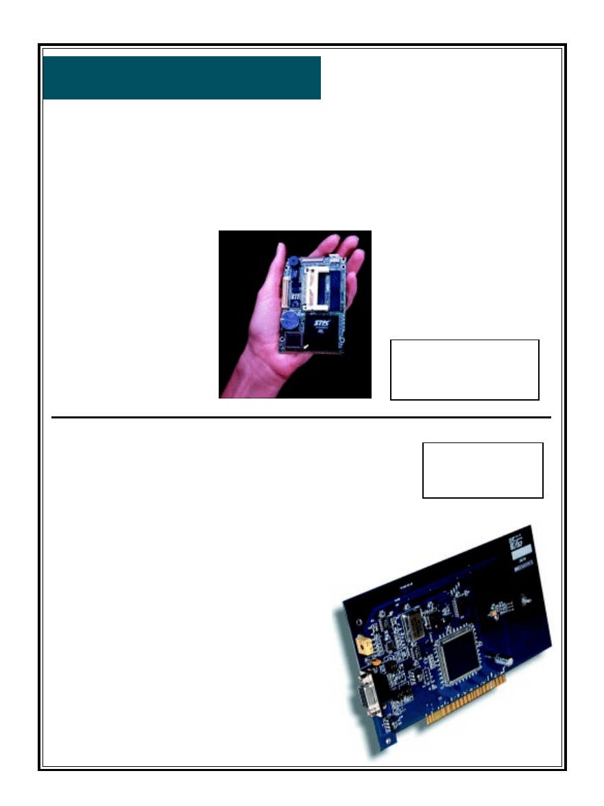
38
Issue 120 July 2000
CIRCUIT CELLAR
®
www.circuitcellar.com
Edited by Harv Weiner
NOUVEAU
PC
PLUG-IN COMPUTER
Advantech Technologies, Inc.
announced the CPC-2245, a 486
processor-based single board com-
puter. The 2.5² × 4² computer is
ideal for applications in portable
test equipment, intelligent access
controls, or as a pluPlug-in Com-
puter
Advantech Technologies, Inc.
announced the CPC-2245, a 486
processor-based single board com-
puter. The 2.5² × 4² computer is
ideal for applications in portable
test equipment, intelligent access
controls, or as a plug-in processor
on an integrator’s board.
The CPC-2245 features 8 KB
cache and 32 MB of RAM. A 10/
100 Base-T Ethernet controller,
PCI slot, SVGA interface with a
64-bit accelerator, two RS-232
serial ports, IDE HDD interface,
floppy disk controller, and one ISA
interface for functional expansion are
included. And one bi-directional
printer port that supports SPP, ECP,
and EPP modes is included. A
CompactFlash solid state disk socket
is provided and Windows CE can be
pre-installed.
Power can be supplied through
a SODIMM socket or an on-board
power connector. Thus, the unit
can be embedded in the user’s
system board or used as a single-
board application. The ISA bus,
HDD, FDD, and parallel interface
are connected to the user’s system
board via a SODIMM socket. A
damaged card can be replaced
within 30 s. This PC is easily
upgraded from 486 to Pentium
without changing the user’s sys-
tem board.
The CPC-2245 as described
sells for less than $400 in evalua-
tion quantities (1 to 9).
Advantech Technologies, Inc.
(949) 789-7178
Fax: (949) 789-7179
www.advantech.com
I
2
C-BUS COMMUNICATIONS ADAPTER
Included are 32-bit Windows DLLs,
giving users an easy software develop-
ment path without requiring specialist
PCI or Windows I/O knowledge.
For new I
2
C users who want a quick
start with the bus, ready-to-run
WINI
2
CPCI Windows 95/98/NT
software provides all the common
I
2
C functions and also includes a
unique real-time I
2
C bus moni-
tor/data-logger for investigat-
ing bus activity. Function
libraries for the user’s appli-
cation software are standard
software.
The PC190 costs $399.
The PC190 is a PCI-format
I
2
C-bus communications
adapter. It uses the Philips
PCF8584 I
2
C-bus controller to
support the full I
2
C communi-
cations protocol, and plugs into
an available PCI slot in a PC.
Bus termination and protection
are all link-selectable, and the
I
2
C configuration and all other
protocol functions are software
controllable.
All I
2
C features are available
under software control includ-
ing data transmission mode
(master/slave, transmitter/
receiver), own slave address,
and SCL clock speed when oper-
ating as a master (1.5/11/45/90
KHz). A transparent real-time
bus monitor program is pro-
vided, and multi-master opera-
tion and associated bus
arbitration are fully supported.
Saelig Company LLC
(716) 425-3753
Fax: (716) 425-3835
www.saelig.com

CIRCUIT CELLAR
®
Issue 120 July 2000
39
www.circuitcellar.com
NOUVEAU
PC
DEVELOPMENT SYSTEM ENCLOSURE
The VersaBox development enclosure from
VersaLogic provides inexpensive protection,
convenience, and portability for a PC/104 or EBX
development system. A connector panel with
cutouts for popular system connectors provides
easy access to I/O signals, and a removable lid
provides access to the processor board. The pro-
cessor board is mounted at the top of the enclo-
sure for easy access during development.
At 9.5
″
× 11
″
× 8
″
, the VersaBox has enough
space to contain all system components—an
EBX single board computer or PC/104 CPU, up
to two PC/104 expansion modules, an ATX-
style power supply, and 3.5
″
hard and floppy
drives. A 5.25
″
CD-ROM drive can be
mounted in an optional cover. The steel enclo-
sure properly supports the SBC for repeated
insertion and removal of PC/104 cards, I/O
cables, and such. without excessive board
flexing or stress. The connector panel accom-
modates VGA, KBD, mouse connectors, four
COM ports, two LPT ports, RJ45 (Ethernet),
two USB ports, sound/mic jacks, reset switch,
two activity LEDs, speaker, and a 50-pin cable
exit slot.
The enclosure simplifies development of
embedded systems by packaging the primary
system components for protection and portabil-
ity. In addition to development use, the enclo-
sure (with lid attached) provides a professional,
attractive appearance for system demos.
The VersaBox costs $125. A complete pack-
age including power supply, cables, and disk
drives is available.
VersaLogic Corp.
(541) 485-8575 Fax: (541) 485-5712
www.versalogic.com
PCI BUS SERIAL I/O CARD
ACCES I/O
Products intro-
duced the PCI-
COM-1S
non-isolated
asynchronous
serial commu-
nications card
for PCI bus
computers.
This card, and
the PCI-ICM-
1S (500-V opto-
isolation),
support RS-422
and RS-485
balanced-mode transmission/reception and provide auto-
matic control of RS-485 drivers for Windows systems. Both
cards provide onboard jumpers to increase the serial data
rate from 115.2 kbps to 460.8 kbps. Buffered asynchronous
communications elements prevent data loss in multitasking
systems while providing 100% compatibility with the origi-
nal IBM serial port.
Termination of receiver inputs to prevent ringing when
the cards are installed at the end of a network is enabled by
onboard jumpers. Jumpers also can provide a bias voltage to
maintain a known zero state when all transmitters are off in
RS-485 networks. The driver and receivers can drive up to
±60 mA on balanced lines and can receive differential inputs
as low as ±200 mV. The driver or receivers perform thermal
shutdown if there are conflicting communications.
When the card is installed, Windows 95/NT will detect it
as new hardware and assign it an IRQ number and base ad-
dress. There are no switches to set or base addresses to as-
sign. After that, the card behaves as a standard COM port at
COM 5.
Menu-driven sample programs and drivers for DOS, Vi-
sual Basic, Windows 3.x/95/98/NT, and LabView, as well as
other utilities, are provided on a single CD for free. These
utilities include a setup program, resource locator, card-
specific DOS and Windows programs, terminal communica-
tion program, and generic interface code.
The PCI-ICM-1S costs $235 and the PCI-COM-1S (non-
isolated) costs $175. Both include the card, manual, and
software.
ACCES I/O Products, Inc.
(858) 550-9559
Fax: (858) 550-7322
www.accesioproducts.com

CIRCUIT CELLAR
®
Issue 120 July 2000
41
www.circuitcellar.com
EPC
R
EAL
-T
IME
PCs
Ingo Cyliax
Real-Time Executive for
Multiprocessor Systems
RTEMS has some
great networking
support features,
this month Ingo
covers those in
more detail and
shows us just what
it takes to get an
i386 RTEMS appli-
cation up and run-
ning. And, it’s easier
than you think!
Part 3: Running i386 RTEMS Applications
l
n the third part
of this RTEMS
series, I’ll look at the
networking support in
RTEMS. As you remember, Real-Time
Executive for Multiprocessor Systems
(RTEMS) is an open-source RTOS that
is available from On-Line Application
Research Corporation (ORA Corp.) for
a variety of platforms and architec-
tures. In this series I have been look-
ing at the i386 port of RTEMS for the
standard AT-compatible board support
package (BSP).
In a nutshell, to get RTEMS, you
download the sources from
ftp.rtems.com, as well as the GNU-
based cross compiler for your archi-
tecture. In my case, I downloaded the
RPMs for Linux.
In Part 1, I walked through the
steps to build RTEMS based on a
snapshot. At the time I was writing
this installment, the 4.5.0 beta release
was out, so I gave it a whirl to take
advantage of the examples.
At the time of writing, 4.5.0-beta
1c is almost complete. I downloaded
the i386 cross compiler and
binutils
for Linux. These install in the direc-
tory
/opt/rtems.
I then downloaded the kernel
sources and the sources for the net-
work demonstration utilities. I
unarchived these in the directory
/
opt/rtems/Tools and entered:
cd /opt/rtems/Tools
tar xzf rtems-4.5.0
beta1c.tgz
tar xzf netdemos-4.5.0
beta1b.tgz
I created the build directory,
mkdir
/opt/rtems/Tools/ build-4.5.0
beta1c, set the search path of my
shell to pick up the cross compiler, and
ran the configuration process, followed
by a build and install (see Listing 1).
This compiles the kernel and li-
braries, as well as some test programs
to make sure everything builds and
links properly. The libraries and pro-
totype
makefiles are installed in the
pc386 directory under /opt/rtems.
Now you’re ready to play around with
the networking system.
FEATURES
As I mentioned last month,
RTEMS has a complete TCP/IP net-
work stack, including several network
drivers. The network drivers imple-
ment the link layer protocol. This is
the layer where the packets (or
frames) get sent across wires, fiber, or
in some cases, air. Because Ethernet is
the most common link layer protocol
besides PPP used for TCP/IP, there are
several choices of Ethernet drivers.
In many cases, the network drivers
are specific to BSPs. The pc386 BSP
supports several network cards—
Wester Digital’s wd8003, 3Com’s
3c509, and the NE2000. It’s interesting
to note that these are prototypical
drivers for older models of Ethernet
cards. However, newer versions from
the same company generally imple-
ment the same or similar interface,
and these drivers work with such
newer chips. In particular, the NE2000
device driver works with almost all
NE2000-compatible network cards
from different manufacturers.
There are some BSPs other than
the pc386 that contain their own
implementation of network drivers
for Ethernet chips. The i386ex BSP
contains a network driver for the
Intel 82596 Ethernet chip, and the
MC68360 and MPC860 BSPs have

42
Issue 120 July 2000
CIRCUIT CELLAR
®
www.circuitcellar.com
drivers for all of their on-chip
Ethernet interfaces.
But as the RTEMS matures and
common drivers are needed across
BSPs, the drivers are generalized and
included in the
libnetchip library.
Currently, there are only two Ethernet
drivers implemented there—the driv-
ers for the DEC 21140 and the SONIC
Ethernet chipsets.
The DEC 21140 is a 10/100-MBps
PCI-based chipset that is commonly
found in many systems (e.g., PC and
Macintosh). The National Semicon-
ductor SONIC chip is also found on
many PC and embedded systems be-
cause it is so easy to integrate.
The
libnetchip drivers don’t
access the chips directly, but rely on
BSP-based drivers to access the regis-
ters and memory on the chips. Also, a
BSP-based attach routine is needed to
detect whether or not the chip is
available in the system before initial-
izing it. This is necessary because
each platform may have a different
way to access I/O buses in the system.
Finally, the PPP driver can be used
with any of the serial port drivers that
are available from RTEMS. The PPP
driver is an adaptation of the PPPD
system driver that can be found in
many Linux and Unix systems. It is
capable of acting as a PPP client or
server and implementing PAP and
CHAP authentication mechanisms, as
well as header compression and all
standard PPP features.
Besides having drivers for several
different Ethernet chips, the network-
ing library also contains implementa-
tion for many standard protocols that
are used for dynamic host configura-
tion (i.e., Boot Protocol [BOOTP] and
Dynamic Host Configuration Protocol
[DHCP]). Both of these protocols can
be used to initialize the network pa-
rameters such as hostname, Internet
address, gateway address, and various
servers from a configuration server.
The server either dynamically as-
signs hostnames and addresses from a
list of available hosts or uses the
nodes’ hardware address to look up
the information in a table. At my
house, I have an ISDN router that can
be configured to assign a range of IP
addresses via DHCP or BOOTP to

CIRCUIT CELLAR
®
Issue 120 July 2000
43
www.circuitcellar.com
Listing 2—
A wrapper used by an RTEMS application to run a Unix program under RTEMS. It emulates some of
the missing system calls and library functions and collects the command line arguments for the program TTCP.
#include <stdio.h>
#include <string.h>
#include <ctype.h>
#include <rtems.h>
#include <rtems/rtems_bsdnet.h>
#include <rtems/error.h>
#include <sys/types.h>
#include <sys/socket.h>
#include <netinet/in.h>
#include <netdb.h>
#include <sys/time.h>
/*
* Glue between UNIX-style ttcp code and RTEMS
*/
int rtems_ttcp_main (int argc, char **argv);
static int
select(int nfds, fd_set *readfds, fd_set *writefds, fd_set *exceptfds,
struct timeval *timeout)
{
rtems_panic (select());
}
static void
(*signal(int sig, void (*func)()))()
{
return 0;;
}
#define _SYS_RESOURCE_H_
#define
RUSAGE_SELF
0
/* calling process */
#define
RUSAGE_CHILDREN
-1
/* terminated child processes */
struct rusage {
struct timeval ru_utime;
/* user time used */
struct timeval ru_stime;
/* system time used */
int ru_maxrss;
/* maximum resident set size */
int ru_ixrss;
/* currently 0 */
int ru_idrss;
/* integral resident set size */
int ru_isrss;
/* currently 0 */
int ru_minflt;
/* page faults not requiring physical I/O */
int ru_majflt;
/* page faults requiring physical I/O */
int ru_nswap;
/* swaps */
int ru_inblock;
/* block input operations */
int ru_oublock;
/* block output operations */
int ru_msgsnd;
/* messages sent */
int ru_msgrcv;
/* messages received */
int ru_nsignals;
/* signals received */
int ru_nvcsw;
/* voluntary context switches */
int ru_nivcsw;
/* involuntary context switches */
};
int
getrusage(int ignored, struct rusage *ru)
{
rtems_clock_time_value now;
static struct rusage nullUsage;
rtems_clock_get (RTEMS_CLOCK_GET_TIME_VALUE, &now);
*ru = nullUsage;
ru->ru_stime.tv_sec = now.seconds;
ru->ru_stime.tv_usec = now.microseconds;
ru->ru_utime.tv_sec = 0;
ru->ru_utime.tv_usec = 0;
return 0;
}
static void
Listing 1—
In a nutshell, this is how you configure and build RTEMS libraries under Linux or other Unix-like systems.
cd /opt/rtems/Tools/build-4.5.0-beta1c
export PATH $PATH:/opt/rtems/bin
../rtems-4.5.0-beta1c/configure prefix=/opt/rtems target=i386-rtems en-
able-rtemsbsp=pc386 make
make install
(continued)

44
Issue 120 July 2000
CIRCUIT CELLAR
®
www.circuitcellar.com
to implement small embedded RAM-
and ROM-based file systems with
RTEMS. It’s also possible to imple-
ment handlers for parts of the file
systems. These handlers would then
implement the various file system-
related calls. For example, NFS is
implemented using the file system
handlers.
The web server distributed with
RTEMS is an open-source web server
from GoAhead. It’s clever because it
supports its own set of handlers,
which are interpreted at the URL
level. You can tell it to handle re-
quests for resources by implementing
it as a subroutine. This allows you to
implement forms in the embedded
web server. The default, of course, is
to retrieve web pages from the inter-
nal file system.
The web server also implements an
embedded subset of JavaScript. This is
a scripting language that is used on
the server side. The script is executed
when the page is accessed. The output
from the script is sent onto the web
browser. This is another way dynamic
web pages can be implemented.
Using embedded web servers that
generate web pages dynamically is a
general way to implement user inter-
faces to network-aware embedded
systems. Any workstation or laptop
that has a web browser, such as
Internet Explorer or Netscape, can
access the embedded system over the
network. Instant GUI, no display nor
front panel needed!
Well, that’s the whirlwind tour of
RTEMS networking. Now, let’s look
at a couple of network apps that come
with the demo kit. Besides testing the
basic networking interfaces of
RTEMS, some are useful to illustrate
how to configure and implement net-
work applications.
A FEW NETWORK APPS
The most basic application is the
netdemo application. This program
implements basic network functions.
It provides a TCP/IP-based echo server
that can be accessed from the network
via telnet. Also, there is a network
statistic display that can be called up
from the console. Photo 1 shows what
the netdemo prints out upon startup.
Finally, there are server imple-
mentations for File Transfer Protocol
(FTP) and HTTP. FTP allows clients
to transfer files to and from the
RTEMS. HTTP is the protocol used
by web servers so, in a sense, the
HTTP server is a small embedded
web server.
You may have noticed that the last
two implementations deal with files.
RTEMS implements the standard
POSIX API for dealing with file sys-
tems. Although not all embedded
systems have disk drives, it’s possible
network nodes to my private home
network. Tackling it this way works
well because that means I don’t need
to manually configure every piece of
hardware that I want to hook up to
my network.
Besides all of the network configu-
ration protocols, the RTEMS system
also supports a popular network file
system—the NFS protocol used by
Unix systems. There also are NFS
implementations available for Win-
dows machines and many network-
aware RTOSs.

CIRCUIT CELLAR
®
Issue 120 July 2000
45
www.circuitcellar.com
ment to TTCP. Some of the code may
migrate to the
libc support routines
someday. This program may be dis-
tributed and used for any purpose. I
ask only that you leave the following
author information intact and docu-
ment any changes you make: W. Eric
Norum, Saskatchewan Accelerator
Laboratory, University of Saskatch-
ewan, Saskatoon, Saskatchewan,
Canada, eric@skatter.usask.ca.
A transfer rate of 912.91 kbps is
respectable for 10-MBSPS ethernet.
Especially considering that the
RTEMS system was using an ISA bus-
based NE2000-compatible Ethernet
card. NE2000 network cards are effec-
tive because they are compatible, yet
they are not known for performance.
The final program is a small web
server implementation. It sets up the
network and starts the GoAhead web
server with a small set of HTML pages.
What’s neat about this program is that
it uses the
Untar FromMemory()
function.
Tar is an archive program
popular with Unix systems. It stands
for tape archive and was used to
archive files to and from tape. Today
it is more popular as an alternative to
the common
Zip archive format.
The web page (index.html) is tar’ed
into an archive (tarfile) by the com-
mand
tar cf tarfile index.html.
This
tarfile image is then linked
to an object module with the GNU
linker:
i386-rtems-ld -r -o $(ARCH)/
temp.o $(ARCH)/init.o -b bi-
nary $(ARCH)/tarfile
The linker adds a few variables to
the object,
_binary_start,
_binary_end and _binary_size,
that point to the start and end to indi-
cate the image size. The main applica-
tion is then linked to this module, and
the memory region can be used by the
application (see Listing 4). This rou-
tine is the initialization task for the
test program. Also, don’t forget to
change the IP addresses.
When the application starts, the
network is initialized and the in-
memory tarfile start and size are
passed to the
Untar_FromMemory()
function. This function decodes the
Listing 2—
Continued
rtems_ttcp_exit (int code)
{
rtems_task_wake_after( RTEMS_MILLISECONDS_TO_TICKS(1000) );
rtems_bsdnet_show_mbuf_stats ();
rtems_bsdnet_show_if_stats ();
rtems_bsdnet_show_ip_stats ();
rtems_bsdnet_show_tcp_stats ();
exit (code);
}
/*
* Task to run UNIX ttcp command
*/
char *__progname;
static void
ttcpTask (rtems_task_argument arg)
{
int code;
int argc;
char arg0[10];
char *argv[20];
(remaining code available for download)
Listing 3—
TTCP is a TCP/IP test and benchmark utility. It measures the maximum TCP/IP channel band-
width between two TTCP running tasks. In this case, one is running on an RTEMS system (P133 with
NE2000 Ethernet) and the other runs on my laptop (P166 with PC Card Ethernet).
hugo 100% ./ttcp -t -s 192.168.69.97
ttcp-t: buflen=8192, nbuf=2048, align=16384/0, port=5001 tcp ->
192.168.69.97
ttcp-t: socket
ttcp-t: connect
ttcp-t: 16777216 bytes in 17.95 real seconds = 912.91 KB/sec +++
ttcp-t: 2048 I/O calls, msec/call = 8.97, calls/sec = 114.11
ttcp-t: 0.0user 0.4sys 0:17real 2% 0i+0d 0maxrss 0+2pf 0+0csw
Listing 4—
A web server test program. All you need is a set of files embedded as a tar image in the execut-
able, then initialize the network, un-tar the files, and start the web server.
/* Init
*
* This routine is the initialization task for this test program.
*
* Dont forget to change the IP addresses
*/
...
#include system.h
#include <errno.h>
#include <time.h>
#include <confdefs.h>
#include <stdio.h>
(continued)
Another application is the TTCP
program. Test TCP is a small standard
test program in the Unix community
that tests the transfer rate of the TCP/
IP stack. What is interesting about this
RTEMS application is that the code
hasn’t changed from the Unix version.
If you remember, RTEMS is
POSIX-compatible. This means you
can compile and implement almost all
Unix programs that are programmed
against the POSIX API. In this case,
there is a small wrapper that can be
seen in Listing 2. This is linked with
the Unix version of the TTCP pro-
gram. There are some warning mes-
sages that come up during the
compile. But it does work, as you can
see in Listing 3, where the output of
TTCP is running on my laptop, which
is talking to the TTCP running on my
RTEMS test bed.
A collection of hacks, glue, and
patches provide a Unix-like environ-

46
Issue 120 July 2000
CIRCUIT CELLAR
®
www.circuitcellar.com
Listing 4—
continued
archive and stores the individual files
in the in-memory file system where
they can be accessed by standard li-
brary routines like
open() and
read()/write(). The web server is
then started, and you can access web
pages over the ’Net.
CONFIGURING
I mentioned that the RTEMS net-
working library has support for DHCP
and BOOTP, which can be used to
configure the network parameters
needed by the protocol stack. Besides
DHCP and BOOTP, I can also config-
ure the network parameters by hand
by using the
networkconfig.h file
in the netdemo’s suite of programs.
networkconfig.h contains vari-
ous data structures, configured so the
network code in RTEMS can configure
itself once it’s started. If you want to
use BOOTP, it is straightforward. You
simply put a define at the top of the
file
#define RTEMS_USE_BOOTP.
The default network interface type
is defined in the BSP header file
/opt/
rtems/pc386/lib/include/bsp.h.
As shipped by the system, the de-
fault is the DEC 21140 driver. How-
ever, I changed it to use the NE2000
network card. This is done by adding
lines to the
bsp.h file (see Listing 5).
This may work in theory, but the
NE2000 drive assumes that the de-
fault IRQ for the NE2000 card is at
IRQ5. My card uses IRQ3, so I had to
change the default IRQ number for
the driver by modifying one of the
data structures defined in
networkconfig.h. In each of the
init.c programs, you may have no-
ticed the following lines:
netdriver_config.port = 0x300
and
netdriver_config.irno = 3,
which set the port to 0 × 300 and the
IRQ to 3.
After I tracked down all these little
details, I was ready to go. Following
the test programs from last month, I
built a boot floppy that would contain
the GZIP’ed executable images of the
programs (http.gz, netdemo.gz,
ttcp.gz). I also changed the
grubmenu
file on the boot floppy to present a
choice of test programs.
The netdemo kit is a good place to
start. It has examples of the common
Listing 5—
Configuring the network interface in an RTEMS application is done via configuration files. The “ne”
device driver is for an NE2000-compatible ethernet card.
extern int rtems_ne_driver_attach (struct rtems_bsdnet_ifconfig *config);
#if 1
#define RTEMS_BSP_NETWORK_DRIVER_NAME ne1
#define RTEMS_BSP_NETWORK_DRIVER_ATTACH rtems_ne_driver_attach
#endif
#include <rtems/rtems_bsdnet.h>
#include <ftpd.h>
#include <rtems/error.h>
#include <rpc/rpc.h>
#include <netinet/in.h>
#include <time.h>
#include <sys/file.h>
#include <arpa/inet.h>
#include <sys/socket.h>
#include ../networkconfig.h
#include <rtems_webserver.h>
#define ARGUMENT 0
extern int _binary_tarfile_start;
extern int _binary_tarfile_size;
struct rtems_ftpd_configuration rtems_ftpd_configuration = {
10, /* FTPD task priority */
1024, /* Maximum buffersize for hooks */
80, /* Well-known port */
NULL /* List of hooks */
};
rtems_task Init(
rtems_task_argument argument
)
{
rtems_status_code status;
netdriver_config.port = 0x300;
netdriver_config.irno = 3;
printf(\n\n*** HTTP TEST ***\n\r );
rtems_bsdnet_initialize_network ();
status = Untar_FromMemory((unsigned char *)(&_binary_tarfile_start),
&_binary_tarfile_size);
rtems_initialize_webserver();
}
RESOURCES
RTEMS 4.5.0 Beta
www.rtems.com/pub/rtems/betas/
rtems-4.5.0-beta
GoAhead Web Server (also included
in RTEMS)
www.goahead.com
Ingo Cyliax has written for
Circuit
Cellar on topics such as embedded
systems, FPGA design, and robotics.
He is a research engineer at
Derivation Systems Inc., a San Diego-
based formal synthesis company,
where he works on formal-method
design tools for high-assurance
systems and develops embedded-
system products. You may reach him
at cyliax@derivation.com.
things you might want to do in a net-
work-based RTEMS system. You can
start server daemons that run as sepa-
rate tasks in the RTEMS system. This
is what the web server does—starts a
task to manage the main socket.
Unfortunately, I ran out of time
this month to cover one final feature,
the remote debugger. RTEMS has a
network-based remote debugger. You
can link the debugger and initialize it
when booting the RTEMS executable.
On a debugging host, you can use the
GNU debugger (gdb) to attach to a
network port of the RTEMS system
and start debugging. The stubs and
the debugger are smart enough to
know about RTEMS tasks. If I can
figure it out for next month, I’ll cover
it then.
I

48
Issue 120 July 2000
CIRCUIT CELLAR
®
www.circuitcellar.com
EPC
Applied PCs
Fred Eady
Calling for Backup
Backing up things is
a lot like long-term
investing—you may
not see immediate
benefits, but some-
day you’ll be glad
you did it. This
month, Fred takes a
look at Power-
Quest’s simple and
practical backup im-
aging software.
don’t know
about you, but if I
lose a single file to
any type of system
malfunction, I blame myself rather
than the failing system. Much is writ-
ten about unique embedded solutions
and fantastic embedded software de-
signs, and almost nothing about how
to keep those hard-earned lines of
code protected from loss or corruption.
Usually after I suffer a setback, I
open a “blue box” or something simi-
lar and pull out the trickiest hard-
ware. But this time, I’m going to take
a look at some new versions of data
recovery and mobility software from
PowerQuest.
DRIVE IMAGE PRO
If your embedded wonder code is
on a disk that uses FAT,
FAT32, NTFS, HPFS,
Linux, Unix, or NetWare,
Drive Image Pro 3.01 can
help you keep that pro-
gram and its data ele-
ments safe from
corruption. Drive Image
Pro 3.01 does not rely on
file-by-file copying tech-
niques to image a hard
disk. Instead, Drive Image
Pro 3.01 uses SmartSector
imaging to create an exact
image of the target hard
disk or partition. After an image is
created, it can be applied in many
ways. You can then use that image for
backup or to deploy and clone other
embedded stations.
Suppose your environment uses
multiple embedded systems con-
nected via TCP/IP. Using Drive Image
Pro 3.01 SmartSector imaging in con-
junction with TCP/IP multicasting,
you could “PowerCast” a single image
to simultaneously set up and configure
every embedded system or desktop on
a network segment. By employing
PowerQuest’s DeltaDeploy in the
PowerCast process, you may auto-
mate the distribution of individual
applications to the embedded PCs.
Don’t need to deploy? No problem.
Drive Image Pro 3.01 allows you to
put the SmartSector image onto al-
most anything else that spins or pre-
tends to spin. This includes Flash, Jaz,
Zip, and CD-ROM drives. The best
way to show you how this works is to
install PowerCast myself. I'll give you
a bird’s eye view of the entire process.
I’ll keep it simple and use DOS 6.22,
WinNT 4.0 Workstation, and Win98
Second Edition to demonstrate the
properties of Drive Image Pro 3.01.
My plan is to create an image of a
hard disk, manage it using WinNT or
Win98, and transport it to an embed-
ded PC using Ethernet and TCP/IP.
GONE FISHING
Well, not quite. Drive Image Pro 3.01
includes both Ethernet and Token-
Ring multicasting. In PowerQuest
language, that’s called PowerCasting.
PowerCasting is PowerQuest’s way of
sending an image from a PowerCast
i
Photo 1
—The banner is the same, but there’s new life under the hood.
The Value and Methods of Backing Up
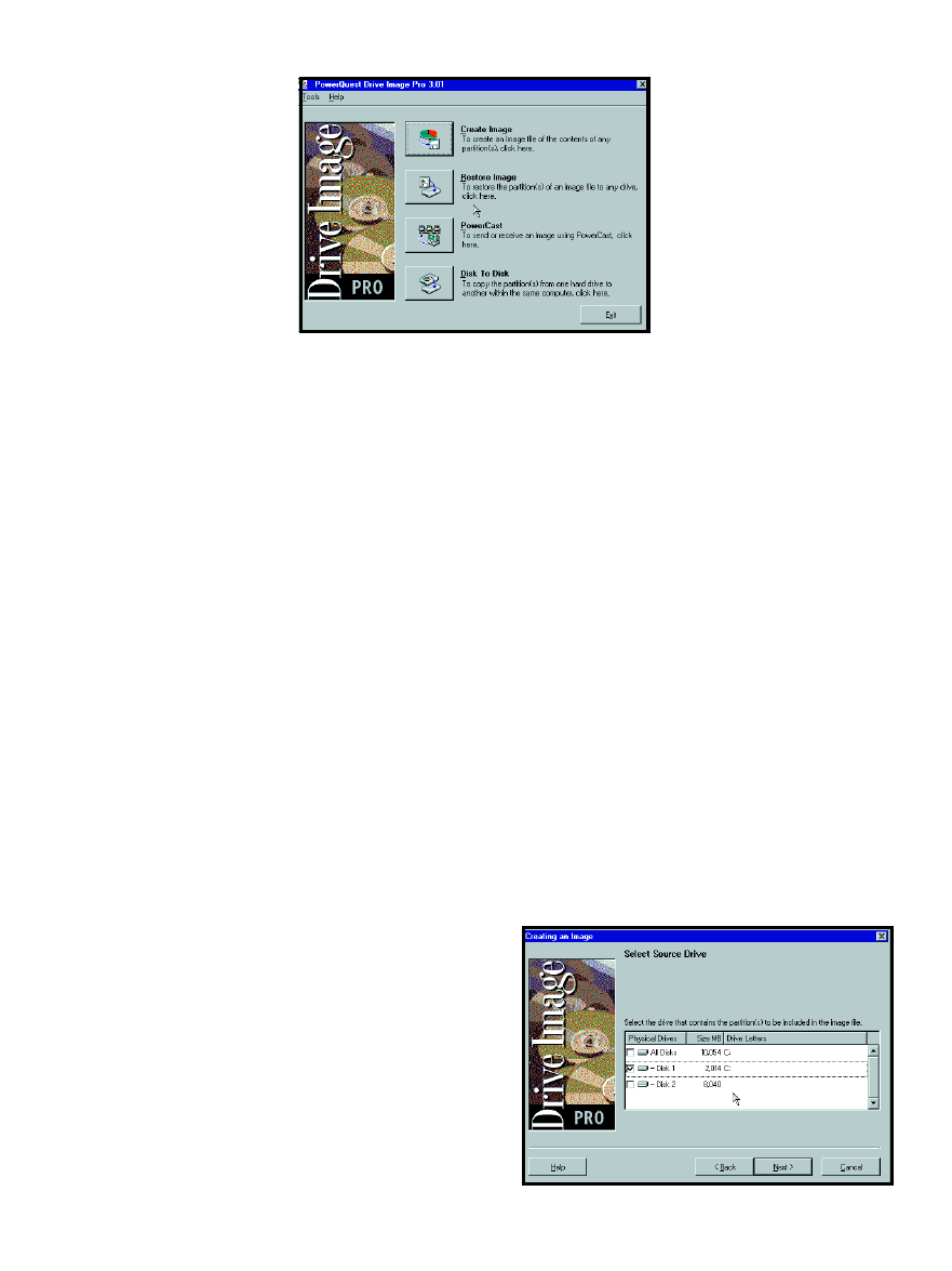
CIRCUIT CELLAR
®
Issue 120 July 2000
49
www.circuitcellar.com
PowerCast boot diskettes
allow you to bring up a
PowerCast Client that is
searching for a PowerCast ses-
sion. Drive Image Pro 3.01 con-
trols in this mode, and although
you can see other PowerCast
Clients from the PowerCast
Server and vice versa, you can’t
reach the network directories.
Network Client boot dis-
kettes are the opposite. You can
access the network directory but
can’t use PowerCast features.
Drive Image Pro 3.01 boot
disks bring up the main Drive
Image Pro interface. Similar to the
Network Client diskettes, you are
allowed to access the network direc-
tory, but you can’t PowerCast. Because
this article is about how PowerCast
works, I chose PowerCast diskettes.
POWERCASTING
Via PowerQuest windows, I was
identified where the Microsoft Net-
work 3.0 Client for MS-DOS files that
I copied from the WinNT Server CD
were located and specify if my NIC
(Network Interface Card) was capable
of Plug-and-Play operation. I used the
SMC9432TX NIC, which lacks jump-
ers and is Plug-and-Play compatible.
If I had used an NIC that required
manual jumper or firmware setup
from diskette, I would have had to
supply an NIC base address and IRQ
settings to the PowerQuest BootDisk
Builder program.
There were many well-known and
popular NICs listed in the BootDisk
Builder selection panel, but my
SMC9432TX wasn’t anywhere to be
CATCHING A BOOT
Now that I have a PQI image to
play with, the next step is to use
PowerQuest BootDisk Builder to pro-
duce PowerCast Server and Client
boot disk sets. Drive Image Pro 3.01
works at the DOS level, and BootDisk
Builder is the PowerQuest way to get
the PowerCast server and clients on a
common network. Booting from DOS
using diskettes also frees any hard disk
on the system, so its contents can be
copied or replaced natively by Drive
Image Pro 3.01 or via PowerCasting.
Interestingly, PowerQuest doesn’t
use Microsoft’s DOS in its PowerCast
diskette build. Instead, Caldera’s
DOS 7.02 is used because it has a
smaller footprint. Using Caldera’s
DOS allows the PowerQuest code and
the supporting DOS files to fit easily
on a set of standard 1.44-MB diskettes.
During the initial installation, I
was asked if I wanted to grab the
Microsoft Network 3.0 Client for
MS-DOS files from a Windows NT
Server 4.0 CD. My choices were as-
sembling a
NDIS file
set manually onto a
pair of boot diskettes,
or allowing Drive Im-
age Pro 3.01 and
BootDisk Builder to do
the work for me, so I
said yes.
BootDisk Builder
creates three available
types of Drive Image
Pro 3.01 boot disk
sets—PowerCast, Net-
work Client, and Drive
Image Pro 3.01.
server to one or more Power-
Cast clients. The neat thing is
that the PQI image is only sent
once, not separately to each
PowerCast Client. Although I
won’t use it here, the Power-
Cast Server has its own BootP
server for broadcasting IP ad-
dresses to the PowerCast Cli-
ents if no DHCP server is
found on the network segment.
To PowerCast, first you
must have or create an image
you want to distribute. I used
Drive Image Pro 3.01 to create
a PQI image of a freshly in-
stalled version of Win98 SE. After
installing Drive Image Pro 3.01 and
producing the initial set of setup
disks, I fired up the new version and
was greeted by the image shown in
Photo 1. When Drive Image Pro 3.01
loaded completely, it presented the
screen in Photo 2. As you can see by
the buttons on the screen, this soft-
ware is tricky. My plan is to make a
PowerQuest PQI image that I can
push around the Florida-room
Ethernet network.
So, I clicked “Create image”,
which brought me to a “Name im-
age” window. I named the image
CCINKIMG.PQI and added a physical
D: drive to the PowerCast Server
machine to store it on. The next
screen allowed me to select which
disk contains the partitions I wish to
place in the PowerQuest PQI image.
Disk 1 contains the new Win98 SE
image I loaded earlier, and Disk 2 is
the clean drive D: I added to hold my
image of the Win98 SE partition on
Disk 1.
After selecting the entire Disk 1
active partition as the source for my
final PQI image (see Photo 3), I didn’t
compress the final image because the
8-GB target hard disk (Disk 2) can
easily handle the PowerQuest PQI
image file. The image creation pro-
cess culminates with the selected
partition data from Disk 1 being
transformed into a single Power-
Quest PQI image file on Disk 2.
When all is said and done, a file
called
CCINKIMG.PQI, which is
408,242 KB, is placed on Disk 2 or
drive D: of the PowerCast server.
Photo 2
—In the previous version, there were only three buttons on this
screen, but the Internet found its way into the world of data recovery.
Photo 3—
I know 8 GB is overkill, but I don’t have anything smaller right now.

CIRCUIT CELLAR
®
Issue 120 July 2000
51
www.circuitcellar.com
Listing 1
—These files are similar to the old
WFW
3.11 networking add-on files with the same names. Param-
eter tweaking is allowed here.
** PROTOCOL.INI
[NETWORK.SETUP]
VERSION=0X3110
NETCARD=MS$SMCPWR2,1,MS$SMCPWR2,1
TRANSPORT=TCPIP,TCPIP
LANA0=MS$SMCPWR2,1,TCPIP
[MS$SMCPWR2]
DRIVERNAME = SMCPWR2$
[PROTMAN]
DRIVERNAME = PROTMAN$
PRIORITY = MS$NDISHLP
[TCPIP]
NBSESSIONS=6
DEFAULTGATEWAY0=
SUBNETMASK0=255 255 0 0
IPADDRESS0=10 10 0 254
DISABLEDHCP=1
DRIVERNAME=TCPIP$
BINDINGS=MS$SMCPWR2
LANABASE=0
** SYSTEM.INI
[NETWORK]
FILESHARING=NO
PRINTSHARING=NO
AUTOLOGON=YES
COMPUTERNAME=inkclient
LANROOT=A:\NET\
USERNAME=CC
WORKGROUP=EDTP
LOGONDOMAIN=EDTP
RECONNECT=NO
DOSPOPHOTKEY=N
LMLOGON=0
PREFERREDREDIR=FULL
AUTOSTART=FULL
MAXCONNECTIONS=8
[NETWORK DRIVERS]
NETCARD=Smcpwr2.dos
TRANSPORT=TCPDRV.DOS,NEMM.DOS
DEVDIR=A:\NET\
LOADRMDRIVERS=YES
[PASSWORD LISTS]
*Shares=A:\NET\Shares.PWL
CC=A:\NET\CC.PWL
found. So, I chose the “Have disk”
button and inserted the SMC Super-
Disk 3.0 that came with my SMC-
9432TX NIC to copy the SMC9432TX
DOS NDIS driver from the SuperDisk
to the Drive Image Pro 3.01 NDIS
driver library. I named the NIC driver
SMCPWR2 to match the DOS name
of the SMC9432TX NDIS driver.
After you load and name an NDIS
driver into the BootDisk Builder NIC
driver window, you can use it again
without having to reload it from other
sources. BootDisk Builder uses the
NDIS driver in conjunction with the
Microsoft Network 3.0 Client for MS-
DOS files to build a diskette that can
be booted. This diskette brings up
Drive Image Pro 3.01 and attaches the
NIC to the network segment.
PowerCasting works over Ethernet
using the TCP/IP services. The Boot-
Disk Builder asks if you’re using a
DHCP server, Drive Image Pro’s
BootP server, or hard-coded IP ad-
dresses to contact the PowerCast
Clients on the network segment. I
chose DHCP, because using a DHCP
server eliminates lots of manual ad-
dress keying and worrying about
what’s what as far as IP addressing is
concerned. If there was no DHCP
server handy on the network segment,
I’d choose Drive Image Pro’s BootP
service to distribute IP addresses.
Because I already have an address-
ing scheme in place (10.10.0.0), I’ll
hard-code a couple IP addresses for the
PowerCast Client (10.10.0.253) and
the PowerCast Server (10.10.0.254).
The process of making a PowerCast
Client and PowerCast Server boot
disk set is nearly identical, unless
you’re making the Client disk set. For
that process, you must specify the
disk number and session name the
Client will use for PowerCasting.
This is where it got interesting. I
initially named the Client session
CCINK CLIENT SESSION. When I
initiated the PowerCast Client, I re-
ceived an error message stating that
the switch “CLIENT” was unknown.
The PowerCast program halted and
returned to an A: prompt.
After a few more hours, I checked
out the Drive Image Pro 3.01 manual
for command line switches. “CLI-
ENT” was not listed as a command
line switch. So, I renamed the session
without it and everything worked.
To keep it simple (and ensure that
the PowerCast would function), I
named the PowerCast session that
transfers the
CCINKIMG.PQI image
“CCINK”. Photo 3 shows that the
future PQI image partition is on Disk 1.
That takes care of the Drive Image
Pro 3.01 startup diskettes. I hooked up
the PowerCast Client and Server
Ethernet cables to some open Ethernet
hub ports and booted the PowerCast
Client and Server boot disk sets.
The PowerCast Client
autoexec.bat file contains a com-
mand line that would automatically
run the PowerCast session upon suc-
cessful connection with a PowerCast
Server with a matching client session
name. The inclusion of the Drive
Image Pro 3.01 command line allows
the remote PowerCast Client to insert

52
Issue 120 July 2000
CIRCUIT CELLAR
®
www.circuitcellar.com
Listing 2
—This file exists for those of you who can’t remember IP addresses.
# Copyright (c) 1994 Microsoft Corp.
# This is a sample LMHOSTS file used by Microsoft TCP/IP
#
# This file contains the mappings of IP addresses to computer
# (NetBIOS) names. Each entry should be kept on an individual line.
# The IP address should be placed in the first column followed by
# the corresponding computername. The address and the LAN Manager
# name should be separated by at least one space.
#
# Note that the utilities will only recognize a finite number of
# mappings. This current limit is 59 for Windows for Workgroups.
#
# Also, comments (like these) may be inserted on individual lines or
# following the machine name denoted by a '#' symbol.
#
# For example:
#
# 149.124.10.4 server1
# main office server
# 182.102.93.122 joe3
# joe's database server
10.10.0.253
inkserver
10.10.0.254
inkclient
itself on the network, find a matching
session name, and initiate the Power-
Cast. I eliminated this line so you can
see the whole operation as it unfolds.
After bringing up the PowerCast
Server, I manually kicked off the
PowerCast Client. At this point, there
was communication and data transfer
between the PowerCast Client and
Server. This was evidenced by the
PowerCast Client’s IP address in the
PowerCast Server’s connected client’s
window. The image file that is being
served is listed in the top left corner
of the PowerCast Server window. In
the lower right, I instructed the server
to wait for one client to attach before
beginning the PowerCast session.
When the PowerCast is complete,
the PowerCast Client’s Disk 1 (C:
drive) has been populated with the
contents of the
CCINKIMG.PQI image
file from the PowerCast Server’s D:
drive. As a final test, I booted the
newly loaded PowerCast Client and
brought to life the Win98 SE image
that now occupies the 1.2-GB client
C: drive.
NETWORK CLIENTS
The PowerCast procedure worked
so well I used the PowerQuest Boot-
Disk Builder to make a set of Net-
work Client boot diskettes, boot them,
and navigate the file resources on my
Ethernet LAN. Using a process similar
to making the PowerCast diskettes, I
input a client IP address (10.10.0.254),
a Workgroup name (EDTP), and a net-
work drive mapping of F: as
\\CCINK\ccink_d. Listing 1 is the

CIRCUIT CELLAR
®
Issue 120 July 2000
53
www.circuitcellar.com
SOURCE
Drive Image Pro
PowerQuest Corp.
(801) 437-8900
Fax: (801) 226-8941
www.powerquest.com
Fred Eady has more than 20 years of
experience as a systems engineer. He
has worked with computers and com-
munication systems large and small,
simple and complex. His forte is em-
bedded-systems design and commu-
nications. Fred may be reached at
fred@edtp.com.
combined set of client
System.INI
and
Protocol.INI files created by the
BootDisk Builder.
A few moments later, I was ping-
ing the Network Client at
10.10.0.254 from a WinNT station on
the EDTP LAN. I selected the “Re-
store image” button, which took me
to an image file selection window.
Drive F: was present and mapped to
\\CCINK\ccink_d. If you remember,
ccink_d is the D: drive that I added to
hold the PowerQuest
CCINKIMG.PQI
file on the PowerCast Server. I then
selected
\\CCINK\ccink_d\
CCINKIMG.PQI and restoration started
in thec cink_d: drive.
Now, I can use this standard UNC
addressing technique to create an im-
age or restore a file from anywhere on
the EDTP LAN.
You may have to tweak some of the
Protocol.INI and System.INI values to
make things work. BootDisk Builder
also places an
LMHOSTS file in the NET
directory of the first boot disk. You
may alter its contents to identify your
Network clients with real names
rather than IP addresses. Listing 2 is an
example of this using the PowerCast
Server and Client machines.
WHAT DOES ALL THIS MEAN?
Basically, you have a way to move
and back up hard disk partitions using
TCP/IP and, in this case, Ethernet. The
backup device no longer has to be in
the same computing device, be that an
embedded PC or a desktop.
Drive Image Pro 3.01 takes the pain
out of making bootable network ca-
pable diskettes. Before BootDisk
Builder, a network programmer had to
assemble the network files required by
MS-DOS networking and the NIC files
by hand. With PowerQuest’s BootDisk
Builder, the work is reduced to careful
thought and a few mouse clicks.
Instead of zipping large amounts of
data, you can use Drive Image Pro 3.01
to produce a good PQI file that can be
stored on nearly any media and trans-
ported using the Internet, an Intranet,
or a simple LAN. Backup and restore
operations can now be done remotely.
Even the software installation can be
automated using the components of
Drive Image Pro 3.01.
Although Drive Image Pro 3.01 is
basically a Windows/DOS application,
it still has a place in the embedded
world. Using DOS as the common
denominator, I can move images and
data at will around my Ethernet LAN.
DOS is not dead. And once again,
everyday DOS has proven that it
doesn’t have to be complicated to be
embedded.
I

54
Issue 120 July 2000
CIRCUIT CELLAR
®
www.circuitcellar.com
Quick and Easy
Motor Control
FEATURE
ARTICLE
t
Before you get your
motor running and
head out on the high-
way, you may want to
listen to what Alan
has to say about the
PIC-SERVO from JR
Kerr Engineering. If
you need to control a
DC motor with encoder
feedback, this chip
will fit the bill nicely.
here are many
methods for con-
trolling motors. You
can use stepper motors,
DC motors that use PWM and encod-
ers for feedback, or a complete preci-
sion motion control system that uses
an LM628 motion-control chip.
These systems require a lot of
work building and programming mi-
croprocessors to get the motor started.
This article will show you how to
achieve the first move in an hour, for
only about $40!
NEW PRODUCT
Recently, JR Kerr introduced a new
product that is helpful for controlling
a DC motor with encoder feedback.
The PIC-SERVO is a pair of PIC mi-
crocontroller chips designed to imple-
ment a PID servo-control system.
The system is implemented as a
two-chip set. One chip is used as a 16-
bit quadrature encoder counter. The
other is used to implement the PID
control algorithms and communicate
through an asynchronous serial port
to a host computer or microprocessor.
The set is available for $35 through
several distributors. You only need to
add a motor driver.
The JR Kerr web site provides ex-
cellent descriptions of the pinouts,
theory of operation, example imple-
mentation, and sample code, so I
won’t expound on those. Follow the
schematic in the documentation,
hook it up to your serial port, and
let’s get going (see Figure 1).
MOTOR CONNECTIONS
First, you need to hook up the
motor correctly. Attach the encoder
inputs to the PIC-ENC chip, and at-
tach the motor power leads to the
motor driver. If you have more than
one PIC-SERVO chipset, set the ad-
dresses of each chipset using the in-
structions at the JR Kerr site.
Next, use the PIC-SERVO PWM
mode to confirm the motor is hooked
up correctly. Enable the PWM mode
with the
LOAD_TRAJECTORY com-
mand, and set a PWM value to about
64 to get the motor moving.
You can determine if the position
values are counting up or down by
using the
READ_STATUS command.
They should be counting up. If they
are counting down, reverse either the
motor’s power connections or swap
the A and B encoder wires. Then,
using the
LOAD_TRAJECTORY com-
mand, reverse the direction of the
motor and verify that the encoder
counts down.
At this point, the motor and en-
coder are wired properly. However, if
you want the positive direction of
motion to be the other way, swap the
motor power and encoder connections.
Go through this exercise for each
motor/encoder/PIC-SERVO unit. After
you have your motors correctly wired
and tested, let’s get to the PID part.
SAFETY
The motor-control values depend
on your robot’s configuration. Com-
pletely assemble the robot before
tuning the motion controls. If you add
equipment later, you will probably
have to tune the controls again.
You are going to instigate strange
motions for the motors and mechan-
ics, so be prepared with an emergency
stop button. Something can catch in a
gear train easily, or the mechanics
may fly apart during tuning. You can
hook up a switch in series with the
motor DC power supply to stop the
motors when things get out of hand.
Alan Kilian
Implementing a PIC-SERVO Controller
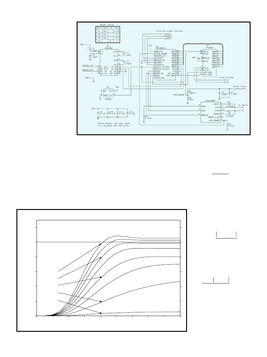
CIRCUIT CELLAR
®
Issue 120 July 2000
55
www.circuitcellar.com
PROPORTIONAL TERM
Here are some abbrevia-
tions that I’ll use for the
article. The proportional
gain is called Kp. The de-
rivative gain is Kd, and the
integral gain is Ki. The
desired position, velocity,
and acceleration are P, V,
and A. The position error,
where you want to be minus
where you are, is Ep. And,
Ev is the velocity error, how
fast you want to go minus
how fast you are going.
Let’s review the PID
coefficients. Prop your robot
off the ground so that the
wheels can turn. Send two
packets to the PIC-SERVO
to get things set up. Use the
LOAD_TRAJECTORY com-
mand to set P to zero, V and
A to a large value like 0x1FFFFFFF, and
enable the servo loop. Then, use the
SET_GAIN command to set the posi-
tion-error limit to 0x3FFF, and the Kp,
Kd, and Ki terms to zero.
Kp indicates how hard the motor
should work to remain in its current
position. Set Kp to 1 and enable the
servo loop; the motor will stay where
it was when you enabled the servo.
If you move the motor shaft by
hand, the motor driver will try mov-
ing the motor back to where it
started. It can’t achieve starting loca-
tion, but you should be able to see a
voltage across the motor with a volt-
meter, or a ’scope. If you turn the
motor in the other direction, you
should see the motor-direction bit
change. If these things happen, the
controller is trying to servo the motor
back to its desired location. The value
of the PWM signal is:
PWM =
Kp × Ep
256
where PWM = 0 is fully off, and PWM
= 255 is fully on. You can see this if
you have a 400-count-per-revolution
encoder. With 1 Kp, you need
to turn the motor 80 revolu-
tions to get the PWM signal
half-way on.
PWM = 1 ×
400 × 80
256
= 125
If you choose a Kp of 160, the
PWM signal can turn fully on
in one revolution:
160 × 400 × 1
256
= 250
Because you only set the Kp
term to 1, it’s like you have a
weak spring trying to move
the motor back to the start-
ing location. The farther you
move it from its set point,
the harder the motor turns
on. You need to turn it far to
Figure 1—
This is a schematic for the minimal PID control system using the PIC-SERVO.
0
200
400
600
800
1000
1200
0
0.02
0.04
0.06
0.08
0.1
0.12
0.14
0.16
0.18
Encoder counts
Seconds
Kp = 100 through 800, Ki = 0, Kd = 0
Kp = 100
Kp = 200
Kp = 400
Kp = 600
Kp = 800
Desired position
Figure 2—
This shows the motion trajectories when using only Kp.
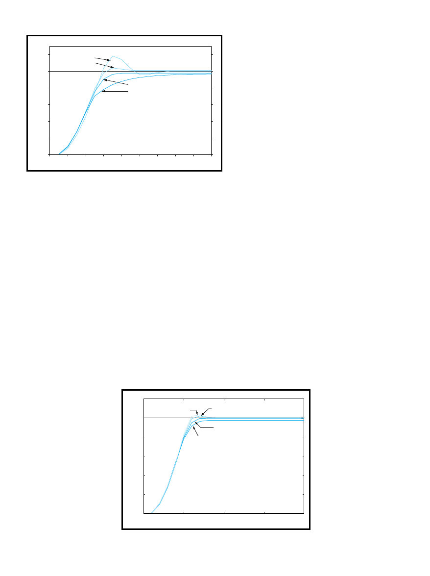
56
Issue 120 July 2000
CIRCUIT CELLAR
®
www.circuitcellar.com
lating around the desired set point,
never stopping at the correct point.
The servo loop works perfectly. The
problem is that you didn’t program
the motor to stop at the set point, you
programmed it to head towards the
set point if it’s not there.
If you increase Kd, you’re telling
the servo to follow a desired velocity
in addition to a desired position. The
PIC-SERVO will internally generate
both a desired position and a desired
velocity 2000 times per second during
the move. It compares these values to
the actual position and velocity and
generate two error signals, Ep and Ev.
Now, I’ll explain how Ev and Kd
make it speed up or slow down. The
PIC-SERVO wants the motor to stop
when it is at the end of a move, so the
desired velocity is zero, but the actual
velocity is the motor’s speed as it
passes the set point. Because the mo-
tor is going too fast, the control loop
reduces the PWM duty cycle to slow
the motor as it nears the end of its
move. The larger the Kd value, the
more the system tries to make the
motor follow the desired velocity and
stop at the end of the move.
If Kd is too great, the slightest
motor motion causes the motor to
turn on fully in the opposite direction,
which makes the motor move in that
direction, which, in turn, makes the
controller turn the motor on in the
other direction. You can experiment
with this value by setting Kp to zero,
Kd to 100, and giving the motor a fast,
sharp tap that causes a significant
velocity error and determines if Kd is
too great.
You should hear a quiet buzz, but
you might get a wildly oscillating
motor that tries to break your gear
train, so be ready with the off switch.
FIRST STEPS
Try to make a 1000-count step.
First, set the velocity and acceleration
values to high values (100,000 for
both). Set Kd to the highest value that
didn’t cause things to break, and set
Kp to 100. Then, set the PIC-SERVO
to servo mode by sending the
LOAD_TRAJECTORY command fol-
lowed by the position, velocity, and
acceleration values.
Issue a
START_MOTION command
and watch what happens. The motor
moved, but probably not the entire
1000 counts. It should
move in the correct direc-
tion at least. Move the
motor by hand, watching
the encoder values and the
status until it reaches
1000 counts. After the
status confirms it’s com-
plete, begin increasing the
Kp value, making one-
rotation moves until the
motor makes a move of
almost 1000 counts.
If the motor moves
more than 1000 counts,
turns around, goes back
past the set point, reverses
again, and oscillates for-
ever, there’s too much Kp.
get more motor torque. Increasing Kp
means the controller works harder to
hold the motor at the original position.
Now, try setting Kp to higher val-
ues. A value of 2000 will probably be
like a strong spring. If you move the
encoder 32 encoder counts (29°), the
motor will turn on fully, trying to get
the encoder back to zero.
The motor will vibrate back and
forth across the set point like a spring.
In fact, you probably should sneak up
on the larger values. Jumping to a
large value might cause your motor to
vibrate quickly and overheat.
Testing with only Kp gives poor
performance. First, Kp is set too low,
and the motor doesn’t get close to the
desired position. As you increase Kp,
you get closer to the target location;
then it begins to overshoot the target
and backs up. Even greater Kp values
make the motor overshoot
and then oscillate around
the desired stopping point.
Figure 2 shows the result
of moving a 1000-encoder
count using Kp = 100
through Kp = 800.
THE DERIVATIVE TERM
The Kd term controls the
desired velocity, like the Kp
term controls the desired
position. The “d” stands for
derivative, and the deriva-
tive of position is velocity,
so let’s call it velocity.
You’ve probably in-
creased Kp to get the motor
running, and now it’s oscil-
0
200
400
600
800
1000
1200
0
0.02
0.04
0.06
0.08
0.1
0.12
0.14
0.16
0.18
Encoder counts
Seconds
Kp = 320, Ki = 0, various Kd
Kd = 1000
Kd = 5000
Kd = 8000
Kd = 17000
Desired position
Figure 3—
These
are the motion
trajectories when
using Kp and Kd.
0
200
400
600
800
1000
1200
0
0.05
0.1
0.15
0.2
Encoder counts
Seconds
Kp = 320
Kp = 400
Kp = 500
Kp = 590
Desired position
Kd = 8000
Figure 4—
These motion trajectories are the results you get from using a large Kd value
and increasing Kp values.

CIRCUIT CELLAR
®
Issue 120 July 2000
57
www.circuitcellar.com
TEST DRIVE
Because I planned to test
drive the controller, I
wanted a simple way to see
what a move looks like. I
built a motion control sys-
tem to drive an Etch-a-
Sketch (check out www
.etch-a-sketch.com/).
Each knob was replaced
with a nylon gear and two
motors and 96 line encod-
ers were mounted to a base
plate. Because each line on
a quadrature encoder pro-
duces four counts at the
encoder counter, this gave
me 384 counts per revolution at the
motor, and with a 122:24 gear ratio, a
total of:
384 × 122
24
= 1950
counts per revolution at the knob.
Using the PIC-SERVO, I drove the
horizontal knob at a constant veloc-
ity, and commanded the vertical mo-
tor to do a step motion. The high gear
ratio makes it difficult to see the
ringing by looking at the screen.
Figure 2 shows that I need 600 Kp
before I get close to the desired set
point. Kp values greater than 600
overshoot the desired set point.
Figure 3 shows what happens when
I increase Kd from 1000 to 8000. As
Kd increases, performance gets better
until it reaches 8000, then the perfor-
mance worsens and never
reaches the set point.
Figure 4 shows what hap-
pens when I increase Kp
using 8000 Kd. Again, perfor-
mance increases to a point,
and then gets worse.
WHAT’S THE I TERM?
If you’re going to control a
simple robot that won’t try
to stop on a hill, or need to
be precise in its location,
you don’t need an I term.
To demonstrate the I
term’s value, I added a stick
and ball of clay to the Etch-a-
Sketch. If I try to position the motor
so the stick is horizontal, the clay
will force the motor off position. This
simulates a robot stopping on a hill.
The
READ_STATUS command moved
the position and velocity and plotted
the results using a graphing program.
With an upward move, the motor
stops too soon and never reaches the
desired location (see Figure 3). If you
add more Kp to get it to stop at the
-600
-500
-400
-300
-200
-100
0
100
0
0.1
0.2
0.3
0.4
0.5
0.6
Encoder counts
Seconds
Integral gain example
Ki = 0
Ki = 100
Kp = 300, Kd = 8000
Figure 5
—Notice the motion trajectories that result when using different Ki values.

CIRCUIT CELLAR
®
Issue 120 July 2000
59
www.circuitcellar.com
SOFTWARE
The parts list and software is avail-
able on the Circuit Cellar web site.
SOURCES
PIC-SERVO
J R Kerr Automation Engineering
www.jrkerr.com
Distributors
Jameco
(800) 831-4242
(800) 237-6948 Fax
www.jameco.com
HdB Electronics
(650) 368-1388
(800) 2 TRY HDB
Fax: (650) 368-1347
www.hdbelectronics.com
correct location, you will overshoot
the end point and ring. The motor
won’t stop at the set point. If you look
at what’s happening, you’ll under-
stand why.
Imagine that the motor did stop at
the set point. What would happen?
The position and velocity errors
would be zero, so Kp × Ep + Kd × Ed =
PWM = 0. The motor is turned off and
it falls backwards due to the weight.
Then Ep, Ev, and PWM increase, get-
ting closer to the endpoint again.
If you could use the constant posi-
tion error to increase the PWM, you
could pinpoint the set point. If you
could leave that PWM value on when
you get to the set point, you would be
able to stop at the set point even if
there is a force trying to move it away
from the set point.
That’s what the I term does. It
allows the error value to add up over
time, and makes the motor move
slowly to the final set point. Be care-
ful because too much Ki or integral
limit can make things unstable
quickly. Figure 5 shows what happens
with a 0 and 100 Ki.
MOVE LENGTHS
Figure 6 shows the performance
when you try to do different lengths
of moves. Performance is successful
to a move length of 2000 encoder
counts, then it overshoots. This
means that you may need different
parameters depending on the move
length. There is no penalty for looking
at the length, and then setting the
coefficients for that move differently
from the other lengths.
GET MOVING
Getting a PID control loop to per-
form is complex. By trying different
values, you might get the desired
performance. Or, you may reach the
goal by starting with one parameter,
changing it until you get good perfor-
mance, and then working on the oth-
ers systematically.
You’ll learn a lot by taking the
system for a spin, and you’ll get a
great motion control system, too.
I
Figure 6—
These
are the motion
trajectories for
various move
lengths.
-500
0
500
1000
1500
2000
2500
3000
3500
4000
0
0.05
0.1
0.15
0.2
-500
0
500
1000
1500
2000
2500
3000
3500
4000
Encoder counts
Seconds
Alan Kilian is a lead visualization
programmer at the University of
Minnesota’s Computational Biology
Centers. He’s worked as a program-
mer for 17 years at Cray Research
Inc. and CyberOptics Inc. and is a
founding member of the Twin Cities
Robotics club (www.tcrobots.org). You
may reach him at kilian@pobox.com.

60
Issue 120 July 2000
CIRCUIT CELLAR
®
www.circuitcellar.com
Two Ports in
a PIC
EMBEDDED
LIVING
Mike Baptiste
Getting your thermo-
stat to communicate
with your HCS-II may
be easier than you
think according to
Mike. He used a
PIC16F876 to cre-
ate the Stat-Link and
now there’s no lack
of communication
between his thermo-
stat and his HCS-II.
ast time, we
covered the basics
of HVAC control and
how to integrate it with
a home automation system. One of
the central devices for automated
HVAC control is a communicating
thermostat. Most communicating
thermostats use serial ports to
communicate with home automation
controllers. They come with either
RS-232 or RS-485 ports. Because the
HCS-II has an RS-485 port, connecting
a communicating thermostat should
be a snap—“should” being the
operative word here.
When I decided to add support for
communicating thermostats to the
HCS-II, I wanted to support thermo-
stats from multiple vendors. Home
automation enthusiasts are finicky
when it comes to their preferences. If
you choose one type of device, you’ll
quickly find a large (and vocal) group
of users who want another.
There is no standard when it
comes to communicating thermo-
stats. Each vendor has developed its
own control protocol. Add HCS-II’s
protocol to the mix, and you are
faced with a difficult situation. One
advantage, though, is that most of
the serial thermostats run at
9600 bps, which is the same speed as
the HCS-II network.
One way of adding support is to do
it all in the XPRESS firmware and
have the thermostats connected di-
rectly to the HCS-II RS-485 network.
This keeps costs low, but it can bloat
the firmware because of the multiple
protocols. It also requires changes to
the basic serial routines because the
thermostats don’t use checksums,
have different addressing schemes,
and may not appreciate seeing all the
HCS-II network traffic.
Considering the difficulties in-
volved in adding the support directly
to the HCS-II firmware, I decided to
develop a network protocol interface.
One side would receive and respond
to regular HCS-II commands, and the
other would handle the thermostat
communication. Adding support for
multiple vendors is possible because
you can use a look-up table to get the
proper command based on the config-
ured type of thermostat. Sounds easy!
Yes, well, we all know better.
STAT-LINK
Because this device will link the
thermostats to the HCS-II, I began
calling it the Stat-Link. Communicat-
ing thermostats generally accept com-
mands to control the temperature set
points and HVAC system. They also
report system status and temperature
readings back to the controller. Thus,
the Stat-Link has to be able to send
commands to the thermostats and
also query them to get status and
temperature data, which is relayed
back to the HCS-II.
The HCS-II retrieves data from
network nodes by constantly querying
each module for data. Because Stat-
Link will have data for all the thermo-
stats in use (up to 32), the HCS-II will
get all the thermostat’s data in a
single query. However, this presents
an interesting problem. Stat-Link has
to constantly query the thermostats
for data and also return that data
when the HCS-II asks for it. This
means all the thermostat data has to
be buffered in memory because there
is not enough time to query all the
thermostats in real time.
To ensure that the HCS-II has the
most recent thermostat data, Stat-
Link must constantly query each
A Communication
Thermostat
l

CIRCUIT CELLAR
®
Issue 120 July 2000
61
www.circuitcellar.com
thermostat. If new control commands
arrive from the HCS-II, those must be
sent, too. Because the HCS-II asks for
data whenever it wants to, Stat-Link
must be able to respond to HCS-II
queries, regardless of what it is doing
on the thermostat side. This arrange-
ment will require some type of CPU
sharing or multitasking arrangement.
Without this, you risk responding to
an HCS-II query too late if you are
busy querying a thermostat (which
requires sending a query command
and processing the reply).
IT GETS WORSE
When it comes to small embedded
devices, I tend to use Microchip PICs.
I’m familiar with them, I have lots of
development tools, and I like the
price. However, the one thing I wish
Microchip would develop is a 16C6x
PIC that has two hardware UARTs. I
desperately needed an extra one for
this project.
So far, I needed a PIC with a hard-
ware UART, lots of RAM for the nu-
merous network and data buffers, and
some type of flash memory to store
configuration information. Microchip
recently started shipping their new
16F87x series of chips. These are basi-
cally 16C7x cores with flash RAM
and program memory.
By using this chip, I gained the
ability to program the devices on-
board via the In-Circuit Serial Pro-
gramming (ICSP) port. In the future, it
might allow users to upgrade the
firmware of their Stat-Link through
their PC using a simple programming
interface connected to a PC serial
port. Because of the amount of RAM
required, I chose the 16F876, which
has 368 bytes of RAM, 256 bytes of
flash RAM, and 8 KB of program
memory.
TWO IS WORSE THAN ONE
Before I started coding, I realized I
had a tough design challenge to over-
come. I only had one hardware UART,
so the other serial port would have to
be bit banged. The thermostat serial
port is the simpler port because the
thermostats will only transmit when
queried. However, the HCS-II port has
to be ready for HCS-II traffic at all
times because the HCS-II constantly
queries the modules for data.
HCS-II network traffic is unpre-
dictable and thus requires the hard-
ware UART so data can be received in
the background with minimal CPU
attention. This means, the thermostat
serial port is managed in software.
The hard part is handling incoming
HCS-II data when a character is being
bit-banged in or out of the thermostat
serial port. Bit-banged serial ports
require precise timing to ensure that
the proper transfer rate is reached.
This generally requires the CPU to
wait in a loop during each bit. So, you
lose the CPU for other processing—
1.04 ms, the time required to transmit
or receive a single byte at 9600 bps.
The hardware UART has a two-
byte FIFO receive buffer. At first, I
figured this would solve all of my
#INT_RDA
// Interrupt when UART RCV Buffer is Full
void hcs_serial_in() {
// Let grab the character and raise an error if necessary
if (hcs_rx_buff == 0) {
// Ensure we processed the last byte
hcs_rx_buff = RCREG;
} else {
HCS_ERR_LED = LED_ON;
}
}
#INT_TBE
// Interrupt when Tx buffer is empty
void hcs_serial_out() {
if (hcs_tx_off) {
// Enable the one shot since transmission is done
set_timer1(0xFC69); // Set Timer 1 for approx 1040us
enable_interrupts(INT_TIMER1);
hcs_tx_off = FALSE;
} else {
if (hcs_txbuff_ptr > HCS_TXBUFF_END) {
// We blew out the buffer!
HCS_ERR_LED = LED_ON;
hcs_tx_off = TRUE;
} else {
// Load next character into the UART Tx buffer
old_IRP = IRP;
// Save for later!
IRP = 0;
// Select Bank 1
TXREG = *(hcs_txbuff_ptr);
IRP = old_IRP;
if (*hcs_txbuff_ptr == 0x0D) {
// Its the end of the packet, but the data is buffered so we
// can't turn off the RS-485 enable here or we lose the last few
// chars. Thus we use Timer 1 to delay the shutdown of the
// Enable lines
hcs_tx_off = TRUE; // Signals to start timer next time through
} else {
hcs_txbuff_ptr++;
}
}
}
}
#INT_TIMER1
void hcs_serial_out_end() {
// The buffer should be empty so turn off the UART and RS-485 Enable
TXEN = 0;
// Turn off transmitter
HCS_ENABLE = 0;
// Turn off RS-485 enable
HCS_TX_LED = LED_OFF;// Turn off Tx LED
CREN = 1;
// Turn Rx back on (avoids echo processing)
hcs_txbuff_ptr = HCS_TXBUFF_START;
// Signals the buffer is free
disable_interrupts(INT_TIMER1);
}
Listing 1
—The HCS-II serial port interrupt routines use the hardware UART in the PIC. Notice that a timer
is still required as a result of the lack of an interrupt when the transmit shift register is empty.

62
Issue 120 July 2000
CIRCUIT CELLAR
®
www.circuitcellar.com
problems. A two-byte FIFO buffer,
plus the incoming shift register
would allow almost three bytes to be
received before an overflow occurred.
Even though the non-UART serial
port requires complete attention
during a byte transmission or recep-
tion, I could empty the HCS-II re-
ceive buffer (or load the next byte
into the transmit buffer) between
each thermostat byte.
However, I realized there would be
a lot of processing involved for the
thermostat packets, translating com-
mands, storing data in buffers, main-
taining ring buffers, and so forth.
Besides that, the HCS-II wants to see
a reply within 50 ms of any query. If
an HCS-II query arrived during the
start of a thermostat query, it might
be 50 ms or more before you can pro-
cess the query as a result of serial port
processing and delay loops. This de-
pends on the number of bytes sent
and received on the thermostat side.
It quickly became clear that this
approach would waste too much CPU
time in delay loops while data was
bit-banged in or out of the serial port.
I had to come up with another strat-
egy to make better use of the CPU.
A RABBIT TRIGGERS AN IDEA
Like many of you, I was intrigued
by the new Rabbit Semiconductor
CPU that has saturated advertising
lately. I bought one of the develop-
ment kits, and ideas for potential
projects started flowing. But, that’s
another article or two.
Nevertheless, while I was reading
up on what the Rabbit could do, I
came across a section in the manual
referring to Dynamic C’s Cooperative
Multitasking. Simply put, cooperative
multitasking allows other tasks to
run while the current task sits in a
delay loop. Maybe I could do some-
thing similar with the Stat-Link.
Could a PIC handle it?
Of all the projects I’ve worked on,
this has been the most challenging. I
spent weeks just thinking about ways
I could manage both serial ports, pre-
vent any data loss, and still perform
the functional processing needed. I got
so discouraged, at one point I consid-
ered using an external UART chip
Listing 2—
The thermostat serial routines are more involved because they implement a UART in software.
They function in the background by using a combination of timers and interrupts.
#INT_EXT
void tstat_serialrx_start() {
// Set Timer2 to 1 1/2 bit time minus a few ticks
// for bit sampling and interrupt handling
// 104us per bit @ 9600 bps.
// We are running at 3.6864 MHz which is 1.085us per timer tick
// This results in approximately 96 timer ticks per bit
// Interrupt Service routine takes about 8 ticks.
// So 144, minus 8 ticks means set Timer 2's match register to 136
TMR2 = 0x00;
// Start of from 0x00 1st time through
PR2 = 0x88;
// Set it to 136 ticks for match
tstat_bitctr = 8;
STAT_RX_LED = LED_ON;
disable_interrupts(INT_EXT);
// Disable until next start bit
enable_interrupts(INT_TIMER2);
}
#INT_TIMER2
void tstat_serial_rx() {
int
sample_ctr;
// We either shift in a bit or shutdown during the stop bit
if (tstat_bitctr == 0) {
// We are at the stop bit, lets shutdown
disable_interrupts(INT_TIMER2);
enable_interrupts(INT_EXT);
// So we get the next start bit
old_IRP = IRP;
IRP = 1;
// Select Bank 2/3
IRP = old_IRP;
if ((*tstat_buff_ptr == 0x0D) || (*tstat_buff_ptr == 0x0A)) {
// End of packet!
tstat_rxdata_ready = TRUE;
// Indicate the packet is here
STAT_RX_LED = LED_OFF;
// Turn LED off
}
tstat_buff_ptr++;
// Point to next char in buffer
} else {
// Lets sample 3 times for accuracy
sample_ctr = STAT_RX;
delay_us(1);
if (STAT_RX) { sample_ctr++; }
delay_us(1);
if (STAT_RX) { sample_ctr++; }
delay_us(1);
// If sample_ctr = 0|1 -> 0 2|3 -> 1
old_IRP = IRP;
IRP = 1;
// Bank switch
shift_right(tstat_buff_ptr, 1, bit_test(sample_ctr,1));
IRP = old_IRP;
// Restore previous bank selection
}
}
#INT_RTCC
void tstat_serial_tx() {
set_rtcc(0x7C);
// Set timer up here to maintain exact
timing
if (tstat_buff_empty == TRUE) {
// Must be a new character and/or packet
// Lets enable the drivers and bang out the start bit
STAT_TX = 0;
// Start bit
STAT_ENABLE = 1;
// Turn on 485 drivers
STAT_TX_LED = LED_ON;
// Turn LED on
(continued)

CIRCUIT CELLAR
®
Issue 120 July 2000
63
www.circuitcellar.com
Listing 2
—(continued)
enable_interrupts(INT_RTCC);
tstat_buff_empty = FALSE;
tstat_bitctr = 8;
} else {
if (tstat_bitctr == 0) {
// End of stop bit - disable bus
STAT_ENABLE = 0;
tstat_buff_empty = TRUE;
// Flag that we are done with
// current char
old_IRP = IRP;
IRP = 1;
// Select Bank 2/3
if (*tstat_buff_ptr == 0x0D) {
// CR means end of packet - disable interrupts
disable_interrupts(INT_RTCC);
tstat_buff_ptr = TSTAT_BUFF_START; // Reset buffer pointer
STAT_TX_LED = LED_OFF;
}
IRP = old_IRP;
} else {
tstat_bitctr--;
// Decrement bit counter
if (tstat_bitctr == 0) {
STAT_TX = 1;
// Start of stop bit
} else {
// Data bits. Lets send it
old_IRP = IRP;
IRP = 1;
// Select Bank 2/3
STAT_TX = shift_right(tstat_buff_ptr, 1, 0);
IRP = old_IRP;
}
}
}
}
interfaced with the unused synchro-
nous serial port in the PIC.
Yet, going that route spells defeat. I
knew I could pull this off with just
the single PIC. But how?
NOT QUITE MULTITASKING
I wasn’t at the point of trying to
develop a tiny RTOS for the PIC.
There had to be a way to handle both
serial ports in the background.
Bit banging a serial port is straight-
forward. You simply shift the bits in
or out and wait for a preset delay until
the next bit timeslot. You spend
about 90% of the time in the delay
loop, which is a waste of CPU cycles.
I needed to time the bits in hard-
ware. PICs may lack some things, but
timers are not one of them. The
16F876 has three timers, each with a
slightly different behavior. Luckily,
each timer fit into the task at hand.
Instead of timing the bit delay in a
loop, I used a hardware timer. When
the timer expired, I could generate an
interrupt to shift the next bit in or
out. The critical requirement was
making sure the processor could be
interrupted without delay to ensure
that the bit timing stayed within
tolerances.
The only other critical task was to
make certain that the HCS-II UART
buffer did not overflow or that the
bytes were not loaded in during a
transmit without a decent delay span
between them. If the CPU is in the
process of writing or reading a UART
buffer, this delays a thermostat serial
interrupt. However, as long as the
HCS-II serial port interrupt routines
are kept as short as possible, the de-
lays should not cause a problem.
One key detail is that most serial
devices read the bit state of incoming
data as close to the middle of the bit
timeslot as possible. This gives you a
little wiggle room. When sending a
bit, if you shift the next bit a few
microseconds late, it won’t matter.
The same goes for receiving bits. You

64
Issue 120 July 2000
CIRCUIT CELLAR
®
www.circuitcellar.com
shoot for the middle of the bit, but at
9600 bps, you have 52
µ
s until the
next bit timeslot. So, if an HCS-II
interrupt routine started right before
your preferred sample slot, as long as
it only took a few microseconds, it
should still be safe to sample the bit
slightly past the middle.
SERIAL PORTS VIA INTERRUPTS
Most of the data moved in the Stat-
Link would be buffered, so it was
feasible to handle all serial I/O via
interrupt routines that accessed buff-
ers. This allows for packet processing
between serial bits, not just bytes.
Listing 1 contains the interrupt
routines used to communicate with
the HCS-II via the hardware UART.
In many of my other PIC-based HCS-
II modules, I handle the packet ad-
dress and checksum processing in the
serial receive routine. However, the
Stat-Link HCS-II interrupt routines
have to be as short as possible to
minimize any delay in the thermostat
serial bit banging.
To reduce the size of the receive
routine, I simply buffer the incoming
character and let the main routine
process it. This means the main loop
must check this buffer every millisec-
ond. The transmit routine is straight-
forward except for one trick.
The data to be transmitted is
stored in a buffer. The main code puts
the first character in the UART buffer
and then lets the interrupt handle the
rest. After the data is sent, the RS-485
enable line must be turned off and the
Rx UART turned back on to prevent
data echo. This was not as simple as
it seems.
The 16F876 has an interrupt,
INT_TBE, which is triggered when
the UART transmit register is empty.
However, when the buffer is empty
and this interrupt triggers again, there
is still one byte in the transmit shift
register. Turning off the enable line
right away would prevent the last
character from being sent properly.
To handle this, I used another PIC
timer. When the INT_TBE interrupt
triggers after the last byte has been
loaded, you need to delay turning off
the enable line for another 1040
µ
s.
This will allow the last byte to be
shifted out of the transmit buffer. I
preset Timer 1 and waited for it to
expire after 1040
µ
s. It is actually
slightly less to allow for interrupt
handling time and so forth.
When Timer 1 expires,
hcs_serial_out_end turns off the
RS-485 enable line and re-enables the
Rx UART. The 16F876 has a flag,
TRMT, which indicates when the
UART Transmit Shift Register is
empty. Yet, it cannot generate an
interrupt, and I did not want to lock
up the CPU polling the flag until it
flipped. Adding an interrupt for this
flag in future chipversions would
make the PIC hardware UARTs easier
to use in RS-485 networks.
BANG, BANG, BANG
The fun begins when trying to bit
bang the thermostat serial port via
interrupt routines. First, because the
thermostats are half-duplex, we can
use the same packet buffer for trans-
mits and receives. This makes it
easier to write the routines and also
saves precious RAM space.
Listing 2 contains the routines
used for communicating with the
thermostats. Sending data to the ther-
mostats is clear-cut. The first time
through, the interrupt routine turns
on the RS-485 enable line, sets Timer
0 for 1 bit (104-
µ
s Interrupt Latency/
Handling Time), enables the Timer 0
interrupt, and returns.
Now, you may be thinking, “Hold
on here, why are you enabling the
Timer 0 interrupt inside the Timer 0
interrupt routine?” The reasoning
behind this is to make the main code
simpler and maintain the bit timing.
The transmit routine is a state ma-
chine with four states—Start bit, Data
bit, Stop bit, and After Stop bit. By
including the interrupt setup in the
Start bit state, my main code is
simple. I load the data in the thermo-
stat serial buffer and call the transmit
interrupt routine directly. After that,
the main code is free to do other tasks.
Every time Timer 0 overflows, you
shift out the next bit. After the Stop
bit is sent, the RS-485 enable line is
turned off on the next interrupt, and
the state machine is reset in prepara-
tion for the next packet.

CIRCUIT CELLAR
®
Issue 120 July 2000
65
www.circuitcellar.com
b
Mike Baptiste runs his own company,
Creative Control Concepts, which
designs and sells home automation
equipment, including the HCS-II. You
may reach him at baptiste@cc-
concepts.com.
Receiving data requires two rou-
tines and two interrupts. To avoid
polling the receive pin for incoming
data, the INT_EXT interrupt is used.
This interrupt is triggered by a
change of state on the thermostat
serial receive pin (
RB0/INT). When a
start bit is received, the INT_EXT
service routine initializes the receive
interrupt timer.
Timer 2 is used for data reception.
It is slightly different than the others
because it is a count up and match
timer. When the timer matches the
match register, it generates an inter-
rupt, automatically resets to 0x00,
and continues to count. This is ideal
because it ensures that our bit timing
will remain precise, regardless of
how long the service routine takes.
When Timer 2 causes an interrupt,
the serial receive service routine
simply receives the next bit directly
into the packet buffer. If the entire
byte has already been received and
the stop bit is in progress, you just
shutdown and wait for the next start
bit. If the entire packet has been
RESOURCE
Microchip 18F87x Datasheet
www.microchip.com/Download/
Lit/PICmicro/16F87X/30292b.pdf
XPRESS code. I’ll also touch on some
other applications for the infamous
Stat-Link.
IL
received, a flag is raised, so the main
code knows new data is ready.
LOOKING BACK
In retrospect, the code required to
manage two serial ports with only
one UART turned out to be less com-
plicated than I had anticipated. How-
ever, it took a long time to finalize
the concept and put it into code. It
wasn’t intuitively obvious, to me
anyway. The beauty of this configu-
ration is in the little CPU time spent
on serial I/O, even though one port is
bit-banged. This leaves extra cycles
for the main program code.
The serial code is portable, and
I’ve already got big plans for it in
other devices (some are already de-
signed but could use the extra
cycles). Hopefully you’ve got a few of
your own.
I never expected serial I/O to take
up a whole article, but it did! Next
time, I’ll finally dive into the hard-
ware and code required to manage
the thermostats, as well as how to
integrate the thermostats into your
SOURCES
PIC 16F876
Microchip
(480) 786-7200
Fax: (480) 899-9210
www.microchip.com
Development Kit
Rabbit Semiconductor
(530) 757-8400
Fax: (530) 757-8402
www.rabbitsemiconductor.com
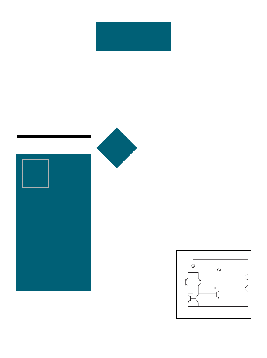
66
Issue 120 July 2000
CIRCUIT CELLAR
®
www.circuitcellar.com
Part
4
4
Op-Amp
Specifications
MICRO
SERIES
Joe DiBartolomeo
i
Well, all
good things
must come
to an end, so this month
Joe wraps up this se-
ries on op-amp speci-
fications. Of course,
there’s still a lot to be
covered, but under-
standing the needs of
AC applications will
get you started.
n the first three
articles of this
Microseries, I con-
centrated on op-amp
DC specifications. These are bias and
offset currents and offset voltages,
power supply and common mode
rejection ratio, and input impedance.
In higher frequency AC applications,
these parameters are often not impor-
tant. For example, often in AC appli-
cations the input signal is AC-
coupled by using a DC blocking ca-
pacitor. So, input offset currents and
voltages are not an issue. High-speed
applications may use termination
resistors to reduce reflections, which
means input impedance is not likely
to be an issue.
The AC-application op-amp speci-
fications I discuss in this article are
frequency response, slew rate, and
settling time. Differential gain and
phase and total harmonic distortion
are also noteworthy, but will not be
discussed.
FREQUENCY RESPONSE
Let’s begin by looking at the three-
stage op-amp model shown in Figure
1. This represents the majority of op-
amps, a differential pair followed by a
voltage gain stage with frequency
compensation followed by a unity
gain push-pull output stage.
The purpose of the compensation
capacitor (C
C
) is to roll off the open
loop gain to unity before the output
phase shifts by 180°. This method of
frequency compensation is known as
dominant pole compensation. The
pole of the compensation capacitor is
chosen to be at a low frequency, so its
effects will dominant over all other
internal op-amp poles.
This compensation results in an
op-amp open-loop gain versus fre-
quency response of the form shown
Figure 2. Point A is the break fre-
quency where the voltage gain has
dropped by 3 dB from its low fre-
quency value (this occurs in the 10- to
1000-Hz range for general purpose op-
amps). Points B and C illustrate that,
as frequency is increased by a factor of
ten, the gain is reduced by a factor of
10 (20 dB). Think of the capacitor, it
has an Xc = 1/2
π
fC. As frequency
increases by a factor of 10 X
C
de-
creases by a factor of 10. Because the
voltage gain is in decibels, this leads
to the familiar gain roll off of 20 dB
per decade. Another way of expressing
roll off is 6 dB per octave (an octave is
a frequency doubling). Point D is the
small signal unity gain bandwidth,
locating the frequency at which the
open-loop voltage gain is 1 (0 dB).
The curve in Figure 2 points out an
important relationship—it shows that
the product of gain and bandwidth
(appropriately called gain bandwidth
product) is constant. Bandwidth is
defined as the point where the ideal
closed-loop gain intersects the open-
loop gain. Thus at point B, the gain is
Part 4: AC Applications
4
4
of
Figure 1
—Here’s a differential pair with a current
source of value (It) and a current mirror followed by a
frequency-compensated voltage gain stage followed by
a unity gain push-pull output stage.
v
CC
Q
3
Q
2
Q
1
I
t
C
C
–V
CC
Q
4
Q
5
I
1
–
+
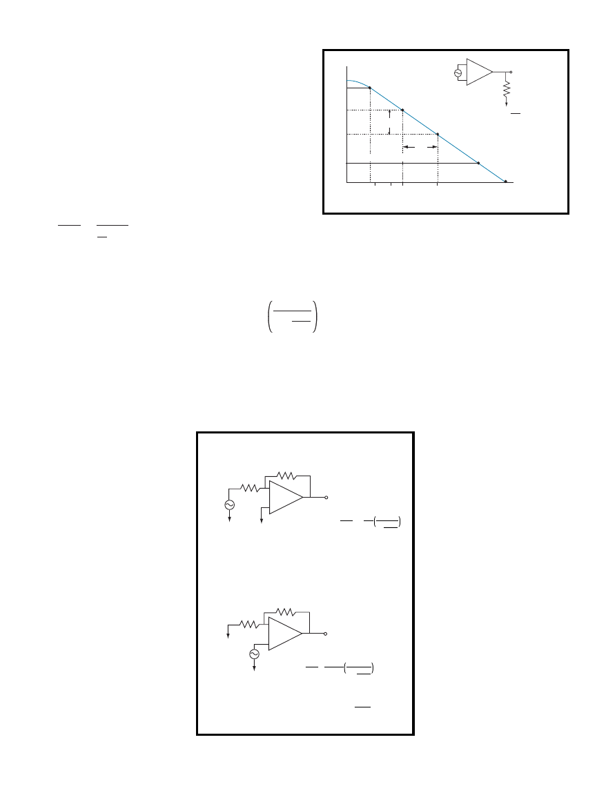
CIRCUIT CELLAR
®
Issue 120 July 2000
67
www.circuitcellar.com
60 dB (1000) and the bandwidth is 1
kHz, giving a GBW of 1 MHz. At C,
the gain is 40 dB (100) and the band-
width is 10,000 Hz, again with a GBW
of 1 MHz.
Now, how does op-amp open-loop
gain affect a circuit? First, op-amps
are rarely used in open-loop configura-
tion. So, let’s look back at the general
case of an amplifier in a feedback
configuration that I presented in Part 1.
There we saw:
G =
V
OUT
V
IN
=
1
1
A
+ H
[1]
Ideally, A >>1 leaving us with:
G = 1/H
[2]
A = amplifier gain
H = feedback factor
Equation 2 shows that, in the ideal
case, the gain of the circuit is depen-
dant only on the feedback network
and not on the amplifier. So, the op-
amp open-loop gain ideally would
have no effect on the circuit, assum-
ing its gain is infinite. Of course,
looking at Figure 2, you see that
the op-amp’s open-loop gain and
bandwidth are frequency-depen-
dent and far from infinite.
Let’s look at the noninverting
and inverting amplifiers to see
how ifinite and frequency de-
pendant op-amp open loop gain
ultamatly affect circuit perfor-
mance. In Figure 3, I present
two equations that point out the
effects of non-ideal op-amp
open-loop gain on circuit perfor-
mance (I spared you the control
theory and just presented the
equation).
Table 1 is the result of some
simple number crunching. Us-
ing the noninverting and invert-
ing circuits, I set a gain of 2 and
–2, respectively. I then calculate
the actual gain using the equa-
tions in Figure 3 at 1 kHz and
10 kHz. I repeat this at a gain of
20 and –20 (see Figure 4). In
Table 1, the open-loop gain is
for the TL071 from Texas In-
struments.
Note that even though the TL071
has a unity gain bandwidth of 5 MHz,
there is a significant error in accuracy
at 10 kHz, practically at higher gain.
The accuracy error can be split out as:
% error =
1
1 + 1
A
VL
× 100
[3]
The term A
OL
B is called the loop
gain, an important term. It can be
seen that the loop gain determines the
accuracy of the circuit. For 1% accu-
racy, A
OL
B would have to be 100 (40
dB), and if you had B = 1/10, then A
OL
would be equal to 1000 (60 dB). If you
wanted an accuracy of 0.1% then A
OL
B
would have to be 10,000 (80 dB). If B =
0.1 again this means that A
OL
would
have to be 100,000 (100 dB).
This establishes that, as long as
A
OL
B is large (ideally infinite), you
have no differential voltage at the
input terminals, they are at the same
potential, the famous virtual short
assumption. Therefore, the output
voltage is dependent only on the
closed-loop gain, with the open-loop
gain having no effect. If AvoB begins
to decrease, the ideal op-amp model
no longer applies, causing accuracy
errors.
SLEW RATE
If you apply a fast rise time
pulse or squarewave to the
input of the op-amp in Figure 5
(which is large enough to over-
drive the op-amp), the output
voltage will not be able to fol-
low the input. The output will
ramp or slew to the final value
at a rate known as the slew
rate. Slew rate is the maximum
rate of change of the output
voltage in response to a large
signal step at the input:
Slew Rate = dV/dt. [4]
Slew-rate limiting is caused
by the charging or discharging
of capacitance, and the fact that
there is a limited amount of
charging current the op-amp
can supply. Usually the limit-
ing capacitance is the frequency
compensation capacitor (exter-
nal or internal), however, de-
Figure 2
—Note the break
frequency about 100 Hz is a
result of the compensation
capacitor. The capacitor
dominates the frequency
response, thus the name
dominate pole, giving a fre-
quency response of –20 dB per
decade.
Figure 3
—The gain equations take into account the non-ideal nature of
the open-loop gain. The equations have two parts: the ideal gain and an
error term.
Gain (dB)
100
97
60
40
0
B
A
C
D
X10
X10
–
+
V
IN
V
OUT
Frequency (Hz)
approx 100
1K
10K
1M
A
OL
=
V
OUT
V
IN
Ideal closed-loop gain
Inverting
Non-inverting
–
+
V
IN
V
OUT
R
F
R
S
–
+
V
IN
V
OUT
R
F
R
S
V
OUT
V
IN
= R
F
R
S
1
1+ 1
A
OL
B
V
OUT
V
IN
=R
S+
R
F
R
S
1
–1+
1
A
OL
B
–
Where – A
OL
=
Op Amp open-loop gain
B
= feedback attenuation factor =
R
S
R
S
+R
F
A
OL
=
loop gain
a)
b)
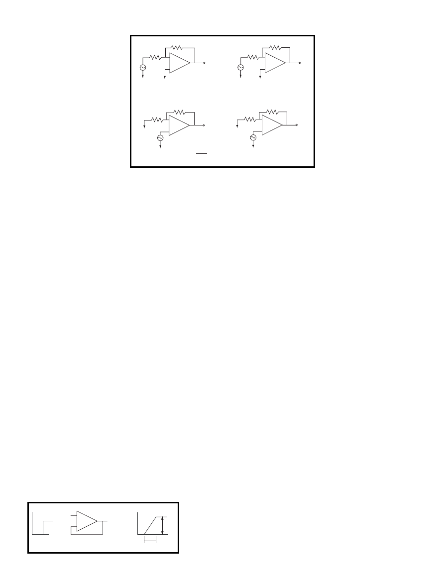
68
Issue 120 July 2000
CIRCUIT CELLAR
®
www.circuitcellar.com
Inverting
–
+
V
IN
V
OUT
2
Ω
1
Ω
–
+
V
IN
V
OUT
R
F
R
S
Ideal gain = – 2
R
S
R
F
1
Ω
1
Ω
Ideal gain = 2
–
+
V
IN
V
OUT
20
Ω
1
Ω
Ideal gain = – 20
R
S
R
F
–
+
V
IN
V
OUT
R
F
R
S
19
Ω
1
Ω
Ideal gain = 20
β
=
R
S
R
F
+ R
S
Figure 5
—Applying a step to the input of
an op-amp that is large enough to saturate
the input will cause the output voltage to
ramp up at a rate defined by the slew rate.
pending on the circuit, the
load capacitance may be the
limiting capacitance.
Slew rates range from a
few volts per microsecond to
several thousand volts per
microsecond. The test circuit
is the familiar unity gain
amplifier. Often this specifi-
cation is referred to as unity
gain slew rate. The unity
gain amplifier is the most
demanding test of an op-
amp’s slew rate.
To understand the mecha-
nism of slew rate, let’s once
again go back to the three-
stage model of the op-amp
shown in Figure 1.
The large input voltage step will
cause Q1 to saturation and Q2 to
cutoff. Therefore, all the current (I
T
)
passes through Q1 and Q3. Because of
the current mirror, Q4 also has I
T
flowing through it. Because Q2 is off,
off the current must flow in the com-
pensation capacitor (minus the small
base current of Q5, which for simplic-
ity I will ignore). As the compensa-
tion capacitor is charged, the output
voltage ramps linearly. If the op-amp
has a unity gain output stage, the
output voltage change is equal to the
rate of voltage change across the com-
pensation capacitor C
C
.
SR = It/C
C
[5]
From Equation 5 you can see why
the output voltage ramps linearity—
you have a constant current (I
T
) charg-
ing a capacitor C
C
. In order to
maintain the constant current, the
input differential voltage (error volt-
age, to be more correct, slew rate is
tested in closed loop) must be large
enough to keep the op-amp overdriven
(see Figure 6). For bipolar op-amps,
this is generally not an issue because
this minimum error voltage is typi-
cally in the 100-mV range. However,
Figure 4
—These circuits are used to calculate the effect on non-ideal loop gain. The
results can be seen in Table 1.
signal, knowing that the
741 has a slew rate of one
volt per microsecond.
Figure 7b shows the
same unity gain amplifier,
but this time I applied a
sinewave input. If the
maximum slope of the
sinewave (which occurs at
the zero crossing) is less
than or equal to the slew
rate of the op-amp, the
output will be distortion-
free. In turn if the maxi-
mum slope of the
sinewave is greater than
the op-amp slew rate, then
output distortion will
occur.
Finally, if the slope of the sinewave
is much greater than the op-amp slew
rate, severe distortion at the output
will occur. Slew rate distortion starts
at the point were the maximum slope
of the sinewave equals the slew rate.
The slope of the sinewave is related to
its frequency.
You can now see how slew rate
affects both the op-amps maximum
distortion-free output voltage swing
and maximum distortion-free operat-
ing frequency. In Figure 7b, if you
apply an input sinewave of peak volt-
age (V
P
) and frequency (f), then the
output will be:
V
O
=V
IN
=V
P
sin(2
π
ft)
[7]
The rate of change is:
dV/dt = 2
π
fV
P
cos(2
π
ft)
[8]
and the maximum slope occurs at the
zero crossing of the sinewave,
cos2
π
ft=1:
dV/dt(max) = 2
π
fV
P
[9]
Now, let’s equate the maximum
slope of the input (or output)
sinewave to the slew rate (SR):
SR = 2
π
fV
P
[10]
Therefore, the maximum sinewave
frequency that an op-amp in unity
gain configuration can handle distor-
tion-free is:
a)
b)
for some JFET and MOSFET input op-
amps this minimum error voltage can
be as high as 1 to 3 V.
Equation 5 also points out that this
is the maximum slew rate. The op-
amp cannot supply more courrent
than it to charge the compensation
capacitor. Therefore:
Slew Rate(max) = dV
o
/d
t
= I
t
/C
c
[6]
Equation 6 holds true for most op-
amps, however, as is always the case
with op-amps, there are input struc-
tures that are the exception.
Because the compensation capaci-
tor is a limiting factor op-amp, de-
signers often reduce the
compensation capacitor to improve
slew rate. This raises stability issues,
particularly at unity gain. Another
way designers increase slew rate is to
increase the current that the differen-
tial pair can supply, however, this
will increase bias currents and power
consumption.
Now, let’s see how slew rate af-
fects circuits. In Figure 7a, there is a
unity gain amplifier that uses the
world’s most studied op-amp, the
741. If you apply a pulse to the input,
you can easily determine the output
c)
d)
t=0
–
+
t=0
∆
t
AV
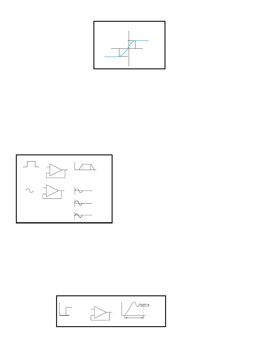
CIRCUIT CELLAR
®
Issue 120 July 2000
69
www.circuitcellar.com
–
+
741
10 V
10 µS 10 µS
–
+
Slope << SR
Slope > SR
Slope >>SR
10 V
Fmax = SR/2
π
V
P
[11]
FULL POWER BANDWIDTH
If V
P
is equal to the full output
span of the op-amp, which is limited
by the power rails, another op-amp
specification is defined—full power
bandwidth (FPBW). FPBW is the maxi-
mum frequency at which the op-amp
can deliver full-rated output voltage
distortion free without the occurrence
of slew rate limiting:
FPBW=SR/2
π
V
P
max
[12]
Now, let’s look at how slew rate
affects full power bandwidth. I’ll look
at three op-amps. The 741 with its 1
V/µs slew rate and maximum output
of ±13 V, the Texas Instruments
THS4001 with a slew rate of 400 V/µs
and output of ±13 V, and also the
Texas Instruments THS3001 current
feedback op-amp with a slew rate of
6500 V/µs and ±13 V output. Doing
the simple FPBW calculation:
Op-Amp
Slew Rate
Full Power
(V/µS)
Bandwidth
741
1
12.25 kHz
THS4001
400
4.9 MHz
THS3001
6500
79.6MHz
Here, you can clearly see the affect
of slew rate. These are general num-
bers where loads will have an affect.
Testing for slew rate and FPBW is
fairly simple—apply a large pulse or
squarewave to a voltage follower and
look at the output. The slew rate can
be determined from the edges of the
output pulse (see Figures 5 and 7).
Manufacturers provide these graphs in
their datasheets. As the
Figures point out, as
slew rates increase, there
is a greater demand
placed on the test cir-
cuits. The input test
pulse has a finite rise
and fall time.
For completeness, let
me point out that the
response of the voltage
follower to a voltage step
at its input may be more
complicated than I
present in Figure 5. [1]
As you look through
manufacturers
datasheets, you will see
that slew rate depends on several
factors. Circuit configuration is one of
these factors. The inverting amplifier
has a greater slew rate than the
noninverting amplifier. In the invert-
ing configuration, the inputs are at
virtually ground, so do not signifi-
cantly change voltage when a step is
applied (as opposed to the
Figure 6
—In order for the input of an op-amp to
saturate a slew rate limit, there must be a minimum
differential across the input. This value can be as low as
a few hundred millivolts for bipolar to a couple of volts
for JFET and MOSFET devices.
100 mV
–100 mV
Output slew rate
Differential voltage
Maximum
+ Slew Rate
Maximum
– Slew Rate
Figure 7
—If a pulse is applied to an op-amp with a known slew rate, the
output is predictable. In the above case it will take 10 µs for the output to
reach 10, given a slew rate of 1 V/µs.
Figure 8
—Applying a fast
rise time pulse or square-
wave to the input of this
op-amp will result in the
output voltage not being
able to follow the input.
–
+
V
IN
V
OUT
Error band
Settling line

70
Issue 120 July 2000
CIRCUIT CELLAR
®
www.circuitcellar.com
noninverting inputs that do change
value). Power supply voltage has an
effect; the current source in the input
stage is not perfect, and as the power
supply voltage rises, more current is
available to charge the compensation
capacitor and therefore the slew rate
increases.
SETTLING TIME
Slew rate measures how fast the
output voltage can change. Settling
time is a measure of how long it will
take the output to reach its final
value. Settling time is precisely de-
fined as the time it takes for the out-
put voltage to come to and stay
within a certain error band, in re-
sponse to a step at the input (see Fig-
ure 8).
The waveforms in Figure 8 show
that there are two components to
settling time. The first part of the
curve is slew-rate limited. As long as
the input is overdriven, the output
will ramp up at a rate limited by the
slew rate. The second part of the
curve shows the classic overshoot and
undershoots associated with damped
oscillation. This part of the curve is
quite complex because it’s nonlinear
and a function of many time con-
stants. The time it takes the output to
Figure 9
—This op-amp is used to provide a buffer
between a MUX and the input to an ADC.
Table 1
—Here are the
results of calculating the
effects on the non-ideal
open-loop gain circuits
shown in Figure 4.
REFERENCES
Art of Electronics second edition,
Horowitz and Hill, Cambridge
Press, 1990, ISBN 0-521-37095-7.
Understanding Operational Ampli-
fier Specifications, Jim Karki,
Texas Instruments White Paper
sloa011, 1998.
Operational Amplifiers and Linear
Integrated Circuits, Coughlin and
Driscoll, Prentice Hall, 1977.
Op-amp Cookbook
, Sams, 1986,
W. Junk.
TI Analog seminar handbook,
1999.
“The Monolithic Op-amp.” A
tutorial study, James E. Solomon.
IEEE Journal of Solid State Cir-
cuits
, Dec 1974, page 314-332.
Inverting
frequency
A
OL
from
A
OL
B
1/(1 + 1/A
OL
B)
Ideal gain
Actual gain
% error
in kHz
T
LO
71
Inverting
1
5000
2500
0.9996
–2
–1.992
0.04%
10
500
250
0.996
–2
–1.992
0.4%
1
5000
250
0.996
–20
–19.92
0.4%
10
500
25
0.961
–20
–19.23
3.85%
Noninverting
1
5000
5000
0.9998
2
1.9996
–0.02%
10
500
250
0.998
2
1.996
–0.2%
1
5000
263
0.996
20
19.92
–0.4%
10
500
260.3
0.963
20
19.26
–3.66%
Mux
ADC
+
–
…
Joe DiBartolomeo, P.Eng., has more
than 15 years of engineering experi-
ence. He is currently employed by
Texas Instruments as an analog field
engineer. You may reach him at
j-dibartolomeo@ti.com.
settle within the error band is the
settling time.
For op-amps, there is no obvious
error band. An error band must be
defined—common values are 0.1%,
0.01%, and 0.001%. But the true error
band is defined by the application.
One area where op-amp settling
time is a design consideration is in
data conversion. Op-amps are com-
monly used at the input of analog to
digital converters (ADC) in an anti-
aliasing filter and in reconstruction
filters at the output of digital to ana-
log converts (DAC). In data conver-
sion applications, the error band is
well defined—it is the least signifi-
cant bit (LSB). There is no use paying
for a fast data converter only to have
the op-amps settling time be the larg-
est error source.
Let’s look at a simple example, the
op-amp in Figure 9 is used as a buffer
between a mux and the input to an
ADC. Because as the mux switches
through input channels there is a good
chance the op-amp input will see a
wide voltage range. The ADC sets
both the error band and the settling
time. The op-amp must settle to
within one-half LSB (error band) in
less than one ADC sampling interval
(settling time).
In this article, I covered some AC
op-amp specifications. As was the
case with the DC specifications, the
op-amp AC specifications are greatly
affected by the fact that op-amps are
normally used in a negative feedback
configuration. I pointed this out
many times in the series, but I don’t
think you can overstate feedback’s
importance.
Also, the op-amps internal struc-
ture gave some insight into the AC
specification, as it did with the DC
specification. It’s important that you
have a basic understanding of op-amp
structures.
Finally, I tried to show how the
op-amp specifications affected a cir-
cuit because, after all, the circuit is
the important issue. You will find
that there are many tradeoffs in se-
lecting an op-amp. Make sure that
you are not considering an op-amp
specification that your circuit ren-
ders meaningless.
I
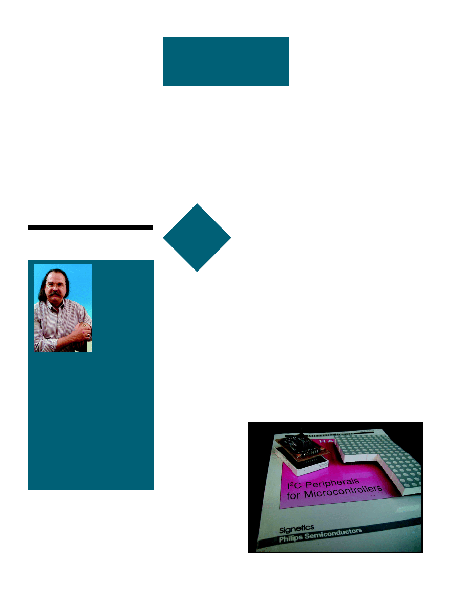
72
Issue 120 July 2000
CIRCUIT CELLAR
®
www.circuitcellar.com
FROM THE
BENCH
Jeff Bachiochi
DFPs: Riding
the Wave of
the Future
Jeff set
out to
build a
reus-
able pe-
ripheral I
2
C device
that he could recycle
in future projects.
The practicality of
LED character dis-
plays made the appli-
cation choice easy.
am a devoted
fan of decentral-
ized processing. I
believe this is the hard-
ware equivalent of software functions.
Yet, I can’t remember the last time I
was able to drop a prewritten module
into a new software project (they al-
ways need a tweak). This may be a
lack of programming expertise on my
part. The idea of reusable code func-
tions is a good one.
Of course, using DFPs (devoted
function processors) isn’t a prudent
approach if the application is simple
or without the need for speed. How-
ever, often multiple processors that
handle specific tasks, rather than a
single, cranked-up,
super-charged proces-
sor, can deal with an
application more eas-
ily. The modular ap-
proach makes sense
when you can start
reusing the hardware
and skip most of the
designing and testing.
A good example of this
is the LCD display.
Early displays re-
quired constant multi-
plexing by the main
processor. Display
processors were then
added to LCDs, remov-
ing the high activity burden from the
main processor. Now, many LCDs
have an integral serial interface. Actu-
ally, it’s a second processor added to
the LCD, allowing communications
through a serial connection rather
than the parallel I/O interface of the
original display processor. With each
additional hardware layer, the user
interface is simplified. Of course,
there is a tradeoff between extra cost
and ease of use.
ALTERNATE INTERFACING
Originally designed as a means of
simplifying the I/O bus, the I
2
C proto-
col is only one of many synchronous
serial protocols. Designers are con-
stantly discovering the benefits of I
2
C
peripherals. The protocol’s ability to
handle both a master/slave and multi-
master arrangement with two wires
makes it a winner. As developers of
the I
2
C bus, Philips Semiconductor
has promoted its growth by develop-
ing many peripherals. These have
been designed for specific I/O tasks,
like expanding digital or analog I/O.
Although each specific I
2
C device
comes with a predefined address and a
10-bit limit to the addressable de-
vices, as a systems designer, I know
what will and won’t be used. I can use
any of the unused addresses for pe-
ripheral devices I design.
This month, I wanted to design a
peripheral I
2
C device that can be
reused in other projects. You will
find I
2
C support for LCDs and even a
few seven-segment LED displays. I
i
Photo 1—
These 5 × 8 dot modules can be stacked vertically or horizontally.
This month’s project was designed to fit on the rear of each display module.
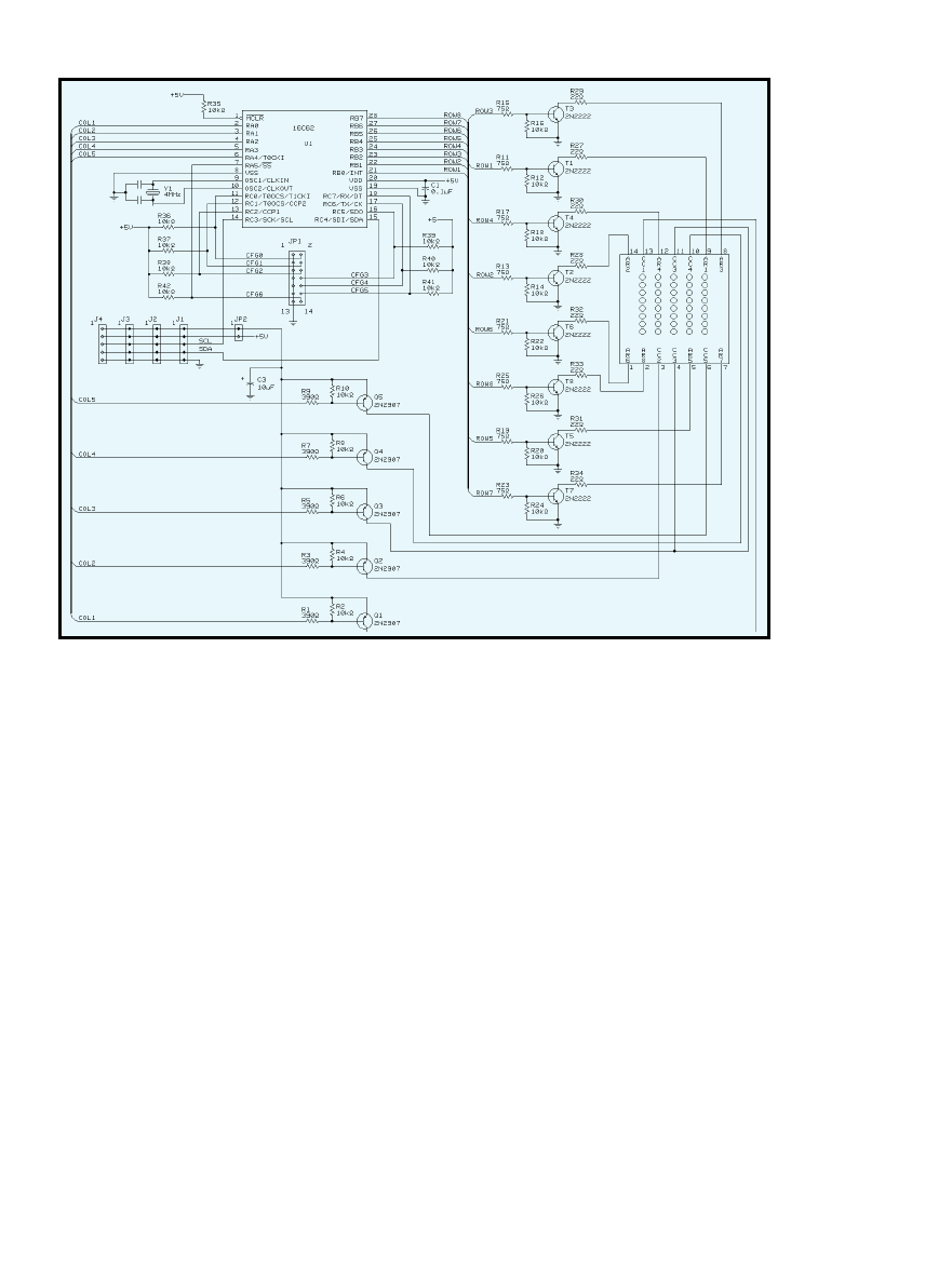
CIRCUIT CELLAR
®
Issue 120 July 2000
73
www.circuitcellar.com
want to take this further to include
the 5 × 7 (or 5 × 8) dot large-character
display (see Photo 1).
Ten years ago, I created a project
with 5 × 8 dot displays. That project
required a single processor to handle
a user interface, and multiplex all the
LEDs. As a standalone message dis-
play, this arrangement was great.
However, it required a minimum of
eight displays. And because it re-
quired a separate processor, the
project wasn’t cost effective for add-
ing as a peripheral display.
I took a different approach this
month. I want this display peripheral
to be totally self-contained. I will do
this by adding an I
2
C interface to
each 5 × 8 display module. You de-
cide how many displays are necessary
for your application. Each module
will multiplex its own 5 × 8 matrix
of LEDs.
Today, many microprocessors can
sink or source up to 25 mA. Al-
though 25 mA seems like plenty of
current for most LEDs, after being
multiplexed, the current must be
increased to get the same relative
intensity as an LED that is driven
continuously. That’s because they’re
on for only a fraction of the total
scan time.
If all the LEDs are on, the micro-
processor won’t be able to handle the
current necessary to keep these LEDs
happy. For this reason, external tran-
sistors enable the LEDs in a row-
column matrix. Five source
transistors and eight sinking transis-
tors create the matrix.
My first idea was to multiplex by
columns, enabling each sourcing
transistor in sequence and placing
eight bits of column data on the sink-
ing transistors for each column en-
able. This would produce 8× current
if all LEDs are on.
Conversely, if the eight rows are
enabled in sequence and 5-bit data
enables the sourcing columns, the
maximum current would be 5×. As-
suming we keep the individual LED
current the same in both schemes,
the second scheme would reduce the
average and peak current require-
ments (and brightness) by a factor of
5
/
8
because of the
1
/
8
(instead of
1
/
5
)
duty cycle. Note that to maintain
constant brightness, the current
through each LED would need to be
increased by a factor of
8
/
5
, making
the average and peak current the
same in both schemes.
I
2
C CONFIGURATION
Many microprocessors with SPI
ports support multiple serial proto-
cols. Although the least expensive
micros do not have SPI ports, SPI only
adds about a dollar to the cost in
small quantities. This project is I/O
intensive, so the lower pin count
micros can’t easily be used. I need at
least 15 bits.
I chose to use Microchip’s 16C62
because it has 22 I/Os and is avail-
able for under $5 in SMT packaging
(SOIC and smaller SSOP). The oppor-
tunity to use multiple displays is an
advantage and the extra I/O will al-
low external address selection. Each
display could be permanently ad-
dressed internally, but that’s a pro-
Figure 1
—The 22
bits of I/O are
configured as: port
A0–4 is the column
enable outputs; port
B0–7 is the row
enable outputs; ports
A5, C0–2, and C5–7
are user-configured
I
2
C address selection
inputs; and port C3–4
is the I
2
C bus con-
nections.

74
Issue 120 July 2000
CIRCUIT CELLAR
®
www.circuitcellar.com
gramming hassle and does not make
for easy inventory control.
One of the micro’s registers is the
SSPADD
. This register is used as an
address comparison on the first byte
(address) of any I
2
C transmission the
hardware sees on the I
2
C data/clock
interface lines. A match has the abil-
ity to interrupt the micro. This inter-
rupt can be used to begin paying
attention to the I
2
C hardware in an
attempt to process a request. I
2
C mes-
sages to any other address are simply
overlooked by the hardware, and the
micro never knows about them.
The simplest I
2
C devices commu-
nicate with a 2-byte protocol. The
master sends a single byte address,
which also includes a read or write
indicator bit. The master sends a sec-
ond data byte if the write bit in the
previous address byte was cleared. Or,
the slave transmits a second data byte
if the read bit in the previous address
byte was set.
As long as the master and slave
devices both understand the protocol,
the length of the packet can be
greater. Many slave devices have mul-
tiple registers that can be accessed.
Multiregistered devices usually have a
2/3-byte protocol. That is, there is
usually a pointer within the slave
device to select the working register.
The first data byte following an
I
2
C write is used to select this regis-
ter (or deliver a command), and the
remaining byte(s) become data. Most
devices will autoincrement this regis-
ter, allowing multiple data bytes to
be placed in incrementing locations.
During a
read function, the select
register will be used as a pointer to
where the data will come from. Stor-
age devices (i.e., RAM or EEROM)
use this protocol to allow multiple
bytes of data to be transferred in a
single packet.
This project uses a register pointer
protocol such that each 8-bit column
can set to any 8-bit byte. The registers
implemented in this project are 0–5,
where registers 1–5 contain the actual
data for columns 1–5.
Register 0 is a special case register.
This register, when written to, will
use the value as an index for a look-up
table that will hold values transferred
to the column 1–5 registers. This
special register allows predetermined
characters to be displayed with mini-
mum communications. Although this
is great for displaying alphanumerics,
it doesn’t work for all possible dot
combinations. This is similar to char-
acter mode versus graphics mode on
an LCD.
I/O
In Figure 1, the 22 bits of I/O are
configured as: port A0–4 is the col-
umn enable outputs; port B0–7 is the
row enable outputs; ports A5, C0–2,
and C5–7 are user configured I
2
C ad-
dress selection inputs; and port C3–4
is the I
2
C bus connections.
Upon initialization of the system,
the user configured I
2
C address selec-
tion inputs are sampled and an ad-
dress byte for the device is assembled
and stored in
SSPADD. From this point
on, the device will respond only to
this address. The master (or more
specifically, the protocol used by the
master) must be able to use the regis-
tered I
2
C protocol.
Figure 3—
This is the data for the columns. Row eight
is enabled.
ROW_DATA=11h xxx10001
1 o * * * o
0 o o o o o
0 o o o o o
0 o o o o o
0 o o o o o
0 o o o o o
0 o o o o o
0 o o o o o
COL_MASK=80h _|
o * * * o
o o * o o
o o * o o
o o * o o
o o * o o
* o * o o
o * o o o
o o o o o
COL1=04h__|
COL2=82h____|
COL3=FCh______|
COL4=80h________|
COL5=00h__________|
Figure 2—
Here’s the data for “J”.

CIRCUIT CELLAR
®
Issue 120 July 2000
75
www.circuitcellar.com
Figure 4—
This shows building ROW_DATA based on the complement
of COL_MASK and columns 1–5.
COL_MASK=40h
01000000
|
COL1=04h
00000100
COL2=82h
10000010
COL3=FCh
11111100
COL4=80h
10000000
COL5=00h
00000000
|
ROW_DATA=1Bh xxx11011___|
DATA READY
Interrupts will be generated
for each byte received in the
packet if there is a match on the
address byte. The I
2
C interrupt
routine must be able to service
this routine in nine clock pulses
(as fast as ~23 µs), or an overflow
situation may occur. Because
every byte sent in the packet is
acknowledged, the master knows
when something goes wrong. The
master’s software can determine
when a packet needs to be sent again
as a result of a transmission error.
The slave’s interrupt routine must
check the D/A bit to determine if the
data is a data or address byte. The
routine tracks the data byte count so
the received data is used correctly. The
first data byte must be placed in the
register pointer. The next byte(s) must
be placed in the pointed-to register(s)
and autoincrement the pointer.
A slave I
2
C device doesn’t require
any active internal resources to capture
I
2
C transmissions. Data is clocked into
the shift register (SSPSR) by the
master’s toggling of the SCL line.
However, when the I
2
C transmission is
a
read function, the slave must place
data into the SSPSR so that the master
can shift it out of the slave.
The slave can halt the master’s
clock toggling by holding the SCL line
low. Ordinarily the slave does not
have to touch the I
2
C clock line. This
is necessary because the slave can’t
get the requested data back into
SSPSR before the master’s next clock
cycle. The master samples the SCL
line after it releases it (the pullup on
the SCL line would normally pull it
high). If the master finds it still low,
it knows the slave is requesting a hold.
GOT DATA?
OK, now you have bit-mapped data
in the five column registers, COL 1–5
(see Figure 2). This may have come as
a write to register 0, in which case the
look-up table was used to fill in regis-
ters 1–5. The five column registers
may have been transmitted separately
to allow full control of the 35 LEDs.
How is the data in those registers
reflected on the 5 × 7 LED display? A
secondary task handles multiplexing
the display on a periodic interrupt.
The periodic interrupt is provided by
timer0. When each timer overflows,
the background task executes to up-
date one of the eight rows with the
column data for that row.
The task begins with Port B being
cleared. Clearing this port disables all
eight row-sinking transistors.
ROW_DATA is written to Port A.
Port A’s output bits control the five
column sourcing transistors. A one
disables the source voltage to that
column, and a zero enables the source
voltage to that column.
Because the eight row-sinking tran-
sistors are disabled at this time, no
LEDs are on, even if the source transis-
tor has been enabled. COL_MASK is a
register that does double duty. This
mask is a single bit that is shifted left
once each timer0 interrupt. After
shifted into the carry, an extra shift
moves it back into the LSB position.
COL_MASK enables a single row-
sinking transistor (see Figure 3) each
time timer0 overflows. This action
allows all the LEDs in a single row to
be enabled if their corresponding col-
umn-sourcing transistor is enabled.
Now, the ROW_DATA register can
be preloaded with the next row’s data.
This is where COL_MASK is rotated,
to point to the next row to be enabled.
The ROW_DATA register is initial-
ized with a one. COL_MASK is then
ANDed with each column register,
and if the mask result is not zero, the
corresponding bit in the ROW_DATA
is cleared (zero enabled source transis-
tor). Take a look at Figure 4.
STATIC VS. MOVING DISPLAY
This 5 × 7 LED display module is a
static display. As a peripheral, you
send it data and the module displays
Jeff Bachiochi (pronounced“BAH-key-
AH-key”) is an electrical engineer on
Circuit Cellar’s engineering staff. His
background includes product design
and manufacturing. He may be reached
at jeff.bachiochi@circuitcellar.com.
SOURCE
PIC16C62
Microchip Technology Inc.
(888) 628-6247
(480) 786-7200
Fax: (480) 899-9210
www.microchip.com
the bit map of the data. If noth-
ing else is ever sent to the mod-
ule, the LEDs remains in a static
state, even though there are eight
static displays (each row is en-
abled in sequence).
Animating the display re-
quires sending new COL 1–5
data. For example, to emulate a
20-character (100-column) scroll-
ing display, at five characters per
second (25 columns), you would
write to the 100 columns, 25 times
per second.
1/25 s is 40 ms, so you would write
to all 100 columns in 40 ms. That’s
(40 ms/100) 400 µs for each write.
This rate can be handled easily, it’s
only about 20% of the available pro-
cessor time.
Bar graphs are another use of dot
matrix displays. A simple graphic
mask applied to the display can be
used to group together rows or col-
umns. The display (or multiple dis-
plays) can be mounted vertically or
horizontally, depending on your ar-
rangement.
DFP
If you scratched you head when
you read the title of this column be-
cause you never heard of “devoted
function processors”, you’re not
alone. I coined this phrase to indicate
this special use of a processor. We’re
now seeing micros with totally inter-
nal oscillators; neither crystal resona-
tor nor RC components are necessary.
When these are used, the fact that the
device is a processor becomes hazy.
At this point, the DFP becomes just
another component.
I

76
Issue 120 July 2000
CIRCUIT CELLAR
®
www.circuitcellar.com
c
atchy title,
don’t you think?
That’s why I resur-
rected it from way back
in ’93 (Circuit Cellar 39). I figure
there’s nothing wrong with plagiariz-
ing my own stuff. Besides, what better
name to describe the Programmable
System Devices (PSDs) from Wafer-
scale that combine memory, I/O, and
programmable logic in one chip?
As I discussed then, the concept of
combo chips harkens almost to the
dawn of silicon. Old-timers may re-
member that both Intel and
Motorola offered such devices
(i.e., Intel made the 8155/
8355/8755 and Motorola made
the 6846) along with their
microprocessors to support
simple two- and three-chip
system designs. The combo
chips had various combina-
tions of memory (ROM,
EPROM, or SRAM), parallel
I/O, counter/timers, and so on.
Whatever became of them?
The devices of the ’70s got
caught in a squeeze play be-
tween more and less.
On one hand, single-chip
microcomputers such as the
8048, 8051, 6805, and 6801
emerged to meet the needs of
designers searching for inte-
gration. Meanwhile, applica-
tions that needed more memory than
what an MCU had to offer turned to
the JEDEC standard byte-wide
EPROMs and SRAMs that remain
popular to this day. This left Wafer-
scale to soldier on with the PSDs.
So, why bother devoting an article
to seemingly niche combo chips?
Well, the timing is right with Wafer-
scale spinning a new generation of
products. More importantly, I wonder
if the market dynamics are changing
in ways that make the combo chip a
more practical solution today than it
was in the past.
ANY WAY YOU SLICE IT
Despite all the talk about System-
On-Chip, I believe multichip solu-
tions still have hidden talent. In fact,
multichip design options are getting
more interesting by the minute.
Until recently, the recipe was cut
and dry. Combine your favorite con-
troller with some standard memories
and supplement with a dash of periph-
eral logic to handle your application’s
unique I/O needs.
The basics of CPU, memory, and
I/O haven’t changed, but the one-on-
one correspondence of function and
chip can no longer be taken for
granted. The emergence of FPGAs
with built-in controller cores or
memory is one example of a conven-
tion-busting alternative.
Swiss Army
Chip
When it
comes to
combo
chips that
have
what it takes to make
it, Tom thinks the suc-
cess or failure of such
chips may have a lot
more to do with what
else is going on in the
world of silicon.
SILICON
UPDATE
Tom Cantrell
Programmable System Devices
Input Source
Input Name
Number
of Signals
MCU address bus
A [15:0]
16
MCU control signals
CNTL [2:0]
3
Reset
RST
1
Power down
PDN
1
Port A input
PA [7-0]
8
Port B input
PB [7-0]
8
Port C input
PC [7-0]
8
Port D input
PD [3:0]
4
Port F input
PF [7:0]
8
Page register
PGR [7:0]
8
Flash programming
Rdy/Bsy
1
status bit
Note: The address inputs are A [19:4] in
80C51XA mode.
Table 1
—The on-chip PLDs have access to most of the important
control signals. Note that signals that aren’t needed in your logic
equations can be configured as “no connects” to reduce power
consumption.
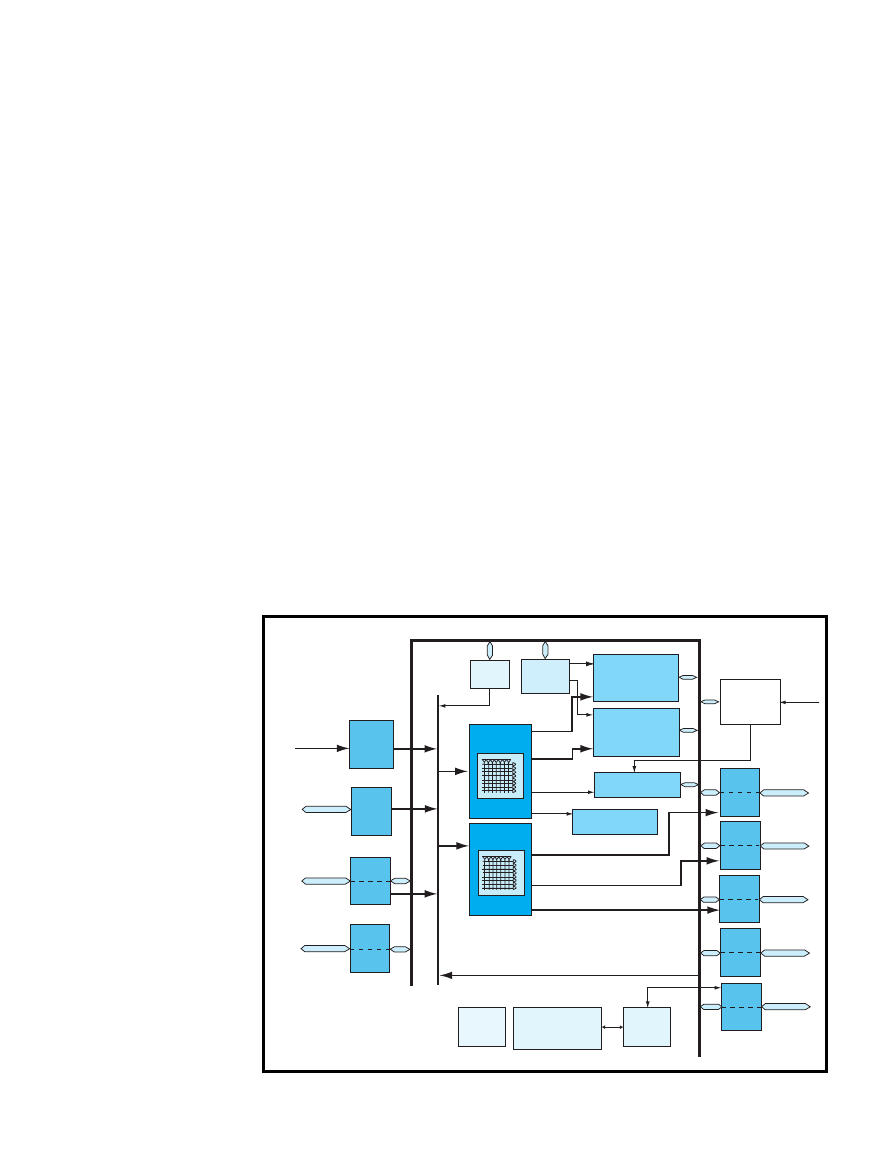
CIRCUIT CELLAR
®
Issue 120 July 2000
77
www.circuitcellar.com
The same holds true for PSD. Al-
though its main role is memory, it
also includes enough programmable
logic and I/O to achieve few-chip
solutions that make sense.
The challenge for the PSD remains
as it did back in ’93, hitting the sweet
spot between applications that fit
easily in a high-integration micro-
controller and those that call for a
commodity-memory solution.
The concept is the same, but the
latest PSDs, such as the PSD4135 (see
Figure 1), bring new features to the
party. The biggest change is the
switch from yesterday’s OTP EPROM
technology to flash memory, which
goes hand in hand with JTAG-based
in-system and in-application program-
ming. The PSD4xxx parts also accom-
modate the trend that bigger is better
with full support for 16-bit processors.
The ’4k’s claim to fame is that it
incorporates a hearty amount of flash
memory comprising a 4-Mb (256 K ×
16) main block and a 256-Kb (16 K ×
16) secondary block. The former is
subdivided into eight 32K × 16 and the
latter into four 4K × 16 blocks, or
sectors. These blocks define
the minimum erase granular-
ity, but programming is ac-
complished one word at a
time. There’s also a 64-Kb
(4K × 16) block of SRAM.
According to the preliminary
version of the ’4k datasheet,
both 5-V and 3-V versions are
available. As usual, the
higher voltage parts are
faster, available in 70- and
90-ns speed grades versus
90 and 120ns for low voltage
parts.
I noticed one possible
gotcha in the AC specs,
though. The access time is
longer in certain situations,
such as the first cycle after
power-up reset and after com-
ing out of low-power mode.
This could cause some
headscratching if your timing
is tight.
Write endurance for the
flash memory is 100k cycles,
much more than required to
handle software bugs and
updates. Indeed, for many applica-
tions, 100k cycles are enough to
handle EEPROM-like dynamic data
storage such as setup or tuning param-
eters. For nonvolatility without write
limits, another option is battery-back-
ing the on-chip SRAM. A pin is pro-
vided for connecting the battery, and
standby current is only 1 µA all the
way down to 2 V.
To manage access to various on-
and off-chip resources, the ’4k incor-
porates a few thousand gates of pro-
grammable logic. The Decode PLD
(DPLD) generates chip selects for the
on-chip memory blocks while the
General Purpose PLD (GPLD), as its
name implies, is free to handle other
application tasks. Both PLDs share a
common input bus of 66 signals (both
true and inverted) as shown in
Table 1. Note that the write endur-
ance is only 1000 cycles for the PLDs,
but that shouldn’t be a problem in
most applications.
The ’4k has a number of features to
address the never-ending desire for
lower power consumption. The PLD
can be set up in turbo or non-turbo
mode, trading speed for power. Fur-
thermore, software can force the issue
by dynamically disconnecting inputs
to the PLD array. Observe that de-
asserting the chip select input (CSI)
shuts off the memories but not the
PLDs. There’s also an automatic
power-down mode that relies on a
counter driven by an external signal
(see Figure 2) to detect a lack of MCU
activity. When the counter times out,
the part goes into a 50-µA (typical
5-V) standby mode.
Besides reprogrammability, another
benefit of flash memory is that it
enables the use of the latest surface
mount packaging (80-pin TQFP). Parts
can go directly from the tube onto the
circuit board without the need for a
separate programming step, which
generally limits packaging to options
that can be socketed easily, such as
DIP or PLCC.
The 80-pin package also means
there’s plenty of I/O capability on
hand with a total of 52 I/O pins avail-
able in addition to the 16-bit multi-
plexed address and data bus and
dedicated control lines. Besides I/O,
Program
MCU bus
interface
AD I/O
port
Program
port
Port
G
Program
port
Port
F
CNTL0,
CNTL1,
CNTL2
AD0–AD15*
PF0–PF7
PG0–PG7
PLD
input
bus
Page
register
Flash decoder
PLD (DPLD)
Flash ISP PLD
(GPLD)
66
66
Embedded
algorithm
4 Mb main flash
memory
8 sectors
256 Kb secondary
flash memory
(boot or data)
4 sectors
Sector
selects
Sector
selects
64 Kb battery
backup SRAM
Runtimer control
and I/O registers
SRAM select
CSIOP
Power
management
unit
VSTDBY
(PE6)
Program
port
Port
A
Program
port
Port
B
Program
port
Port
C
Program
port
Port
D
Program
port
Port
E
GPLD output
GPLD output
Global
config. and
security
PLD, configuration
and flash memory
loader
JTAG
serial
channel
GPLD output
PA0–PA7
PB0–PB7
PC0–PC7
PD0–PD3
PE0–PE7
I/O port PLD input
Address/data/control bus
* Additional address lines can be
brought into PSD via Port A, B, C, D, or F
Figure 1
—The Programmable System Device from Waferscale, which combines flash memory, SRAM, and programmable logic, is
a novel take on the silicon integration trend.
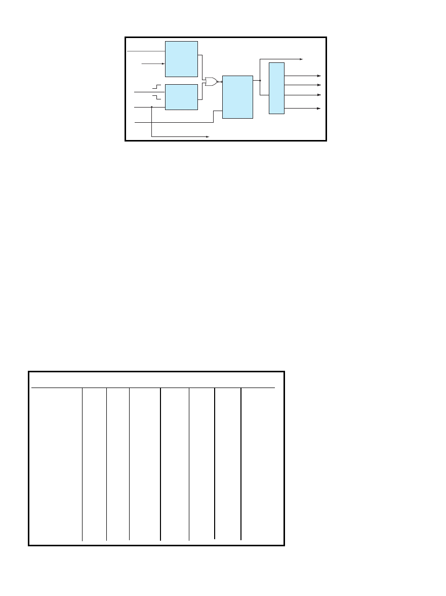
78
Issue 120 July 2000
CIRCUIT CELLAR
®
www.circuitcellar.com
MCU
CNTL0
CNTL1 CNTL2
PD3
PDO**
ADI00
PF3-PF0
68302, 68306
R/W
LDS
UDS
*
AS
-
*
68330, 68331
R/W
DS
SIZ0
*
AS
A0
*
68,332 68340
68LC302
WEL
OE
WEH
AS
-
*
68HC16
R/W
DS
SIZ0
*
AS
A0
*
68HC912
R/W
E
LSTRB
DBE
E
A0
*
68HC812***
R/W
E
LSTRB
*
*
A0
*
80196
WR
RD
BHE
*
ALE
A0
*
80196SP
WRL
RD
*
WRH
ALE
A0
*
80186
WR
RD
BHE
*
ALE
A0
*
80C161
WR
RD
BHE
*
ALE
A0
*
80C164-80C167
80C51XA
WRL
RD
PSEN
WRH
ALE
A4/D0
A3-A1
H8/3044
WRL
RD
*
WRH
AS
A0
-
M37702M2
R/W
E
BHE
*
ALE
A0
*
various options allow for
using the ports as either
extra address inputs or
outputs. As inputs, they
support non-mux bus con-
trollers or those with more
than 16 address lines. For
mux-bus controllers, the
I/O ports can deliver
latched address outputs,
eliminating the need for an
external latch in expanded
systems. The ports also
offer combinations of pro-
grammable output modes
including totem-pole, open-collector,
and limited slew rate. All in all, the
’4k is much less likely to cramp your
style than the earlier 44-pin package.
THE IN CROWD
Frankly, even ignoring the handling
issues, the earlier generation OTP
parts were a pain to program. The
procedure not only required a separate
high-voltage (12.75-V) programming
supply but also other intricate machi-
nations, such as carefully walking V
CC
through a five-step sequence between
4.5 and 6.5 V! Needless to say, one of
the challenges early PSD users faced
was finding a programmer beyond the
pricey $1765 unit sold through
Waferscale. It took a while for the
PSD to garner widespread support
from a variety of popular third-party
programmers.
Today, with flash memory overtak-
ing EPROM as the nonvolatile
memory technology of choice, in-
system programming (ISP) is all the
rage. It is advantageous to eliminate
the separate handling and program-
ming step, not to mention the expen-
sive hard-to-find programming
hardware. Furthermore, the re-flash
option allows for easy field upgrades
and fixing bugs.
The main requirement for ISP is to
have a dedicated serial bus for pro-
gramming that minimizes the number
of pins involved in making the con-
nection. The ’4k relies on a variation
of JTAG that only requires three sig-
nals (CLOCK, DATA IN, and DATA
OUT) to fill the bill.
There are a couple extra
signals, TSTAT and
TERR, provided specifi-
cally to assist program-
ming. But, they are
offered as a convenience,
certainly not a manda-
tory requirement.
What Waferscale calls
in-application program-
ming (IAP) goes a step
further. This refers to the
ability to not only pro-
gram the PSD in-system,
but also to (re)program the flash
memory under software control dur-
ing normal system operation. Keep in
mind that all IAP parts are by defini-
tion ISP, yet the inverse is not true.
For example, some ISP parts have a
dedicated serial programming chan-
nel, but the system operation must be
suspended during programming.
The Waferscale IAP scheme relies
on the previously described multibank
setup. The host controller can con-
tinue to access memory in one bank
of flash memory while the other bank
is being programmed. The small por-
tion of software needed to program
the part is duplicated in both banks,
and the MCU can ping-pong back and
forth, fetching instructions from one
bank while programming the other.
At the sector level (i.e., within a
bank), another juggling trick is to
suspend and resume sector erase.
Should it become necessary to quickly
access code or data in the bank where
the sector erase is in progress, soft-
ware in the other bank can suspend
the erase, access the needed code or
data, and resume the erase at a more
convenient time.
Otherwise, the basics of program-
ming and erasing uses simple and
familiar polling techniques. One is
toggle-bit mode in which a status bit
toggles each time it’s read until a
programming operation completes.
Another is data “NOT” mode, which
returns the complement of the data
being written until programming
completes. A pin can also be assigned
to signal progamming status for appli-
cations that prefer to use an interrupt
rather than polling.
Table 2
—Thanks to dedicated and optional control lines and on-chip programmable logic, the PSD can connect
with most popular micros.
APD EN
PMMR0 Bit 1=1
Transition
detection
Edge
detect
ALE
RESET
CSI
CLK
IN
Disable main and
secondary flash/SRAM
CLR
APD
counter
*PD
Disable bus
interface
PLD
Secondary
flash select
Main flash select
SRAM select
Power down
(PDN) select
PD
>
Figure 2
—External inputs (the MCUs address strobe or another clock source) allow the
PSD to automatically detect when it’s okay to take a nap (i.e., automatically enter 50-µA
low-power mode).

80
Issue 120 July 2000
CIRCUIT CELLAR
®
www.circuitcellar.com
As with most flash
memory chips today,
multibyte command se-
quences are required to ini-
tiate write and erase
operations, which help pre-
vent accidental corruption of
data. The PSD goes further
by offering explicit sector-
level write protection. The
write protect bits can only
be changed by JTAG pro-
gramming, not by applica-
tion software.
CONTROLLER CORNU-
COPIA
Sixteen-bit controllers
remain a mystery. Are they
the natural extension and
migration path for the
masses of 8-bit designs? Or are they
the odd chip out with little room to
maneuver between high-end 8-bit and
low-end 32-bit parts? I imagine the
truth is somewhere between. But,
from Waferscale’s perspective, the
move to 16bits makes a lot of sense.
First, Waferscale already has the 8-
bit market well-covered with existing
parts, notably the flash-based
PSD9xxx family, which offers essen-
tially the same set of features as the
’4k. Also, the long-term trend for 8-bit
micros is increasingly towards single-
chip solutions while the
ability to integrate memory
marches past 64 KB and
beyond.
Furthermore, even the
alternative of using standard
byte-wide memories is less
appealing for 16-bit com-
pared to 8-bit designs. In-
stead of replacing only two
chips (a flash memory and a
SRAM) in an 8-bit applica-
tion, the PSD replaces four
in a 16-bit design.
Keep in mind that the 16-
bit controller market is
actually somewhat broader
than it appears at first
glance, going well beyond
obvious entrants such as the
Intel ’196 and Motorola
’HC12 and ’HC16.
For instance, although they don’t
make headlines anymore, it’s a mis-
take to ignore the life (and volume)
left in the old favorite ’x86 and 68K
microprocessors. The entry-level parts
in these families retain the historic
Photo 1
—PSD development couldn’t be easier, or cheaper. The DK900 Design Kit
shown here includes the FlashLINK programmer, evaluation board, and all the extras
for only $99.
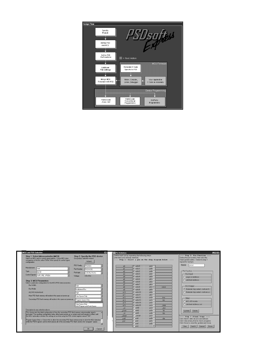
CIRCUIT CELLAR
®
Issue 120 July 2000
83
www.circuitcellar.com
16-bit architecture and familiar
programming environment.
Also, many of the newer con-
troller chips such as Hitachi SH
and Motorola M-Core, though
32-bits inside, retain 16-bit bus
options as a cost-saving alterna-
tive for designers.
Not so apparent but likely
candidates for ’4k design are the
16-bit DSPs that are still popu-
lar in volume applications such
as answering machines, mo-
dems, motor control, and so on.
Notably, unlike microcontrol-
lers, DSPs are starting to inte-
grate flash memory on-chip, so
an external chip is typically the
call. Most DSPs that integrate
memory use SRAM that has to
be loaded from nonvolatile memory.
Jan Gray’s “RISC-in-an-FPGA”
series from earlier this year (Circuit
Cellar
116-118) got me thinking how
cool it would be to pair his design with
a ’4k PSD. That would be a neat two-
chip setup, with FPGA, PLD, SRAM,
and flash memory bringing new mean-
ing to the term programmable.
The PSD accommodates all the
MCU variations with a few control
lines that take on varied duties, as
shown in Table 2. Note that this is a
partial list, and thanks to the myriad
of built-in options and PLDs, the PSD
should be able to hook up to just
about any controller you choose.
EXPRESSION SESSION
Thanks to the new chip features,
seasoned development software, and
aggressive marketing, working with
today’s PSD is quicker, easier, and
cheaper than ever.
At the time I wrote this article, I
didn’t have time to evaluate the ’4k
version of the tools, but I’m told the
16-bit version is similar to the exist-
ing DK900 kit (see Photo 1) that sup-
ports the current PSD9xxx 8-bit flash
memory parts. At $99, the DK900 is a
bargain; it includes a programmer,
evaluation board, the PSD Express
development software, as well as all
the bits and pieces (cables, power
supply, etc.).
You can download the software for
free from the Waferscale web site. That
will give you a chance to check it out
ahead of time. If the PSD looks like it
might be a good fit for your applica-
tion, the design kit is a great way for
you to take the next step and program
the parts to see them in action.
The opening screenshot of
PSD Express (see Photo 2)
provides an overview of the
steps involved in configuring
and programming a PSD. Start
the PSD development process
by specifying key parameters,
such as which MCU and PSD
you plan to use and the details
of the bus interface (see Photo
3a) and I/O pins (see Photo 3b).
After all is specified, PSD
Express handles the hairy de-
tails including generating the
PLD equations (see Photo 4a)
and C-driver software (see
Photo 4b) for basic functions
such as program, sector erase,
block erase, and so on. Finally,
merge the generated setup and
driver code with your application
software to create one hex file ready
for programming into the PSD.
The modern version of PSD Express
is much better than the ’93 software,
which required the user to handle a
lot of the drudgery. Now, it does prac-
tically everything except write your
application software for you, which is
just as well because then you’d be out
of a job!
MEMORY MUSINGS
Given the technology and market
situation at the time, designing in a
PSD in 1993 was considered bleeding-
edge. But with today’s bigger micros
and bloated C code, it’s probably a
better bet. Thanks to the march of
memory, the PSD sweet spot between
single-chip solutions and commodity
bulk memory has grown.
a)
b)
Photo 3a
—In
PSD Configuration
screens with
PSDSoft Express,
configuring the
various PSD
features and
options is a point -
and-click affair.
b—Here, pin PB4
is being defined as
an active high chip
select output.
Photo 2
—PSD development is basically a three-step process—configure
the PSD, cobble together a hex file, and program the part.

84
Issue 120 July 2000
CIRCUIT CELLAR
®
www.circuitcellar.com
Problem 4
—The master clock on a GPS satellite is
set to 10,229,999.99545 Hz. Why such an “odd”
value?
Problem 3
—It is often said that
a Triac is equivalent to two SCRs
wired back-to-back. However,
there is a difference that is
sometimes important. What is it?
Problem 2
—Using an ANSI C compiler, what does
the following code print, and why?
#include <stdio.h>
void main (void) {
int x=2, y=4, z;
z = x+++y;
printf (%d %d %d\n, x, y, z);
}
Tom Cantrell has been
working on chip, board,
and systems design and
marketing in Silicon Val-
ley for several years. You
may reach him by e-mail
at tom.cantrell@circuit
cellar.com or by telephone
at (510) 657-0264.
SOURCES
Programmable System Devices
Waferscale, Inc.
(510) 656-5400
Fax: (510) 657-8495
www.waferscale.com
ST Microelectronics
(256) 895-9544
Fax: (256) 895-9114
www.st.com
Historically, designing in a non-
commodity part was considered risky.
Every veteran of the IC age has a story
about the time their sole-source
turned the screws, whether on pur-
pose (i.e., greed) or otherwise (i.e., fab
burned down).
Although folks seem less adverse
to designing in proprietary parts, it’s
comforting to know that Waferscale
arranged alternate sourcing for the
PSD with Euro-powerhouse ST Micro-
electronics. Ironically, I heard that
lately it’s the commodity flash memo-
ries that are on allocation, not PSDs.
Where might the PSD go from
here? Naturally you can expect to see
them getting bigger, wider, and faster.
Also, it’s not difficult to imagine
evolving the programmable logic por-
tion beyond simple address decoding
and into the complexity range of
Photo 4a
—After the pin functions are defined, PSD Express generates the corresponding PLD equations automatically. b—PSD
Express also generates driver software in C for basic operations such as writing and erasing the flash memory.
a)
b)
standalone PLDs. Why not
throw in some other handy
stuff like a supervisor,
clock generator, real-time
clock, or UART?
The bottom line is, the
PSD fun has just begun!
I
Problem 1
—Consider a current transformer
that is used to measure the current in a 20-A
load at 120 V, 60 Hz. The turns ratio of the
transformer is 100, which is meant to generate
a 200 mA current in the secondary at full load,
which in turn generates a 2-V signal across a
10-
Ω
load. The transformer has an inductance
of 10 µH on the primary side when the second-
ary is open. How much voltage is generated
across the secondary if the 10-
Ω
load resistor
is accidentally omitted?
a) 0 V
b) 7.5 V
c) 750 V
d) infinite voltage
CIRCUIT CELLAR
Test Your EQ
CIRCUIT CELLAR
What’s
your EQ?
—The answers and 4
additional questions and answers are
posted at www.circuitcellar.com.
You may contact the quizmasters
at eq@circuitcellar.com.
8
more EQ
questions
each month in
Circuit Cellar Online
see pg. 2

CIRCUIT CELLAR
®
Issue 120 July 2000
95
www.circuitcellar.com
Page
19
Abacom Technologies
91
Ability Systems Corp.
91
Acroname Inc.
94
ActiveWire, Inc.
64
ADAC
63,79
Advanced Transdata Corp.
69
All Electronics
43
Amazon Electronics
92
Andrew Technologies, Inc.
94
Andromeda Research
94
AP Circuits
86
Arrick Robotics
59
Avocet Systems
40
Axiom Manufacturing
94
Bagotronix, Inc.
88
Beige Bag Software
93
Borge Instruments Ltd.
47
CAD-UL
91
CCS (Custom Computer Services)
31,90
Ceibo
92
Cermetek Microelectronics, Inc.
91
ChipTools, Inc.
94
Conitec
37,93
Connecticut microComputer, Inc.
92
Copeland Electronics, Inc.
86
Creative Control Concepts
88
Crystalfontz America, Inc.
17
Dallas Semiconductor
ADVERTISER
S
INDEX
9
Link Instruments
93
Lynxmotion, Inc.
88
Matrix Orbital Corp.
93
MCC (Micro Computer Control)
85
MetaLink Corp.
93
microEngineering Labs, Inc.
89
Microcoders
87
Micro Digital Inc.
74,81
Micromint, Inc.
18
Midwest Micro-Tek
89
MJS Consulting
92
Mosaic Industries, Inc.
33
NetBurner
90
NetMedia Inc.
85
Nohau Corp.
44
On Time
91
Ontrak Control Systems Inc.
C2
Parallax
94
PCB Express, Inc.
90
Peter H. Andreson
91
Phoenix International Corp.
89
Phytec
89
Phyton
94
Picofab, Inc.
93
Prairie Digital, Inc.
88
Pulsar, Inc.
32
Rabbit Semiconductor
57
Remote Processing
Page
Page
The Advertiser’s Index with links to their web sites is located at www.circuitcellar.com under the current issue.
88
RLC Enterprises, Inc.
93
RMV Electronics, Inc.
13,80
Saelig Co.
53
Scott Edwards Electronics, Inc.
91
Senix Corp.
85
Signum Systems
92
Sirius microSystems
88
SMTH Circuits
92
Software InnoVations
8
Solutions Cubed
85
Square 1 Electronics
89
Tal Technologies
90
Tabo Software Inc.
42,57
Technologic Systems
94
Technological Arts
C3,71
TechTools
87
Tern, Inc.
53
Trilogy Design
87
Two Technologies, Inc.
86
Vesta Technology
90
Vetra Systems Corp.
87
Virtual Tools, Inc.
37
Weeder Technologies
1
Wilke Technology GmbH
89
Z-World
93
Zanthic Technologies Inc.
25
ZiLOG
Page
Anatomy of a Compiler—A Retargetable ANSI-C Compiler
Who Needs Hardware?—Developing and Debugging without the Target Hardware
Simplify Your Software Testing—Linked Data Structures
Working with Leftovers—Designing a Frequency Meter
I
MicroSeries: The Joys of Writing Software—Part 1: Development
I
From the Bench: DFPs: Getting a Little Deeper
I
Silicon Update: We Ride the Wave—Trading Wires for Waves
EPC
Real-Time PC: Real-Time Executive for Multiprocessor Systems
Part 4: Debugging
EPC
Applied PCs: Embedded in a Kiosk?
Embedded Programming
PREVIEW
121
C4
Dataman Programmers, Inc.
94
Decade Engineering
87
Designtech Engineering Co.
4,5
DreamTech Computers
18
ECD (Electronic Controls Design)
52
Earth Computer Technologies
86
EE Tools (Electronic Engineering Tools)
85
ELNEC
42
EMAC Inc.
92
Embedded Micro Software
26
Embedded Internet Workshop
50
emWare
18
Engineering Express
86
FDI (Future Designs, Inc.)
91
General Device Instruments
26
General Software
86
Hagstrom Electronics
89
IMAGEcraft
43
IndustroLogic, Inc.
90,92
Intec Automation, Inc.
58
Interactive Image Technologies, Ltd.
86
Intronics, Inc.
82
Jameco
65,87
JK microsystems
43
JR Kerr Automation Engineering
90
J-Works, Inc.
92
Kustem Data Services, Inc.
7
Lemos International

96
Issue 120 July 2000
CIRCUIT CELLAR
®
www.circuitcellar.com
PRIORITY
INTERRUPT
steve.ciarcia@circuitcellar.com
I Call it “Prospecting”
esign contests have always been a big deal at
Circuit Cellar. There really is a difference in the
way we do them. Most magazines, especially the trades, treat contests simply as another
advertising contract with the sponsor. Rarely do they provide more than minimal management and
contestant entries usually involve describing design ideas rather than physically building a project. In truth,
when the objective of the contest is to promote the sponsor’s name and get designers to look at a new
product, there is no better way than saying, “Here’s a $50,000 car. All you have to do is describe how you’d
use an XYZ A/D converter!” Simple, sweet, and direct, but not our cup of tea.
We approach contests differently. I look at design contests as an incentive bonus plan for potential
Circuit
Cellar authors. Design contests are a “prospecting” venture, not an advertising contract coup.
Every project entered is looked at by our editorial staff and evaluated for its publishing value (within the IP
limits you grant us, of course). If you win, we’ll note that when your article is published, but winning isn’t
critical. Getting published in
Circuit Cellar is based on the application value of your project, not how it
compares to the competition. If it’s good, we want it, period.
Being a winner in a
Circuit Cellar contest, however, can be beneficial for your career. Companies seeking
good designers view our contests as an accurate test of your credentials and ability to finish what you start.
More than a few entrants have received job offers as the result of entering a
Circuit Cellar design contest.
Finally, besides being the ultimate resume builder, some contestants have reported that winning provided
the incentive they needed to launch their own business or product. With free publicity, the contest entry often
is the first product. Basically, winning in a
Circuit Cellar contest is a confidence builder.
So what am I leading up to? Well, how about climbing the hill one more time?
Soon we’ll announce the winners of our Microchip PIC2000 contest. The Philips Design2K contest just
ended and the projects are still in the judge’s hands. But, don’t unplug your soldering irons yet. On August 1,
our Zilog Driven to Design contest starts for all you Z180 fans. And, if we haven’t hit your favorite processor
yet, just wait a minute, we’ll get to it eventually. Atmel steps up to the plate as a sponsor in early 2001. With
all of these contests in the pipe, subscribers can count on many terrific project articles covering a variety of
great processors in the issues to come.
Of course, we continue tuning the process. With each successive contest, we try to make it easier for you
to enter. One criticism we occasionally hear is, “I can’t get the part.” Or, “the distributor has a $75 minimum
order.” The reason is straightforward if you understand semiconductor companies. Contests are expensive!
Usually the company group with the marketing money to afford a contest is the same group responsible for
the latest and greatest chip. Unfortunately, it’s often the most difficult component to find, too.
I’ve been fairly successful convincing companies to broaden the spectrum to include tried and true chips
along with the hot new stuff. That’s one reason our Zilog Driven to Design contest includes the whole Z180-
series and not just the Z183 (the new guy). To facilitate even more entries, I added another provision to our
contest agreements. If the sponsor supplies us with sample components (which is in the company’s best
interest considering the cost of sponsoring a contest), I’ll pay to ship parts to contestants anywhere. I don’t
want a simple problem like not being able to find the key component in Beijing to stop you from entering.
Perhaps it’s because we’re so serious about making contests good for both readers and sponsors, that
there’s a waiting list for
Circuit Cellar contests. Companies are putting money on the table to reserve space
for 2002 already. As a
Circuit Cellar reader, you don’t have to worry. We’ll make it a good one!
d
Wyszukiwarka
Podobne podstrony:
circuit cellar2001 07
circuit cellar1995 07
circuit cellar2002 07
circuit cellar1993 07
circuit cellar1994 07
circuit cellar1996 07
circuit cellar1997 07
circuit cellar2004 07
circuit cellar1994 07
circuit cellar2004 07
circuit cellar1996 07
circuit cellar1995 07
circuit cellar1997 07
circuit cellar1993 07
więcej podobnych podstron