
November 1998
Process Industry Practices
Page 1 of 29
SAMPLE
NOT FOR
Process Industry Practices
P&ID
PIP PIC001
Piping and Instrumentation
Diagram Documentation Criteria
Table of Contents
1. Introduction .................................. 4
2. References ................................... 4
2.1 Process Industry Practices (PIP) ......... 4
2.2 Industry Codes and Standards ............ 5
2.3 Government Regulations ..................... 5
3. Definitions .................................... 5
4. Requirements............................... 6
4.1 General ................................................ 6
4.2 Format ................................................. 6
4.3 EquipmentError! Bookmark not defined.
4.4 Piping ................................................. 10
4.5 Instrumentation & ControlsError! Bookmark not defined
Appendices .................................... 12
Appendix A – Tables & Symbols
Appendix B – Cover Sheets
Appendix C – Example P&IDs
Selected Pages
(Example of Information
contained in Practice)

PURPOSE AND USE OF PROCESS INDUSTRY PRACTICES
In an effort to minimize the cost of process industry facilities, this Practice has
been prepared from the technical requirements in the existing standards of major
industrial users, contractors, or standards organizations. By harmonizing these
technical requirements into a single set of Practices, administrative, application, and
engineering costs to both the purchaser and the manufacturer should be reduced. While
this Practice is expected to incorporate the majority of requirements of most users,
individual applications may involve requirements that will be appended to and take
precedence over this Practice. Determinations concerning fitness for purpose and
particular matters or application of the Practice to particular project or engineering
situations should not be made solely on information contained in these materials. The
use of trade names from time to time should not be viewed as an expression of
preference but rather recognized as normal usage in the trade. Other brands having the
same specifications are equally correct and may be substituted for those named. All
Practices or guidelines are intended to be consistent with applicable laws and
regulations including OSHA requirements. To the extent these Practices or guidelines
should conflict with OSHA or other applicable laws or regulations, such laws or
regulations must be followed. Consult an appropriate professional before applying or
acting on any material contained in or suggested by the Practice.
This Practice is subject to revision at any time by the responsible Function Team
and will be reviewed every 5 years. This Practice will be revised, reaffirmed, or
withdrawn. Information on whether this Practice has been revised may be found at
http://www.pipdocs.org.
© Process Industry Practices (PIP), Construction Industry Institute, The
University of Texas at Austin, 3208 Red River Street, Suite 300, Austin,
Texas 78705. PIP member companies and subscribers may copy this Practice
for their internal use.
Note (added August 2000): PIP PIC001, Piping and Instrumentation Diagram Documentation
Criteria, incorporates symbols previously published in standards owned and copyrighted by
Instrument Society of America (ISA). These are printed with agreement from ISA.
Not printed with State funds

November 1998
PIP PIC001
Piping and Instrumentation Diagram Documentation Criteria
Process Industry Practices
Page 4 of 29
SAMPLE
NOT FOR
COMMERCIAL USE
1.
Introduction
1.1
Purpose
This Practice provides criteria for the development of Piping and Instrumentation
Diagrams (P&IDs).
1.2
Scope
This Practice addresses the format and content shown on a P&ID. The Practice is
independent of time in a facility life cycle and encompasses design, construction,
operations and maintenance.
This Practice covers the generation of new P&IDs and does not apply to the revision
of existing P&IDs. It also applies to P&IDs provided by packaged equipment
vendors.
A P&ID is a detailed graphical representation of a process including the hardware
and software (e.g., piping, equipment, instrumentation) necessary to design, construct
and operate the facility. Common synonyms for P&IDs include EFDs (Engineering
Flow Diagrams), UFDs (Utility Flow Diagrams) and MFDs (Mechanical Flow
Diagrams). This Practice applies to all diagrams that fit the definition of a P&ID.
The criteria presented in this Practice can be applied to whichever CAD system is
employed for developing the P&IDs and are not vendor, hardware or software
specific.
The example P&IDs included in the Appendices are not intended to recommend
specific design details or requirements. Example P&IDs are included to provide an
illustration of how the elements of the recommended Practice are combined into a
P&ID.
2.
References
Applicable requirements in the latest edition (or the edition indicated) of the following
industry standards and Process Industry Practices shall be considered an integral part of this
Practice. Short titles will be used herein when appropriate.
2.1
Process Industry Practices (PIP)
–
PIP INEG1000 - Insulation Design and Type Codes
–
PIP PCCIP001 - Instrument Piping and Tubing Systems Criteria
–
PIP PCCPS001 - Instrument and Control Systems Criteria for Packaged
Equipment
–
PIP PCEDO001 - Guidelines for Control Systems Documentation
–
PIP PCSIP001 - Instrument Piping and Tubing Systems Specifications
–
PIP PNE00001 - Design of ASME B31.3 Metallic Piping Systems
–
PIP PNSM0001 - Piping Line Class Designator System

November 1998
PIP PIC001
Piping and Instrumentation Diagram Documentation Criteria
Process Industry Practices
Page 5 of 29
SAMPLE
NOT FOR
COMMERCIAL USE
2.2
Industry Codes and Standards
•
American National Standards Institute (ANSI)
–
ANSI/FCI 70-2-1991 - Quality Control Standard for Control Valve Seat
Leakage
•
American Society of Mechanical Engineers (ASME)
–
ASME Boiler and Pressure Vessel Code
Section VIII - Pressure Vessels
•
ISA
–
ISA S5.1 - Instrumentation Symbols and Identification (R1992)
–
ISA S5.2 - Binary Logic Diagrams for Process Operations (R1981)
–
ISA S5.3 - Graphic Symbols for Distributed Control / Shared Display
Instrumentation, Logic and Computer Systems
–
ISA S84.01 - Application of Safety Instrumented Systems for the Process
Industries
–
ISA S91.01 - Identification of Emergency Shutdown Systems and Controls
That Are Critical to Maintaining Safety in Process Industries
•
Tubular Exchanger Manufacturers Association (TEMA)
–
TEMA Standards
2.3
Government Regulations
•
Occupational Safety and Health Administration (OSHA)
–
OSHA 29 CFR 1910.119 - Occupational Safety and Health Standards,
Process Safety Management of Highly Hazardous Chemicals
3.
Definitions
For the purposes of this Practice, the following definitions apply:
Accessible: A term applied to a device or function that can be used or be seen by an operator
for the purpose of performing control actions (e.g., set point changes, auto-manual transfer or
on-off actions) (Reference ISA S5.1.)
Automated Valve: Any valve with a locally or remotely controlled actuator. Examples are
throttling control valves and on/off block valves. Actuators are typically air-operated
(diaphragm or piston), electric or hydraulic, some with spring return function. Manually-
operated valves are sometimes also tagged as automated valves such as when a manual valve
is fitted with position switches.
Auxiliary P&ID: P&ID used to show details in order to unclutter other P&IDs (e.g., lube oil
system, sample systems, instrument details)
Basic Process Control System (BPCS): The Basic Process Control System is the control
equipment and system that is installed to regulate normal production functions. The BPCS
may contain combinations of single loop pneumatic controllers, single loop electronic

November 1998
PIP PIC001
Piping and Instrumentation Diagram Documentation Criteria
Process Industry Practices
Page 6 of 29
SAMPLE
NOT FOR
COMMERCIAL USE
4.
Requirements
Practice requirements are divided into five sections (General, Format, Equipment, Piping and
Instruments & Controls). Reference the appropriate section for the specific area of interest.
4.1
General
Practice requirements are intended to provide a balance between the desire to show
all data on P&IDs with the need to make P&IDs legible and easy to read. Most
details that are available from other types of documentation (e.g., instrument loop
diagrams, vessel data sheets) are not recommended for inclusion on P&IDs.
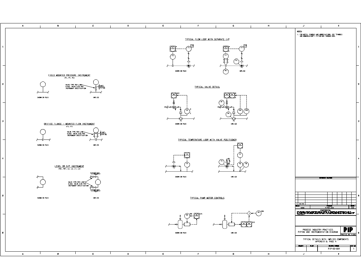
This Practice utilizes the concepts of typical details with implied components
whenever appropriate to simplify P&IDs. See the cover sheet in Appendix B Page 4
for examples. Additional examples may be added as required.
4.2
Format
4.2.1
Layout
4.2.1.1
Criteria contained herein apply to reading a P&ID from the bottom
or right side of the drawing. The top of a horizontal line and the
left side of a vertical line is the top of a pipe. The bottom of a
horizontal line and the right side of a vertical line is the bottom of
a pipe. Use a note to clarify as required.
4.2.1.2
Drawing size is 22" x 34" (560 mm x 864 mm).
4.2.1.3
Layout each P&ID to avoid clutter and allow future modifications.
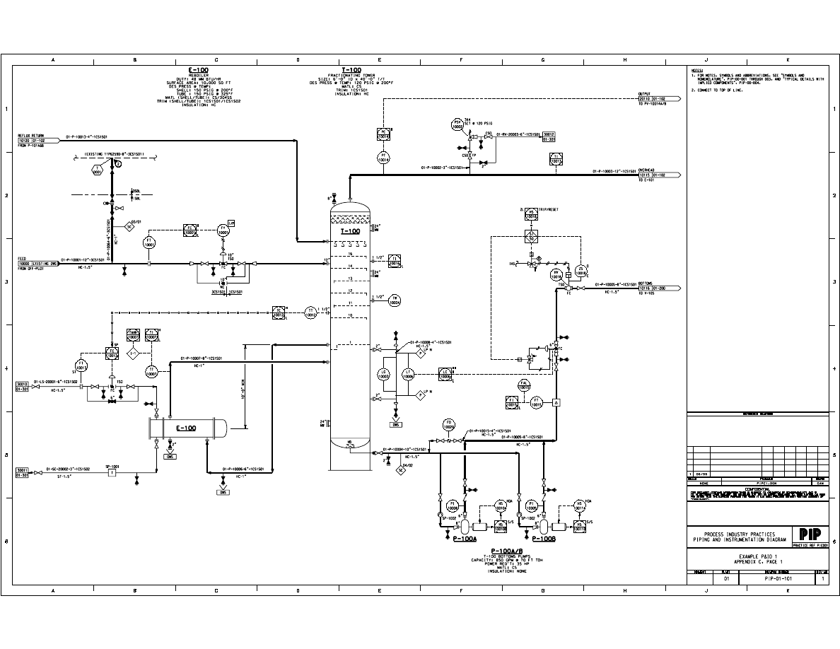
Show no more that three pieces of major equipment per P&ID. A
set of pumps in the same service is one piece of equipment for the
purpose of P&ID layout per Appendix C Page 1.
4.2.1.4
Show primary flow on each P&ID from left to right.
Show flow through equipment relative to actual arrangement (e.g.,
cooling water supply in bottom of exchanger tube bundle and
cooling water return out top).
4.2.1.5
Show primary process lines heavier than secondary and utility
lines as described in Section 4.2.3.
4.2.1.6
Show off-page connector arrows for primary, secondary and
instrumentation lines entering the P&ID horizontally 0.25"
(6.4 mm) from the left inside borderline and exiting 0.25"
(6.4 mm) horizontally from the right inside borderline per
Appendix C Page 1.
Utility connectors may be shown at any convenient location on the
body of the P&ID.

November 1998
PIP PIC001
Piping and Instrumentation Diagram Documentation Criteria
Process Industry Practices
Page 7 of 29
SAMPLE
NOT FOR
COMMERCIAL USE
4.2.1.16 Show the center point of a PSE (Pressure Safety Element)
identification bubble 0.5" (12.7 mm) above a horizontal line or left
of a vertical line and 0.5" (12.7 mm) away from the rupture disc or
equipment.
4.2.2
Symbology
4.2.2.1
Show format, equipment, piping and instrument symbols per
Appendices A-1, A-2, A-3 and A-4.
Show equipment internals using a short dash/space line at a weight
of 0.02" (0.5 mm).
Show a mating piping flange to an equipment nozzle at a distance
of 0.06" (1.5 mm).
Show a connection to an equipment nozzle when the connection is
welded per Appendix A-3 Page 6.
4.2.2.2
Show a note reference symbol per Appendix A-1 Page 2 at a
weight of 0.03" (0.8 mm).
Show a note number in the symbol at a weight of 0.02" (0.5 mm).
4.2.2.3
Show normally closed manual valves using a darkened solid
symbol.
When darkened in valves cannot be used because of symbol type
(e.g., butterfly valve), use the abbreviation for Normally Closed
(NC) directly below the valve in a horizontal line or to the right of
the valve in a vertical line.
Show on-off valves in normal operating position.
Do not show control valves or relief valves normally closed.
4.2.3
Lines
4.2.3.1
Show primary process lines per Appendix A-3 Page 3 at a weight
of 0.06" (1.5 mm).
4.2.3.2
Show secondary, utility, future or existing lines per Appendix A-3
Page 3 at a weight of 0.02" (0.5 mm).
4.2.3.3
Show instrument line symbols per Appendix A-4 Page 4 at a
weight of 0.01" (0.3 mm).
4.2.3.4
Show packaged equipment limit lines per Appendix A-1 Page 2 at
a weight of 0.03" (0.8 mm).
4.2.3.5
Show line class and insulation breaks per Appendix A-1 Page 2 at
a weight of 0.02" (0.5 mm).
4.2.3.6
Minimize “dog legged” lines.
4.2.3.7
Maintain a minimum of 0.5" (12.7 mm) spacing between lines.
4.2.3.8
Show flow arrows at corners and intersecting lines, where there is
a change in direction of majority of flow.

November 1998
PIP PIC001
Piping and Instrumentation Diagram Documentation Criteria
Process Industry Practices
Page 8 of 29
SAMPLE
NOT FOR
COMMERCIAL USE
4.3.1.5
Show Equipment Item Number and Title/Service as a minimum.
Reference Section 4.3.13 for a complete list of equipment data for
all equipment addressed in this Practice. For equipment not
covered in this Practice, show equipment data as necessary.
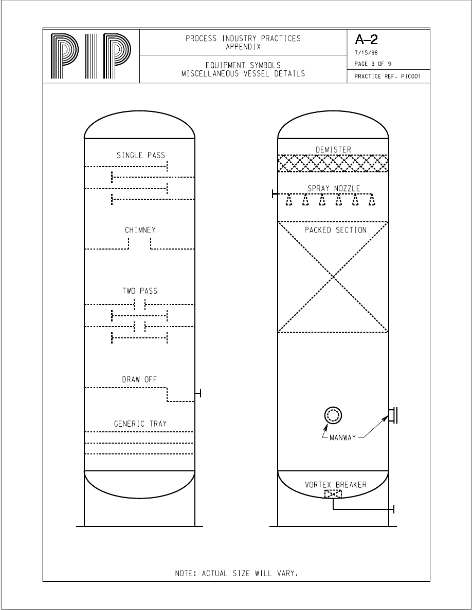
4.3.1.6
Show internals for equipment as dashed lines as described in
Section 4.2.2.1. Omit details of internals that have no significant
bearing on the piping design and layout or equipment operation.
4.3.1.7
Do not show equipment elevations unless they are necessary to
specify process requirements for associated equipment location or
orientation relative to one another.
4.3.1.8
Show associated trim (e.g., vent and drain valves, instrument
bridles) for equipment.
4.3.1.9
Show auxiliary system requirements for individual pieces of
equipment (e.g., lube oil systems, seal flush systems, turbine gland
leak-off piping, sample systems) on auxiliary P&IDs.
4.3.1.10 Show jacketing requirements for equipment.
4.3.1.11 Show the type of insulation (e.g., personnel protection, heat
conservation) for equipment as part of the equipment data. Show
insulation thickness where applicable.
4.3.2
Agitators
4.3.2.1
The term agitator applies to mechanical mixers and aerators.
4.3.2.2
Show agitators per Appendix A-2 Page 3.
4.3.3
Blowers
4.3.3.1
Show blower symbols as centrifugal or positive displacement as
required.
4.3.3.2
Show blowers per Appendix A-2 Page 2.
4.3.4
Compressors
4.3.4.1
Show the compressor symbol for each stage of multistage
compressors. Multi-staged compressors may be shown on multiple
P&IDs.
4.3.4.2
Show compressors per Appendix A-2 Page 2.
4.3.5
Drivers
4.3.5.1
Show drivers with driven equipment using the symbols for motors,
diesel engines and turbines. Equipment numbers for drivers are
normally not required since equipment data for the drivers is
shown as an integral part of the associated driven component.
Show equipment number for driver if it drives more than one piece
of equipment or if the driver number is different from the
equipment it drives.

November 1998
PIP PIC001
Piping and Instrumentation Diagram Documentation Criteria
Process Industry Practices
Page 9 of 29
SAMPLE
NOT FOR
COMMERCIAL USE
4.3.12 Classification of Equipment
The equipment classifications listed below are used on the example P&IDs
contained in the Appendices for illustrative purposes only. These equipment
classifications are only one example of classifications allowed by this
Practice.
CLASS
SUBJECT
DESCRIPTION
A
Mixing Equipment
Agitators, Aerators, Mechanical Mixers
B
Blowers
Centrifugal Blowers, Positive Displacement
Blowers, Fans
C
Compressors
Centrifugal, Reciprocating, Screw, Vacuum
D
Mechanical Drivers
Electric and Pneumatic Motors, Diesel Engines,
Steam and Gas Turbines
E
Heat Exchangers
Unfired Heat Exchangers, Condensers,
Coolers, Reboilers, Vaporizers and Heating
Coils, Double Pipe, Spiral, Plate & Frame, Air
Coolers
F
Furnaces
Fired Heaters, Furnaces, Boilers, Kilns
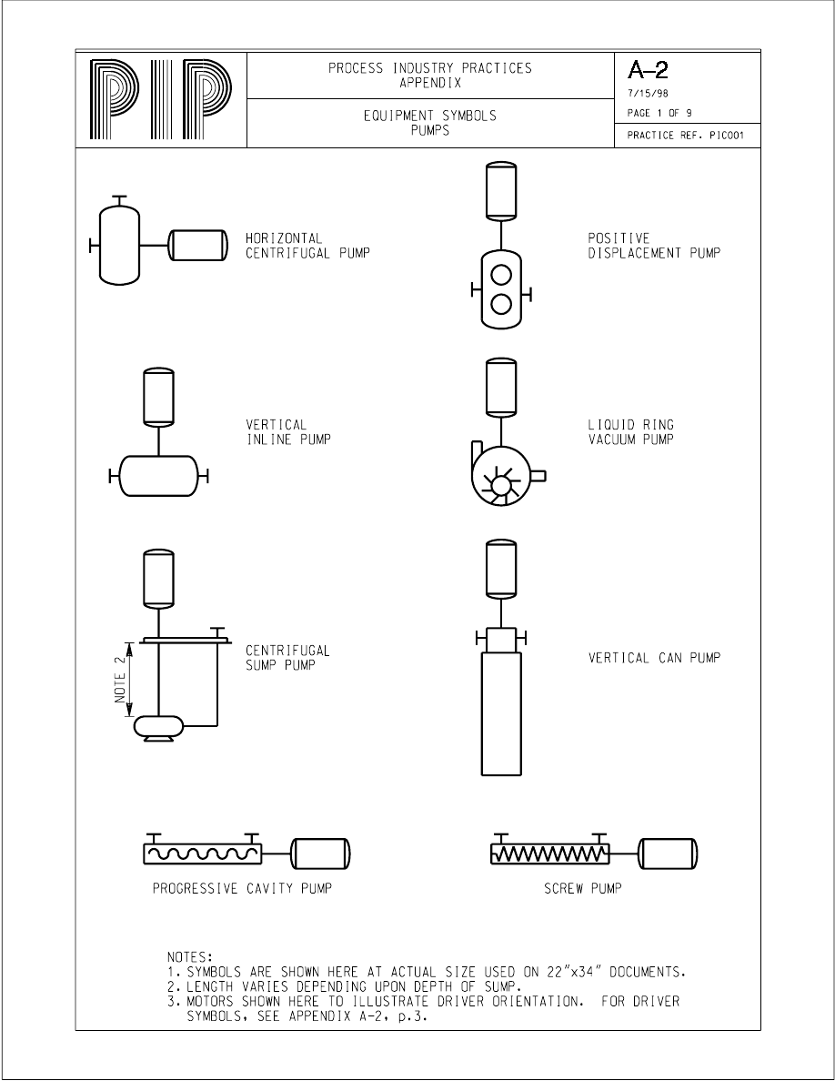
P
Pumps
Horizontal and Vertical Centrifugal, Positive
Displacement, Vertical Canned, Screw, Gear,
Sump
R
Reactors
T
Towers / Columns
TK
Tanks
API atmospheric and low pressure
U
Miscellaneous
Equipment
Filters, Bins, Silos
V
Drums
Separators, Driers, Accumulators
4.3.13 Equipment Data
This section lists the data to be shown on the P&ID for types of equipment.
Show this information on the P&ID in relation to the appropriate equipment
symbol per Section 4.2.4.5. Show units of measure (e.g., GPM, PSIG,
BTU/hr) for equipment data as required. Equipment not listed should be
described as appropriate to convey important data.
4.3.13.1 Agitators, Mixers
•
Equipment/Item Number
•
Title/Service
•
Power Requirements
•
Materials of Construction

November 1998
PIP PIC001
Piping and Instrumentation Diagram Documentation Criteria
Process Industry Practices
Page 10 of 29
SAMPLE
NOT FOR
COMMERCIAL USE
4.3.13.7 Vessels/Tanks
•
Equipment/Item Number
•
Title/Service
•
Size, Capacity
•
Design Pressure @ Temperature
•
Materials of Construction
•
Trim
•
Insulation
4.4
Piping
4.4.1
Line Data Identification
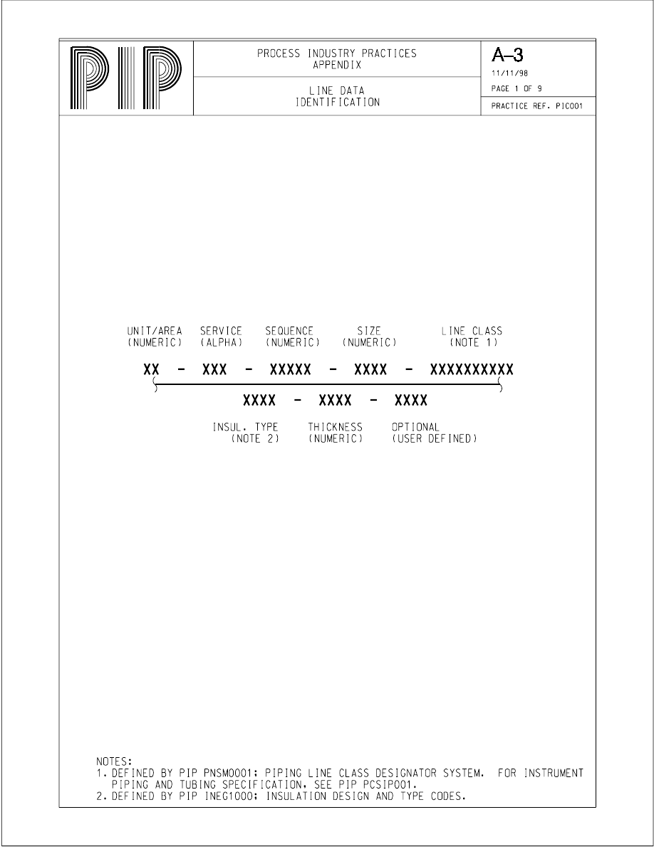
4.4.1.1
Show the line data identification per Appendix A-3 Page 1.
Do not use suffixes as part of the sequence number.
Sequence numbers typically originate and terminate at equipment.
Assign different sequence numbers to line branches that terminate
at different equipment numbers or lines.
Do not change the sequence number when the line flows through a
piping specialty item or a control valve or when there is a line class
break.
Assign different sequence numbers to the inlet and outlet of
pressure relief valves.
4.4.1.2
The size and insulation thickness fields accommodate either
English or metric units.
Show insulation code changes using the point of change symbol
referenced in Appendix A-1 Page 2.
4.4.1.3
Show special layout requirements (e.g., No Pockets) with a note.
4.4.2
Line Service Codes
4.4.2.1
Line service codes are listed in Appendix A-3 Page 2. Additional
line service codes can be added as required.
4.4.2.2
Each line service code consists of one to three alpha characters.
4.4.3
Piping Line Symbols
4.4.3.1
Show piping for primary, secondary, utility, jacketed or double
containment, and future lines per Appendix A-3 Page 3.
4.4.3.2
Show piping for existing lines depicted on new P&IDs per
Appendix A-3 Page 3.
4.4.3.3
Piping for new lines depicted on existing P&IDs are not covered
by this Practice.

November 1998
PIP PIC001
Piping and Instrumentation Diagram Documentation Criteria
Process Industry Practices
Page 11 of 29
SAMPLE
NOT FOR
COMMERCIAL USE
4.5.4
Safety/Relief Devices
4.5.4.1
Show and tag relief devices and conservation vents per Appendix
A-4 Page 7 (e.g., PSE and PSV). Use optional explanatory text for
clarification of the type and function of the device (e.g.,
“Emergency Relief,” “Conservation Vent,” “Explosion Panel”)
located next to the tag. Reference Sections 4.2.1.15 and 4.2.1.16.
PSV typically refers to reclosing devices. PSE typically refers to
non-reclosing devices.
Use PSE only for safety related service. Use PCV or PCE for non-
safety conservation vents.
Comment: Per ISA S5.1 (Table 1, Note 8), “The designation
PSV applies to all valves intended to protect against emergency
pressure conditions regardless of whether the valve construction
and mode of operation place them in the category of the safety
valve, relief valve or safety relief valve.”
4.5.4.2
Show relief device set pressures.
4.5.4.3
Show the relief device size:
•
PSVs - inlet size and outlet size
•
Rupture discs - disc diameter
•
Conservation vents - inlet nozzle size if there is not a pipe
away or tail piece, otherwise show inlet size and outlet size
•
Explosion panels - surface area or dimensions
4.5.4.4
Show the orifice size letter designation for relief valves between
the inlet and outlet sizes (e.g., 3K4). Do not show the relief device
sizing basis or flow capacity.
4.5.4.5
Do not show the materials of construction for relief devices.
4.5.5
Equipment Start/Stops
4.5.5.1
Do not show the local start/stop hand switch for motors without
remote controls.
Show local (field) hand switches (bubble and tag) that:
•
Are part of an operator control panel
•
Interface with other systems (e.g., interlocks)
•
Otherwise need explanation
4.5.5.2
Show all control room (DCS or panel board) hand switches with
the appropriate bubble symbol and tag.
4.5.5.3
Label all hand switch positions or functions. Locate the labels
outside the bubble symbol, on the upper right, using the standard
text abbreviations shown in the Appendices. All others must be
spelled out.

November 1998
PIP PIC001
Piping and Instrumentation Diagram Documentation Criteria
Process Industry Practices
Page 12 of 29
SAMPLE
NOT FOR
COMMERCIAL USE
Appendices
The Appendices of this Practice contain tables of commonly used symbols, abbreviations and
other identifiers, as well as typical details and example P&IDs.
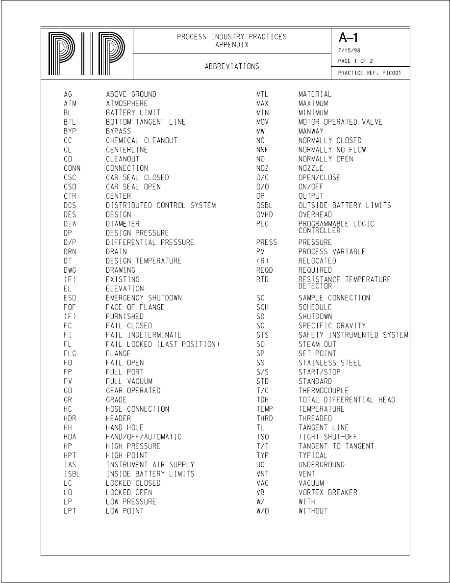
Appendix A contains symbols and text grouped by function. The symbols and text are shown
the same size as would be utilized for a standard full size (22" x 34") P&ID.
Appendix B contains the same data as Appendix A, organized into cover sheets. Cover sheets
are also commonly referred to as lead sheets or legend sheets.
Electronic native files for the text, symbols and cover sheets are available from PIP for input
to member’s CAD systems. Development of project specific cover sheets is recommended
using the PIP native files as a starting point. Additions and/or deletions are allowed to meet
requirements. Cover sheet borders and title blocks may be altered.
Appendix C contains example P&IDs that illustrate the text and utilize the symbols and
legends on the cover sheets.
Comment: The cover sheets and P&IDs are drawn as standard full size (22" x 34")
P&IDs, but reduced to standard PIP Practice 8 1/2" x 11" pages for electronic distribution
purposes. It is recommended that the cover sheets and P&IDs be printed on 11" x 17"
pages. This requires use of a PostScript printer driver.

SAMPLE
NOT FOR
COMMERCIAL USE
Appendix A – Tables & Symbols
A-1 Format Tables & Symbols
1. Abbreviations
2. Miscellaneous Symbols
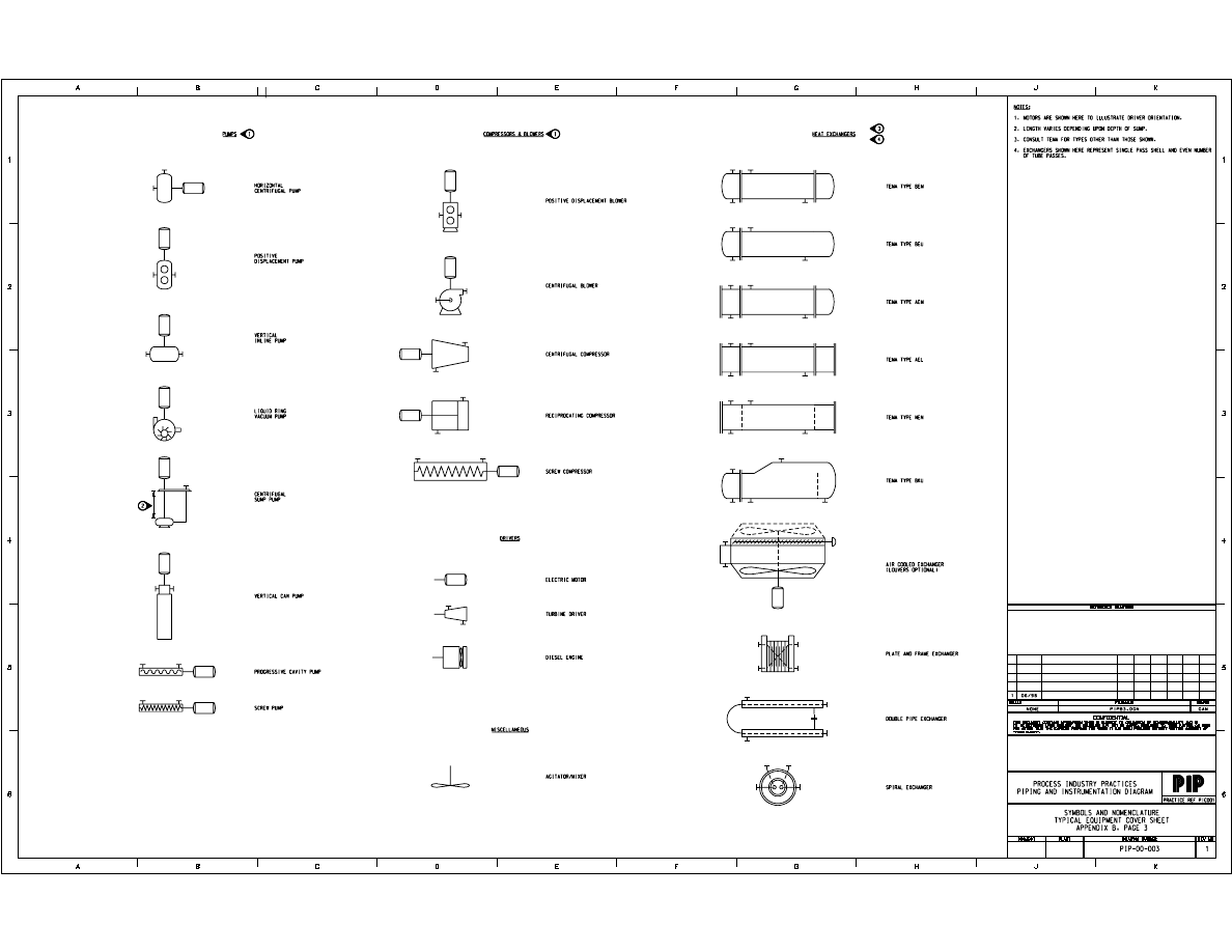
A-2 Equipment Tables & Symbols
1. Pumps
2. Compressors & Blowers
3. Drivers & Agitator/Mixer
4. TEMA Type Exchangers
5. Miscellaneous Exchangers
6. Storage Tanks
7. Storage Tanks
8. Storage Sphere and Furnace
9. Miscellaneous Vessel Details
A-3 Piping Tables & Symbols
1. Line Data Identification
2. Line Service Codes
3. Piping Line Symbols
4. Valve Symbols
5. Piping Specialty Items
6. Piping Fittings
7. Off-Page Connectors and Tie-In Symbol
8. Drain Connectors
9. Notes
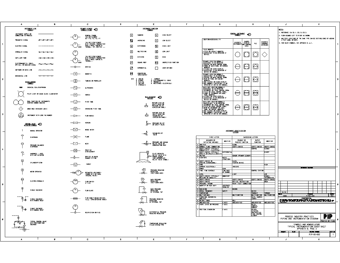
A-4 Instruments & Controls Tables & Symbols
1. Instrument Identification Letters
2. General Instrument Symbols
3. Instrument Function Symbols
4. Instrument Line Symbols
5. Primary Element Symbols (Flow)
6. Control Valve Actuator Symbols
7. Self-Actuated Devices
8. Miscellaneous Instrument Symbols.
SAMPLE
NOT FOR
COMMERCIAL USE
SAMPLE
NOT FOR
COMMERCIAL USE
SAMPLE
NOT FOR
COMMERCIAL USE
SAMPLE
NOT FOR
COMMERCIAL USE

SAMPLE
NOT FOR
COMMERCIAL USE
Appendix B – Cover Sheets
•
Symbols & Nomenclature - Typical Piping
•
Symbols & Nomenclature - Typical Instrumentation
•
Symbols & Nomenclature - Typical Equipment
•
Typical Details with Implied Components
SAMPLE
NOT FOR
COMMERCIAL USE
SAMPLE
NOT FOR
COMMERCIAL USE
SAMPLE
NOT FOR
COMMERCIAL USE


SAMPLE
NOT FOR
COMMERCIAL USE
Appendix C – Example P&IDs
1. Example P&ID 1
2. Example P&ID 2
3. Example Utility P&ID
SAMPLE
NOT FOR
COMMERCIAL USE
Wyszukiwarka
Podobne podstrony:
Schematy technologiczne1
przykład sprawozdania, Technologia chemiczna, Projekt technologiczny, Projekty, fwd pd , projekt tec
Schemat technologiczno aparaturowy
przykłady sprawozdań, Technologia+Chemiczna+7, Technologia Chemiczna
Metodologia badań z logiką dr Karyłowski wykład 13 Dodatkowe przykłady schematów quasiekspe
06 przykladowy schemat 1
przykład sprawozdania2, Technologia chemiczna, Projekt technologiczny, Projekty, fwd pd , projekt te
Przykłady zastosowań technologii RFID w magazynach, ABC Magazynu
przykładowy schemat rozwiązania zadania praktycznego projekt
PRZYKŁADOWY SCHEMAT INDYWIDUALNEGO PROGRAMU?UKACYJNEGO
Podstawy Technik Wytwarzania I Przykład procesu technologicznego toczenia wykonanego w programie GTJ
05 tworzenie schematow technologicznych
Projekt - przykład, 0, Karta technologiczna
Przykłady ośrodków technologii doc
Przykładowy schemat rozwiązywania zadań na BEP
przykłądowy schemat instrukcji bezpiecze poż
Przykładowy schemat rozwiązywania zadań na WACC
Załączniki 1i2 (schematy technologiczne)
Schemat technologiczny w�z�a wentylacja
więcej podobnych podstron