Document Number: 50049
For technical questions, contact: sfer@vishay.com
www.vishay.com
Revision: 16-Oct-08
1
LTO 30
Vishay Sfernice
30 W Power Resistor Thick Film Technology
LTO series are the extension of RTO types. We used the
direct ceramic mounting design (no metal tab) of our RCH
power resistors applied to semiconductor packages.
FEATURE
• 30 W at 25 °C case temperature heatsink
mounted
• Direct mounting ceramic on heatsink
• Broad resistance range: R010 to 550K
• Non inductive
• TO-220 package: Compact and easy to mount
• RoHS compliant
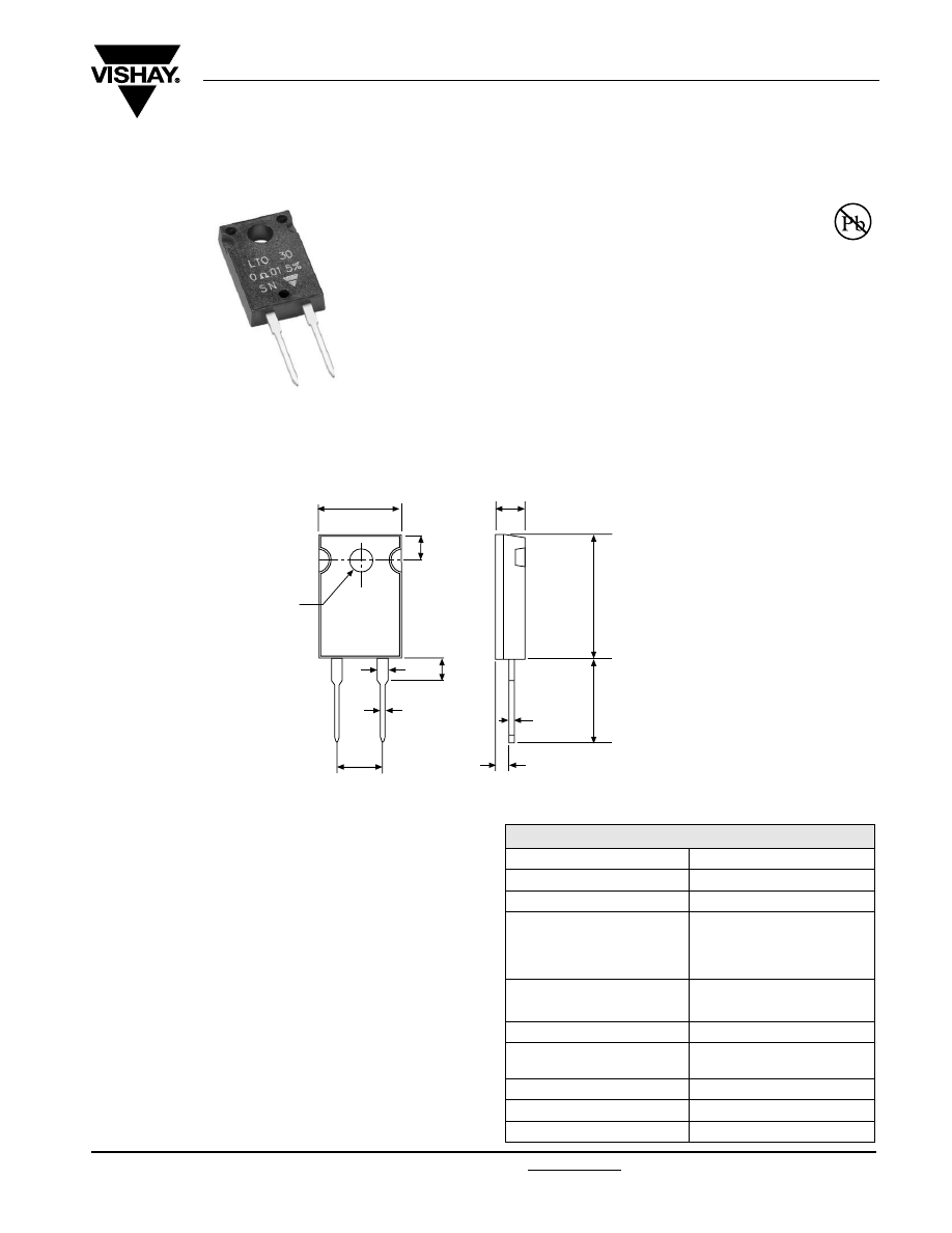
DIMENSIONS in millimeters
MECHANICAL SPECIFICATIONS
Mechanical Protection
Molded
Resistive Element Thick
film
Substrate Alumina
Connections
Tinned copper
Weight
2 g max.
Mounting Torqure
1 Nm
DIMENSIONS
Standard Package
TO-220 isolated case
ENVIRONMENTAL SPECIFICATIONS
Temperature Range
- 55 °C to + 155 °C
Climatic Category
55/155/56
Flammability
IEC 60695-11-5
2 applications 30 s
separated by 60 s
RoHS
COMPLIANT
• Tolerance unless otherwise specified: ± 0.3 mm
3.2
16.2
10.4
1.8
5.08
0.6
3.5
1.3
0.8
12.7
3.2
Ø 3.2
ELECTRICAL SPECIFICATIONS
Resistance Range
0.010
Ω to 550 kΩ
Tolerances (Standard)
± 1 % to ± 10 %
Dissipation and Associated
Onto a heatsink
Power Rating and
Thermal Resistance
of the Component
30 W at + 25 °C (case temp.)
R
TH
(j - c): 4.2 °C/W
Free air:
2.25 W at + 25 °C
Temperature Coefficient
See Performance table
Standard
± 150 ppm/°C
Limiting Element Voltage U
L
250 V
Dielectric Strength
MIL STD 202
1500 V
RMS
- 1 min
10 mA max.
Insulation Resistance
≥ 10
4
M
Ω
Inductance
≤
0.1 µH
Critical Resistance
2.08 k
Ω
www.vishay.com
For technical questions, contact: sfer@vishay.com
Document Number: 50049
2
Revision: 16-Oct-08
LTO 30
Vishay Sfernice
30 W Power Resistor Thick Film Technology
CHOICE OF THE HEATSINK
The user must choose according to the working conditions of the component (power, room temperature).
Maximum working temperature must not exceed 150 °C. The dissipated power is simply calculated by the following ratio:
P:
Expressed in W
ΔT:
Difference between maximum working temperature and room temperature
R
TH
(j - c): Thermal resistance value measured between resistive layer and outer side of the resistor. It is the thermal
resistance of the component.
R
TH
(c - a): Thermal resistance value measured between outer side of the resistor and room temperature. It is the thermal
resistance of the heatsink itself (type, shape) and the quality of the fastening device, and the thermal resistance
of the thermal compound.
Example:
R
TH
(c - a) for LTO 30 power rating 10 W at ambient temperature + 25 °C
Thermal resistance R
TH
(j - c): 4.2 °C/W
Considering equation (1) we have:
ΔT = 150 °C - 25 °C = 125 °C
R
TH
(j - c) + R
TH
(c - a) =
=
= 12.5 °C/W
R
TH
(c - a) = 12.5 °C/W - 4.2 °C/W = 8.3 °C/W
with a thermal grease R
TH
(c - h) = 1 °C/W, we need a heatsink with R
TH
(h - a) = 7.3 °C/W.
PERFORMANCE
TESTS
CONDITIONS
REQUIREMENTS
Momentary Overload
EN 60115-1
1.5 Pr/5 s
U
S
< 1.5
U
L
± (0.5 % + 0.005
Ω)
Rapid Temperature Change
EN 60115-1
IEC 60068-2-14 Tests Na
5 cycles
- 55 °C to + 155 °C
± (0.5 % + 0.005
Ω)
Load Life
EN 60115-1
1000 h Pr at + 25 °C
± (1 % + 0.005
Ω)
Humidity (Steady State)
MIL STD 202
Method 103 B Cond. D
± (0.5 % + 0.005
Ω)
Vibration
MIL STD 202
Method 204 Cond. D
± (0.2 % + 0.005
Ω)
Terminal Strength
MIL STD 202
Method 211 Cond. A1
± (0.2 % + 0.005
Ω)
Shock
100G, MIL STD 202
Method 213 Cond. I
± (0.5 % + 0.005
Ω)
SPECIAL FEATURES
Resistance Values
≥ 0.010
≥ 0.015
≥ 0.1
≥ 0.5
Tolerances
± 1 % at ± 10 %
Typical Temperature Coefficient
(- 55 ° to + 155 °C)
± 900 ppm/°C
± 700 ppm/°C
± 250 ppm/°C
± 150 ppm/°C
P
ΔT
R
TH
j
c
–
(
) R
TH
c
a
–
(
)
+
[
]
----------------------------------------------------------------------
1
( )
=
ΔT
P
-------
125
10
----------
Document Number: 50049
For technical questions, contact: sfer@vishay.com
www.vishay.com
Revision: 16-Oct-08
3
LTO 30
30 W Power Resistor Thick Film Technology
Vishay Sfernice
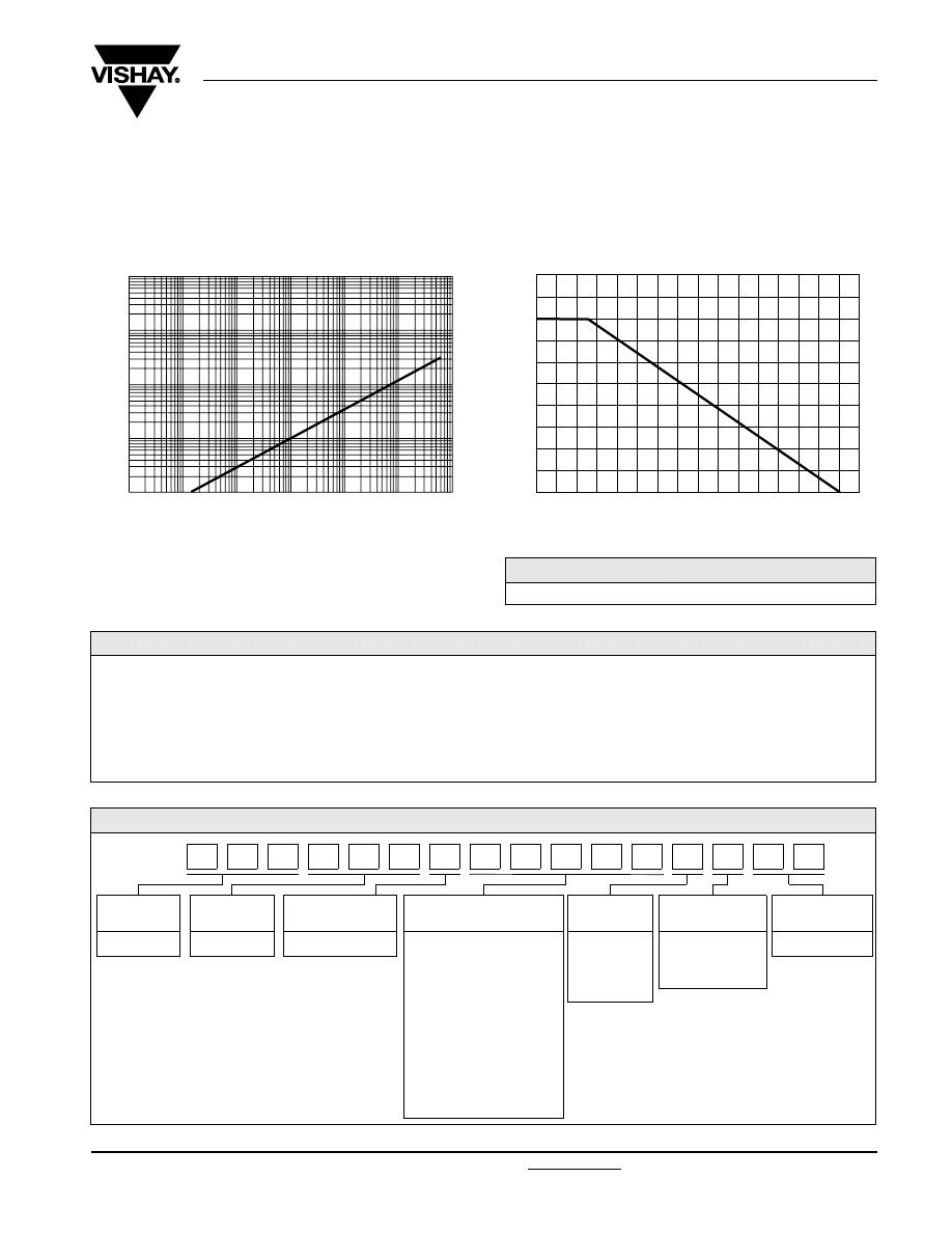
OVERLOADS
In any case the applied voltage must be lower than the
maximum overload voltage of 375 V.
The values indicated on the graph below are applicable to
resistors in air or mounted onto a heatsink.
MARKING
Model, style, resistance value (in
Ω), tolerance (in %),
manufacturing date, VISHAY trademark.
POWER RATING CHART
The temperature of the case should be maintained within the
limits specified.
To improve the thermal conductivity, surfaces in contact
should be coated with a silicone grease and the torque
applied on the screw for tightening should be around 1 Nm.
10
-6
10
-5
10
-4
10
-3
10
-2
S
E
L
U
O
J
N I
Y
G
R
E
N
E
OVERLOAD DURATION IN s
ENER GY CURVE
0.01
0.1
1
10
PACKAGING
Tube of 50 units
0 20 40 60 80 100 120
140 150
100
75
50
25
0
R
%D
E
T
AR
E
W
O
P
CASE TEMPERATURE IN °C
ORDERING INFORMATION
LTO
30
F
2.7 k
Ω
± 1 %
xxx
TU50
e3
MODEL
STYLE CONNECTIONS RESISTANCE VALUE
TOLERANCE
± 1 %
± 2 %
± 5 %
± 10 %
CUSTOM DESIGN
Optional
on request:
Special TCR,
shape etc.
PACKAGING
LEAD (Pb)-FREE
GLOBAL PART NUMBER INFORMATION
GLOBAL
MODEL
SIZE
LEADS
OHMIC VALUE
TOLERANCE
PACKAGING
LEAD (Pb)-FREE
LTO
030
F = Radial leads
The firts four digits are
significant figures and the
last digit specifies the
number of zeros to follow.
R designates decimal point.
48R70 = 48.7
Ω
48701 = 48 700
Ω
10002 = 100 000
Ω
R0100 = 0.01
Ω
R4700 = 0.47
Ω
27000 = 2700
Ω = 2K7 Ω
F = 1 %
G = 2 %
J = 5 %
K = 10 %
T = Tube
Tube 50 pieces
E3 = Pure tin
0
3
0
F
2
7
0
0
T
3
T
O
L
0
J
E

Document Number: 91000
www.vishay.com
Revision: 18-Jul-08
1
Disclaimer
Legal Disclaimer Notice
Vishay
All product specifications and data are subject to change without notice.
Vishay Intertechnology, Inc., its affiliates, agents, and employees, and all persons acting on its or their behalf
(collectively, “Vishay”), disclaim any and all liability for any errors, inaccuracies or incompleteness contained herein
or in any other disclosure relating to any product.
Vishay disclaims any and all liability arising out of the use or application of any product described herein or of any
information provided herein to the maximum extent permitted by law. The product specifications do not expand or
otherwise modify Vishay’s terms and conditions of purchase, including but not limited to the warranty expressed
therein, which apply to these products.
No license, express or implied, by estoppel or otherwise, to any intellectual property rights is granted by this
document or by any conduct of Vishay.
The products shown herein are not designed for use in medical, life-saving, or life-sustaining applications unless
otherwise expressly indicated. Customers using or selling Vishay products not expressly indicated for use in such
applications do so entirely at their own risk and agree to fully indemnify Vishay for any damages arising or resulting
from such use or sale. Please contact authorized Vishay personnel to obtain written terms and conditions regarding
products designed for such applications.
Product names and markings noted herein may be trademarks of their respective owners.
Document Outline
Wyszukiwarka
Podobne podstrony:
Vishay LTO 50
30 Struktury zaleznosci miedzy wskaznikami zrow rozw K Chmura
30 Wydatki rodziny
30 Tydzień zwykły, 30 środa
Fizyka 0 wyklad organizacyjny Informatyka Wrzesien 30 2012
geolog ogolna 30
Ustawa z 30 10 2002 r o ubezp społ z tyt wyp przy pracy i chor zawod
30 Obciążenia obiektów budowlanych, mostów drogowych i kolejowych
wyklad 29 i 30 tech bad
wyklad z kardiologii 30 11 2011
i 30 0 Przywodztwo w organizacji
F II wyklad 11 30 04 12
30 Bay of Biscay
4 30
2001 06 30
więcej podobnych podstron