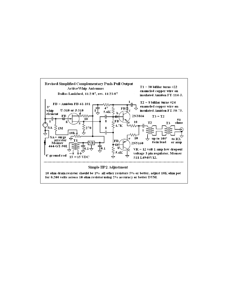
Simplified Complementary Push-Pull Output
Active Whip Antennas
Dallas Lankford, 11/2/07, rev. 12/9/07
High performance active whip antennas often require heat sinks which are not easy to implement, operate off
inconvenient voltages, and use transistors which are virtually impossible to obtain. The high performance active
whip antenna described below is a pleasant exception to all of the complaints above. And IIP2 of my (and other)
previous whips was difficult to adjust because of the special equipment required. In the figure below a simple
IIP2 adjustment is given for a slightly revised simplified complementary push-pull output active whip antenna
which uses a 3 foot whip element.
Recently Horst Maier pointed out to me, based on simulations he had done, that the 2
nd
and 3
rd
order intercepts
of my more complex U-310/2N5109/2N3866/2N5160 active whip antenna were independent of the supply
voltage of the complementary push-pull output part of the circuit down to about 12 volts. That information was
one of the things which motivated me to develop the active whip antenna above. And recently Jon Iza sent me
information about a 1982 East German active whip antenna, the KAA 1000, which included its schematic. The
KAA 1000 used a KP902A MOSFET front end followed immediately by a complementary push-pull output
which also motivated me to develop the active whip antenna above. The transistors used in the KAA 1000 are
believed to be obsolete and mostly unavailable, although one of the KP902A MOSFET's was offered for sale
recently on eBay Germany.
These active whip antennas are simpler than the more complex complementary push-pull output active whip
antennas which were described in a previous article which I have retired. For example, this one does not contain
a 2N5109 source follower between the U-310 FET stage and the 2N3866/2N5160 c-p-p-o stage. And this one
uses a 12 VDC power supply, while the previous more complex active whips used a 24-30 VDC power supply.
The 2N3866/2N5160 c-p-p-o stage of this active whip antenna is operated with 10.3 VDC at the collector of the
1

2N3866. If it is later determined that the c-p-p-o stage should be operated at a higher voltage, then the 47 ohm
collector resistor can be replaced with a small choke. The c-p-p-o stage was operated for many hours at 9 VDC
and no increased non-linearities were observed, so the 10.3 VDC specified here should be satisfactory. With the
47 ohm resistor no heat sinks are needed for the 2N3866 and 2N5160. The U-310 also does not require a heat
sink. Somewhat higher intercepts can be obtained by decreasing the value of the source resistor of the U-310,
but when the source resistor is decreased the U-310 draws more current and so a heat sink for the U-310 would
be desirable or necessary. All parts for this active whip are readily available. For example, you can buy the
2N5160 and 2N3866 on line from
for $9.65 and $2.75 respectively plus
shipping. I believe there is a $39 minimum order. The U-310 is available from many suppliers, including
Mouser. The FB-61-101 ferrite beads and FT-114-J, and FT-50-75 ferrite toroids are also available from many
suppliers. A J-310 may be used instead of a U-310.
Intercepts were measured using a 6 pF coupling capacitor to simulate a 3 foot long whip element (other lengths
may be used within reason). Tones at the input of the 6pF coupling capacitor were +10 dBm (the combiner was
terminated in 50 ohms real at the input of the 6 pF coupling capacitor). This simplified c-p-p-o active whip gain
is about -10 dB in the MW band under these conditions. In some cases a low gain (6 dB) high intercepts post
amplifier might be appropriate. In the MW band IIP2 was +96 dBm (the 10K pot is adjusted for maximum IIP2
in the MW band) and IIP3 was +50 dBm. The tones and intermodulation products for the MW band intercept
measurements were 600 + 700 = 1300 kHz, 2x600 + 700 = 1900 kHz, 1600 – 1100 = 500 kHz, and 2x1100 –
1600 = 600 kHz. As can be seen, MW IIP2 were independent of frequency. This is not the case for other active
whips which I have measured. Some of the SW intercepts were IIP2( 3 + 4 = 7 MHz) = + 81 dBm, IIP3( 3 + 2x4
= 11 MHz) = + 48 dBm, IIP2(4 – 3 = 1 MHz) = +106 dBm, IIP2(9.005 – 6 = 3.005 MHz) = +96 dBm, IIP2(6 +
9 = 15 MHz) = +76 dBm, and IIP3(2x6 + 9 = 21 MHz) = +46 dBm. As can be seen, SW intercepts were not
independent of frequency. This has always been the case for active whips I have measured. Once IIP2 is set for
maximum IIP2 at a particular frequency, such as in the MW band, the pot setting for maximum IIP2 varies little
with respect to frequency. This is not the case for most other active whips I have measured. For the simplified
c-p-p-o active antennas with a 3 foot whip element a simple method of adjusting IIP2 is given in the figure
above below the schematic. It is not known if the simple method of adjusting IIP2 is satisfactory for whip
elements of other lengths.
While the simple method of adjusting IIP2 in the schematic above is not perfect , it does have the advantage of
being simple. A 12 volt voltage regulator is used to establish a constant DC supply voltage because IIP2 of the
active whip is sensitive to changes in its DC supply voltage. A number of FET's were installed one at a time in a
given simplified complementary push-pull output active whip circuit and several parameters for each of the
FET's were measured. No components other than the FET's of the active whip were changed. A 10 ohm 1%
resistor was inserted in series with the FET drain to simplify measuring the total FET current (the voltage drop
across the 10 ohm resistor was measured). The FET current was found to be the most accurate measure of IIP2.
For Vishay/Siliconix U-310's (Mouser 781-U310-E3) maximum IIP2 was with 19.5 mA ± 0.1 mA (0.195 ±
0.001 VDC). For Motorola J-310's maximum IIP2 was with 20.0 mA ± 0.1 mA. For Fairchild J-310's (Mouser
512-J310) maximum IIP2 was with 20.7 ± 0.1 mA. Measurements were made with a Radio Shack DVM having
2% accuracy. The voltage regulator output was measured as 12.04 VDC. The 511-L4940V12 regulator output
is rated as 12.00 ± 0.25 VDC. The 0.200 VDC value was chosen as the adjustment voltage because it is
approximately the mean of the measured voltages. You may use the voltage for the particular FET manufacturer
if you wish. However the sample was not large enough to determine if that is a better strategy.
What do the above numbers mean? For example, is +50 dBm a
sufficiently high IIP3 for an active whip in the MW band, and is +76 dBm
a sufficiently high IIP2 for an active whip in the 19 meter band? Such
questions can be answered by using intercept cascading formulas, which
are given in the figure at right. Usually the units of intercepts are dBm,
but when using the intercept cascading formulas the units of intercepts
2
must be in watts or milliwatts, and gains must be unitless (not in dB). The intercept formulas do not give the
exact result of cascading two devices, but rather the worst case, the case in which the distortion products of the
two devices are in phase and additive. Let's say that an NRD-545 is tuned sufficiently far away from two tones
in the MW band so that its IIP3 is +40 dBm. And let's say that the active whip above, which has +50 dBm MW
band IIP3. Thus the intercepts in watts are 100 and 10 respectively. In the intercept cascading formulas the gain
is the gain of the first device. So we have the intercept IIP3 of the cascade of this active whip followed by the
NRD-545 is given by 1/IIP3 = 1/100 + (1/10)/10, or IIP3 = 50 watts, in which case IIP3 = 10log(50) +30 dBm =
46.9 dBm. So it appears that this c-p-p-o active whip is sufficient for an NRD-545 in this case. Next, let's
consider when the NRD-545 is tuned to the 19 meter band, in which case its IIP2 is approximately +72 dBm for
tones at 6 and 9 MHz. Using the 2
nd
order cascading intercept formula it can be shown that the cascaded
intercept using this c-p-p-o active whip is about 72.2 dBm. So again it appears that this c-p-p-o active whip is
sufficient for an NRD-545. These results suggest that this simplified c-p-p-o active whip antenna is sufficient
for an NRD-545.
This is an excellent active whip antenna. It runs off 12 VDC, requires no heat sinks, uses easy to buy parts, and
has excellent intercepts which are more, and in some cases much more, than adequate for every receiver I am
aware of. What more could one ask for? A miniature version followed by a push-pull Norton feedback
amplifier with virtually the same input intercepts and -5 dB gain... Or no Norton amplifier, -15 dB gain, and
higher intercepts... Take your pick. Unfortunately, the simple method of adjusting IIP2 may not work well for
the Mini Whip variant. A short article describing a correct, but not simple, way to adjust IIP2 is found in
. The traditional, but not entirely accurate, way can also be used.
The neat idea to use a much shorter whip element
than is usually the case, namely 0.1 meter, is due to
Roelof Bakker,
pa0rdt, who introduced the concept
with his Mini-Whip. As a matter of fact, any active
whip can be made into a mini whip merely by using a
much shorter whip element. The advantage of using a
shorter whip element is that lower signal levels are
input to the whip's active circuits which generally
raises the whip's 2
nd
and 3
rd
order intercepts. Most
active whips have higher output signal levels than are
necessary if the receiver with which it is used has
sufficient sensitivity so that overall sensitivity of the
receiving system will not be compromised by a short
whip element. For these tests I used both 4 inch (0.1
meter) and 8 inch (0.2 meter) whip elements mounted
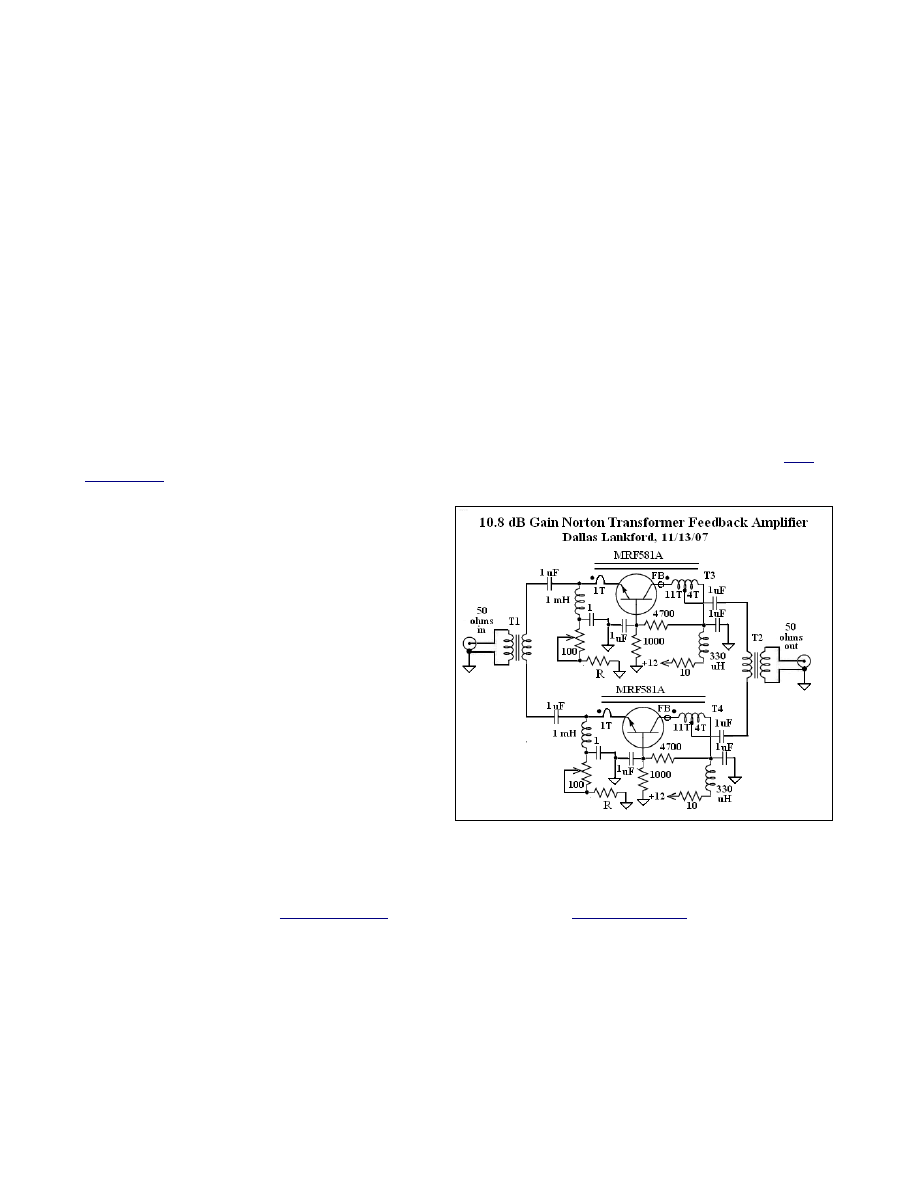
at the top of a 10' PVC pipe. For the 4 inch element,
if your receiver has adequate sensitivity, the push-pull
Norton transformer feedback amplifier at right may
not be needed. If your receiver does not have adequate sensitivity, or if you use a phaser, the amplifier will
probably be needed unless man made noise at your location is high. I found that an 8 inch whip element is
probably a better choice than a 4 inch element. Push-pull transformer feedback Norton amplifiers are described
in detail in several articles in
whip element simulated by a 1.0 pF capacitor, the MW band intercepts were IIP3 = +56 dBm and IIP2 = +106
dBm. Mini whip gain was -15 dB. My p-p Norton transformer feedback amplifier has IIP3 = +35 dBm and IIP2
= +80 dBm or better in the MW band. The intercept cascading formulas gave the worst case intercepts of the
amplified mini whip as IIP3 = +50 dBm and IIP2 = +95 dBm for the MW band. Measurements confirmed these
numbers. Gain of the amplified version was -5 dB.
Yes, the whip element really was 4 inches (0.1 meter). And yes, the mini whip worked very well when mounted
3
at the top of a 10' PVC pipe. I spent most of the morning of 11/12/07 tuning around from 100 kHz to 30 MHz
and comparing the unamplified mini whip to an unamplified relay tuned 15' noise reducing vertical antenna.
The 4 inch whip was mounted on a 10' PVC pole. There was little, if any, difference between the two antennas
with respect to signal levels and signal to noise ratios. However, because the signal output of active whips
(standard or mini) varies with placement, an 8 inch whip element, which had about 10 dB higher output signal
levels than the 4 inch whip element, may be more appropriate, or the 10.8 dB amplifier above can be used. You
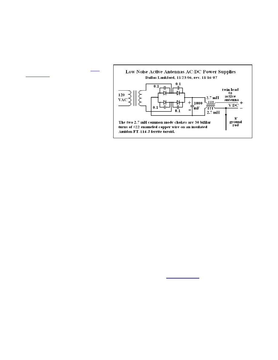
should use a low noise 12 volt power
supply like the one described in
supply may degrade the mini s-c-p-p-o
active whip S/MMN ratio at lower
frequencies, especially in the 120 meter
band, the MW band, and the NDB band,
by as much as 10 dB or more compared
to an amplified 15' noise reducing
vertical. The S/MMN ratio of every
active whip I am familiar with will be
degraded at lower frequencies unless you
use a properly designed and built power
supply and decouple the whip with a
common mode choke. Claims that loop
antennas are wonderful and active whip antennas are terrible continue to appear. But the people making those
claims clearly have not discovered low noise power supplies and common mode chokes. If used with
appropriate low noise power supplies and common mode chokes, active whips that I have tested have no worse
S/MMN ratio than loops (except, perhaps, in a very few isolated cases at the low end of the NDB band and
below), active whips are omnidirectional and don't have to be rotated to see what you are missing, active whips
are easier to phase, especially for broadside nulls, and the active whips of this and some other articles have better
intercepts than any loop you can buy or build. Of course, the best MW and LW antennas are usually passive
noise reducing antennas because they usually have higher intercepts than active antennas, be they whip or loop,
and they usually do not add noise to a receiving system. For example, one of my neighbor's noise sources
appeared last night and wiped out the lower NDB band and below for several hours while I was using the active
whip. Changing to battery power made no difference. However, a 15' amplified noise reducing vertical located
no more than 10' away from the active whip was completely free of the noise. This was very puzzling. At the
time I experienced the noise in the lower NDB and below the active whip was not grounded. When I grounded
the active whip later with a 4' ground rod as shown on the schematic at the beginning of this article the noise
disappeared completely. For a short period of time I could make the noise come and go by disconnecting and
connecting the 4' ground rod. But later the noise had disappeared with or without the 4' ground rod connected.
Because of the intermittent nature of the noise (it has not reappeared for several days while I have been
listening), I am not really certain if the 4' ground rod eliminated the noise, of if its intermittent nature eliminated
the noise naturally. What I need is a remote (relay operated) switch at the ground rod so that I can connect and
disconnect it instantaneously while listening. However, the 4' ground rod does eliminate a low level noise
source which slightly degrades sensitivity in the lower NDB band and below. Also, when using an AC-DC
power supply for the active whip a separate 8' ground rod sometimes eliminates noise coupled by the power
supply; see the schematic above, and additional details in an article in
Sensitivity of the mini whip was significantly affected by the height of its element. At ground level, sensitivity
was unacceptable; at 5' height sensitivity was kinda OK; at 10' sensitivity was fine; at 20 feet there seemed to be
a slight improvement in signal to noise ratio below the bottom end of the NDB band (the low level noise source
was eliminated). On the other hand, with a 3' whip element sensitivity at 5' height was fine. For me a 3' whip
element is more appropriate because I will use two of them as a phased array, and all phasers inherently have
some loss.
4
Wyszukiwarka
Podobne podstrony:
Complementary Push Pull Amplifiers A Critical Review
Simplified Complementary P P Output Active Whip
PUSH I PULL, Logistyka, transport
HST PUSH & PULL czyli jak podrasować HST
(Ebook Audio Acoustics HiFi DIY)Push Pull Electrostatic Speaker Model Theory[de Vissere]{by shack
(push pull)pdb183 gtr
29. Strategia pull i push, Materiały PSW Biała Podlaska, ZiPM- ćwiczenia
The Complex Simplicity of Meta States
JE Marrying Push and Pull Strategies SC DIGEST
lecture3 complexity introduction
L 3 Complex functions and Polynomials
Popular Mechanics Repairing Power Antennas
Complexes
LES PRONOMS COMPLEMENT
Complete Timeline of Darkest Powers Stories 2011 04 13
Free Energy & Technological Survival Homemade Wireless Antenna
501 Sentence Completion Questions
Alemão urgente! Para brasileiros 15 Complementação
Complete Circuit diagram and plans
więcej podobnych podstron