Smiley’s Workshop 12: ALP Projects
Smiley’s Workshop 12: ALP Projects
Joe Pardue May 18, 2009
Figure 1: Layout for Cylon Optometry
In this and the next few Workshops, we will continue with the ALP (AVR Learning
Platform). We will take a look at some things that will get us quickly using more of the
components from the Smiley Micros Arduino Projects kit (available from Nuts&Volts
and Smiley Micros).
Recap:

Smiley’s Workshop 12: ALP Projects
In Workshop 9 we began using a new development board, the Arduino Duemilanove
recognizing that The Arduino Way (TAW) is a very simple and easy way to begin using
microcontrollers. We learned, that while TAW uses a C-like language and has an easy to
use IDE, it does not IMHO (In My Humble Opinion) provide a clear path to learning the
C programming language or the details of the AVR architecture -- both of which are our
long-term goals for this Workshop series. To help overcome this, we learned how to
convert TAW code to work with the more standard IMHO Atmel AVR tools:
AVRStudio, WinAVR, and AVRDude using A C Way (ACW). And we put together the
AVR Learning Platform (ALP) that uses the Smiley Micros Arduino Projects Kit
(available from Nuts&Volts and Smiley Micros). This will provide our hardware
development system for many Workshops to come.
This month we will do another communications project, learn to read the voltage across a
potentiometer and then redo for the ALP the Cylon Optometry code that we first did for
the Butterfly back in Workshop 5.
The ASCIITable Example in TAW and ACW
You can find the TAW version of the ASCIITable example in the Arduino IDE under the
menu File\Sketchbook\Examples\Communication\ASCIITable. In the ACW version we
show TAW code commented out (marked with // to hide it from the compiler) to make it
easier to compare the TAW and ACW versions. We will exercise the printf() function,
and learn that it doesn’t have a binary formatter so we do without that for now.
Be sure and review Workshop 9 and 10 on converting code from TAW to ACW. From
those discussions, you should be able get AVRStudio to find libACW001 and compile
the following code:
// ASCII Table - ACW
// Joe Pardue April 10, 2009
// This program outputs an ASCII Table to
// a PC Terminal.
#include "libACW001.h"
int main(void)
{
init(); // Initialize private stuff
setup(); // Setup the public stuff
for (;;) loop(); // Call loop() forever;
return 0; // You never get here.
}

Smiley’s Workshop 12: ALP Projects
void setup()
{
//Serial.begin(9600); //TAW
serialBegin(9600);
// prints title with ending line break
// Serial.println("ASCII Table ~ Character Map"); //TAW
printf("ASCII Table ~ Character Map\n");
// wait for the long string to be sent
delay(100);
}
void loop()
{
// prints value unaltered, first will be '!'
//Serial.print(number, BYTE);
printf("%c", number);
// prints value as string in decimal (base 10)
//Serial.print(", dec: ");
//Serial.print(number);
printf(", dec: %u",number);
// prints value as string in hexadecimal (base 16
//Serial.print(", hex: ");
//Serial.print(number, HEX); )
printf(", hex: 0x%x",number);
// prints value as string in octal (base 8)
//Serial.print(", oct: ");
//Serial.print(number, OCT);
printf(", oct: %o",number);
// also prints ending line break
printf("\n");
// if printed last visible character '~' #126 ...
if(number == 126) {
// loop forever
while(1){//true) {
continue;
}
}
// to the next character
number++;
// allow some time for the Serial data to be sent
Smiley’s Workshop 12: ALP Projects
delay(100);
}
As discussed in earlier Workshops, compile this and upload it using the following two
lines in the cmd window to move to the correct directory and run AVRDude:
Change directories with:
cd \ArduinoToAVRStudio-ASCII Table\default
Upload the code with:
avrdude -p m328p -c avrisp -P com6 -b 57600 -F -U flash:w:ASCIITable.hex
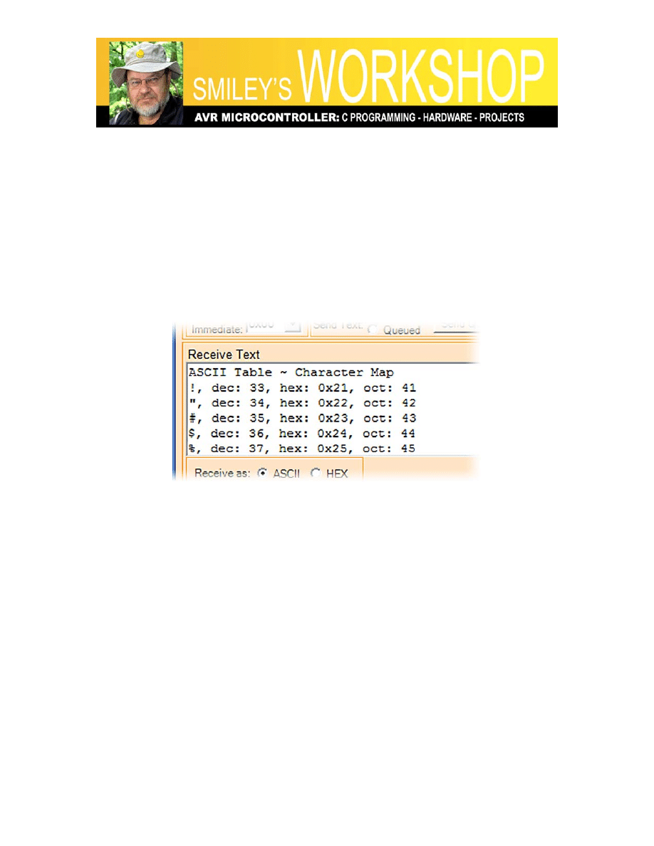
Figure 2: ASCII Table in Developer’s Terminal
In the Developer’s Terminal, I set the Receive Text window to the font Courier New 10-
point so that the characters would align. You may also see that the terminal occasionally
adds an extra blank line – a bug in the terminal I’ll get to one of these days. Developer’s
Terminal was discussed in Smiley’s Workshop4: Teaching the Butterfly to Talk. You can
download both the Developer’s Terminal and that Workshop from
www.smileymicros.com
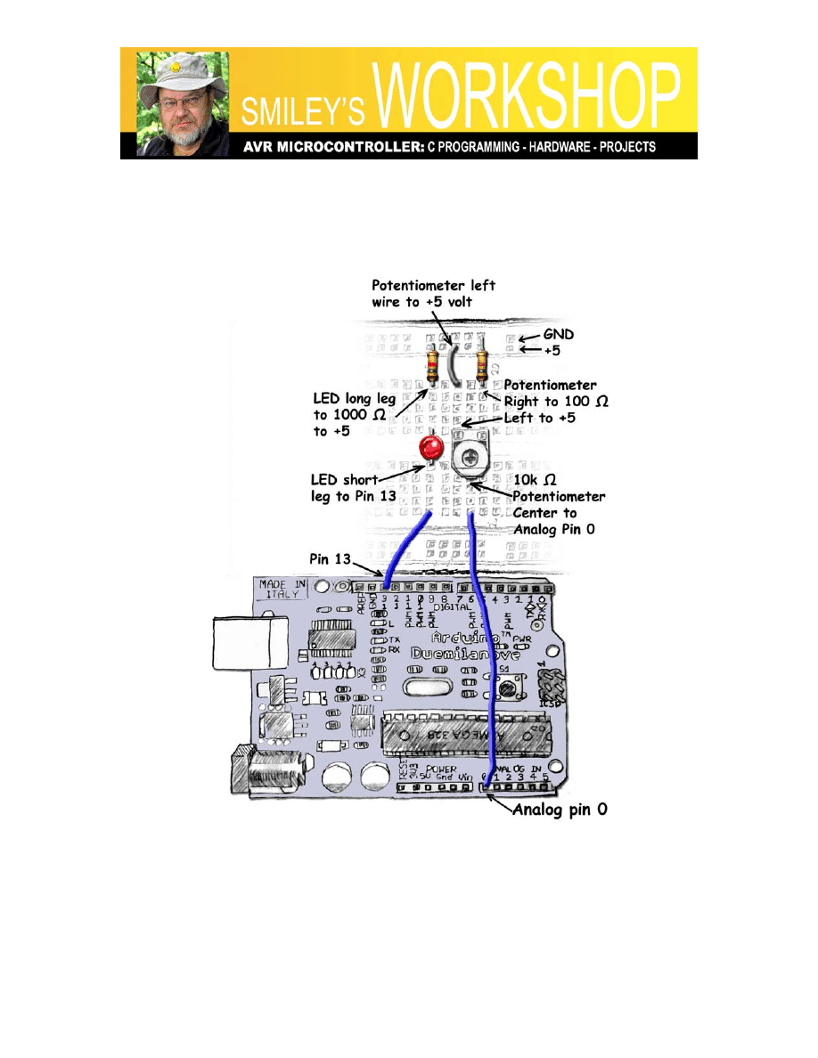
Analog Input: Reading a Potentiometer.
Let’s do a couple of projects with the Arduino Projects Kit potentiometer shown in
Figure 3: Potentiometer schematic. The schematic for this project is shown in Figure 4:
Schematic for potentiometer with LED. The layout using the breadboard on the ALP is
shown as a drawing in Figure 5: ALPs AnalogInput layout
Note that in addition to the potentiometer we have a 100 Ω resistor in this circuit that
prevents us from shorting the power to ground if we set the potentiometer to zero Ω. The
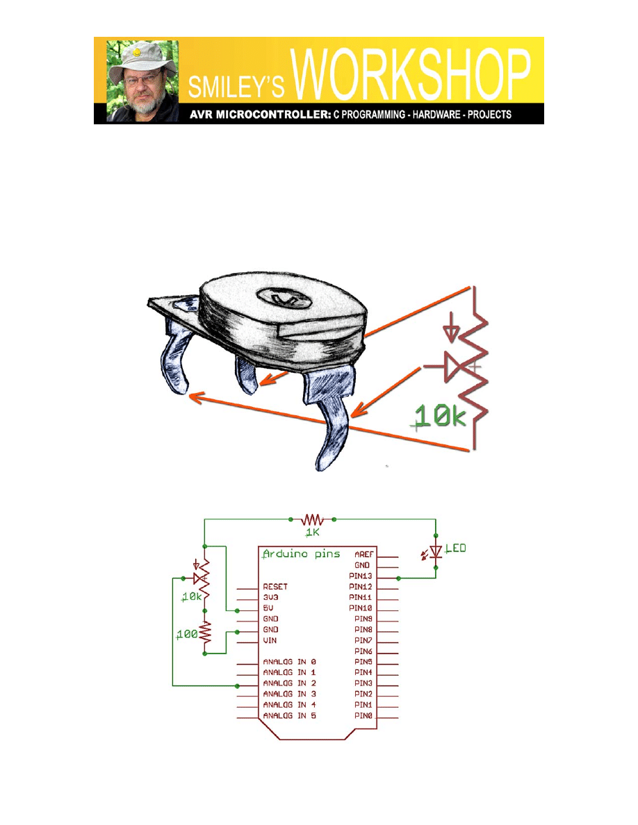
Smiley’s Workshop 12: ALP Projects
analog reading will be for 5 volts across a resistance for the potentiometer + the resistor:
from a maximum of 10100 Ω down to a minimum of 100 Ω. The AVR ADC will
measure in 1024 steps, with the 1023 value for the full 5 volts, but since we have the 100
Ω resistor, our lowest ADC value should be about 1% of the full 1024 range or roughly
10. In my actual test, the low value was 7, but remember that both the pot and the resistor
values have associated errors, so without some sort of external calibration, we will may
be off a bit.
Figure 3: Potentiometer schematic symbol
Smiley’s Workshop 12: ALP Projects
Figure 4: Schematic for potentiometer with LED
Figure 5: ALPs AnalogInput layout
I recommend that first you test the hardware using the original AnalogInput from the
Arduino IDE example code - the TAW version. BUT change the Analog pin from 2 to 0
in the TAW code to match the hardware shown. It doesn’t matter which Analog pin you
use as long as your code matches the hardware. Once you see that the hardware works -
the LED
blink rate varies as you turn the potentiometer to the left and right - you can

Smiley’s Workshop 12: ALP Projects
move on to the slightly harder ACW source code version with reasonable confidence that
the hardware is correct.
AnalogInput Example Ported from TAW to ACW
// AnalogInput
// mostly 'borrowed' from the Arduino example
#include "libACW001.h"
// select the input pin for the potentiometer
int potPin = 0;
// select the pin for the LED
int ledPin = 13;
// variable to store the value from the sensor
int val = 0;
int main(void)
{
init(); // Initialize private stuff
setup(); // Setup the public stuff
for (;;) loop(); // Call loop() forever;
return 0; // You never get here.
}
void setup()
{
// declare the ledPin as an OUTPUT
pinMode(ledPin, OUTPUT);
}
void loop()
{
// read the value from the sensor
val = analogRead(potPin);
// turn the ledPin on
digitalWrite(ledPin, HIGH);
// stop the program for some time
delay(val);
// turn the ledPin off
digitalWrite(ledPin, LOW);
// stop the program for some time
delay(val);
}
Change directories with:
cd \ArduinoToAVRStudio-AnalogInput\default
Upload the code with
:
avrdude -p m328p -c avrisp -P com6 -b 57600 -F -U flash:w:AnalogInput.hex

Smiley’s Workshop 12: ALP Projects
Just as an aside, this was the first time I was actually able to copy code from TAW,
change it to ACW, and have it compile, and upload with no errors. All the prior examples
took some debugging. I tell you this so that you know that getting all this right isn’t easy,
even for the guy who is trying to teach it. Chant: ‘Patience Persistence Payoff’.
The Dimmer Example in TAW and ACW
In Workshop 11 we saw how to send out serial data from the AVR to a terminal on the
PC, but what about the other direction? In old-fashioned C you’d use some version of the
scanf() function to match the printf(), but we aren’t going to do that. We will use some
functions in libACW001.a that replace the TAW serial functions, as discussed in the last
Workshop.
Again, I suggest that before you do this ACW, that you do it TAW with the Dimmer
example from: File/Sketchbook/Examples/Communication/Dimmer. The following is the
ACW version with the original TAW functions commented out:
#include "libACW001.h"
// Use a pin with PWM
int ledPin = 9;
int main(void)
{
init(); // Initialize private stuff
setup(); // Setup the public stuff
for (;;) loop(); // Call loop() forever;
return 0; // You never get here.
}
void setup()
{
// begin the serial communication
//Serial.begin(9600);
serialBegin(9600);
pinMode(ledPin, OUTPUT);
}
void loop()
{
byte val;
// check if data has been sent from the computer
//if (Serial.available()) {
if (serialAvailable()) {
Smiley’s Workshop 12: ALP Projects
// read the most recent byte (which will be from 0 to 255)
//val = Serial.read();
val = serialRead();
// set the brightness of the LED
analogWrite(ledPin, val);
}
}
Change directories with:
cd \ArduinoToAVRStudio-Dimmer\default
Upload code with:
avrdude -p m328p -c avrisp -P com6 -b 57600 -F -U flash:w:Dimmer.hex
This program continuously checks to see if there is a byte of data available on the serial
port and if so uses that data to set the LED brightness. You can test it with Developer’s
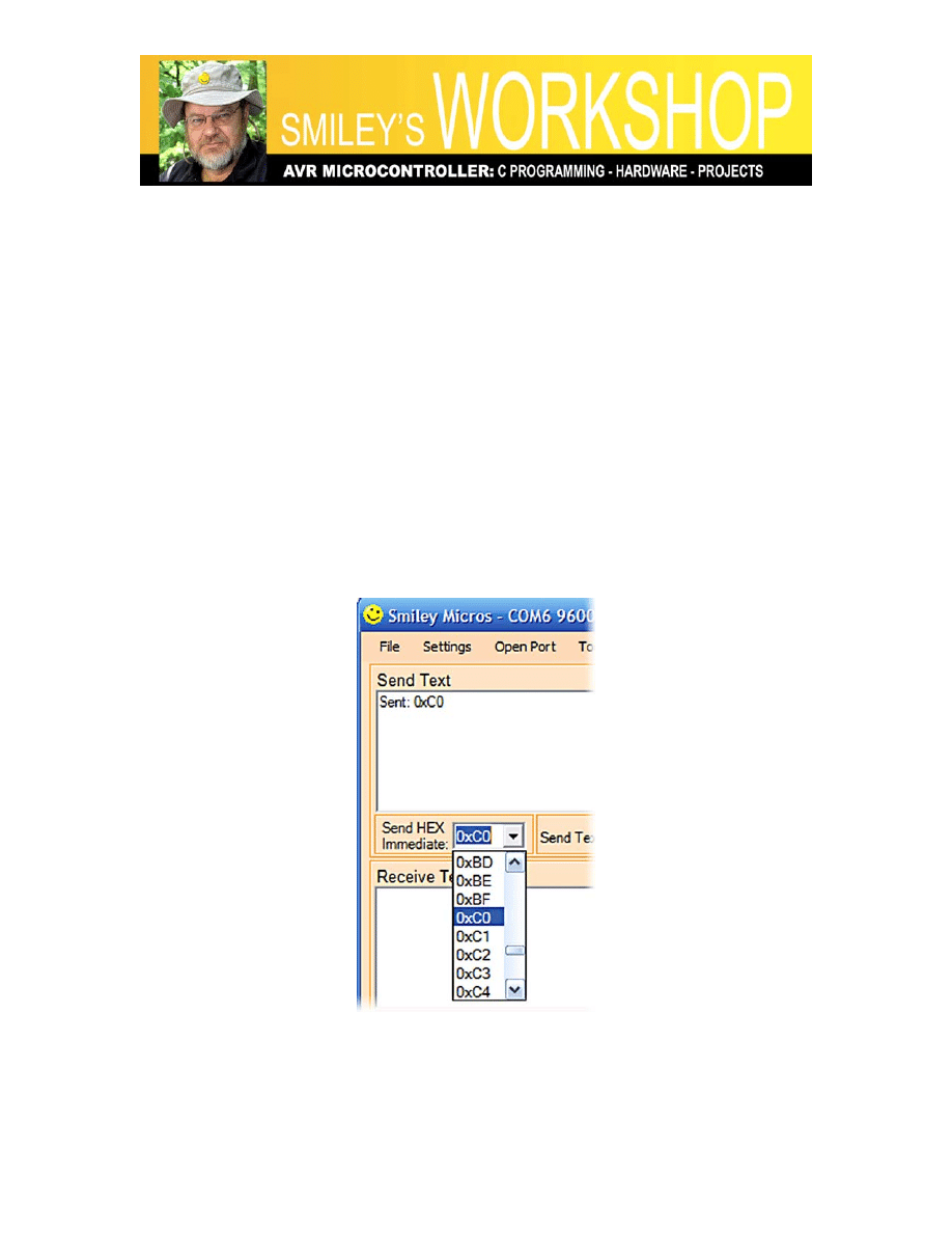
Terminal (we saw how to use it in earlier Workshops). You can use the ‘Send HEX
Immediate:’ as shown in Figure 6: Send HEX Immediate to play with dimming the LED.
Figure 6: Send HEX Immediate

Smiley’s Workshop 12: ALP Projects
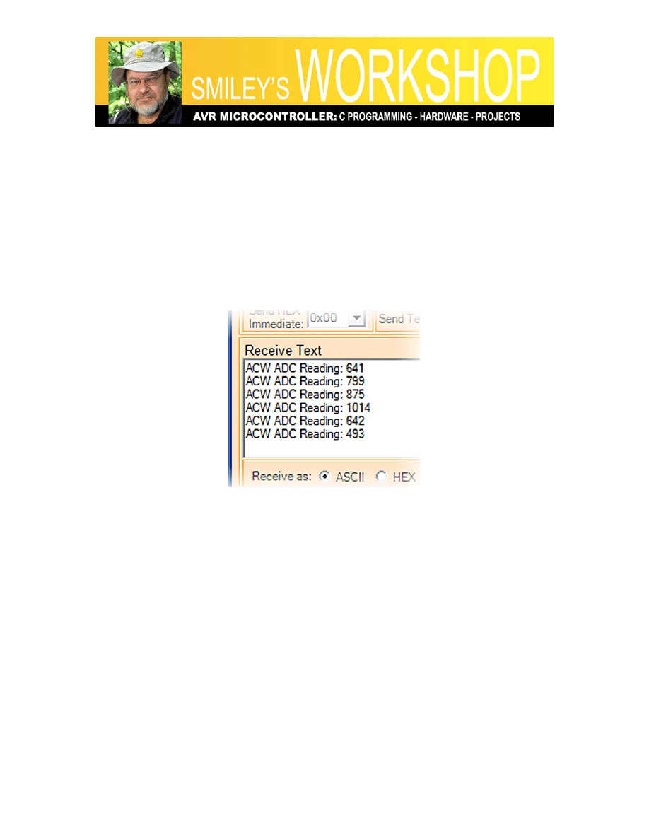
Read a Potentiometer with a Terminal
This project, ReadPot, isn’t taken from an Arduino IDE example, but it is based on Tom
Igoe’s example shown in the Arduino Serial.print(data) web page. As usual, I leave in the
TAW code commented out to show the TAW versus ACW differences. The output read
by Developer’s Terminal should look something like that shown in Figure 7: ACW
ReadPot Output.
ReadPot in ACW
// ReadPot ACW
// Joe Pardue March 24, 2009
// based on Tom Igoe's example in the
// Arduino Serial.print(data) documentation
#include "libACW001.h"
// variable to hold the analog input value
int analogValue = 0;
int main(void)
{
init(); // Initialize private stuff
setup(); // Setup the public stuff
for (;;) loop(); // Call loop() forever;
return 0; // You never get here.
}
void setup()
{
// begin the serial communication
//Serial.begin(9600);
serialBegin(9600);
}
void loop()
{
// read the analog input on pin 0
analogValue = analogRead(0);
// print prolog to value
//Serial.print("ADC Reading: ");
printf("ACW ADC Reading: ");
// print as an ASCII-encoded decimal
//Serial.print(analogValue, DEC);
//Serial.println(); // print a newline
Smiley’s Workshop 12: ALP Projects
printf("%d\n", analogValue);
// delay 1 second before the next reading:
delay(1000);
}
Change directories with:
cd \ALP ReadPot\default
Upload code with:
avrdude -p m328p -c avrisp -P com6 -b 57600 -F -U flash:w:ReadPot.hex
Figure 7: ACW ReadPot Output
Smiley’s Workshop 12: ALP Projects
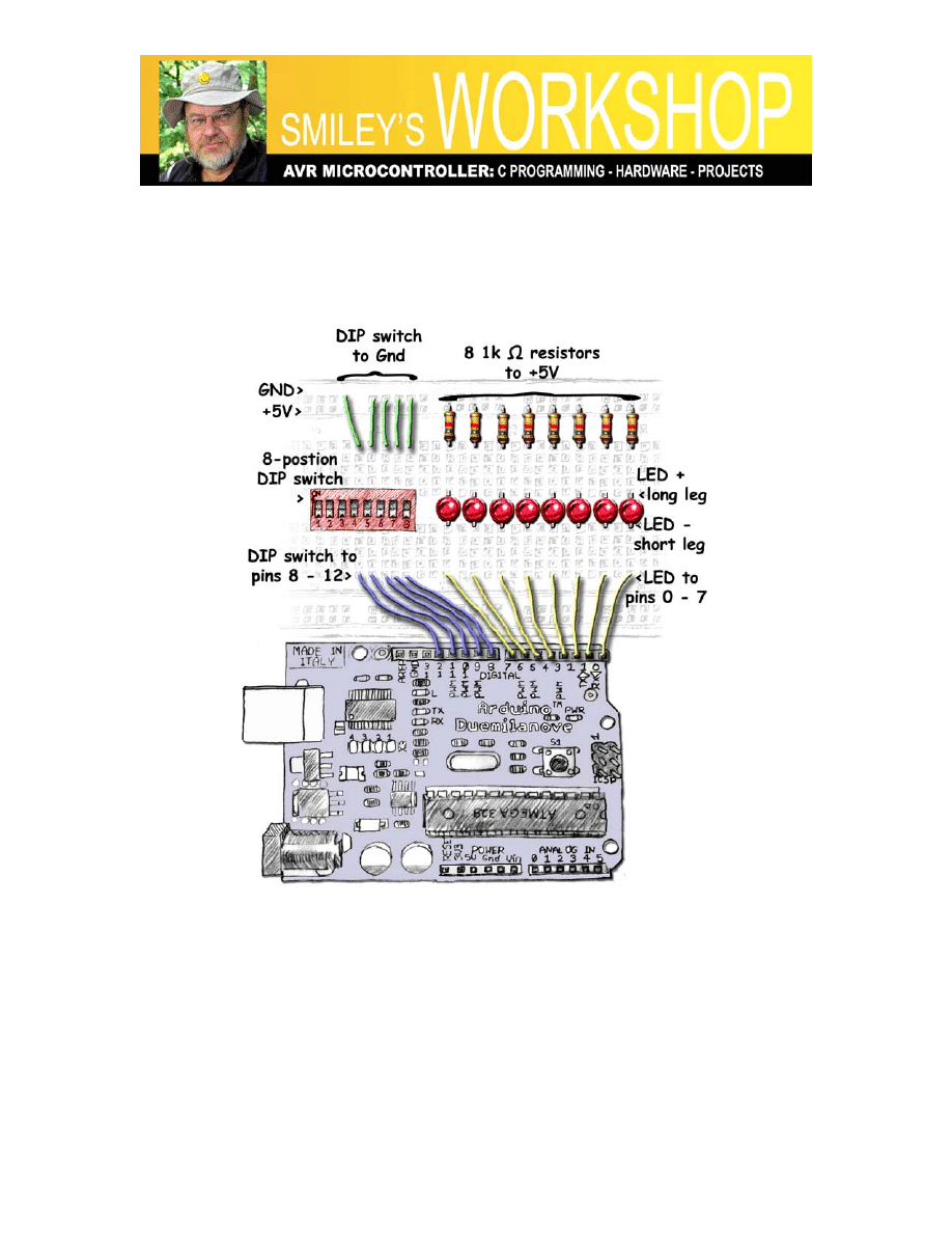
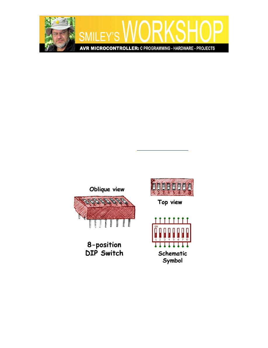
Cylon Optometry Redux
In Workshop 5 we used an 8-position DIP switch and 8-LEDs to demonstrate some
principles for using binary numbers in C with the Butterfly. We will do a subset of that
project for the ALP. We are forced to use a subset since we can only read 5 DIP switches
if we want to also use the 8 LEDs with the Arduino board. We will sacrifice speed
control from the original project that used 4 switches to encode 16 speeds; we will only
use 1 switch for 2 speeds.
If this statement doesn’t make sense to you: “There are exactly 10 types of people in the
world. Those who understand binary and those who don’t” then please read Smiley’s
Workshop 5. AND you might also find useful: Smiley’s Workshop 5 Supplement 1- Cylon
Optometry.pdf. Both of these can be found on
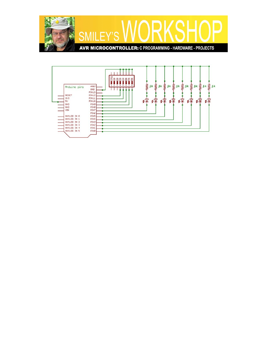
drawing for this project was shown at the beginning of the Workshop in Figure 1: Layout
for Cylon Optometry, the schematic follows in Figure 9: Schematic for Cylon Optometry.
The Hardware
Figure 8: DIP Switch Drawing and Schematic
Smiley’s Workshop 12: ALP Projects
Figure 9: Schematic for Cylon Optometry
Scroll Cylon Eyes
This time we will show the code in both TAW and ACW since there is no example in the
Arduino IDE or on it’s website.
Cylon Eyes TAW:
// CylonEyes TAW
// Joe Pardue April 11, 2009
void setup()
{
// Init port pins
DDRB = 0x00; // set port B for input
DDRD = 0xFF; // set port D for output
}
void loop()
{
for(int i = 1; i <= 128; i = i*2)
{
PORTD = ~i;
delay(128);
}
for(int i = 128; i > 1; i -= i/2)
{
PORTD = ~i;
delay(128);

Smiley’s Workshop 12: ALP Projects
}
}
Cylon Eyes ACW:
For the ACW version we drop the ‘~” thus changing the polarity of the LED scroll so that
we can make sure we tell the TAW and ACW versions apart.
// CylonEyes ACW
// Joe Pardue April 11, 2009
#include "libACW001.h"
int main(void)
{
init(); // Initialize private stuff
setup(); // Setup the public stuff
for (;;) loop(); // Call loop() forever;
return 0; // You never get here.
}
void setup()
{
// Init port pins
DDRB = 0x00; // set port B for input
DDRD = 0xFF; // set port D for output
}
void loop()
{
for(int i = 1; i <= 128; i = i*2)
{
PORTD = i;
delay(128);
}
for(int i = 128; i > 1; i -= i/2)
{
PORTD = i;
delay(128);
}
}
Change directories with:
cd \ALP CylonEyes\default
Upload code with:
avrdude -p m328p -c avrisp -P com6 -b 57600 -F -U flash:w:CylonEyes.hex

Smiley’s Workshop 12: ALP Projects
Show DIP input on LED output
Before we use the DIP switch to control our Cylon Eyes, let’s make sure we can read its
state and show that state on the LEDs.
DIPLEDTAW
// DIPLEDTAW
// Joe Pardue April 11, 2009
void setup()
{
// Init port pins
DDRB = 0x00; // set port B for input
PORTB = 0xFF; // set port B pullups
DDRD = 0xFF; // set port D for output
}
void loop()
{
PORTD = PINB;
}
DIPLEDACW
// DIPLEDTAW
// Joe Pardue April 11, 2009
#include "libACW001.h"
int main(void)
{
init(); // Initialize private stuff
setup(); // Setup the public stuff
for (;;) loop(); // Call loop() forever;
return 0; // You never get here.
}
void setup()
{
// Init port pins
DDRB = 0x00; // set port B for input
PORTB = 0xFF; // set port B pullups
DDRD = 0xFF; // set port D for output

Smiley’s Workshop 12: ALP Projects
}
void loop()
{
PORTD = PINB;
}
Change directories with:
cd \ALP DIPLED\default
Upload code with:
avrdude -p m328p -c avrisp -P com6 -b 57600 -F -U flash:w:DIPLED.hex
Read DIP switch positions on Terminal
Now we have a little problem if we want to read the DIP input, show it on the LEDs, and
send it out the serial port. The problem is that the lowest 2 PORTD pins that drive the
rightmost 2 LEDs are also used to show traffic on the serial port. So we use the shift
operator (see Workshop 5) to move the five lower bits on the DIP switch left three
positions so that they will be shown on the leftmost 5 LEDs.
DIPLEDSerialTAW
// DIPLEDSerialTAW
// Joe Pardue April 11, 2009
int value = 0;
void setup()
{
// Init port pins
DDRB = 0x00; // set port B for input
PORTB = 0xFF; // set port B pullups
DDRD = 0xFF; // set port D for output
Serial.begin(9600);
}
void loop()
{
// load PORTB pins into value
value = PINB;
// shift value left 3 positions
PORTD = (value << 3);
Serial.print("value = ");

Smiley’s Workshop 12: ALP Projects
Serial.println(value);
delay(1000);
}
DIPLEDSerialACW
// DIPLEDSerialACW
// Joe Pardue April 11, 2009
#include "libACW001.h"
int value = 0;
int main(void)
{
init(); // Initialize private stuff
setup(); // Setup the public stuff
for (;;) loop(); // Call loop() forever;
return 0; // You never get here.
}
void setup()
{
// Init port pins
DDRB = 0x00; // set port B for input
PORTB = 0xFF; // set port B pullups
DDRD = 0xFF; // set port D for output
//Serial.begin(9600);
serialBegin(9600);
}
void loop()
{
// load PORTB pins into value
value = PINB;
// shift the value left 3 positions
PORTD = (value << 3);
//Serial.print("value = ");
//Serial.println(value);
printf("value = %d\n",value);
delay(1000);
}
Change directories with:
cd \ALP DIPLEDSerial\default
Upload code with:
avrdude -p m328p -c avrisp -P com6 -b 57600 -F -U flash:w:DIPLEDSerial.hex

Smiley’s Workshop 12: ALP Projects
We have now shown all the components for the Cylon Optometry, but we’ve run out off
space, so the final source code that provides the blink patterns is in the Workshop12
Sourcecode.zip file under /ACW/Cylon Optometry ACW/ and /TAW/Cylon Optometery
TAW/. Remember that this is a repeat of some concepts from Workshop 5, so you may
want to refer back to that if all this seems a bit rushed.
The Arduino Projects Kit:
Smiley Micros and Nuts&Volts are selling a special kit: The Arduino Projects Kit.
Beginning with Workshops 9 we started learning simple ways to use these components,
and in later Workshops we will use them to drill down into the deeper concepts of C
programming, AVR microcontroller architecture, and embedded systems principles.
With the components in this kit you can:
• Blink 8 LEDs (Cylon Eyes)
• Read a pushbutton and 8-bit DIP switch
• Sense Voltage, Light, and Temperature
• Make Music on a piezo element
• Sense edges and gray levels
• Optically isolate voltages
• Fade LED with PWM
• Control Motor Speed
• And more…
And a final note: the USB serial port on the Arduino uses the FTDI FT232R chip was
discussed in detail in the article “The Serial Port is Dead, Long Live the Serial Port’ by
yours truly in the June 2008 issue of Nuts&Volts.
You can also get the book “Virtual
Serial Programming Cookbook” (also by yours truly) and associated projects kit from
either Nuts&Volts or Smiley Micros.
LINKS: You can find the source code for this article in Workshop12.zip on the
Nuts&Volts and Smiley Micros websites.
Document Outline
- Smiley’s Workshop 12: ALP Projects
Wyszukiwarka
Podobne podstrony:
lp a Worksheet 12
eim4 12 worksheet
eim2 12 worksheet
eim3 12 worksheet
eim4 12 worksheet
12 Workshop AutoHifi in strich 8
CE Elementary module 12 web worksheet
islcollective worksheets beginner prea1 elementary a1 elementary school writing verb to be 12 oct 20
islcollective worksheets beginner prea1 elementary a1 elementary school reading spelling writing pre
wykład 12 pamięć
Figures for chapter 12
Mechanika techniczna(12)
Socjologia wyklad 12 Organizacja i zarzadzanie
CALC1 L 11 12 Differenial Equations
zaaw wyk ad5a 11 12
budzet ue 11 12
więcej podobnych podstron