
PROJECTS
MICROCONTROLLERS
48
elektor - 3/2009
Another Brisk Day Today!
Temperature measurement
with the ATM18 and a 1-wire bus
Wolfgang Rudolph, Burkhard Kainka and Udo Jürß (Germany)
We all know what ‘cold’ means, but cold is not a physical quantity. If we define it as the absence of
heat, we’re heading in the right direction in terms of physics. Like darkness, cold is not ‘real’, but in
subjective human terms we can certainly talk about cold, dark nights. A more objective approach is to
measure the temperature, which is what we have in mind this time with our ATM18 system.
Where does the concept of temperature
come from? The path from the subjec-
tive sense of temperature to an objec-
tive, measurable physical quantity was
not easy. The vibration of atoms and
molecules, which becomes stronger as
the temperature increases, exceeded
our mental grasp for a long time.
However, around 1700 (the exact
date is not known) Isaac Newton
had already discovered the princi-
ple of heat. He devised a temperature
scale with its zero point at the tem-
perature of freezing water. One degree
on the Newton scale corresponds to
3.03 degrees Celsius. Other tempera-
ture scales followed quickly, all with
different sizes of degrees. The Rømer
scale (1 Rø = 1.9 C) was defined in
1701, followed by the Fahrenheit scale
(1 F = 0.56 C) in 1714 and the Réau-
mur scale in 1730 (1 Re = 1.25 C). The
Celsius scale was defined in 1742, and
the Kelvin scale, in 1848. The degree
spacing of the Kelvin scale is the same
as that of the Celsius scale.
The various temperature scales differ
not only in the size of their degrees, but
also in their reference points. The Fahr-
enheit scale, which still predominates
in the USA, is especially strange: the
zero point (0 F = –18.3 C) is defined
by a mixture of ice, water and sea
salt, while the body temperature of a
healthy person (35.6 °C) serves as the
upper reference point. To make things
even more complicated, there are only
96 graduations between the two refer-
ence points instead of 100. This means
that a person with a body temperature
of 100 F has a slight fever (37.8 C).
When the metric system of units (the
SI system, which stands for Système
International d’Unités) was intro-
duced in 1960, it included only one
unit for temperature – the Kelvin – with
degrees Celsius as a derived unit. The
degrees of both scales are the same,
but the zero point of the Kelvin scale
is absolute zero, which corresponds to
–273.15 C. Naturally, this means that
0 C = 273.15 K. This interesting topic
is discussed in great detail in a very
informative article at [1].
Only quantities that can be measured
can be put to use for other purposes.
In the old days, when we (as elec-
tronics enthusisasts or professionals)
wanted to know how warm or cold it
was, we had a relatively limited selec-
tion of inexpensive temperature sen-
sors to choose from. The most com-
monly used sensors were thermistors,
which are resistors whose resistance
depends on their temperature – but not
linearly. You could connect a milliam-
père meter in series with a thermistor
and read the temperature from a home-
made scale. For any further processing,
the non-linear characteristic had to be
linearised. Instead of making complex
calculations, people often used tables
of resistance versus temperature for
this purpose. It was sometimes neces-
sary to generate your own table.
However, those days are long gone.
Today sensors with integrated signal
conditioning, which output the meas-
ured temperature in digital form and
do not require any additional circuitry,
are available at low prices. The sen-
sors used in the project described in
this article even draw their operating
power from the data line, which means
they can be used with what is called a
‘one-wire network’.
The one-wire hoax
The one-wire technology was devel-
oped by Dallas Semiconductor, which
now belongs to Maxim. This network
technology uses a twisted-pair ‘bus’
for all of its communication. Here ‘one
wire’ is clever marketing ploy that is
only true if you don’t count the ground
wire. Naturally, the bus needs a ground
line as well as a data line in order to
work properly. What makes this tech-
nology attractive is that you can con-
nect many devices in parallel to this
two-wire bus.
The data line must be pulled to +5 V
by a pull-up resistor. This represents
the ‘high’ level. To write a logic 1, the
bus is pulled to the Low level (ground)
for less than 15 µs. To transmit a logic
zero, the bus is also pulled Low, but in
49
3/2009 - elektor
Another Brisk Day Today!
this case for at least 60 µs. To initiate a
communication session, the bus mas-
ter (in our case the ATmega) performs
a bus reset by pulling the bus Low
for longer than 480 µs. It then waits
for responses from the slave devices,
in our case the temperature sensors,
which issue an extended Low pulse.
If the master wants to communicate
with a particular slave, it sends the
address of the slave device and initi-
ates a handshake. After the slave has
responded, the master sends com-
mands (which may be device-specific)
and waits for responses. Every compo-
nent with a 1-wire port has a unique
64-bit serial number. These numbers
are assigned to the components when
they are manufactured, and they can-
not be changed.
There are various types of sensors on
the market. We chose the DS1820 and
its successor, the DS18S20, which is
functionally equivalent and pin-com-
patible with the DS1820 and also has
the type designation ‘DS1820’ printed
on the package. The specifications of
this device are listed in Table 1, and
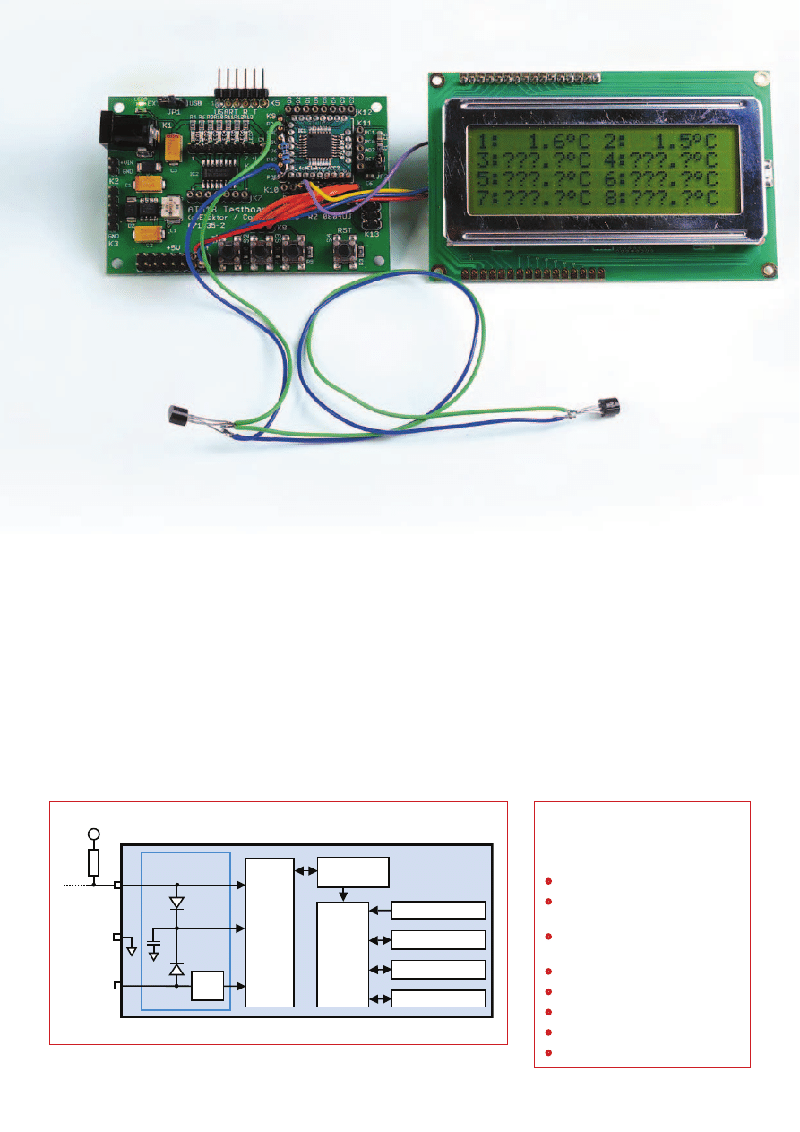
its block diagram is shown in Figure 1.
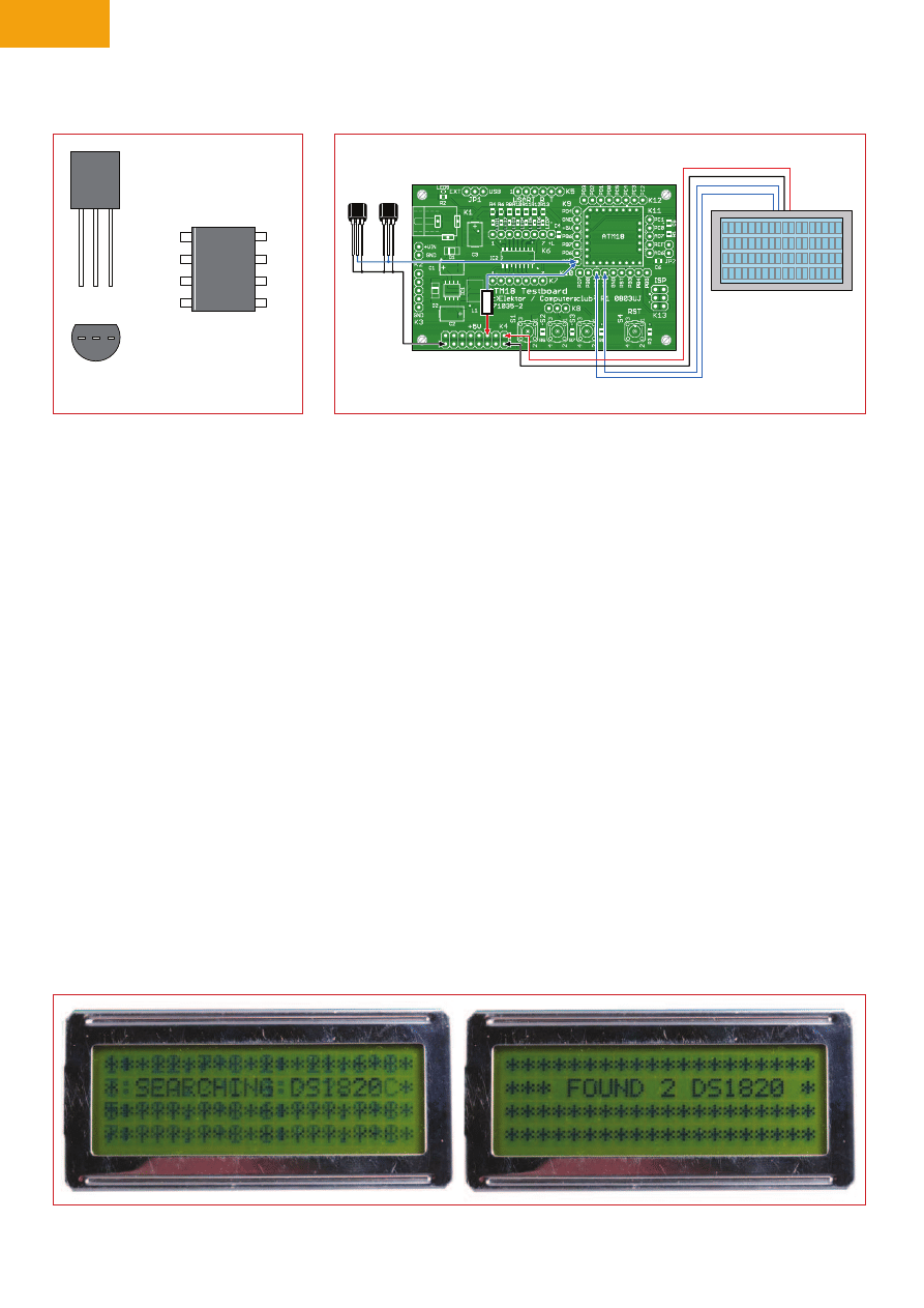
The pin assignments of the two pack-
age options are shown in Figure 2.
The maximum achievable bus length
depends on the value of the pull-up
resistor connected between the data
line (DQ) and the positive supply volt-
age V
CC
(+5 V). Based on practical
experience, up to 80 m (250 ft) can be
regarded as reliable. Longer values
are possible, but external noise on the
bus increases with the length of the
network. The maximum cable length
can be increased by connecting a sec-
ond pull-up resistor (with a value in
the range of 1.5 to 10 k ) between
the data line and V
CC,
but this slightly
degrades the measurement accuracy
due to increased internal heating of
the sensors. If the system is operated
using a three-wire bus, the supply
voltage should be decoupled at each
V
PU
4.7k
POWER-
SUPPLY
SENSE
64-BIT ROM
AND
1-Wire PORT
DQ
V
DD
INTERNAL V
DD
C
PP
PARASITE POWER
CIRCUIT
MEMORY CONTROL
LOGIC
SCRATCHPAD
080641 - 11
8-BIT CRC GENERATOR
TEMPERATURE SENSOR
ALARM HIGH TRIGGER (T
H
)
REGISTER (EEPROM)
ALARM LOW TRIGGER (T
L
)
REGISTER (EEPROM)
GND
DS18S20
Figure 1. Block diagram from the DS18S20 data sheet.
Table 1
DS18S20 features
64-bit serial ID code in ROM
9-bit resolution (0.5 degree)
from –10 to +85 C
Temperature measuring range
–55 to +125 C
Package: 3-pin TO-92 or 8-pin SO
Operating voltage: 3.0–5.5 V
Current drain: 1 mA (standby: 750 nA)
Temperature conversion time: 750 ms
Drift: ±0.2 degree
PROJECTS
MICROCONTROLLERS
50
elektor - 3/2009
sensor by a 100-nF ceramic capacitor.
With this arrangement, we managed
to implement bus lengths up to 300 m
(1000 ft) in our experiments.
Simple, fast construction
Putting a system together is very easy
and only requires connecting the LC
display and the twisted-pair bus line
with the sensors, including the 4.7-k
pull-up resistor (see Figure 3). For ref-
erence, the wiring is also described in
the source code of the ATM18_DS1820_
Network project. The LCD module
is connected to PB1 (clock) and PB2
(data). The V
DD
and GND leads of the
DS1820 are connected to the GND of
the ATM18 test board, while the data
lead is connected to PD5. This pin
assignment can be altered by editing
application.h. It is essential to connect
the 4.7-k pull-up resistor to V
CC
. Oth-
erwise the system won’t work, even
with an external power supply.
When everything has been connected
properly and the right software [2] has
between the DQ line and V
CC
in certain
situations. If you look on the Web for
sample programs for the DS1820, you
may run into problems for exactly this
reason. The author may have wired
V
DD
separately but not mentioned this
in the software. If you use only two
wires, you will be left wondering why
your system doesn’t work.
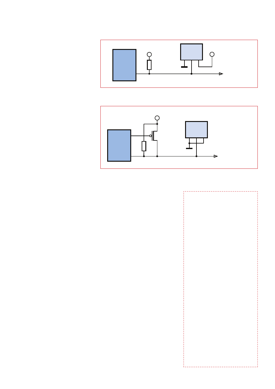
The two power supply options are
shown on the data sheet. You can either
use V
DD
(Figure 5) or transmit the sup-
ply voltage via the data bus (Figure 6).
The second option has the advantage
that, as already mentioned, you only
need two wires to connect the sensors
to the bus. The FET that is necessary
for connecting the bus to the supply
voltage of the microcontroller is already
present in the ATmega88. All that has
to be done is to configure the appro-
priate I/O pin as an output and set it
to the ‘high’ state. There are two situ-
ations where this is necessary. When
a temperature measurement must be
performed, the IC needs a bit of extra
power for 750 ms, and when data must
been downloaded to the flash memory
of the microcontroller, you’re ready to
go. The received data is transmitted
via the serial interface at 38,400 baud,
and the status of the network is shown
on the LC display (see Figure 4). The
BASCOM software does not drive the
display, but only sends the data to the
PC via the serial link.
Power supply
If you include the ground wire in the
count, the one-wire bus is a two-wire
bus. However, the DS1820 has three
leads, and you have to decide what to
do with the third lead (V
DD
). Many Dal-
las chips actually need only two leads
(data and ground), with the data lead
also serving as the power lead. This
is also true for the DS1820. However,
there are certain situations in which
the DS1820 sensor needs more current
than it can obtain with the usual pull-
up resistor value of 4.7 k . The options
here are to connect V
DD
to +5 V, which
means using a three-wire bus, or to
make a low-impedance connection
TO-92
(DS18S20)
1
(BOTTOM VIEW
080641 - 12
)
2 3
DALLAS
DS1820
1
GND
D
Q
V
DD
2 3
SO
(150 mils)
(DS18S20Z)
N.C.
N.C.
N.C.
N.C.
N.C.
GND
DQ
V
DD
6
8
7
5
3
1
2
4
DS1820
Figure 2. Pin assignments of the TO-92 and SMD versions.
LCD 20 x 4
+5V
080641 - 13
GND
DATA
CLK
2x DS1820
4k
7
1
1 = GND
2 = DQ
3 = V
DD
2
2
3
1
3
Figure 3. Wiring diagram showing the temperature sensors on the two-wire bus, the pull-up resistor and the LC display.
Figure 4. Find and seek.
51
3/2009 - elektor
be written to the internal EEPROM, it
needs more juice for 10 ms.
You can connect a single sensor or
several sensors. The software for the
arrangement with only one sensor is
different from the software for a bus
system. It is usually necessary to first
identify all the sensor ICs on the one-
wire bus so they can be addressed
individually. For systems with only
one sensor IC, Dallas has generated a
simplified protocol that works without
addressing. The first example in BAS-
COM is designed to use this simplified
protocol.
One wire, one chip
BASCOM code supports the one-wire
bus with special commands. This
means that you don’t have to do very
much; all you really have to do is to
decide which port pin to use for the
bus. You can select any desired pin,
and here we decided to use port D.5
(Config 1wire = Portd.5)
Every action is initiated by a bus reset
(1wreset). After this you can write
and read data. All of the details are
described in the data sheet [3]. In order
to communicate with a single IC, you
use the SKIP ROM command [CCh].
This causes the IC to regard itself as
addressed, even though its address
has not been mentioned. This is simi-
lar to the situation in a tiny village with
only one inhabitant: no house number
is necessary.
Next comes the temperature meas-
urement command CONVERT T [44h].
Immediately after this, the power sup-
ply must be switched on. Although
the bus is already at a ‘high’ level in
the idle state, this puts it in the low-
impedance ‘high’ state (Ddrd.5 = 1).
The maximum time necessary for mak-
ing a measurement is 750 ms. To be
on the safe side, you can always allo-
cate 800 ms for this state. After this
the port pin must again be configured
as an input (Ddrd.5 = 0). The DS1820
now knows the temperature, but it still
has to be read out. To do this, your first
send a Bus Reset and then the Read
Scratchpad command [BEh]. Up to
eight bytes can then be read from
the IC. The meaning of these bytes is
described in the data sheet (see Fig-
ure 7
). The temperature data is located
in two bytes, but the data in the high
byte only distinguishes between posi-
tive (00) and negative (FF) tempera-
tures. If you want to read the temper-
ature with higher resolution, you must
evaluate even more bytes. However,
this is not done in the first example.
For your initial testing in the lab, you
can assume that the temperature will
be positive. This means you only have
to read one byte, which contains the
temperature measurement in units of
0.5 degree. Simply divide the value of
the byte by 2 to obtain integer degrees.
Listing 1
shows a very simple program
that sends the temperature in degrees,
without any digits after the decimal
point, to the PC at 38,400 baud.
If you see a constant temperature of
85 degrees during your experiments,
there is something wrong with the
temperature conversion or the power
supply, since this is the default set-
ting after power-on before any meas-
urement is made.
Naturally, you can do more with the
temperature measurements than just
display them. Listing 2 shows a sim-
ple threshold switch with two levels.
Output D2 switches when the tem-
perature reaches 25 degrees, and out-
put D3 switches when it reaches 30
degrees. If you can’t think of any better
use for this, you can always use it with
two LEDs as a party gag. Have your
guests hold the sensor between two
fingers. With this simple instrument,
you can classify them into three types:
hot, lukewarm, and zombie.
V
DD
(EXTERNAL SUPPLY)
DS18S20
GND
V
DD
DQ
V
PU
080641 - 14
4k7
TO OTHER
1-WIRE DEVICES
1-Wire BUS
µP
Figure 5. Power supply via V
DD
.
Listing 1.
Temperature measurement
with one sensor
‘BASCOM-AVR
‘DS18S20 1 wire PD.5
$regfile = “m88def.dat”
$crystal = 16000000
$baud = 38400
Config 1wire = Portd.5
Dim Rom1 As Integer
Dim Temp As Integer
Wait 1
Ddrd.2 = 1
Ddrb.3 = 1
Do
1wreset
1wwrite &HCC
1wwrite &H44
Ddrd.5 = 1
Waitms 800
Ddrd.5 = 0
1wreset
1wwrite &HCC
1wwrite &HBE
Rom1 = 1wread(1)
1wreset
Temp = Rom1 / 2
Print Temp
Waitms 100
Loop
End
DS18S20
GND
V
DD
DQ
080641 - 15
TO OTHER
1-WIRE DEVICES
1-Wire BUS
µP
V
PU
4k7
Figure 6. Power supply via DQ.

PROJECTS
MICROCONTROLLERS
52
elektor - 3/2009
Several DS1820s on a single bus
Every one-wire IC has a 48-bit number,
and there are no two ICs with the same
number (at least not from Dallas). You
obtain this number by reading and
storing a total of eight bytes. You can
then use it on the bus as an address
for communicating selectively with a
particular IC. The ICs do not even have
to be the same type, since the type of
each one-wire IC is included in the
address (see Figure 8).
To start with, you can query how
many devices are present on the bus
(1wirecount). The Dallas bus protocol
specifies that all ICs report their ID
number at the beginning. BASCOM
use two functions, 1wsearchfirst() and
1wsearchnext(), to query them. An
array of eight bytes must be allocated
for each ID code:
Dim Id1(8) As Byte, Dim Id2(8)
As Byte
The example in Listing 3 is limited to
two devices on the bus. Simply to sat-
isfy our curiosity, we displayed the two
IDs on the PC. They both start with
‘10’, which is the ‘family code’ of the
DS1820.
The temperature measurement rou-
tine in Listing 4 first uses the non-
addressed mode to trigger a new
conversion. This means that all of
the temperature measurement ICs on
the bus receive the same command
and make their measurements at the
same time. After the 800-ms measur-
ing interval has expired, the ICs are
addressed individually and read out.
Addressing is performed by send-
ing the MATCH ROM command [55h]
followed by the eight ID bytes. This
can be done by sending the individ-
ual bytes in a loop, or all at once with
1wwrite Id2(1), 8. Sending an address
causes a particular IC to be selected.
Only this IC will respond to the readout
command. You can now read out a sin-
Listing 2
Dual-threshold switch
If Temp > 24 Then
Portd.2 = 1
Else
Portd.2 = 0
End If
If Temp > 29 Then
Portd.3 = 1
Else
Portd.3 = 0
End If
Listing 4
Measuring with two sensors
Wait 1
Ddrd.2 = 1
Ddrb.3 = 1
Do
1wreset
1wwrite &HCC
1wwrite &H44
Ddrd.5 = 1
Waitms 800
Ddrd.5 = 0
1wreset
1wwrite &H55
For I = 1 To 8
1wwrite Id1(i)
Next I
1wwrite &HBE
Rom(1) = 1wread(1)
Temp = Rom(1) / 2
Print Temp;
Print “ “;
1wreset
1wwrite &H55
For I = 1 To 8
1wwrite Id2(i)
Next I
1wwrite &HBE
Rom(1) = 1wread(8)
Temp = Rom(1) / 2
Tempdif = 16 - Rom(7)
Tempdif = Tempdif / 16
Tempdif = 0.25 * Tempdif
Temp = Temp + Tempdif
Print Fusing(temp , “#.##”)
Waitms 100
Loop
SCRATCHPAD
(POWER-UP STATE)
Byte 0 Temperature LSB (AAh)
Byte 1 Temperature MSB (00h)
EEPROM
Byte 2 T
H
Register or User Byte 1*
T
H
Register or User Byte 1
Byte 3 T
L
Register or User Byte 2*
T
L
Register or User Byte 2
)
h
F
F
(
d
e
v
r
e
s
e
R
4
e
t
y
B
)
h
F
F
(
d
e
v
r
e
s
e
R
5
e
t
y
B
Byte 6 COUNT REMAIN (0Ch)
Byte 7 COUNT PER °C (10h)
*
C
R
C
8
e
t
y
B
*
Power-up state depends on value(s) stored in EEPROM.
080641 - 16
(85°C)
Figure 7. ROM contents.
Listing 3
Using two sensors
04FF49801080033
106F0099010800B3
‘Atm18 DS1820 Bus
$regfile = “m88def.dat”
$crystal = 16000000
Baud = 38400
‘*******************************
‘BASCOM-AVR
‘DS18S20 1 wire PD.5
$regfile = “m88def.dat”
$crystal = 16000000
$baud = 38400
Config 1wire = Portd.5
Dim Rom(8) As Byte
Dim Temp As Single
Dim Tempdif As Single
Dim Id1(8) As Byte
Dim Id2(8) As Byte
Dim I As Integer
Id1(1) = 1wsearchfirst()
Id2(1) = 1wsearchnext()
I = 1wirecount()
Print I
For I = 1 To 8
Print Hex(id1(i));
Next
Print
For I = 1 To 8
Print Hex(id2(i));
Next
Print

7
3/2009 - elektor
gle byte, or all eight bytes at once in
order to increase the temperature reso-
lution (Rom(1) = 1wread(8)).
You can increase the temperature reso-
lution by evaluating the seventh byte
(COUNT REMAIN) of the set of read
bytes. It contains a value in the range
of 1 to 16, which must be interpreted
as sixteenths of a degree. However,
you must be careful here because the
least significant bit of the low byte
of the ‘regular’ temperature reading
(0.5 degree) is the same as the most
significant bit of the Count Remain
register. This means that you must first
round to whole degrees and then add
the sixteenths count.
The best possible resolution is thus
0.06 degree, so the result is displayed
with two digits after the decimal
point. Naturally, the final digit should
be treated with caution, since you
should always make a clear distinc-
tion between accuracy and resolution.
The actual accuracy is approximately
0.5
nC in the range from –55 nC to +
85
nC. However, the enhanced resolu-
tion makes it easier to recognise very
small temperature changes. If you hold
two sensors in close thermal contact
and compare their displayed readings,
you will see that the difference is usu-
ally less than 0.1
nC.
(080641-I)
[1] http://en.wikipedia.org/wiki/Temperature
[2] www.elektor.com/080641
[3] http://datasheets.maxim-ic.com/en/ds/
DS18S20.pdf
8-BIT CRC
48-BIT SERIAL NUMBER
8-BIT FAMILY CODE (10h)
B
S
M
B
S
M
B
S
L
B
S
L
B
S
L
MSB
080641 - 17
Figure 8. Chip address.
The ATM18 project at Computer:club
2
ATM18 is a joint project of Elektor and Computer:club
2
(www.cczwei.de) in collaboration with
Udo Jürsz, Chief Designer of www.microdrones.de. The latest developments and applications
of the Elektor ATM18 are presented by Computer:club
2
member Wolfgang Rudolph in the
CC
2
-tv programme broadcast on the German NRW-TV channel. The IR distance sensor and
ATM18-AVR board combination described here was featured in instalment 25 of CC
2
-tv.
CC
2
-tv is broadcast live by NRW-TV via the cable television network in North Rhine–Westphalia
and as a LiveStream programme via the Internet (www.nrw.tv/home/cc2). CC
2
-tv is also
available as a podcast from www.cczwei.de and – a few days later – from sevenload.de.
See your project in print!
Elektor magazine is looking for
Technical Authors/Design Engineers
If you have
a
an innovative or original project you’d like to share with Elektor’s 140 k+
readership and the electronics community
a
above average skills in designing electronic circuits
a
experience in writing electronics-related software
a
basic skills in complementing your hardware or software with explanatory text
a
a PC, email and Internet access for efficient communications with Elektor’s
centrally located team of editors and technicians
then don’t hesitate to contact us for exciting opportunities to get your project or feature article published.
Our Author Guidelines are at: www.elektor.com/authors.
Elektor
Jan Buiting MA, Editor
Regus Brentford, 1000 Great West Road, Brentford TW8 9HH, United Kingdom
Email: editor@elektor.com
Advertisement
Wyszukiwarka
Podobne podstrony:
wire chip SERWER POMIARU TEMPERATURY Z MAGISTRALĄ 1 WIRE
ATM18 Two wire LCD
ATM18 Brim Full Capacitive liquid level measurement
Measurements of the temperature dependent changes of the photometrical and electrical parameters of
ATM18 Bits on Parade An I2C bus tester
rejestrator temperatury 16 kanałowy 1 wire
Przedmiot PRI i jego diagnoza przegląd koncepcji temperamentu
STRELAU KWESTIONARIUSZ TEMPERAMENTU(1)
W5 Temperatura powietrza WWSTiZ
temperament
4 Temperament typy osobowosci
Temperamentalne uwarunkowania ryzykownych zachowań u kierowców
Czujniki temperatury cieczy chłodzącej
Aktywny,2 przewodowy czujnik temperatury
ATM18 Relay Board
bmw 3 ci blad temperatury parownika
bmw E36 regulacji temperatury nie dziala
więcej podobnych podstron