
The Indispensable
PC Hardware Book
Your Hardware Questions Answered
THIRD EDITION
Hans-Peter Messmer
JAUME
ADDISON-WESLEY
.
Harlow, England
l
Reading, Massachusetts
l
Menlo Park, California
l
New York
Don Mills, Ontario
l
Amsterdam
l
Bonn
l
Sydney
l
Singapore
Tokyo
l
Madrid
l
San Juan
l
Milan
l
Mexico City
l
Seoul
l
Taipei
,

Part 1
Basics
This chapter outlines the basic components of a personal computer and various related peripherals
as an introduction to the PC world. Though this chapter is intended for beginners, advanced users
would also be better prepared for the later and more technically demanding parts of the book.
1 Main Components
1.1 The Computer and Peripherals
Personal computer (PC), by definition, means that users actually work with their own
computer. This usually means IBM-compatible computers using the DOS, OS/2 or Windows
(NT) operating system. Mainframe users may wonder what the difference is between a PC and
a
terminal:
after all, a terminal also has a monitor, a keyboard and a small case like the PC, and
looks much the same as that shown in Figure 1.1. Where there is a difference is that the PC
contains a small but complete computer, with a processor (hidden behind the names
80286 or i486, for example) and a floppy disk drive. This computer carries out data processing
on its own: that is, it can process files, do mathematical calculations, and much more besides.
On the other hand, a terminal only establishes a connection to the actual computer (the main-
frame). The terminal can’t carry out data processing on its own, being more a monitor with poor
input and output capabilities that can be located up to a few kilometres away from the actual
computer. That a small PC is less powerful than a mainframe occupying a whole building seems
obvious (although this has changed with the introduction of the Pentium), but that is only true
today. One of the first computers (called
ENIAC,
developed between 1943 and 1946, which
worked with tubes instead of transistors) occupied a large building, and consumed so much
electricity that the whole data processing institute could be heated by the dissipated power!
Nevertheless, ENIAC was far less powerful than today’s PCs.
Because PCs have to serve only one user, while mainframes are usually connected to more
than 100 users (who are
logged in
to the mainframe), the impact of the lack of data processing
performance in the PC is thus reduced, especially when using powerful Intel processors. An-
other feature of PCs (or microcomputers in general) is their excellent graphics capabilities,
which are a necessary prerequisite for user-friendly and graphics-oriented programs like Micro-
soft’s Windows. In this respect, the PC is superior to its
Figure 1.1 shows a basic PC workstation. The hub, of course, is the PC, where you find not only
the above-mentioned processor but one or more floppy disk drives, hard drives, interfaces and
other devices. These are dealt with in some detail in Section 1.2. Because you can’t enter
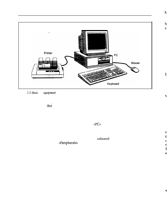
2
Chapter 1
Monitor
Figure
PC
commands into the actual PC, or receive data from it, a
keyboard
(for entering commands and
data) and a
monitor
data output) are also present. High quality computer monitors are far
more powerful (and therefore much more expensive) than a TV.
With this equipment you can start work: for example, entering text files, doing mathematical
calculations, or playing computer games. To use the PC’s graphics capabilities (with Windows,
for example) a mouse is usually needed. In this book,
always means the sum total of these
components, because without a keyboard and a monitor you can’t control the machine.
For printing text files, of course, you need a printer. By using various
interfaces you
can connect
additional
peripherals
like a
plotter
(for drawing plans with
pencils) or a
modem
(for world-
wide data communication).
means all those units located outside the PC’s case.
1.2 Inside the Personal Computer
This chapter deals with the various components of a PC, starting with basic definitions of
concepts like the motherboard, the controller etc; their functions are outlined. Also, an overall
picture of the interworkings between individual components is given.
1.2.1 How to Open the Case
To work with a PC or to understand how it works, you don’t, of course, need to open the case.
But I think there are a lot of curious users who will soon want to look inside. The following
gives some tips on doing this, while trying to avoid burnt-out electric components and rather
unpleasant electric shocks. To open the case you’ll need a screwdriver and some common sense.
It is best to use a magnetic screwdriver because, in my own experience, one or more screws will
inevitably fall into the case. With a magnetic screwdriver you can get
them
out quite easily.
r
r
t
I
I
I
I
I
I
1
I
,
1
1

Main Components
3
You may have heard that magnetic objects should never be placed near a PC. 1 would like to
comment on this:
the
has a magnetic field;
if you scratch your disk with a sharp object you do so at your own risk; it doesn’t matter
whether it is a knitting needle, a hammer or a magnetic screwdriver;
opening a hard disk drive means losing the data simply because of the dust that is always
present in the air; whether the hard disk is disturbed magnetically afterwards is completely
insignificant;
the distance between the read/write heads and the disk surface is less than about 1 pm.
principle, the Earth’s magnetic field is shielded by the PC’s metal case, but as soon as you
remove the cover the magnetic field penetrates all the components. As all electronic and mag-
netic components are exposed to the Earth’s magnetic field when the computer is assembled,
this obviously can’t have an adverse influence. Floppy and hard disks are coated with a thin
magnetizing layer: if someone deliberately scratches off this coating, he really doesn’t know
what he is doing. The data medium of the hard disk drives is enclosed in a case so that dust
particles in the air don’t act as a sort of scouring powder. Therefore, the hard disk is destroyed
not by magnetic but by mechanical action. Whether you are additionally damaging the still
present magnetic pattern with a magnetic object after the mechanical destruction of the data
medium would seem to be unimportant.
Finally, the distance between the read/write heads and the data medium is less than about
1 pm. Because of the protective envelope the closest you can bring the screwdriver to the data
medium of a floppy disk is one millimetre away at most. That is one thousandth of the
data medium distance. According to magnetostatic laws, the strength of the magnetic field
decreases in proportion to the square of the distance. This means that the screwdriver must have
a local field strength which is one millionth of the field of the read/write head. Perhaps someone
could show me this monster of a screwdriver with its superconducting magnet! In the case of
hard disk drives, this ratio is much greater because of the additional separation provided by the
drive’s case.
The dangers of mechanical destruction are clearly far more likely. I always use a magnetic
screwdriver because I always lose a screw in the case, and because of the danger of a short
circuit caused either by the screw or by a rash action after having tried to get the screw out.
Advice: If your case is sealed and there is a notice advising that breaking the seal will invalid-
ate the warranty, you should open the case only after having contacted your dealer.
Figure 1.2 shows three examples of PC cases (two desktops and one tower), which are the most
common types.
If you are one of those lucky PC buyers who got a technical reference book or at least a user
handbook when you bought your PC, you should have a look at this handbook first to find out
how to open the case. If you’ve found this information, then follow the manual and ignore the
next paragraph.
6
Chapter 1
devices the board is connected to. The individual components are presented below in greater
detail.
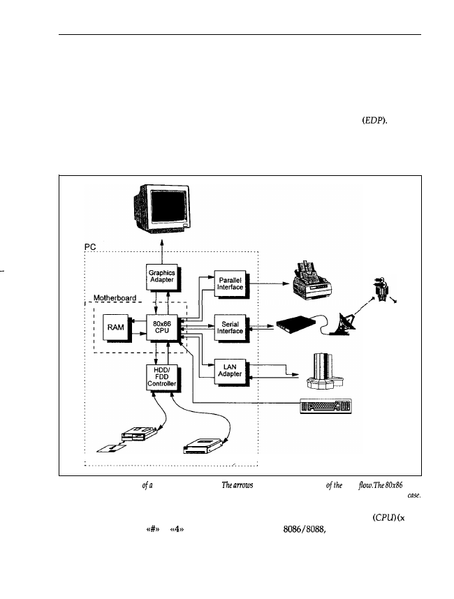
1.2.2 Data Flow inside the PC
Personal computers, like other computers, are used for electronic data processing
For this,
data must be input into the PC, and the PC has to supply (the resulting) data. Between input
and output, a varying amount of data processing takes place using a program. Figure 1.5 shows
a typical PC with the most important functional units necessary for data processing.
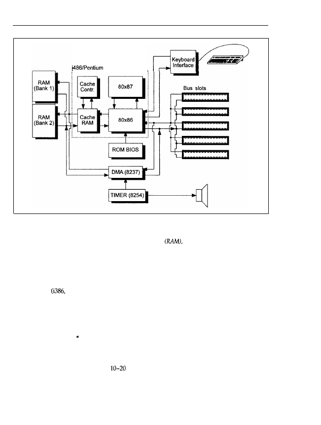
Figure 1.5: Block diagram
PC with peripherals.
indicate the direction
data
CPU
and the RAM are located on the motherboard. All parts surrounded by the broken line are normally inside the PC
The main part is the processor, also called the 80x86 Central Processing Unit
is a
dummy variable from
to
or Pentium to denote the
80186, 80286, i386, i486,
Pentium family of Intel processors used in IBM-compatible PCs). Because of the large number
of incoming and outgoing arrows, it can be seen that this processor represents (so to speak) the
heart of the computer, in which all data processing events take place. Immediately next to the
Main Components
7
CPU is the main memory, or Random Access Memory (RAM) that the CPU uses to store or read
intermediate results to or from data processing or programs. The CPU and RAM are the main
components of the motherboard. The processor is connected to the keyboard, with which you
enter data (text, for example) or commands (DIR, for example). To display such inputs visually,
the CPU is further connected to a graphics adapter, which accepts the data to display, and
processes it so it can be displayed on the monitor. At this point I want to mention that a
computer doesn’t necessarily need a monitor to output data; the monitor mainly supports the
user. There are a lot of computers (the engine control
for example) that are very
powerful, but which have neither a keyboard nor a monitor. In this case, the computer is usually
called a process computer. To read more extensive datasets, or to store them for a longer time,
and hard disk drives are included. The processor may read data from them or write data
to them with a controller. This is necessary because (apart from
and the main
memory of some laptops) all
lose their contents when the PC is powered down. All data
stored in that memory is thus irrevocably lost.
Nearly all PCs have at least one
interface (called PRN,
or
under DOS)
to which a printer may be connected, and at least one
interface (called
under
The serial interface is also often called the communication interface because a modem can
‘be connected to it, and with an appropriate program you can exchange data with other
via public telephone or data networks. For example, it is possible to access a database in
another country via satellite. In this way, your tiny (and seemingly unimportant) PC becomes
a member of an international data network. (You can see what unexpected possibilities a PC
offers beyond computer games!) Many PCs also have a network adapter, with which you embed
your computer into a
network (LAN), that is, you may exchange data with another or
computers that are also equipped with a network adapter. Nevertheless, the other com-
puter does not also have to be a PC. With your network adapter and appropriate software you
may easily access a supercomputer and start to work on it.
The Motherboard
the name implies, the motherboard is the heart of your PC, on which all components that
are absolutely necessary are located. Figure 1.6 shows a typical motherboard, though the layout
of motherboards may vary considerably. You can see the motherboard and several slots into
the circuit boards of the graphics adapter and the interfaces are located (the slots are
often called bus slots). If your motherboard has such bus slots but no further electronic com-
ponents, you have a PC with a so-called modular board. The motherboard in a modular PC is
into a bus board (which has the slots) and a separate processor board. The latter is inserted
a slot in the same way as all the other boards, but its internal structure is the same as the
described below. Figure 1.7 shows the motherboard in diagrammatic form.
As mentioned earlier, the 80x86 processor is the central unit of the board. It executes all the data
processing, that is, numbers are added, subtracted, multiplied or divided, logic operations with
items are executed (logical AND, for example) and therefore their relations (equal, above,
etc.) are determined, or data is input and output. For extensive mathematical operations
such as, for example, the calculation of the tangent of two real numbers with very high accuracy,
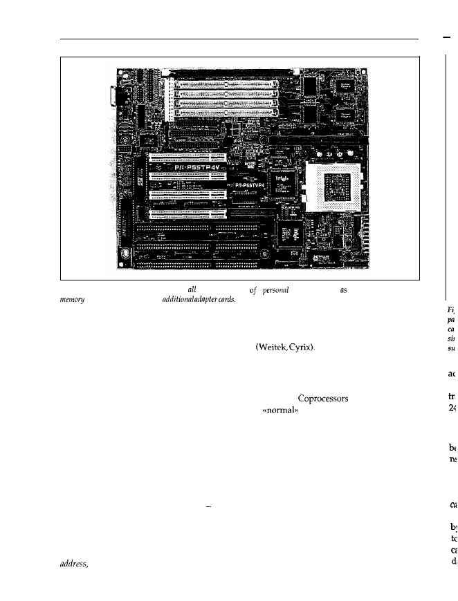
8
Chapter 1
M
Figure 1.6: The motherboard comprises the central parts a
computer, such the CPU, main
nnd extension slots for
a mathematical coprocessor or processor extension is available. Intel calls the coprocessors belong-
ing to the 80x86 family 80x87: for example, the 80287 is the coprocessor for the 80286 chip. Other
companies also supply mathematical coprocessors
Usually, PCs are not equipped with a coprocessor when shipped, only with a socket for it. You
can buy the corresponding chip afterwards and put it into this socket. The 80x86 automatically
recognizes whether a coprocessor is present, and transfers the corresponding commands to it;
the 80x87 then calculates the requested mathematical value.
may calculate the
tangent of an arc up to 100 times more quickly than
processors. So if you are doing
extensive mathematical applications (like, for example, three-dimensional computer graphics or
CAD) this gives an enormous advantage. The 486DX and its successors Pentium and Pentium
Pro already implement an FPU on-chip so that a coprocessor is obsolete. Only some 486DX
mother-boards have a socket for a Weitek coprocessor.
Another important motherboard component is the main memory or RAM. Usually, the RAM is
divided into several banks, though recently it has been made up of memory modules (SIMM or
SIP). Each bank has to be fully equipped with memory chips, meaning that the main memory
may only be extended bank-by-bank the memory of a partially equipped bank will not be
recognized by the PC. The lowest value for the main memory size of an AT-386 today is
4 Mbytes; fully equipped Pentium PCs have at least 32 Mbytes of RAM. The CPU stores data
and intermediate results, as well as programs, in its memory and reads them later. For this, the
processor has to tell the memory which data it wants to read (for example). This is done by an
which is something like the house number of the data unit requested. Transferring this
G
In
P’
se
A
a
m
Main Components
9
Figure 1.7:
Diagram of a motherboard. The diagram shows the typical structure of a motherboard. The central
part is the CPU 80x86. The CPU can be associated with an 80x87 coprocessor for mathematical applications and
cache controller and cache RAM to enhance performance. The i486 or Pentium integrates all these parts on a
single chip. Additionally, on the motherboard there are the memory
the ROM BIOS, the 8237 and 8254
support chips, a keyboard interface, and the bus slots.
address to the memory is carried out by an address bus, and the transfer of the data by a data bus.
Generally, in computer terms a bus means a number of lines through which data and signals are
transferred. Therefore, the address bus consists of several lines, in the PC generally 20 (PC/XT),
24 (AT) or 32
i486, Pentium) lines.
In the context of main memory you will often hear the expression access time. This is the time
period between the CPU’s command to the memory that data should be read and this data
being transferred to the processor. Modern memory chips have an access time of about 60-70
ns, which for humans is a minute time period (batting the eyelid takes at least one 100th of a
second, that is, 100 000 100 ns), but not so for modem computers with a high clock frequency.
Actually, the access time is one of the most important restrictions on the operational speed of
a PC. Therefore, powerful and fast-clocked computers (150 MHz and above) have a so-called
cache or cache memory. Usually, this cache is significantly smaller than the main memory, but
much faster (with an access time of
ns). The cache holds data that is frequently accessed
by the CPU so it is available to the processor more quickly. The CPU, therefore, doesn’t have
to wait for its relatively slow main memory. If the CPU reads data out of main memory, the
cache controller first checks to see whether this data is held in the cache memory. If it is, the
data is immediately transferred to the CPU; otherwise, the cache controller reads the data from

10
Chapter 1
the main
memory
and transfers it to the processor simultaneously. If the CPU wants to write
data it is written into the cache memory at a high speed. Later, the cache controller writes it into
the main memory. You sometimes demonstrate similar behaviour yourself; for example, if you
are programming some routines you take off the shelf those documents that you are likely to
need. In this case, your desk is the cache memory and you are the cache controller. When a
problem arises you take additional documents off the shelf and put them on your desk. If the
desk is full (the cache memory is exhausted) you put those documents you are unlikely to need
back on the shelf. Other documents that you need may then be placed on your desk. In these
circumstances it is important that the cache memory is transparent to the processor, that is, the
CPU doesn’t recognize that a fast cache memory is installed between itself and the main memory.
In other words, the processor operates as if no cache memory were present. On the new and
powerful 80x86 family processors, the processor, coprocessor, cache memory and a cache con-
troller are integrated on a single chip to form the i486 or Pentium.
The motherboard also includes a Read Only Memory (ROM). Located on this chip are the pro-
grams and data that the PC needs at power-up (because it loses the contents of its main memory
when
it is powered down). The processor reads these programs and executes them at
up. In the ROM there are also various support routines for accessing the keyboard, graphics
adapter, etc. known collectively as the ROM-BIOS. If you enter data via the keyboard, the
keyboard interface communicates directly with the processor (for advanced readers, it issues a
hardware interrupt; see Chapter
and informs it that a character has been input. The CPU
can then read and process that character.
As mentioned above, data is exchanged via the address and data buses. To control the data
transfer processes, additional control signals are required; for example, the CPU must tell the
memory whether data should be read or written. This is carried out by a so-called write-enable
signal, for which one bus line is reserved. Because of the various signals, the slot has, for
example, 62 contacts for the XT bus (the XT’s system bus) and 98 contacts for the AT bus. (Note
that the bus slots therefore have different lengths.) The lines for the control signals are guided
in parallel to the address and data buses and lead to the bus slots. The data bus, address bus
and all the control lines are known as the system bus, which ensures that all inserted adapter
cards are informed about all the operations taking place in the PC.
For example, a memory expansion card may be inserted in one bus slot. The CPU accesses the
memory on this adapter card in the same way as it accesses the memory on the motherboard.
Therefore, the bus slots must have all the signals necessary to control the PC components (and
this expansion card, for example, is one of them). Theoretically, it does not matter into which
free slot an adapter card is inserted, as long as all the contacts fit into the bus slot. In practice
(especially if you are using a low quality motherboard or adapter card), an adapter card may
only run correctly in a certain bus slot, as it is only in this bus slot that all the bus signals arrive
at the appropriate time. Frequently, extensive amounts of data must be transferred from a hard
or floppy disk into the main memory, as is the case when text is loaded into a word processor,
for example. For such minor tasks an 80x86 processor is too valuable a chip, because it can carry
out far more complex operations than this. For this reason, the motherboard has one (PC/XT)
or two (AT) chips optimized for data transfer within the computer the Direct Memory Access
chips. They are connected to the main memory and the data bus, and to certain control
Main Components
11
lines that are part of the bus slots. Using these control lines, the DMA chips can be activated to
carry out data transfer from a hard disk into main memory, for example, at a very high speed.
In this process the CPU is bypassed and is not allocated the data transfer operation.
You have probably realized that your PC can also be used as a clock, telling the date and time
(DOS commands DATE and TIME). To implement this function a timer
chip
is present, which
periodically tells the processor that the DOS-internal clock has to be updated. (This chip also
controls memory refresh and the speaker.) In a Dynamic RAM (DRAM), the information stored
vanishes as time passes (typically within a period of 10 ms to 1
To avoid this, the DRAM has
to be periodically refreshed to regenerate the memory contents.
are used in the PC as
main memory. Bus slots are vitally important in making PCs flexible. Besides the standard
in graphics adapters, controllers, etc., you can also insert other adapters, such as a voice synthes-
izer to program spoken output on your PC. This might be a first step towards a
multimedia PC.
1.2.4
Adapters and Monitors
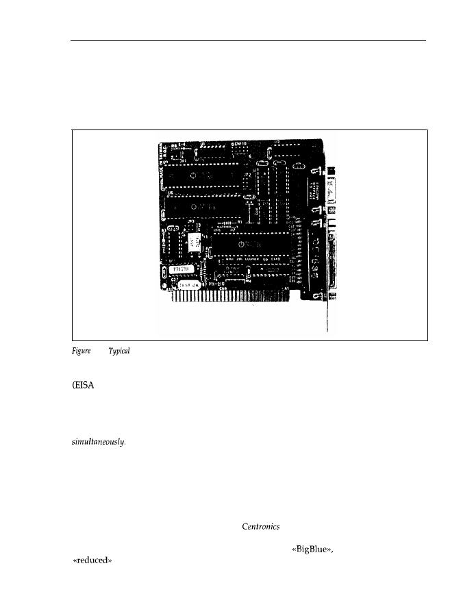
For a user, an essential part of a PC is the monitor, as well as the accompanying graphics or
display adapter card. Strictly speaking, a graphics adapter is electronic circuitry for displaying
graphics. A display adapter is the generic term, and it also includes electronic devices that can
only display text (that is, no free lines, circles etc.), though because text adapters are no longer
used in PCs, this strict distinction has vanished. The graphics adapter is usually constructed as
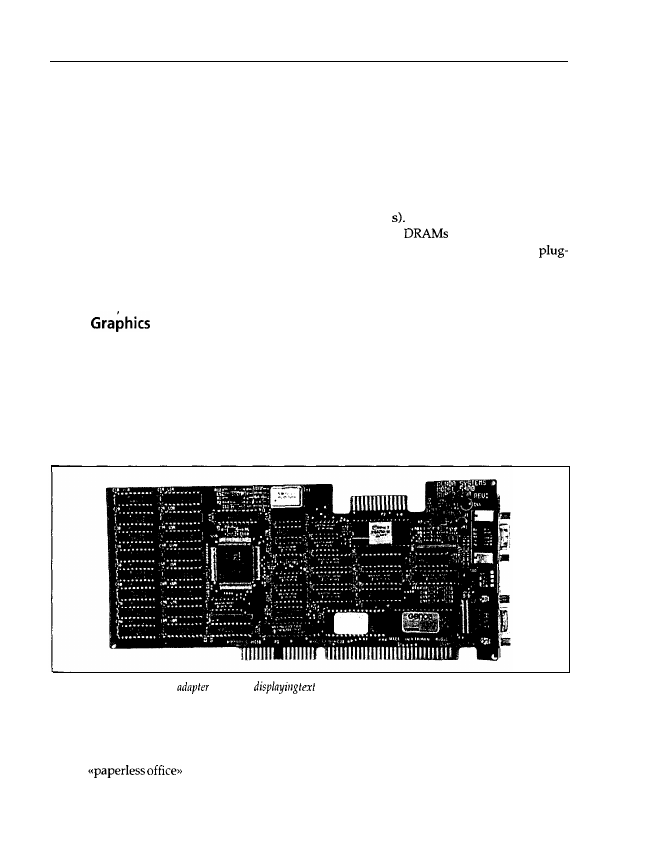
a plug-in card for a bus slot. Figure 1.8 shows a VGA adapter card.
Figure 1.8: A typical VGA
card
for
and graphics on-screen
Although it is possible to run a PC without a monitor and to output directly to a printer, this
is a painstaking process. If graphics are to be printed, a dot matrix printer is usually occupied
for several minutes, and a laser printer will be tied up for many seconds. Moreover, in the age
of the
it is inappropriate to output all draft documents to paper immediately.
Therefore the monitor, with its short response time and the vibrancy of its displayed data, is far
better as an output medium. If, for example, a line has to be inserted into a drawing, only this
new line has to be formed, not the whole displayed image. Under DOS, the monitor and the
12
Chapter 1
Graphics Adapter
keyboard are regarded as a single entity because of their special usage as standard input/output
devices, and are thus called the console (DOS-unit CON).
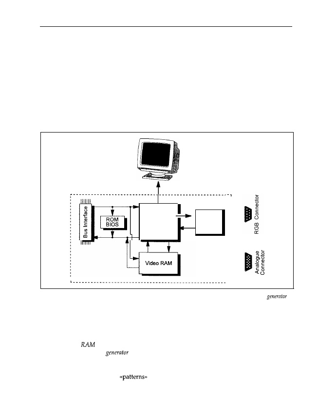
The hub of a graphics adapter is the graphics control chip, for example a Motorola 6845 or an S3
chip for accelerating the video output with Windows (Figure 1.9). You’ll find this, or a compat-
ible and more developed chip, on many adapters. It is responsible for driving the monitor, that
is, supplying pulses for horizontal and vertical retraces, displaying the cursor, controlling the
number of text lines and columns, as well as the display of text and graphics. The picture on
the monitor is written by an electron beam similar to that in a TV, which scans the screen line
by line. If the beam reaches the lower right comer, it returns to the upper left corner, that is, a
new page.
Graphic
Controller
Character
Chip (6845
Generator
or S3)
Figure 1.9: Graphics adapter. The central part is a graphics control chip, which controls the character
and the video RAM. The CPU can access the control chip and the video RAM via the bus interface.
The graphics adapter has two operation modes: text and graphics. Characters are displayed as
a fixed pattern of points, graphics as a free pattern. If a certain character is to be displayed in
text mode, the CPU
need
pass only the number or code of this character to the graphics control
chip. The video
holds data (codes) that determine the character to be displayed on-screen.
The job of the character
is to convert this code into a corresponding pattern of pixels
so that the character can be displayed on-screen by the graphics control chip. On the other hand,
in graphics mode the video RAM is read out directly and the character generator is not enabled.
Therefore, far more complex
(i.e. graphics) may be displayed.
The data for the screen contents is written into the video RAM by the CPU. The CPU may also
read data out of the video RAM, for example to determine the character at a certain location

Main Components
13
on-screen. For this the graphics adapter has a bus interface, which detects whether data for the
graphics adapter is present on the system bus. Via the bus interface, the CPU can write data into
the video RAM which, for example, is displayed as text on-screen. On the other hand, the CPU
may read data about to be overwritten by a new window under MS-Windows and store it in
main memory. It is thus possible to restore the original state by retransferring, after closing the
window, the data stored in main memory back into the video RAM. Moreover, the graphics
control chip can be reprogrammed via the bus interface so that, for example, instead of the usual
25 lines and 80 columns each, a new mode with 60 lines and 132 columns each is displayed.
Because reprogramming the graphics control chip from a standard mode to the mode mentioned
above is dependent upon the particular hardware on the graphics adapter, high-resolution
adapter cards have their own BIOS. This is located in a ROM, and supports the
BIOS on the motherboard. It includes routines to switch between different display modes (modem
graphics adapters may have up to 80 different such modes), to set points with a certain
at a certain location on the screen, or to use various pages in video memory. For this, the CPU
on the motherboard calls the corresponding program in the ROM-BIOS of the graphics adapter
via the bus interface.
On the back of the graphics adapter there are usually one or more jacks. Connectors for mono-
chrome and RGB monitors (red-green-blue) have two rows of holes; connectors for analogue
monitors have three rows. Monochrome and RGB monitors are driven by digital signals so that
a maximum of 16 different colours may be displayed simultaneously: two each for red, green
and blue, and an additional intensity signal (high, low). Therefore, 2“ = 16 different signal com-
binations are possible. With an EGA adapter card, these 16 colours may be chosen from a palette
containing 64 colours. This means that only 16 of these 64 colours can be displayed simultaneously.
The VGA card and other new adapters drive an analogue monitor with an analogue signal. In
principle, any number of colours may now be displayed simultaneously, but for technical rea-
sons the VGA standard limits them to 256 simultaneously displayable colours. The 256 colours
may be selected from a palette of 262 144 (64 red 64 green 64 blue) different colours.
resolution graphics adapters with a resolution of 1280 1024 points drive the correspondingly
more powerful monitors by an analogue signal, which is transmitted via a BNC cable. The cable
is shielded against external influences so that the driving signals are not disturbed and the cable
doesn’t act as an antenna and influence other equipment. Some graphics adapters have all three
jacks. On the Hercules and other compatible graphics cards, a parallel interface is integrated
onto the adapter card. You will see this if a jack for connecting a printer with a parallel interface
is present. Figure 1.15 shows the layout of the parallel interface jack.
1.2.5 Drive Controllers, Floppy and Hard Disk Drives
As already mentioned, the main disadvantage of main memory is the volatility of the stored
data. When the PC is switched off, or if the power supply is interrupted, all the data is lost.
Therefore, RAM is unsuitable for long-term data storage. For this reason, magnetic memories
were developed very early on. Before the invention and the triumphant progress of semi-
conductor memories and integrated memory chips, even main memory consisted of magnetic
drums. Later, these drums were replaced by magnetic core memories, tiny magnetic rings through
14
Chapter 1
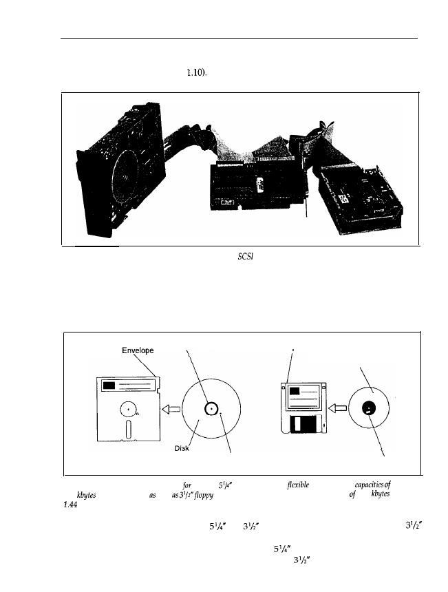
which run read and write wires. In the PC field, floppy disks and hard disk drives are now
generally established (see Figure
Figure 1.10: A typical floppy drive, hard disk drive and
con&controller.
Floppy disk drives belong to the group of drives with so-called removable data volume, because
different floppies (data volumes) can be inserted into a single drive and removed later. The
actual floppy disk is a circular and flexible disk, coated with a magnetic material and housed
in a protective envelope (see Figure 1.11).
Flexible
Hard Hole
Plastic Case
Disk
‘index Hole
Notch
Figure 1.11: Floppy disks. Presently the PC,
floppy
disks in a
envelope
with
360
and 1.2 Mbytes well
disks
in hard plastic cases
with capacities 720
and
Mbytes are available.
For IBM-compatible PCs, floppy disks
and
in diameter are available. The smaller
floppies are enclosed in a hard plastic case, and are inserted together with the case into the
drive, which writes data to it or reads data from it. On
floppy drives, the drive flap must
be locked down as otherwise no data can be read or written;
drives automatically lock the
Components
15
floppy disk in place. On the other hand, on hard disk drives or
disks the data volume cannot
be removed; it is fixed in the drive. Furthermore, the data volumes are no longer flexible, but
stiff
disks. Typically, a hard disk holds 1000 times more data than a floppy disk.
Floppy and hard disk drives are also used in other computers, such as the Apple Macintosh,
Commodore Amiga, or mainframes. Therefore, the technique of floppy and hard disk drives is
completely independent of the technology of a PC. To read and write data with the CPU on the
motherboard, it is necessary to control the drives. For this, a controller is inserted into one bus
slot to control the floppy and hard disk drives, and to transfer data between the drive and main
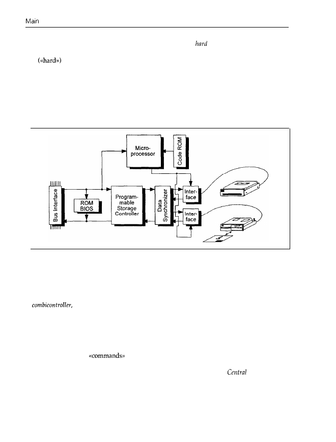
memory. Figure 1.12 shows a block diagram of a controller.
The controller is the link between the CPU and the drives. For this reason it has two interfaces:
the bus interface (which we met in the section on graphics adapters) for data exchange with
the CPU; and one interface for every floppy or hard disk drive. Today’s PCs usually have
a
with which two or more floppy drives and two hard disk drives can be
connected. The combicontroller has its own microprocessor, with programs stored in ROM to
control the electronic components on the controller card. To avoid any confusion, I must emphas-
ize that this microprocessor is not identical to the 80x86 CPU on the motherboard, but is sited
independently on the controller. Therefore, the controller is actually a small and independent
computer (a further example of a computer without a monitor), to which the CPU on the
motherboard supplies
via the bus interface. Similarly, you enter commands for the
CPU via the keyboard (interface). We shall meet this idea of independent, small computers that
support the central processor on the motherboard again,
hence the name
Processor Unit.
The microprocessor now controls data flow between the bus and drive interfaces by driving the
programmable storage controller and the data synchronizer appropriately. On floppy and hard
disks, the data is held in a form that is especially suited for data recording on these magnetic
data carriers. For processing in a PC this form is, however, completely unsuitable. Therefore,
the data synchronizer carries out a conversion between these two incompatible formats. The

16
Chapter
1
programmable storage controller controls the read and write operations, and checks the read
data for correctness.
To use and control the drives effectively, many controllers have their own ROM-BIOS. As for
the ROM-BIOS on a graphics adapter, this ROM-BIOS holds several routines for accessing the
hard disk controller. The control routines for the floppy drives are already located in the
BIOS on the motherboard do not confuse this ROM-BIOS with the ROM code. The routines
in the ROM code control the microprocessor on the controller and cannot be accessed by the
CPU on the motherboard, whereas the routines in the ROM-BIOS on the controller support the
CPU on the motherboard.
With intelligent drives like IDE, SCSI or ESDI, the controller is fixed to the drive so that drive and
controller together form an entity. Therefore, instead of a controller being inserted into a bus slot,
there is a host
adapter
in the slot; this host adapter establishes a connection between the system
bus and the controller. Usually, the host adapter has its own BIOS. In the mainframe field, the
actual computer is called
host and the user is connected to the host via a terminal.
Because a standard controller can be connected to many different drives, the controller has to
be constructed in a very general and simple way. A controller that is fixed to a certain drive,
however, may be adapted specially to that drive. Because of the low prices of today’s electronic
components, using a fixed controller (which requires one controller per drive) influences the
overall price only a little.
Some host adapters or controller cards have a jack on the reverse to connect an external drive.
SCSI adapters often have an additional jack on the back which directly connects to the internal
SCSI bus; thus external SCSI units may also be connected for example, an external streamer
drive can be used.
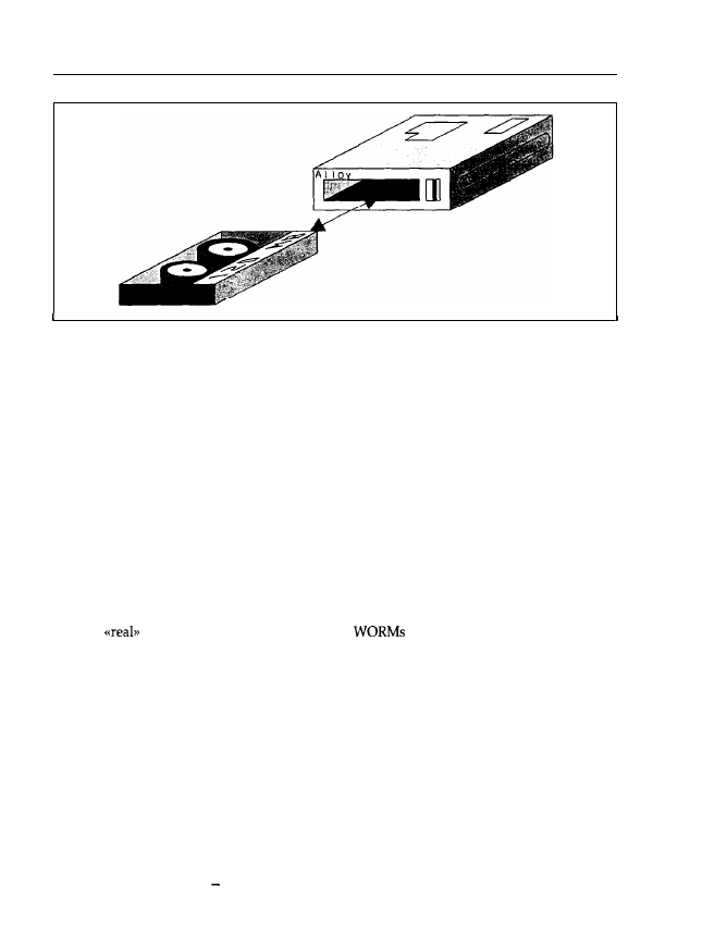
1.2.6 Streamers and Other Drives
Data backup is enormously important for users. Using floppy disks means spending a lot of
time on data backups because floppy drives are slow compared to hard disk drives; also, the
capacity of a floppy disk is roughly 100 times smaller than that of hard disks to back up a hard
disk of about 100 Mbytes capacity you would need 100 floppy disks. It is particularly frustrating
because almost every minute the filled floppy disk has to be removed and a new one inserted!
To overcome this restriction, and so that a qualified programmer is not occupied as a sort of
jockey,, streamer drives (streamers) were developed (see Figure 1.13). As the name indic-
ates, a regular streaming of data from the hard or floppy drives to a magnetic tape enclosed in
a streamer cartridge takes place. Magnetic tapes have been unbeatable up to now in view of
their simple handling, insensitivity, storage capacity and price, so they are well-suited for data
backup. The tapes used have an enormous storage capacity (up to several gigabytes) and are
enclosed in a highly accurate case. This virtually guarantees that the read/write head will be
able to locate the data tracks again later. Simple streamer drives may be connected to a floppy
disk controller. Very powerful streamers with a higher data transfer rate, on the other hand,
have their own controller, which is inserted into a bus slot and controlled by the accompanying
software, or have a SCSI interface. With such a system, a large hard disk can be backed up in
less than 15 minutes.
Main Components
17
Figure 1.13: Streamer drive and cartridge. In the PC
domain, tape
drives are used in the form of cartridge drives.
Such streamer cartridges have a capacity of up to 250 Mbytes.
In recent years, many other drive types and corresponding data carriers have come onto the
market, largely optical data volumes. They allow an even greater enhancement of storage capa-
city compared to high density hard disks. For distributing huge and unchangeable data sets
(like databases, program libraries, etc.), CD-ROM is especially well-suited. The name is derived
from the well-known CD player (Compact Disc), but instead of music signals, data is transferred
to the PC. In principle this is the same, as music can also be regarded as a data set. With only
one of these shiny CD-ROM disks, data that would normally occupy a large pack of floppy
disks can be shipped. The CD-ROM drive scans the surface of the disk with a laser beam and
converts the back-scattered laser light into a data stream. Depending on the technical design,
CD-ROM drives can be connected to existing floppy disk controllers or have a separate control-
ler that has to be inserted into a bus slot.
One big disadvantage with CD-ROMs is that data can be read but not modified. Progress
towards
optical data recording is offered by
(Write Once, Read Many). In such
drives, data may be written onto an optical disk once and read an infinite number of times
afterwards. If a data record is to be modified it must be written in the modified form at another,
free location. The original data remains on the disk but will be ignored. You can imagine that
the disk will fill within a short time, and
will
have to be replaced quite soon.
One relic of the PC’s ancient past should be mentioned: the cassette recorder. The first PC was
delivered by IBM in 1980 without a floppy drive but with a cassette recorder! This, of course,
had a specially adapted interface so that the CPU could read and write data. When loading a
program from the cassette recorder, which today’s hard drives carry out within a second, the
user could go out for a cup of coffee. Not least because of this, office work today has become
much more hectic.
Obviously the bus slots allow an enormous flexibility of expansion for your PC. In principle,
such seemingly exotic components as magnetic bubble or holographic memories can also be
embedded into your PC but by doing this you would already be crossing into the next
Century.
18
Chapter 1
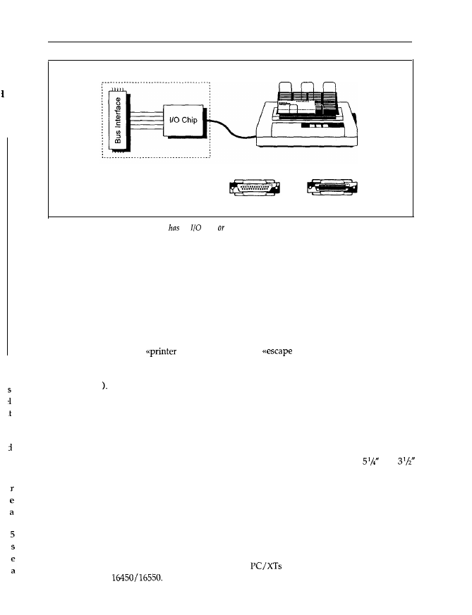
1.2.7 Parallel Interfaces and Printers
A PC is equipped with at least one parallel interface, which may be located on the motherboard
or on a separate interface adapter card (see Figure 1.14). On a separate interface adapter card,
in most cases, you’ll find an additional serial interface.
1.14:
interface adapter card on which a parallel interface and a serial interface are integrated.
Via the system bus, data is transmitted in units of one (PC/XT), two (AT bus) or four bytes
bus, 32-bit microchannel, Local Bus). The bus interface (see Figure 1.15) of a parallel
interface is therefore always one byte (or eight bits) wide. This means that one byte (or eight
bits) is transferred to the interface at a time (also true for graphics adapters, hard disk con-
trollers, serial interfaces, etc.). They are supplied with data in units of one byte. In the case
of a graphics adapter for the 32-bit EISA bus, for example, four such units may be transferred
On the other hand, a graphics adapter for the S-bit XT bus must be supplied with
four such units in succession.
The I/O-chip on the interface card accepts these eight bits together and transfers them together
(that is, in parallel) to the connected device (usually a printer) so that eight data lines are
present. Besides this data byte, control signals are also transmitted to indicate whether the data
has arrived. Up to 100 kbytes of data can thus be transferred every second if the parallel inter-
face and connected peripheral hardware is correctly adapted. On the interface is a jack with 25
holes, which supply signals according to the
standard. The standard actually claims
36 contacts, but the PC occupies only 25: the remaining 11 were not used by IBM, and are
therefore omitted. Because all manufacturers orient to
in time this has led to a
standard with only 25 contacts.
Main Components
19
e
h
Parallel Interface (LPTI. . ..)
Centronics Connectors
(Computer)
(Printer)
Figure 1.15: A parallel interface card an
chip an equivalent circuit that transmits or receives data at
the contacts
of
the Centronics connector to or from a printer.
You should be able to recognize a parallel interface by this jack, if in doubt. The disadvantage of
the Centronics standard is that cables with individual shielded wires are not used. The maximum
distance between the PC and printer is therefore limited to about 5 m. Of particular importance
is that the data is exchanged via handshaking, that is, the receiver confirms the reception of every
data byte, and a clock signal (strobe) is transmitted together with the data signals.
The printer accepts the transmitted data and prints the corresponding text or graphics. In doing
this, it generally responds to certain data patterns in the received data stream. In particular, it
checks whether so-called
control characters> or
sequences> are included, which
indicate a control command for the printer. The printer then reacts accordingly. For example,
the character sequence Odh Oah
means a
carriage return and line feed (CR = Carriage Return,
LF = Line Feed
Other peripherals may also be connected to a parallel interface, assuming that the receiving
interface satisfies the Centronics standard. Usually, the parallel interface only supplies data, but
doesn’t receive any. Actually, the older I/O-chips of parallel interfaces are unable to receive
data, but more recently, versions of these chips can receive data, and it is thus possible to
exchange data between computers via the parallel interface (and suitable software). IBM uses
this method in its F’S/2 series to transfer data between computer systems with
and
floppy disk drives, because their floppy formats are wholly incompatible.
1.2.8 Serial Interfaces and Modems
As well as a parallel interface, a PC usually has one or more serial interfaces. These are inte-
grated on an interface adapter card together with a parallel interface (see Figure 1.14). Figure
1.16 shows a diagram of a serial interface.
The central component is a so-called UART. Older
have an 8250 chip; the AT has the
more advanced
Via the bus interface, the CPU on the motherboard may access the
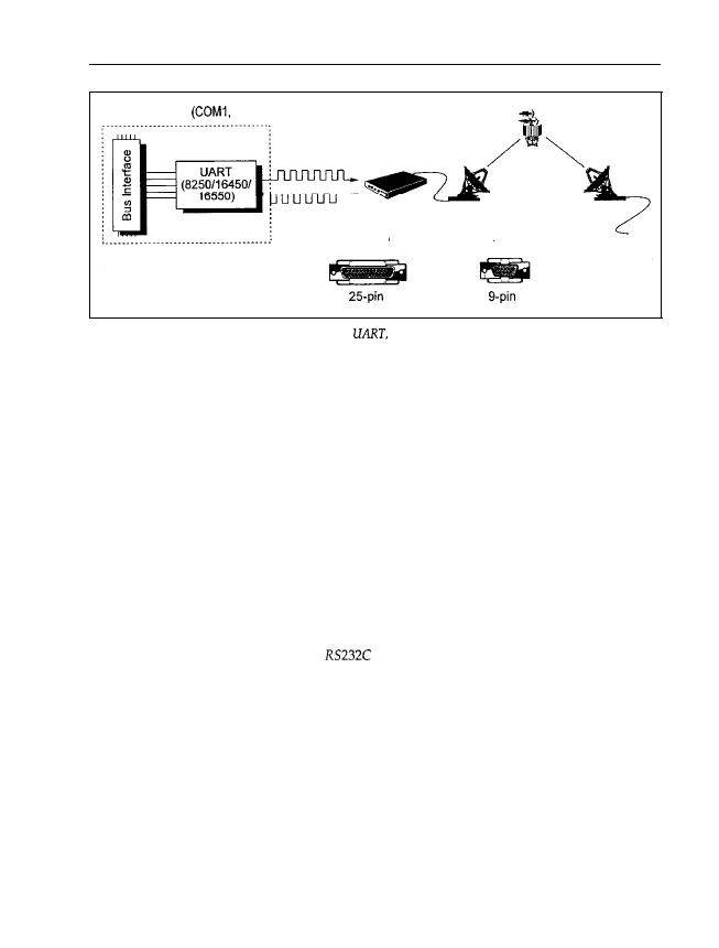
20
Chapter
1
Serial Interface
. ..)
RS-232C Connector
Figure 1.16: The serial interface largely consists of a
which executes the transformation to or from serial
data. With a serial interface a modem for data communications can be connected, for example. The PC has a serial
port with nine or 25 contacts.
UART and read or transmit data. In the case of a serial interface, like the parallel interface, data
is transferred to the bus interface, and from there to the LJART, in units of one byte. Unlike the
parallel interface, however, the UART doesn’t transfer the data to the peripheral in a parallel
way, but converts each byte into a serial stream of individual bits. This stream is transmitted
via a single data line, not eight as is the case for the parallel interface. Moreover, the UART adds
additional bits, if necessary: start, stop and parity bits. A data packet consisting of eight data bits
and the additional UART control bits is thus formed. The number of signal changes per second
is called the baud rate. The parity bit serves as a simple validity check for the transmitted data.
In this way, much longer distances compared to the parallel interface are possible (up to 100 m
without signal amplification). Moreover, the cable between the serial interface and any peripheral
is more convenient, as only one data line is present. However, the transfer rate is therefore lower
(in a PC up to 115 200 baud). Unlike connection via the parallel interface, no synchronization
signal is transmitted.
Serial interfaces in PCs conform to the
standard, which defines the layout and meaning
of the connections, and which requires 25 contacts. However, serial interfaces in PCs only
occupy 14 at most, even if the corresponding plug has 25 pins. Additionally, a reduced version
with only nine pins exists, but this is sufficient only for use in PCs defined by IBM. Note that
the contacts on the reverse of the interface adapter card are, unlike the parallel interface, formed
into a plug (that is, there are pins, not holes). You can thus easily tell serial and parallel inter-
faces apart.
One feature of UART, and therefore of the serial interface, is that the transmission and reception
of data may take place asynchronously. If data is arriving, the UART is activated without inter-
vention from the CPU, and it accepts the data. Afterwards, it tells the processor that data has
been received and is to be transferred to the CPU. If you connect a modem to your serial
interface (also called the communications inferface, COM), you can exchange data with other
computers of any size via the public telephone or data networks (your friends PC, or the com-
puting centre of a database service provider, for example). Your PC then behaves like a terminal
Main Components
21
that may be up to 20 000 km (or taking into account satellite transmissions, up to 100 000 km)
away from the actual computer. In this case, data is sent to the UART by the CPU in your PC.
The UART converts it into a serial bit stream and transfers the stream to the modem. In the
modem a carrier signal is modulated and transmitted via the telephone network and satellite to
another modem, which is connected to the destination computer. That modem demodulates the
signal (hence the name modem,
extracts the data, and transfers
it as a serial bit stream to the UART of the destination computer. The UART accepts this bit
stream, converts it into one byte, and transfers that byte to the destination computer’s CPU. If
that computer is to supply data to your PC, the process works in the opposite direction. This
only works, of course, if the transmission parameters (baud rate, number and values of start,
stop and parity bits) of your serial interface and the destination computer coincide.
Because data reception may take place asynchronously (that is, the UART need not know that
data is arriving at
GMT), a communications program may run in the background. There-
fore, you may, for example, input text while your PC is transmitting a message or receiving an
image. Using the serial interface, a simple local area network can be made to exchange small
amounts of data among several PCs. This method is popular for transferring data between
laptops and
PCs (Laplink, for example, does this).
I should mention that a serial interface often connects a mouse, trackball or a joystick to the PC.
If the user changes the position of these devices they output a serial data stream to the UART,
like a modem. The I-JART accepts it and supplies the data byte to the CPU. Because of the rather
long distances (compared to the parallel interface) that can be spanned with a serial interface,
devices in another room or even another building may be driven. Nevertheless, the data trans-
mission is very reliable, especially at low baud rates.
1.2.9 Network Adapters and
The basic concept of the PC was to put an individual computer at every user’s disposal. At
that time (planning started in the mid
the PC was (according to today’s standards)
very expensive, and a method of mass storage of extensive databases beyond most users’ means.
This led to typically only one computer being present in an office, and much work was done
manually or with a typewriter. Problems of data exchange could not arise because all data
was managed on this single computer. As the price of PC hardware rapidly decreased and
very powerful programs for word processing, databases, etc., appeared, the PC replaced manual
and typewriters more and more, leading to the introduction of innovative methods (like,
for example,
CAD
in the field of architecture or engineering). According to Figure 1.1, every
user would get their own printer and modem. That is, of course, a pure waste of resources,
as a laser printer, for example, is more expensive today than the PC
out of order for
more than 90% of the time!) Moreover, the data cannot be managed centrally, resulting in data
chaos. As a pure typewriter, a PC is far too good. Instead, its use for data processing and data
exchange with other PCs is unavoidable.
For this reason, local
networks
are being used more and more. As the name implies,
computers are networked locally (within a room, building or area) so that data (text files,
database records, sales numbers, etc.) may be interchanged among individual PCs. The central
Part of a LAN is the
server (see
Figure 1.17).
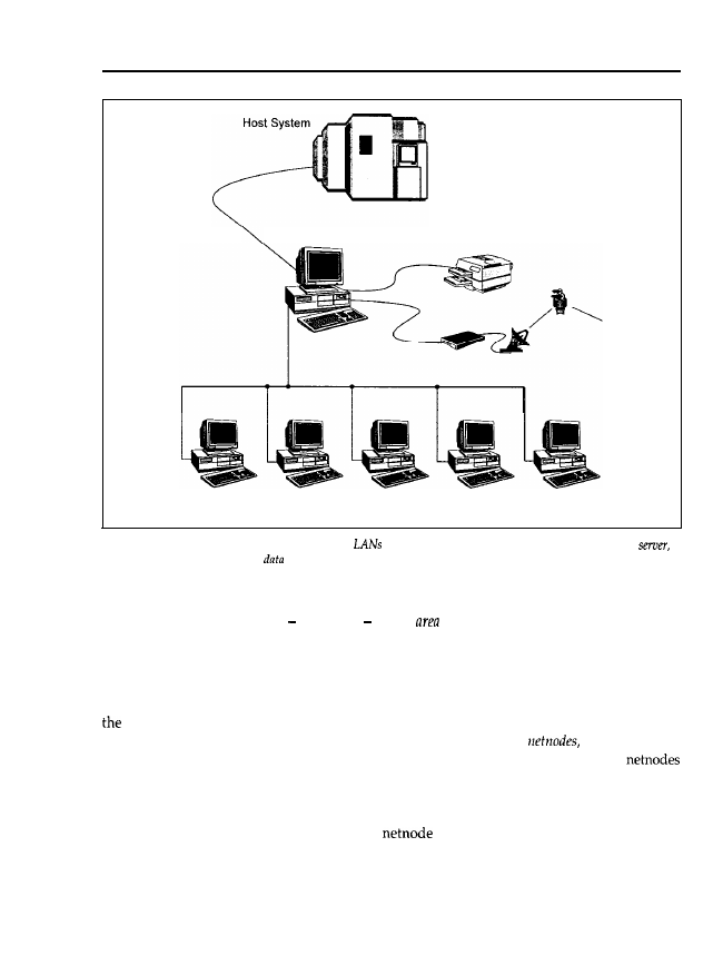
22
Chapter
1
LAN
Server
LAN Printer
Workstations (Net Nodes)
Figure 2.27:
Structure of a local area network.
are locally bounded. The central part of a LAN is a
which manages all the common
of all the network nodes, and establishes connections to peripherals or other
computers.
The counterpart of a LAN is what else a wide
network (WAN). Computers are thus
networked over long distances, for instance, the new passenger booking system AMADEUS
with which you can reserve airline tickets all over the world. The AMADEUS computer centre
is located in Erding, near Munich, with network nodes on all five continents.
On the server, all data which is accessible by more than one user is managed centrally. For this,
server has a high-capacity hard disk drive on which to hold all the data. Via cables and
network adapters, data may be transferred from the server to the
that is, the PCs
connected to the server, and vice versa. Moreover, a data exchange among the individual
is also possible. Therefore, it is no longer necessary to copy the data onto a floppy disk, carry
the floppy disk to the destination PC, and restore the data there. With a network, data can be
transmitted from your workstation to one or more destinations, as over a pneumatic dispatch
system. You can also fetch data from another
via the server. Unlike working on a PC,
which doesn’t usually have any password protection against illegal access, in a network you
need an access entitlement to be able to read or write certain data.
One particular advantage of the network as compared to a terminal is when the central com-
puter (here the server) fails: with a terminal you are brought to a complete standstill, but as a
Main Components
23
user in a LAN you can go on working with your own, local PC. A further advantage is that on
the server, all common data is managed centrally (and is backed up in one go there). Your
personal data stock is at your disposal on your own PC. Therefore, a maximum of data security
(by central management and backup) and, on the other hand, a maximum of flexibility, is
possible. Usually, all netmembers share one or more printers so that considerable savings are
possible, and the printer works to capacity. You may also exchange data via the server, so only
one telephone line is required.
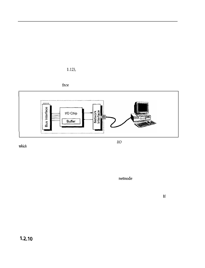
Like a controller (see Figure
a network adapter also has two interfaces: one bus interface
for connection to the PC’s CPU, and a network interface for accessing the network (see Figure
1.18). Like any other extension adapter card (graphics adapter, controller), the network adapter
may be inserted into any
bus slot.
LAN Adapter
Figure 1.18: A network adapter card has a (more or less) complicated
chip, which normally has a buffer in
to temporarily store
incoming or outgoing data. The network interface depends on the network used, e.g.
Ethernet or Token
Ring.
The CPU on the motherboard transfers data and commands to the I/O chip or buffer memory
on the network adapter card via the bus interface. This I/O chip converts the data into a form
that is adapted for transmission via the network, and it supplies the data to the network interface.
The network now transfers the data to the intended computer (server or netnode). If, on the other
hand, a command for transmitting data to the server or a
arrives at the I/O chip, the
command is placed into the buffer memory and the CPU is informed about it at a suitable time.
The CPU interrupts the ongoing process (the calculation of a mathematical expression, for
example), carries out the requested enquiry, and then restarts the interrupted process. the bus
interface for a PC on the network adapter card is replaced by an interface for another kind
of computer (a UNIX machine, for example) and you insert this newly set up adapter card in
the other computer, very different computers may be networked. Any computer can thus
be accessed via a network adapter, as is the case with a serial interface and a modem. Because
network adapters are much more powerful (the data throughput is up to 100 times higher), the
data is much faster.
CMOS RAM and Real-time Clock
From the previous sections you can see that a PC may be equipped with an endless variety of
expansion adapters such as graphics adapters, hard disk controllers, interfaces, etc. If the computer
24
Chapter
is switched off, the PC loses its memory, and therefore doesn’t know what components are
installed. At power-up, all drives and components must be initialized, that is, set to a defined
start-up state. You can imagine that there is a significant difference as to whether a 10 Mbytes
or 3000 Mbytes hard disk drive, or a main memory with 256 kbytes or 32 Mbytes, is present at
initialization.
In the first PCs and
the configuration could be set by different positions of so-called DIP
switches (see Figure 1.19). At power-up, the processor reads the switch positions and determines
which drives are installed and how much main memory is available. Because these switches are
located on the motherboard, they are often hidden by expansion adapter cards, so it is difficult
to make new settings.
Figure 1.19: DIP switches. On adapter cards or the motherboard you often find small DIP switches. These are
used to configure the adapter card or the motherboard.
Beginning with the AT, this information was then held by a chip on the motherboard, the CMOS
RAM (see Figure 1.6). The feature of this chip is that it needs relatively little power compared
with other memory chips. In
and all newer IBM-compatibles, a battery or accumulator is
present to supply power to this CMOS RAM (see Figure 1.20).
Figure 1.20: Battery and accumulator. Today’s PCs generally have a battery or an accumulator to back up the
configuration data of the CMOS RAM when the PC is switched off, and to periodically update the internal
real-time clock.
But the CMOS chip has another function: it includes a
real-time clock (see
Figure 1.21). When the
PC is switched off (or even unplugged) this clock is powered by the battery or accumulator, and
is therefore able to update time and data independently. Today you don’t have to provide the
time or date at power-up, as the computer reads the CMOS RAM (where, in addition to the
configuration data, the time and data are stored), and sets the DOS-internal system clock auto-
matically. A correct system time is necessary because DOS appends a time mark to all files,
Main Components
25
MC146818
- . - - . - . - . -
Figure 1.21: CMOS RAM and real-time clock. The PC has an MC746818 chip which has real-time clock and a
battey buffered CMOS RAM in which to store the configuration data.
indicating the time and date of the last file change.
Backup programs like BACKUP may use this
mark to determine which data to back up.
The CMOS RAM and real-time clock are integrated on a single chip, Motorola’s MC146818 or
compatible. The CMOS RAM usually has 64 bytes, and works for two or three years with one
battery.
1.2.11 Keyboard
The keyboard has remained the most important input device despite advances in
oriented user shells (such as Windows or SAA standards). Figure 1.22 shows an opened MF II
keyboard.
Like the controller, the keyboard is also a small
specialized for the conversion of
key hits into a bit stream (Figure 1.23).
The main part of the keyboard is a microprocessor (8042 for PC/XT and 8048 for AT and MF
II keyboards). This supervises the so-called scan matrix of the keyboard, which is made up of
crossing lines each connected to the keyboard processor. At the crossing points, small switches
are located, and on every switch a key is fixed. If you press a key the switch closes a contact
between the crossing lines of the scan matrix. Now the microprocessor can determine the coord-
inates of the pressed switch, and therefore the activated key. This is done in the form of a
which is transmitted via a buffer to the keyboard interface on the motherboard; thus the
knows which key has been pressed. Conversion of the scan code into the corresponding
character (letter A in Figure 1.23) is carried out by a program called the keyboard
driver
(in the
case of DOS,
Using this method, a lot of different keyboard layouts may be realized:
without needing to change the keyboard hardware, and especially the scan matrix, keyboards
for various languages can be realized simply by adjusting the keyboard driver for the language
concerned. With DOS you may choose American (US), British (UK), German
etc. keyboards.
.
26
Chapter
Figure 1.22: An opened
keyboard. You can see the
chip, the scan matrix and the small switches at
the crossings of the matrix.
Keyboard
Figure 1.23: The keyboard has a keyboard processor to supervise the scan
and a buffer in which to store
the characters. The characters are
to the keyboard interface on the motherboard. Programmable
keyboards can also receive data from the motherboard.
1.2.12 Mice and other Rodents
With the advance of graphic-oriented user shells, so-called pointing
devices
have become more
important. For the operation of many programs (Windows) they are very useful or even neces-
sary (for example,
The oldest pointing device is the mouse, so called because of its
plump body and long tail. Usually, a mouse is connected to the serial interface of the PC, but
there are versions with their own adapter card for a bus slot, so-called
bus mice.
Originally,
Microsoft planned three buttons for the mouse, but only two were used. Therefore, many mice
Main Components
27
have only two buttons. Well-known compatible mice are manufactured by Genius, Logitech and
other companies.
The mouse is of no use on its own: to move the
pointer (usually an arrow or rectangle
screen), every mouse needs (like the trackball or tablet) a program called a mouse driver. This
converts the signals from the mouse into commands for the CPU on the motherboard. The CPU
then drives the graphics adapter so that the pointer is actually moved. As you may already have
seen from looking at the outside, the mouse includes a ball coated with plastic or rubber. Figure
1.24 shows the inside of a mouse.
Figure 1.24: An opened mouse, with the
nnd photosensor
for
movement
The
ball is in contact with two small rollers. When you move the mouse the ball is rotated, and
the movement transmitted to the rollers. At the other end of the roller axis a disk with small
holes located at regular distances is fixed. On both sides of the disk there is a transmitter and
a receiver photosensor assembly. When the rollers are rotated by the ball, the disk interrupts the
photosensor assembly and opens it, depending on whether a hole in the disk is located between
the transmitter and receiver of the photosensor assembly. The number of such interruptions is
proportional to the number of ball rotations, and therefore to the distance the mouse is moved.
Because the two rollers are located perpendicular to each other (thus constituting a Cartesian
coordinate system), any oblique movement of the mouse is converted into two numbers by the
mouse’s electronic controls. These describe the number of interruptions and openings of the
Photosensor assembly for both disks, thus the mouse knows exactly how far it has been moved.
the values are transmitted via the cable to the serial interface, which then transfers the
values received to the CPU.
28
Chapter 1
In addition to this kind of mouse there are
mice that transmit the signal via an infrared
signal (similar to the remote control of a TV) to a receiver. The receiver is connected to the serial
interface or an adapter card. Moreover,
optical mice
have recently come onto the market. These
don’t have a ball, but determine the direction and amount of movement using the pattern on
a special
pad on which they are moved. In contrast to the rollers of a conventional mouse,
the sensors necessary for this don’t wear out, and because of the loss of the iron ball they are
lighter. The optical pattern is converted into a number by the mouse’s electronics, which rep-
resents the direction and the amount of movement. This conversion is rather complicated, and
requires more expensive electronic equipment, therefore optical mice are, unfortunately, far
more expensive than mechanical ones. If you put a mouse onto its
you virtually get a
Actually, the interior of a trackball is very similar to that of a mouse, but in general the
ball is considerably larger. You can rotate this ball in different directions with your fingers, and
thus move the mouse pointer on the screen. In some keyboards and notebooks the trackball has
already been integrated. For professional CAD and graphics applications a tablet is recom-
mended. Here, conversion of the tracking movement into pointer movement on-screen is executed
purely by electronics. Below the surface of the tablet there is a matrix made of wires through
which run current pulses. These pulses are detected by a magnifying glass and delivered to
the PC. The advantage of this matrix is the very high resolution. A high-quality mouse reaches
up to 400 dots per inch
a tablet, on the other hand, reaches 1000 dpi. Because the CPU
knows exactly where each pulse is at what time, the CPU can determine the exact position of
the magnifying glass on the tablet using the time at which the magnifying glass supplies a pulse.
Unlike the mouse, which may be placed anywhere on the desk and only returns the direction
and the amount of its movement, the tablet returns the absolute position (or coordinates). Usually,
a tablet is divided into a central part, which serves as a drawing area, and a peripheral part,
where symbol fields are located. The symbol fields depend on the application
for
example). If you click on a point in the drawing area,
draws a point. If, on the other
hand, you click a symbol field in the peripheral area,
executes a certain command
(which is symbolized by the field). There are further pointing devices such as the joystick, with
which you may move a pointer on-screen similar to the mouse. Another, older pointing device
is the so-called light pen. This takes the form of a pencil with which you can ‘press’ certain
optical keys or draw lines on the screen. The light pen works in a similar way to a tablet, but
here no electrical pulses run through a wire matrix. Instead, the light pen detects the light-up
of the screen at that position where the electron beam of the monitor hits the screen surface.
Therefore, the light pen (or better, the graphics adapter) can determine its location (line, column)
on the screen. As a user, you do not recognize the light-up as the eye is too slow. Another
pointing device is the touchpad: here, the movement of your finger over the touch-sensitive
surface of the pad is converted into a corresponding cursor movement on the screen. Touchpads
are often used for notebooks because they are very space-saving but work precisely.
1.2.13 The Power Supply
Of course, the components described above have to be supplied with energy in some way.
Therefore, the power supply is explained here in brief. Figure 1.25 shows a standard power
supply. (Depending on the computer manufacturer, there are many different shapes, of course.)
Main Components
29
Figure I
The power supply,
Usually, the power supply has one or two plugs for the motherboard, through which the
motherboard is supplied with the necessary power. Adapter cards connected and inserted into
the bus slots are usually supplied via the bus slots. Because the floppy and hard disk drives
require far more current (power dissipation of
W each), the power supply additionally
has up to four equal wire groups with appropriate plugs for the drives. Power supplies also
include a thin wire with a further plug for the motherboard, through which the so-called
good signal is transmitted to an electronic switch on the motherboard. The signal indicates that
all necessary voltages are stable after power-up. A low voltage may lead to undefined states in
initialization of the memory chips or the CPU, and therefore to disastrous failures. Thus, the
electronic switch releases the 80x86 processor only if the power supply signals a stable voltage
with the power-good signal. Not until then does the CPU call the
to initialize all chips and
boot the PC. The usual supply voltages in a PC are
V and
V. Some power supplies also
include a socket for inserting the monitor power cable, but bigger monitors with a correspond-
ingly higher power dissipation are usually plugged into their own socket.
1.3 Documentation
A very poor aspect of personal computers, especially of compatible products bought from the
smaller shops, is usually the low-quality documentation. As a respectable PC user you have, of
course, got a licensed operating system (MS-DOS, PC-DOS or Windows, in most cases). Along
with this
you normally get a detailed description of the system commands and, in most
cases, a BASIC interpreter or compiler (like GWBASIC,
or Quick Basic). Any hints
about which of all the plugs and sockets is the serial interface, or where the main switch of your
computer is located (don’t laugh, the main switch can be hidden very efficiently) are missing
in most manuals.

3 0
Chapter 1
care and transportation of your PC;
diagnostics software and instructions;
memory expansion and installation capabilities;
type and resolution of the graphics adapter;
type of connectable monitors;
number and type of hard disk drive(s), and installation;
number and type of floppy drives;
opening the case and exchanging adapter cards;
number and location of interfaces;
type and layout of the keyboard;
setting the clock frequency;
calling the SETUP program and adjusting the system configuration.
Therefore, you should make sure that you invest in an additional user
manual,
besides all the
DOS manuals, which covers the following information:
IBM and some other manufacturers usually deliver such a manual along with their products,
but with most of the cheaper products you rarely get any technical information about what you
are buying. Also, some howlers seem to be unavoidable when translating manuals from Chinese
into English. Also, dig a little deeper when you are buying expansion devices (another hard
disk, more powerful graphics adapter, etc.), and ask for documentation. If, when you’ve in-
stalled the new device, the PC stops working, this information may be invaluable. For example,
interface adapter cards installed later have to be configured according to the number and type
of the previously installed adapters. Without documentation you will not be able to locate the
jumpers for the configuration setting.
Further, the manual should include information on diagnostics software. This may detect the
reason for failure in the case of technical failures and, for example, checks whether the hard disk
controller is working correctly. Because this diagnostics software is dependent on the hardware,
only the hardware manufacturer’s software is useful.
A technical
reference
is beyond the scope of a user manual. In a technical reference, details are
listed (in varying degrees of quality) that are of interest to programmers, for example. Only
renowned PC manufacturers deliver such a technical reference, though, unfortunately, you may
often only understand its contents when you already know the facts.
Essential documentation which must accompany your PC includes:
_ operating system manual;
interpreter manual;
user manual with diagnostics software;
technical reference manual.
1.4
Taking Care of Data and Users
Personal computers are sensitive devices. It is obvious that you shouldn’t leave your PC or
printer in the rain, expose it to enormous heat, or play football with it. Yet water and other
Main Components
31
liquids, such as coffee or orange juice, may lead to a short circuit. A glass of orange juice tipped
over the keyboard makes all the keys sticky. If such a mishap has happened, switch off the PC
immediately and remove the liquid straight away with absorbent fabric. Rinse with distilled
water if necessary.
Put on an earthing bracelet when opening the case (see Section 1.2.1) or discharge yourself by
touching the power supply. This, of course, also holds if you want to insert memory chips, for
example. Avoid touching the connections and pins as far as possible.
Shocks of all kinds are dangerous for the read/write heads, and the data media of floppy and
hard disk drives. If you want to ship your PC, use the head parking of your hard disk drive.
Today, nearly all hard disk drives have an
function, where the heads are automatically
moved to a safe parking location upon power-down. But be careful; older hard disks don’t have
this function. Whether your hard disk drive implements such a function and which precautions
have to be taken should be listed in the user manual. Utilities are available for hard disk drives
without
functions that
the read/write heads manually at a certain track. These
programs are usually called something like
or
Call the appropriate program
in advance of each move. You can protect
disk drives by inserting a specially-shaped piece
of cardboard (usually delivered with the drive), and locking it in. If necessary, you can use an
unused floppy disk instead of cardboard. No special transport protection is required for
drives.
Handle all floppies with care. Labels must be written before they are stuck onto the envelope.
If the label is already stuck on the floppy disk, only use a felt pen, never a ballpoint pen, as the
hard steel ball damages the surface of the disk. There is a slit in
floppy disks through which
the disk surface is exposed. Never touch this magnetic surface as dust and fat particles may be
deposited and damage the surface, thus destroying the data. Because of their plastic case, the
newer
floppy disks are more stable and have a metal lock. If you move it aside, the floppy
disk is exposed. In this case, never touch the surface.
Many users don’t pay attention to an important point data backup. This may have disastrous
consequences. Like all other preventive actions, data backup is tiresome, and the catastrophe
may possibly never happen. As a private computer user usually it is only private data, com-
puter games or some smaller programs that are lost, but bigger engineers’ offices and legal
chambers, for example, are controlled more and more by computers and the information they
store. A complete loss may lead directly to ruin, or at least several months of data recovery. For
small amounts of information, floppy disks are adequate, but large amounts of data should be
managed centrally and periodically backed up by a powerful backup system, such as a streamer
with appropriate software. Attention should also be given to some rare dangers such as fire. All
the backup copies in the office are of no value if they burn along with the original data, or if
they are destroyed by water damage. Therefore, important information should not only be
backed up regularly, but also stored in another safe place. These hints, incidentally, evolve from
experience.
Besides physical data damage (by fire, wear or negligence), logical damage may also arise. This
is the product of incorrectly working hardware, user faults or malicious damage. If your PC is
telling you that it is full of water but you didn’t actually spill your coffee, it is probably infected
32
Chapter 1
by a
computer
virus. Some viruses are very dangerous and may destroy all your data within
a few seconds. If you are only using licensed software from respectable suppliers, the probabil-
ity of infecting your computer with a virus is very low. However, if you are using the
hundredth unlicensed copy from a copying freak, such damage can’t be excluded. Even so, in
this case backups and some expert knowledge are usually enough to restore the data.
1.5
Operating System, BIOS and Memory Organization
The previous sections demonstrate that a PC may include a multitude of hardware components.
In most cases, a user is not interested in all the details of their hard disk drive and how it is
controlled by the hard disk controller. Instead, he or she uses an application program (such as
and wants to save data (drawings, in this case) as well as reread, alter or print
them, if necessary. Figure 1.26 shows the different levels for accessing your
hardware.
Application programs are usually programmed with the help of high-level languages
BASIC, Pascal and COBOL, for example). Characteristic of high-level languages are commands
adapted to human thinking, which may be used for searching and opening files and transferring
parts (records) of them into memory. Skilful programming of the application hides this process
behind a menu entry like open
To do this, most high-level languages incorporate commands
(or library routines) such as OPEN file FOR INPUT AS in BASIC. One main feature of
level languages is that they are portable, meaning that Pascal on a PC scarcely differs from
Pascal on a supercomputer (the hardware is very different, of course). This is possible because
an operating system (here DOS) supplies certain functions that make up the interface to the drives
and the data on the volume. Thus, the program (or the user) doesn’t need to locate the indi-
vidual data on the volume, or read one or more records into memory. Instead, the operating
system returns the requested data to the application (and therefore to the user) after a system
call (here a command to DOS). Moreover, the operating system allows input and output of data
through the parallel and serial interfaces, and displays text and graphics on the screen. It man-
ages main memory and allocates part of it to application programs. Therefore, the system
controls and supervises the operation of the whole computer. For these tasks, the
operat-
ing system DOS for your PC doesn’t differ significantly from a big operating system (VMS, for
example) for a mainframe. In a mainframe, the operating system also controls the computer,
allocates memory, processor and other system elements to application programs, etc.
All of these tasks are carried out by DOS in the background. If your
contains a line
that automatically calls an application program you will never be confronted with the
Instead, the input mask or shell of the application program is loaded immediately. Many
users confuse the
command and commands like DIR, CHDIR and DEL with the operating
system or DOS. The prompt, as well as the internal DOS commands are, in fact, part of the
command interpreter or user shell. Figure 1.27 shows a diagram of DOS components.
The
DOS with its interfaces to hardware and the management of memory, interfaces,
etc. is located in the bottom two parts. Microsoft calls them IO.SYS and MSDOS.SYS (IBM
and
The lowest, and therefore the most hardware-oriented, level
is IO.SYS. Here the routines for accessing the BIOS and registers are located. The interfaces that
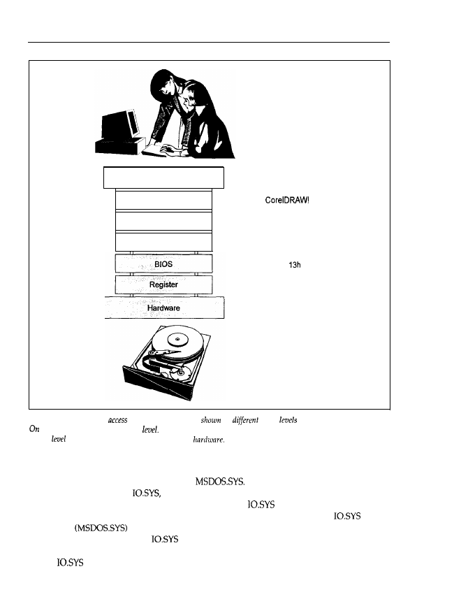
Main
Components
33
User
Application Program
High-level Language
D O S
Hans-Peter Messmer
Pascal
INT 21h
INT
Port If0
Hard Disk
Figure 1.26: Different
levels. On
the left are
the
access
between user and hardware.
the right is an example for each
The top level is the application, which is the interface to the user. The
bottom
is the registers that
directly control
the
are important for programmers and application programs, such as file opening, byte output via
the parallel interface, etc., are integrated in
These instructions are converted into
a command sequence for
therefore it is possible to adapt DOS to various hardware
environments simply by changing the hardware-oriented
part. Thus, the manufacturers
of PCs have the opportunity to choose different technical solutions. By adapting
accord-
ingly, DOS
is then able to access this different hardware in exactly the same way
as an original IBM PC because
converts all instructions into correct commands for the
different hardware. However, the passion of the Taiwanese for copying has made the adapta-
tion of
unnecessary, as at least 99.9999% of the hardware functions have been copied.
Therefore, no different registers or additional instructions are needed.
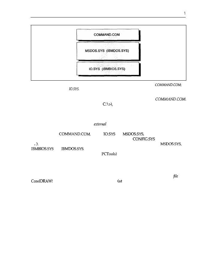
3 4
Chapter
Figure 1.27: The DOS components. DOS consists of three parts: the most user-oriented is
the most hardware-oriented
For a user, the command interpreter is of great importance. In DOS its name is
This program displays the prompt (typically
accepts your commands (DIR, COPY, etc.),
or loads and calls programs. Within the command interpreter the so-called
internal DOS commands
are incorporated. If you issue such a command (for example, DIR), COMMAND.COM executes
an internal routine (which, for example, executes a system call to read the directory of the floppy
or hard disk). On the other hand, the
DOS commands
are present as autonomous and
complete programs that are loaded and executed, as are all other application programs (Word,
for example), by
Unlike
and
COMMAND.COM may
be replaced by another command interpreter (by means of the
command SHELL
=
This again emphasizes that DOS is made up of the files IO.SYS and
or
and
They are located in the root directory as hidden files. With a
suitable utility (such as Norton Utilities or
which locates hidden files, you should be
able to track them down.
DOS, in turn, uses the BIOS to access certain hardware components. Usually, the BIOS supplies
programs for accessing drives, the graphics adapter and parallel/serial interfaces on a physical
(that is, hardware) level. Now you can see a distinct hierarchy: the menu item open
with
is converted by the high-level language
compile time) into system calls to DOS
(at runtime), where DOS in turn internally converts these calls and uses BIOS programs to
execute the menu item. In turn, the BIOS accesses the hardware by so-called registers. Registers
are certain interfaces that are directly assigned to hardware. Commands that directly control the
hardware operation are placed in registers. For example, the DMA chip, timer chip, graphics
controller chip and drive controllers are accessed via registers. By using appropriate values, data
exchange, the sound of a certain frequency, or various line frequencies on the monitor may be
set. The address, size and meaning of the registers are, of course, largely dependent on the
hardware. The job of the BIOS is to convert a defined function call into a corresponding com-
mand sequence for the registers concerned. Thus, the hierarchical concept of Figure 1.26 can be
understood: if you program an application by directly accessing registers, the resulting program
code can be executed only on a certain PC, and is therefore completely incompatible with other
machines because the manufacturer is, in principle, free to choose any address and meaning for
the registers. However, the access hierarchy, with its exactly defined interfaces between the
1
Main Components
35
different levels, allows (from the viewpoint of the application) a floppy drive with a 360 kbytes
capacity to be accessed in the same way as a modem hard disk with a capacity of several
gigabytes. BIOS and
execute the necessary adapations to the physical drive. That the
internal conversion of the menu item open file is very different for these two cases seems to
be natural.
It should be noted that with the aid of hardware-oriented high-level languages like C, for
example (and nowadays even with Pascal or BASIC), you have the opportunity to access the
BIOS and registers of a PC directly. Direct access to the BIOS in particular became established
with graphics applications or tools such as Norton Utilities or
Programmers want to
speed up the performance of their programs and use the graphics capabilities of a PC (DOS
doesn’t incorporate any system call to output a graphics point on-screen, for example). As can
be seen from Figure 1.26, you move around the operating system. In a PC with DOS this is not
critical, because you are always working alone and only one application is running at a time.
DOS is a singletasking
operating system.
More powerful computer systems
PCs with
UNIX or Windows NT also belong to this group), on the other hand, run with
a
multitasking operating system.
Popular resident programs such as the external DOS command
S
or Borland’s Sidekick occupy a position somewhere in the middle. PRINT prints files
s
independently of the actual application running but, in contrast to a background program in a
multitasking environment, the activation of PRINT is not carried out by the operating system
(DOS) but by the periodic timer interrupt. PRINT intercepts this interrupt to activate
itself
for
a certain self-defined time period. In contrast, with a multitasking operating system, all the
applications residing in memory are activated by the
operating system
for a time period defined
by the system. Thus, with OS/2 you can print a text while your CAD application is calculating
the reinforcement of a house in the background and you are editing a letter in the foreground.
Therefore, it is obvious that a multitasking system cannot allow any bypassing. In this case,
there may be events running in the computer that are not controlled by (and therefore hidden
from) the operating system. Actually,
memory
resident programs like PRINT and Sidekick for
DOS give the user some feeling of a multitasking environment.
1
A serious disadvantage of DOS is the so-called 640 kbytes boundary. This means that for all
programs (including the operating system) only 640 kbytes are available at most. The reason
is not some problem with space for memory chips or that memory is very expensive above
kbytes, but the memory organization defined by the designers of DOS (see Figure 1.28 for
a description of this organization).
Y
OU
can see that the first 640 kbytes (addresses
to 9999h) are reserved for programs.
In the lowest parts reside interrupt vectors, BIOS and DOS data areas, IO.SYS,
drivers and the resident part of COMMAND.COM. The
application programs area
(reserved for
programs like Word or
runs on from this. At the upper end the transient part
of COMMAND.COM overlaps with the application program area. To use memory as efficiently
as possible, COMMAND.COM is divided into two parts: the resident part holds the routines
that are, for example, necessary to load the transient part after completion or abortion of an
application; the transient part holds the internal commands like DIR and COPY that are not
necessary during execution of the application program, and which thus may be overwritten.
Resident means that the corresponding code remains in
memory even
when the application is
loaded: the code will not be overwritten under any circumstances; transient means that the
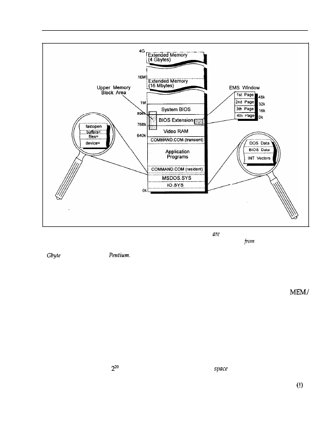
3 6
Chapter
1
Figure 1.28: DOS memory organization. With DOS the first 640 kbytes reserved for the operating system and
application programs. Above the first 640 kbytes there is the video RAM, and starting
768 kbytes there
follow
various (and optional)
BIOS
extensions.
Above 1 Mbyte extended memory starts, which can be up to
4
on an i386, i486 or
corresponding program code can be overwritten to enhance the memory space for the applica-
tion’s code and data. Starting with DOS 4.0, you may determine the occupation of the first 640
kbytes by system and application programs, drivers, buffers, etc. using the command
PROGRAM or MEM/DEBLJG.
Above the 640 kbyte boundary are the 128 kbytes of the video RAM (see also Figure 1.9). The
next 128 kbytes are reserved for BIOS extensions on graphics adapters and controllers (see also
Figures 1.9 and 1.12). Above this there are 128 kbytes for the system BIOS on the motherboard
(see Figure 1.7). In the original IBM PC, the ROM BASIC is also integrated into this area. All
memory areas in total give a memory of 1 Mbyte.
The first two processors (8088 and 8086) had 20 lines for the address bus, and they could
address a maximum of = 1 Mbyte. Therefore, an address
(the number of addressable
bytes) of 1 Mbyte was assumed and divided in the way described above. This separation was
completely arbitrary, but you should notice that the first PC was delivered with 64 kbytes
of
main memory. The reservation of the lower 640 kbytes for application programs and DOS (with
16 kbytes at that time) seemed as if it would be enough to last for decades. The designers of DOS
were caught completely unawares by later developments in computing, and therefore we are
now struggling with this 640 kbyte boundary in the era of cheap and high-capacity memory chips.
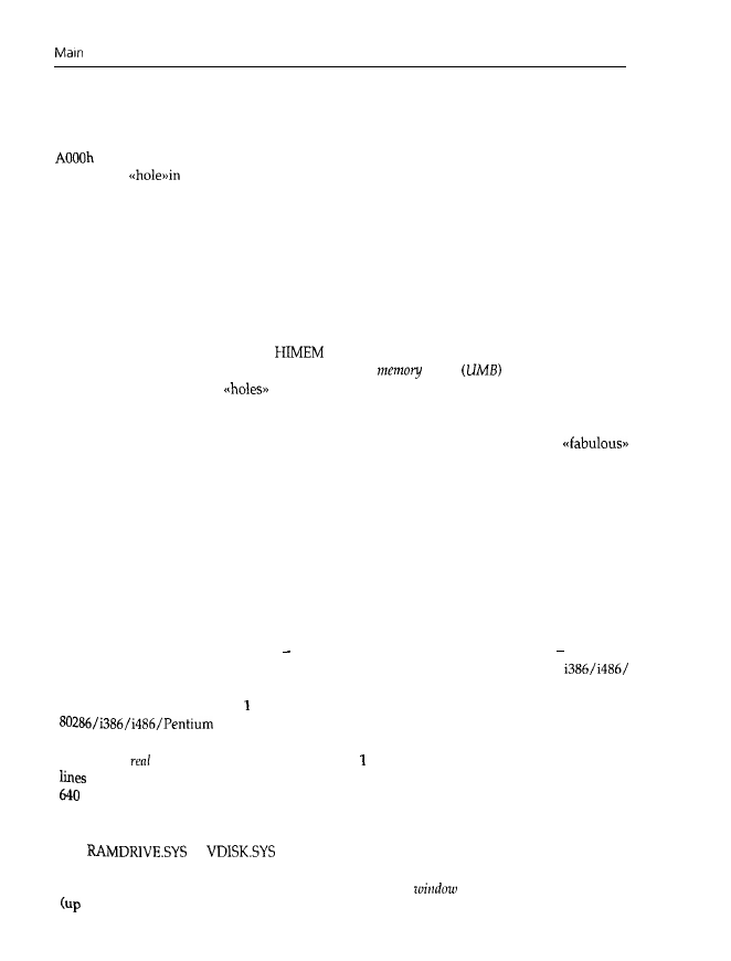
Components
37
In
particular, it is worth noting that the individual areas of the memory organization need not
be completely filled. For example, it is possible to limit the main memory (the reserved lower
640 kbytes) to 256 kbytes instead of using the full 640 kbytes. That doesn’t change the address
of the video memory in any way. The 384 kbytes in between remain empty and virtually
constitute a
the address space. In the same way, the amount of the reserved areas for
video RAM and ROM BIOS actually used has no influence on their location in the address
space.
Unfortunately, because of the concept of the PC (and DOS), it is impossible to fill these holes
with additional RAM. The CPU may not be able to access the corresponding memory chips,
therefore all DOS programs are limited to a size of 640 kbytes less the memory area occupied
by the system. Meanwhile DOS, together with all its drivers (for printer, screen, mouse, etc.)
occupies a large amount of memory, so that less and less memory remains for application
programs. Version 5.0 together with at least an 80286 chip offers progress to some extent. Here
a large part of DOS is moved to the
area or extended/expanded memory. The ultimate
quantity of memory is formed by the so-called
upper
blocks
between 640 kbytes
and 1 Mbyte. They occupy
in the address space above 640 kbytes between the various
ROMs (system, VGA, SCSI, etc.). The user must explicitly supply the ranges of already occupied
address regions. In this way, for, example, the keyboard driver can be located between the VGA
BIOS and a SCSI ROM. Application programs then have the opportunity to use a
620 kbytes of memory.
In the application area, the called program is stored and may itself request memory for its own
purposes, for example to load a text file into memory. As the extent of the text file can’t be fore-
seen at programming time, memory is assigned dynamically. This means that the application
has to inform DOS how much memory is needed for the text file, and DOS assigns it to the
application. That is the reason why some programs display the message Not
enough memory!,
although enough memory was available for loading the program. A request to DOS to provide
additional
memory
for the text file can’t be fulfilled by the operating system if there is too little
memory available.
An important advance with the AT or better, the 80286 processor and higher is that the
80286, with its 24 address lines, can now address 16 Mbytes of memory (and the
Pentium with 32 address lines can address 4 Gbytes). But this only works
in the so-called
protected
mode.
Memory above Mbyte is called extended memory, and may be accessed by an
processor in protected mode only. This advanced protected mode is
wholly incompatible with DOS. To retain compatibility, even the i386, i486 and Pentium are
operated in
mode. Here they can only address Mbyte of memory, even though 32 address
are present. Therefore, PCs with i386, i486 or Pentium processors are also subject to the
kbyte boundary for application programs. However, Windows and OS/2 successfully
attempt to break through this barricade. Switching between real and protected mode is possible
to allow access to extended memory for at least a certain time. This method is used by programs
like
or
for virtual drives. Another possibility is that a 64 kbyte
region of memory may be inserted into free memory above the 640 kbyte boundary (into a hole
in the address space); this region constitutes a so-called
into a much larger
memory
to
8 Mbytes). This large memory is called
expanded memory,
or EMS
memory.
By
means of

3 8
Chapter
appropriate commands to registers on an EMS memory expansion adapter, the window (which
consists of four partial windows) may be moved within the EMS memory. Therefore, the
8 Mbytes are available in sections of 64 kbytes (or 4 16 kbytes) each. Details about real and
protected mode, as well as extended and expanded
memory,
are given later.
Wyszukiwarka
Podobne podstrony:
JUMA RX1 main components
computer hardware configuration worksheet doc
Symmetrical components method continued
24 G23 H19 QUALITY ASSURANCE OF BLOOD COMPONENTS popr
Pirates of the Spanish Main Smuggler's Song
C20090551288 B9780323067942000420 main
C20090551288 B9780323067942000055 main
P000476 D Eng Main dimensions
components microwave
Computerspieler Jargon
268257 Introduction to Computer Systems Worksheet 1 Answer sheet Unit 2
cloud computing1
Main (3)
ALAN42 MULTI component side
COMPUTER
C20090551288 B9780323067942000407 main
FX3U Hardware A4 pol
Component Based Automation
juma rx1 main SCH Rev E
więcej podobnych podstron