Installation Manual
Version 6.6
April 2012
Document #: LTRT-59815
MediaPack
TM
Series
MP-11x & MP-124
Analog VoIP Gateways


Version 6.6
3
April 2012
Hardware Installation Manual
Contents
Table of Contents
1
Introduction ......................................................................................................... 7
2
MP-11x Hardware Installation ............................................................................ 9
2.1
Physical Description ................................................................................................. 9
2.1.1
MP-11x Front Panel (LEDs Description) ................................................................... 9
2.1.2
MP-11x Rear Panel (Ports Description) .................................................................. 10
2.2
Unpacking and Checking Package Contents ......................................................... 10
2.3
Mounting MP-11x ................................................................................................... 11
2.3.1
Desktop Mounting ................................................................................................... 12
2.3.2
Wall Mounting ......................................................................................................... 12
2.3.3
19-inch Rack Mounting ........................................................................................... 12
2.4
Cabling MP-11x ...................................................................................................... 14
2.4.1
Connecting MP-11x to the Ethernet Network ......................................................... 14
2.4.2
Connecting MP-11x to FXS Interfaces.................................................................... 15
2.4.3
Connecting MP-11x to FXO Interfaces ................................................................... 16
2.4.4
Connecting MP-11x to Analog FXS Lifeline Phone ................................................ 17
2.4.5
Connecting MP-11x to Computer for Serial Communication .................................. 18
2.4.6
Connecting MP-11x to Power ................................................................................. 20
3
MP-124 Hardware Installation .......................................................................... 21
3.1
Physical Description ............................................................................................... 21
3.1.1
MP-124 Front Panel ................................................................................................ 21
3.1.1.1
Reset Pinhole Button ............................................................................... 21
3.1.1.2
LEDs Description ..................................................................................... 21
3.1.2
MP-124 Rear Panel ................................................................................................ 22
3.2
Unpacking and Checking Package Contents ......................................................... 23
3.3
Mounting MP-124 ................................................................................................... 24
3.3.1
Desktop Mounting ................................................................................................... 24
3.3.2
19-inch Rack Mounting ........................................................................................... 24
3.4
Cabling MP-124 ...................................................................................................... 26
3.4.1
Power Surge Protection and Grounding ................................................................. 27
3.4.2
Connecting MP-124 to the Ethernet Network ......................................................... 29
3.4.3
Connecting MP-124 to FXS Interfaces ................................................................... 30
3.4.4
Connecting MP-124 to a Computer for Serial Communication ............................... 32
3.4.5
Connecting MP-124 to Power ................................................................................. 33
3.4.5.1
AC Power Supply..................................................................................... 33
3.4.5.2
DC Power Supply .................................................................................... 34

Hardware Installation Manual
4
Document #: LTRT-59815
MediaPack Series
List of Figures
Figure 2-1: MP-11x Front Panel (e.g., MP-118) ...................................................................................... 9
Figure 2-2: MP-11x Rear Panel (e.g., MP-118) ..................................................................................... 10
Figure 2-3: MP-11x Underside ............................................................................................................... 11
Figure 2-4: 19-inch Rack Shelf for MP-11x ........................................................................................... 12
Figure 2-5: MP-11x Rack Mount Installation ......................................................................................... 13
Figure 2-6: RJ-45 Connector Pinouts for Ethernet Connection ............................................................. 14
Figure 2-7: Connecting to the Ethernet ................................................................................................. 14
Figure 2-8: RJ-11 Connector Pinouts for FXS Interface ........................................................................ 15
Figure 2-9: Connecting FXS Interfaces ................................................................................................. 15
Figure 2-10: RJ-11 Connector Pinouts for FXO Interface ..................................................................... 16
Figure 2-11: Connecting FXO Interfaces ............................................................................................... 16
Figure 2-12: RJ-11 Lifeline Splitter Connector Pinouts ......................................................................... 17
Figure 2-13: Lifeline Cabling (Using Splitter Cable) for FXS-Only Devices ........................................... 17
Figure 2-14: Lifeline Cabling for FXS and FXO Devices ....................................................................... 18
Figure 2-15: PS/2 to DB-9 Adaptor Connector Pinouts ......................................................................... 18
Figure 2-16: PS/2 Connector Pinouts .................................................................................................... 18
Figure 2-17: Connecting the Serial Port ................................................................................................ 19
Figure 2-18: Connecting to the Power Supply ....................................................................................... 20
Figure 3-1: MP-124 Front Panel ............................................................................................................ 21
Figure 3-2: Rear Panel of MP-124 AC Powered Model ......................................................................... 22
Figure 3-3: Rear Panel of MP-124 DC Powered Model ........................................................................ 22
Figure 3-4: MP-124 Desktop Mounting .................................................................................................. 24
Figure 3-5: MP-124 with Brackets for Rack Installation ......................................................................... 24
Figure 3-6: Grounding and Power Surge Protection ............................................................................. 28
Figure 3-7: RJ-45 Connector Pinouts for Ethernet Connection ............................................................. 29
Figure 3-8: Connecting to the Ethernet ................................................................................................. 29
Figure 3-9: 50-pin Telco Connector ....................................................................................................... 30
Figure 3-10: MP-124 in a 19-inch Rack with MDF Adaptor ................................................................... 31
Figure 3-11: MP-124 RS-232 Connector Pinouts .................................................................................. 32
Figure 3-12: MP-124 Serial Cabling ...................................................................................................... 32
Figure 3-13: AC Power Cabling ............................................................................................................. 33
Figure 3-14: Wired DC Power Terminal Block Connected to MP-124 .................................................. 34
List of Tables

Version 6.6
5
April 2012
Hardware Installation Manual
Notices
Notice
This Installation Manual describes the hardware installation and quick configuration setup for
AudioCodes MediaPack series Voice-over-IP (VoIP) SIP media gateways.
Information contained in this document is believed to be accurate and reliable at the time of
printing. However, due to ongoing product improvements and revisions, AudioCodes cannot
guarantee accuracy of printed material after the Date Published nor can it accept responsibility
for errors or omissions.
Before consulting this document, check the corresponding Release Notes regarding feature
preconditions and/or specific support in this release. In cases where there are discrepancies
between this document and the Release Notes, the information in the Release Notes
supersedes that in this document. Updates to this document and other documents as well as
software files can be downloaded by registered customers at
http://www.audiocodes.com/downloads
© Copyright 2012 AudioCodes Ltd. All rights reserved.
This document is subject to change without notice.
Date Published: April-18-2012
Trademarks
AudioCodes, AC, AudioCoded, Ardito, CTI2, CTI², CTI Squared, HD VoIP, HD VoIP
Sounds Better, InTouch, IPmedia, Mediant, MediaPack, NetCoder, Netrake, Nuera, Open
Solutions Network, OSN, Stretto, TrunkPack, VMAS, VoicePacketizer, VoIPerfect,
VoIPerfectHD, What’s Inside Matters, Your Gateway To VoIP and 3GX are trademarks or
registered trademarks of AudioCodes Limited. All other products or trademarks are property
of their respective owners.
WEEE EU Directive
Pursuant to the WEEE EU Directive, electronic and electrical waste must not be disposed
of with unsorted waste. Please contact your local recycling authority for disposal of this
product.
Customer Support
Customer technical support and service are generally provided by AudioCodes’
Distributors, Partners, and Resellers from whom the product was purchased. For technical
support for products purchased directly from AudioCodes, or for customers subscribed to
AudioCodes Customer Technical Support (ACTS), contact
Abbreviations and Terminology
Each abbreviation, unless widely used, is spelled out in full when first used.
Hardware Installation Manual
6
Document #: LTRT-59815
MediaPack Series
Regulatory Information
The Regulatory Information can be viewed at
http://www.audiocodes.com/downloads
Related Documentation
Document Name
SIP Product Reference Manual
SIP Release Notes
MP-11x & MP-124 SIP User's Manual
MP-124 AC SIP Fast Track Guide
MP-124 DC SIP Fast Track Guide
MP-11x SIP Fast Track Guide
CPE Configuration Guide for IP Voice Mail
Notes:
Throughout this manual and unless otherwise specified, the following terms
are used:
•
Device refers to the MediaPack series gateways.
•
MediaPack refers to MP-112, MP-114, MP-118, and MP-124.
•
MP-11x refers to MP-112, MP-114, and MP-118.
Note:
The MP-11x and MP-124 devices are indoor units and therefore, must be
installed only indoors. However, the MP-124 FXS telephony cables can be
routed outdoors (MP-124 part numbers MP-124/24S/AC/OD and MP-
124/24S/DC/OD). See Section
for surge protection means required
when such outdoor cabling is implemented.
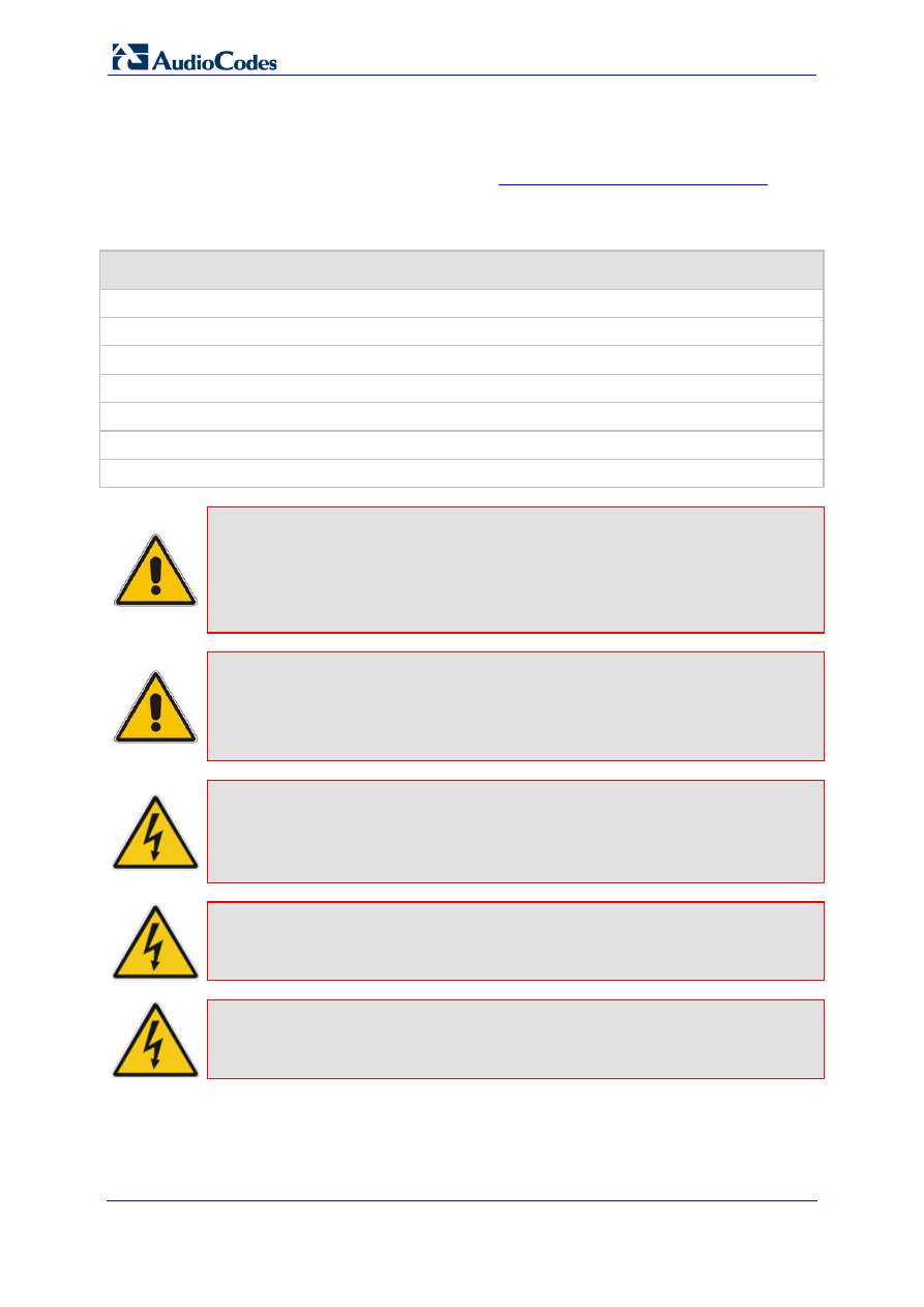
Caution Electrical Shock
Do not open or disassemble this device. The device carries high voltage and
contact with internal components may expose you to electrical shock and
bodily harm.
Warning:
The device is supplied as a sealed unit and must only be serviced by
qualified service personnel.
Warning:
Disconnect the device from the mains and Telephone Network Voltage
(TNV) before servicing.

Version 6.6
7
April 2012
Hardware Installation Manual
1. Introduction
1
Introduction
This document describes the hardware installation of the MediaPack MP-1xx product
series. The MP-1xx series includes the following models:
MP-11x:
•
MP-112
•
MP-114
•
MP-118
MP-124
The table below compares the telephony support between these MP1xx models:
Table 1-1: MP-1xx Model Telephony Support
MP-1xx Model
FXS
FXO
Combined
FXS + FXO
Number of
Channels
MP-112
2
MP-114
2 + 2
4
MP-118
4 + 4
8
MP-124
24

Hardware Installation Manual
8
Document #: LTRT-59815
MediaPack Series
Reader’s Notes
Version 6.6
9
April 2012
Hardware Installation Manual
2. MP-11x Hardware Installation
2
MP-11x Hardware Installation
This chapter describes the MP-11x hardware installation.
2.1
Physical Description
The subsections below provide a physical description of the front and rear panels of the
MP-11x.
2.1.1
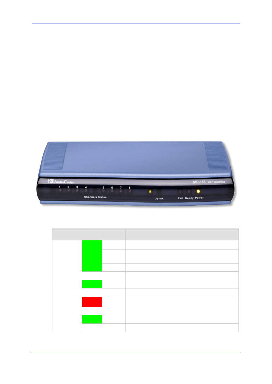
MP-11x Front Panel (LEDs Description)
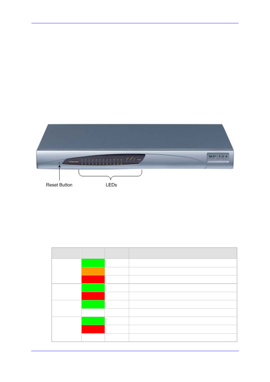
The device's front panel provides LEDs for indicating various operating statuses. The figure
below displays the front panel of the MP-118. This is similar to the MP-114 and MP-112
models, differing only in the number of Channel Status LEDs (corresponding to the
number of channels).
Figure 2-1: MP-11x Front Panel (e.g., MP-118)
The device’s LEDs are described in the table below:
Table 2-1: MP-11x Front-Panel LEDs Description
LED
Color
State
Definition
Channels
Status
Green
Blinking
Phone is ringing (incoming call, before answering).
Fast
Blinking
Line malfunction.
On
Phone is in off-hook position or ringing.
-
Off
Phone is in on-hook position.
Uplink
Green
On
Valid 10/100Base-TX Ethernet connection.
-
Off
No Ethernet uplink.
Fail
Red
On
Failure (fatal error) or system initialization.
-
Off
Normal working condition.
Ready
Green
On
Device powered up, self-test OK.
-
Off
Loading software or system failure.
Hardware Installation Manual
10
Document #: LTRT-59815
MediaPack Series
LED
Color
State
Definition
Power
Green
On
Power is received by the device.
-
Off
Failure / disruption in the AC power supply or power
is currently not being supplied to the device through
the AC power supply entry.
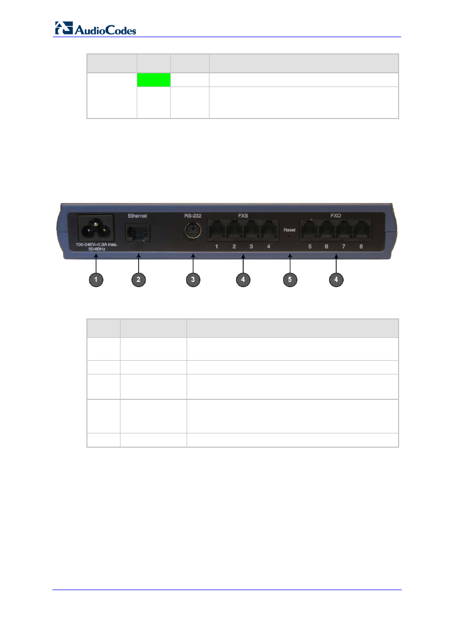
2.1.2
MP-11x Rear Panel (Ports Description)
The device's rear panel provides the ports for cabling the device to the various interfaces.
The figure below displays the rear panel of the MP-118 device (as an example).
Figure 2-2: MP-11x Rear Panel (e.g., MP-118)
The table below describes the ports on the MP-11x rear panel:
Table 2-2: MP-11x Rear Panel Component Descriptions
Item #
Label
Component Description
1
100-240~0.3A
max. 50-60Hz
AC power supply socket.
2
Ethernet
10/100Base-TX Uplink port.
3
RS-232
RS-232 status port (requires a DB-9 to PS/2 adaptor).
Note: MP-112 does not provide a serial port.
4
FXS and/or FXO
Provides two, four, or eight FXS/FXO ports (depending on
MediaPack model).
Note: MP-112 does not support FXO interfaces.
5
Reset
Reset button for resetting the device.
2.2
Unpacking and Checking Package Contents
Follow the procedure below for unpacking the carton in which MP-11x is shipped.
To unpack MP-11x:
1.
Open the carton and remove the packing materials.
2.
Remove the MP-11x unit from the carton.
3.
Check that there is no equipment damage.
Version 6.6
11
April 2012
Hardware Installation Manual
2. MP-11x Hardware Installation
4.
Ensure that in addition to the MP-11x unit, the package contains the following items:
•
AC power cable.
•
Small plastic bag containing four anti-slide bumpers for desktop installation.
•
Regulatory Information document.
5.
Check, retain, and process any documents.
6.
Notify AudioCodes or your local supplier of any damage or discrepancies.
2.3
Mounting MP-11x
The device can be mounted in one of the following ways:
Desktop mounting - see 'Desktop Mounting' on page
Wall mounting - see 'Wall Mounting' on page
Standard 19-inch rack mounting - see '19-inch Rack Mounting' on page
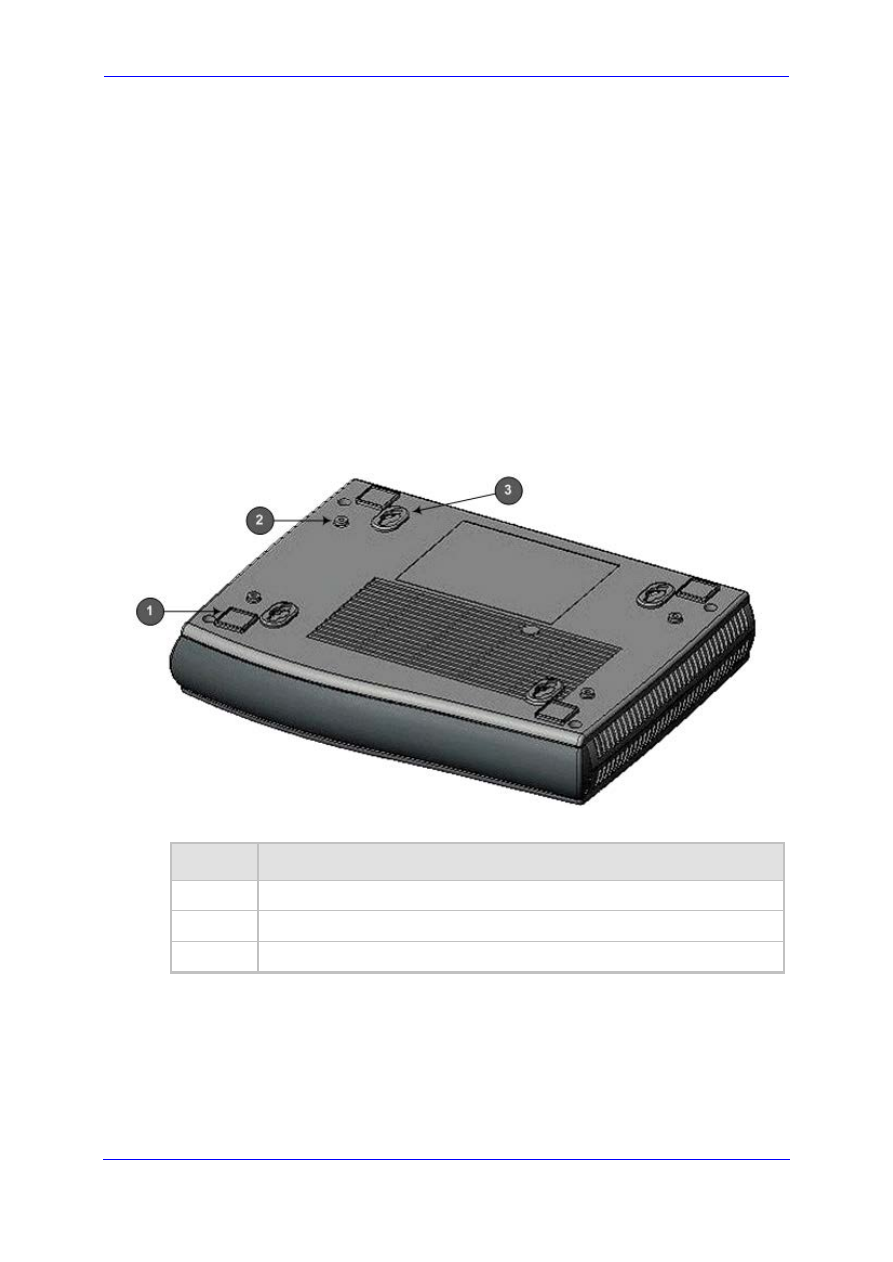
The figure below shows the mounting components on the underside of MP-11x:
Figure 2-3: MP-11x Underside
Table 2-3: Mounting Components on MP-11x Underside
Item #
Description
1
Square slot used to attach anti-slide bumpers (for desktop mounting).
2
Screw opening used to attach MP-11x to a 19-inch shelf rack.
3
Oval notch used to attach MP-11x to a wall.
Hardware Installation Manual
12
Document #: LTRT-59815
MediaPack Series
2.3.1
Desktop Mounting
Attach the four (supplied) anti-slide bumpers to the base of MP-11x and place it on a
desktop in the desired position.
2.3.2
Wall Mounting
Follow the procedure below for mounting MP-11x on a wall.
To mount MP-11x on a wall:
1.
Drill four holes according to the following dimensions:
•
Horizontal distance between holes: 140 mm (5.51 inches)
•
Vertical distance between: 101.4 mm (4 inches)
2.
Insert a wall anchor of the appropriate size into each hole.
3.
Fasten a DIN 96 3.5 x 20 wood screws (not supplied) into each of the wall anchors.
4.
Position the four oval notches, located on the underside of MP-11x (see Item #3 in
'Mounting MP-11x' on page
), over the four screws and hang MP-11x on them.
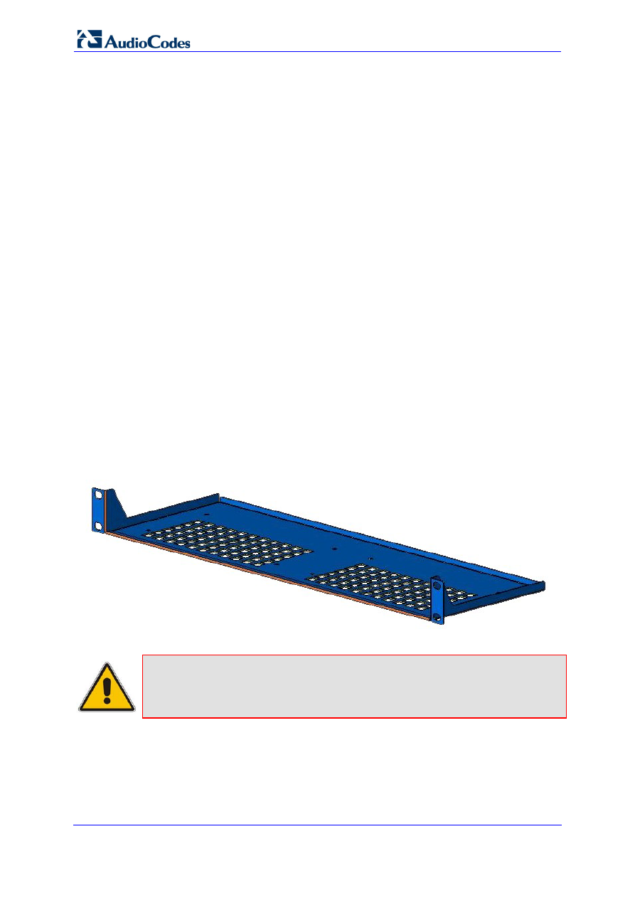
2.3.3
19-inch Rack Mounting
MP-11x can be installed in a standard 19-inch rack by placing it on an AudioCodes' 19-inch
rack-mounting shelf (special customer order) that must be pre-installed in a rack. The shelf
can hold up to two MP-11x devices. The rack-mounting shelf can be ordered separately
from AudioCodes. The 19-inch rack installation package contains a single shelf (shown in
the figure below), and eight shelf-to-device screws.
Figure 2-4: 19-inch Rack Shelf for MP-11x
Note:
The 19-inch rack shelf is not supplied in the standard package kit, but can be
ordered separately: Bulk Pack package (MCMK00015) containing 10 rack
mounting shelves for MP-11x. For ordering and pricing, please contact your
AudioCodes' sales representative.
Version 6.6
13
April 2012
Hardware Installation Manual
2. MP-11x Hardware Installation
To install MP-11x in a 19-inch rack:
1.
Attach one or two MP-11x devices to the shelf using the shelf-to-device screws
(supplied).
2.
Position the shelf in the rack and align its side holes with the rack frame holes.
3.
Attach the shelf to the rack using four standard rack screws (not supplied).
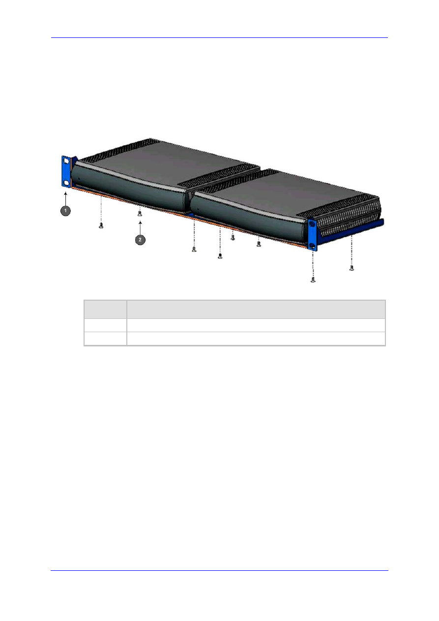
Figure 2-5: MP-11x Rack Mount Installation
Table 2-4: MP-11x Rack Mount
Item #
Functionality
1
Standard rack holes used to attach the shelf to the rack.
2
Eight shelf-to-device screws.
Hardware Installation Manual
14
Document #: LTRT-59815
MediaPack Series
2.4
Cabling MP-11x
This section describes the MP-11x cabling procedures:
To cable MP-11x:
Connecting to the Ethernet network – see 'Connecting MP-11x to the Network' on
page
Connecting to FXS/FXO devices – see 'Connecting MP-11x to FXS/FXO Devices' on
page
Cabling the FXS Lifeline – see 'Cabling MP-11x FXS Lifeline' on page
Serial connection to a computer – see 'Connecting MP-11x RS-232 Port to a PC' on
page
Connecting to the power supply – see 'Connecting MP-11x to Power' on page
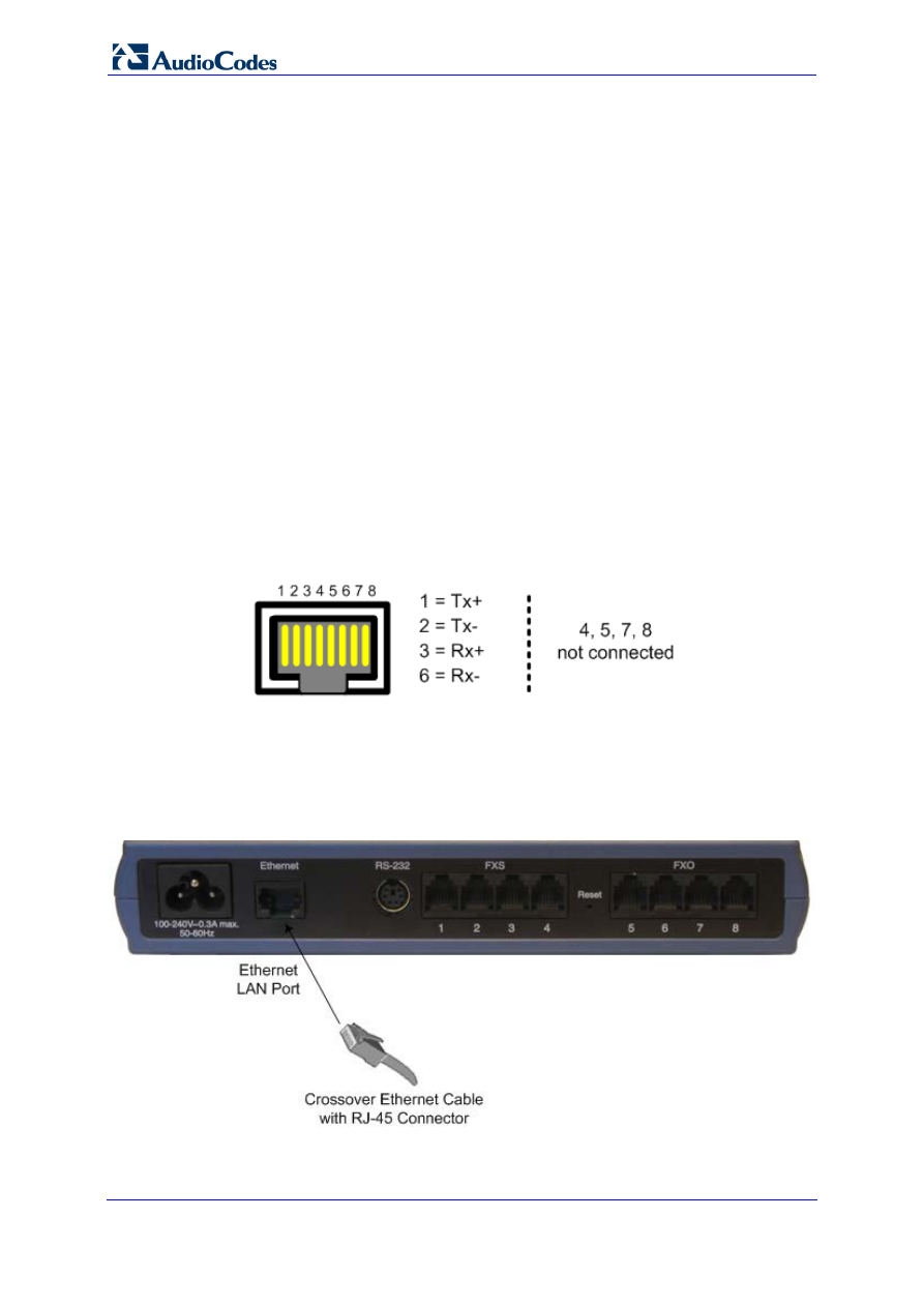
2.4.1
Connecting MP-11x to the Ethernet Network
The procedure below describes how to connect MP-11x directly to the Ethernet network.
This cabling requires a crossover Ethernet cable with the following RJ-45 connector
pinouts:
Figure 2-6: RJ-45 Connector Pinouts for Ethernet Connection
To connect MP-11x directly to the Ethernet network:
1.
Connect one end of a crossover RJ-45 Ethernet cable to the Ethernet port (labeled
Ethernet).
Figure 2-7: Connecting to the Ethernet
2.
Connect the other end of the cable to the network.
Version 6.6
15
April 2012
Hardware Installation Manual
2. MP-11x Hardware Installation
2.4.2
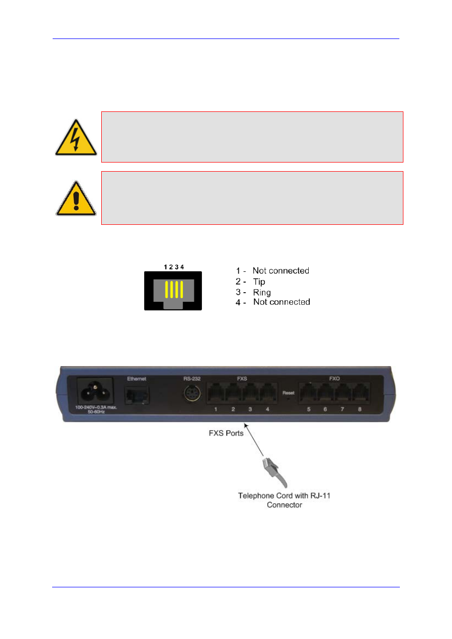
Connecting MP-11x to FXS Interfaces
The procedure below describes how to cable the MP-11x FXS interfaces.
Warnings:
•
Ensure that you connect FXS ports only to analog telephones; otherwise,
damage to MP-11x may occur.
•
FXS ports are considered TNV-3
Note:
FXS (Foreign Exchange Station) is the interface replacing the Exchange (i.e.,
the CO or the PBX) and connects to analog telephones, dial-up modems, and
fax machines. The FXS is designed to supply line voltage and ringing current
to these telephone devices. An FXS VoIP device interfaces between the
analog telephone devices and the Internet.
This cabling requires a two-wire telephone cord with the following RJ-11 connector pinouts:
Figure 2-8: RJ-11 Connector Pinouts for FXS Interface
To connect MP-11x to FXS interfaces:
1.
Connect one end of an RJ-11 two-wire telephone cord to the desired FXS port (labeled
FXS).
Figure 2-9: Connecting FXS Interfaces
2.
Connect the other end of the cord to the required telephone interface (e.g., fax
machine, dial-up modem, or analog POTS telephone).
Hardware Installation Manual
16
Document #: LTRT-59815
MediaPack Series
2.4.3
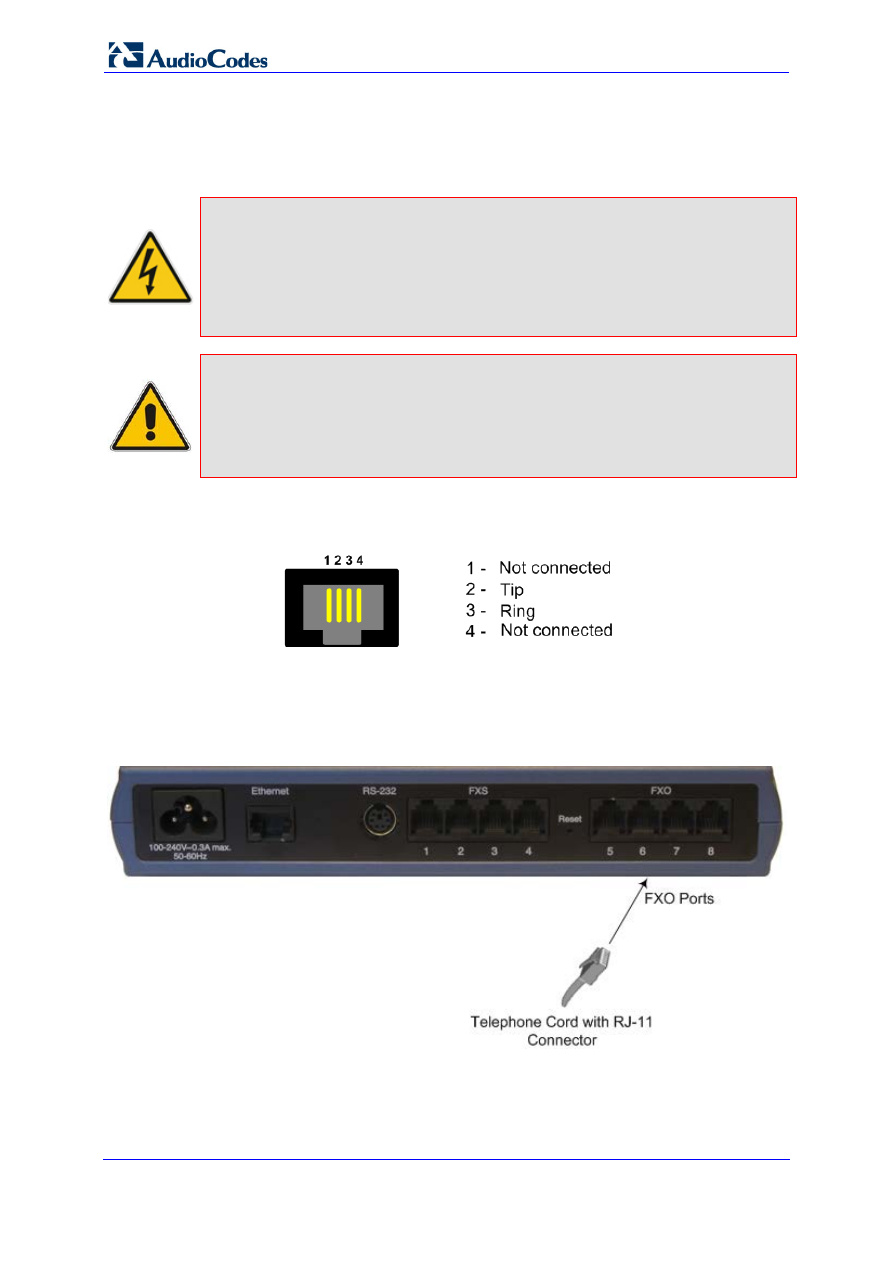
Connecting MP-11x to FXO Interfaces
The procedure below describes how to cable the MP-11x FXO interfaces.
Warnings:
•
Ensure that you connect FXO ports only to CO/PBX lines; otherwise,
damage to MP-11x may occur.
•
To protect against electrical shock and fire, use a 26 AWG minimum wire
to connect FXO ports to the PSTN.
•
FXO ports are considered TNV-3
Note:
FXO (Foreign Exchange Office) is the interface replacing the analog
telephone and connects to a Public Switched Telephone Network (PSTN) line
from the Central Office (CO) or to a Private Branch Exchange (PBX). The
FXO is designed to receive line voltage and ringing current, supplied from the
CO or the PBX (just like an analog telephone). An FXO VoIP device
interfaces between the CO/PBX line and the Internet.
This cabling requires a two-wire telephone cord with the following RJ-11 connector pinouts:
Figure 2-10: RJ-11 Connector Pinouts for FXO Interface
To connect MP-11x to FXO devices:
1.
Connect one end of an RJ-11 cable to the desired FXO port (labeled FXO).
Figure 2-11: Connecting FXO Interfaces
2.
Connect the other end of the cable to the required telephone interface (e.g., telephone
exchange analog lines or PBX extensions).
Version 6.6
17
April 2012
Hardware Installation Manual
2. MP-11x Hardware Installation
2.4.4
Connecting MP-11x to Analog FXS Lifeline Phone
The Lifeline provides a wired analog POTS phone connection to any PSTN or PBX FXS
port when there is no power or when the network connection fails. Therefore, you can use
the Lifeline phone even when MP-11x is not powered or not connected to the network.
The Lifeline feature is implemented as follows, depending on FXO/FXS support:
For devices providing only FXS ports: A single Lifeline connected to Port #1 using a
splitter (not supplied) is available.
For devices providing FXS and FXO ports: A splitter is not required - all FXS ports
are automatically connected to corresponding FXO ports (i.e., FXS Port #1 to FXO
Port #5, FXS Port #2 to FXO Port #6, and so on).
For devices providing only FXO ports: A Lifeline is not available.
Notes:
•
The Lifeline feature is not supported by MP-112.
•
The use of the Lifeline upon network failure can be disabled using the
LifeLineType ini file parameter (described in the User's Manual).
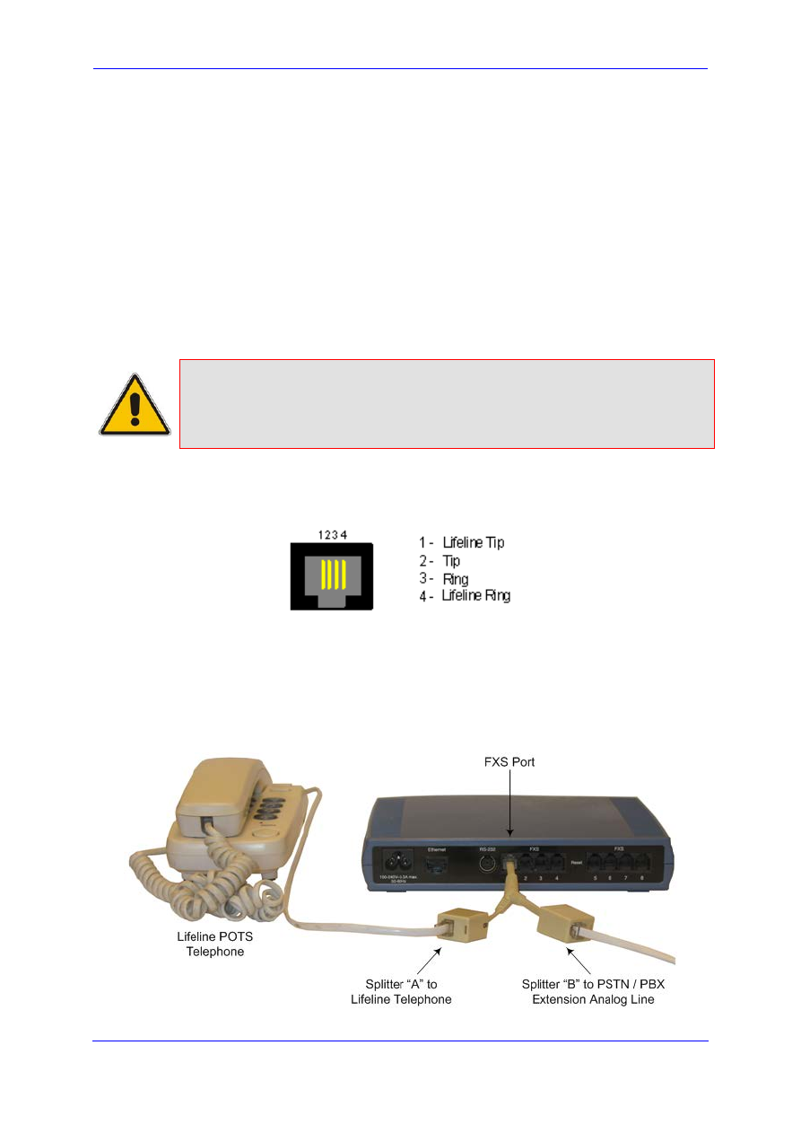
The Lifeline’s splitter connects pins #1 and #4 to another source of an FXS port, and pins
#2 and #3 to the POTS (FXS) phone. See the Lifeline splitter pinouts in the figure below:
Figure 2-12: RJ-11 Lifeline Splitter Connector Pinouts
To cable the MP-11x FXS Lifeline:
1.
Connect the Lifeline splitter to Port #1 on MP-11x (the Lifeline splitter is a special order
option).
2.
Connect the Lifeline phone to Port A on the Lifeline splitter.
3.
Connect an analog PSTN line to Port B on the Lifeline splitter.
Figure 2-13: Lifeline Cabling (Using Splitter Cable) for FXS-Only Devices
Hardware Installation Manual
18
Document #: LTRT-59815
MediaPack Series
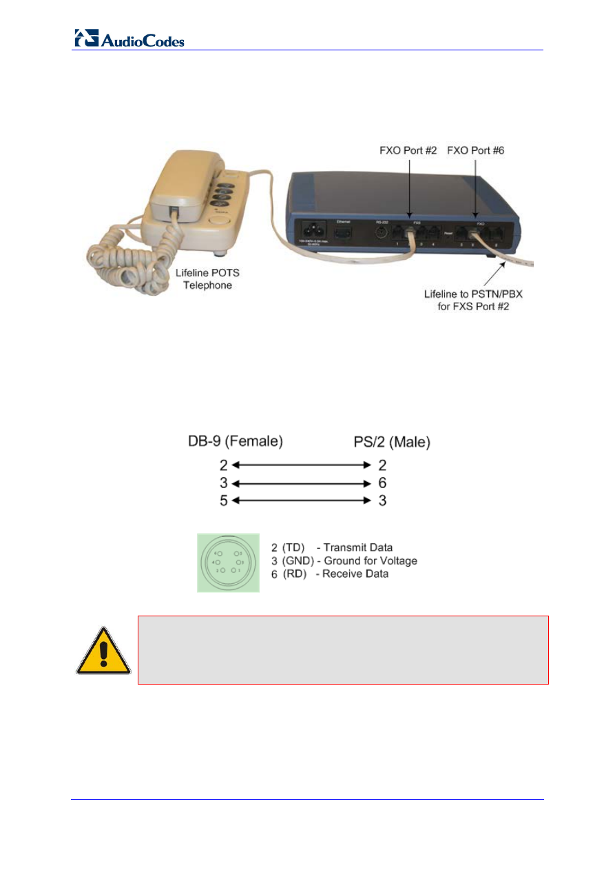
To cable the combined MP-11x FXS/FXO Lifeline:
1.
Connect a fax machine, modem, or phone to each of the FXS ports.
2.
Connect an analog PSTN line to each of the FXO ports.
Figure 2-14: Lifeline Cabling for FXS and FXO Devices
2.4.5
Connecting MP-11x to Computer for Serial Communication
The procedure below describes how to connect the MP-11x serial (RS-232) interface to a
computer.
This cabling requires a straight-through PS/2 to DB-9 cable adaptor with the following
connector pinouts:
Figure 2-15: PS/2 to DB-9 Adaptor Connector Pinouts
Figure 2-16: PS/2 Connector Pinouts
Notes:
•
This procedure is not applicable to MP-112 as this model does not
provide an RS-232 serial interface port.
•
The PS/2 to DB-9 cable adaptor is not included in the MP-11x package.
Version 6.6
19
April 2012
Hardware Installation Manual
2. MP-11x Hardware Installation
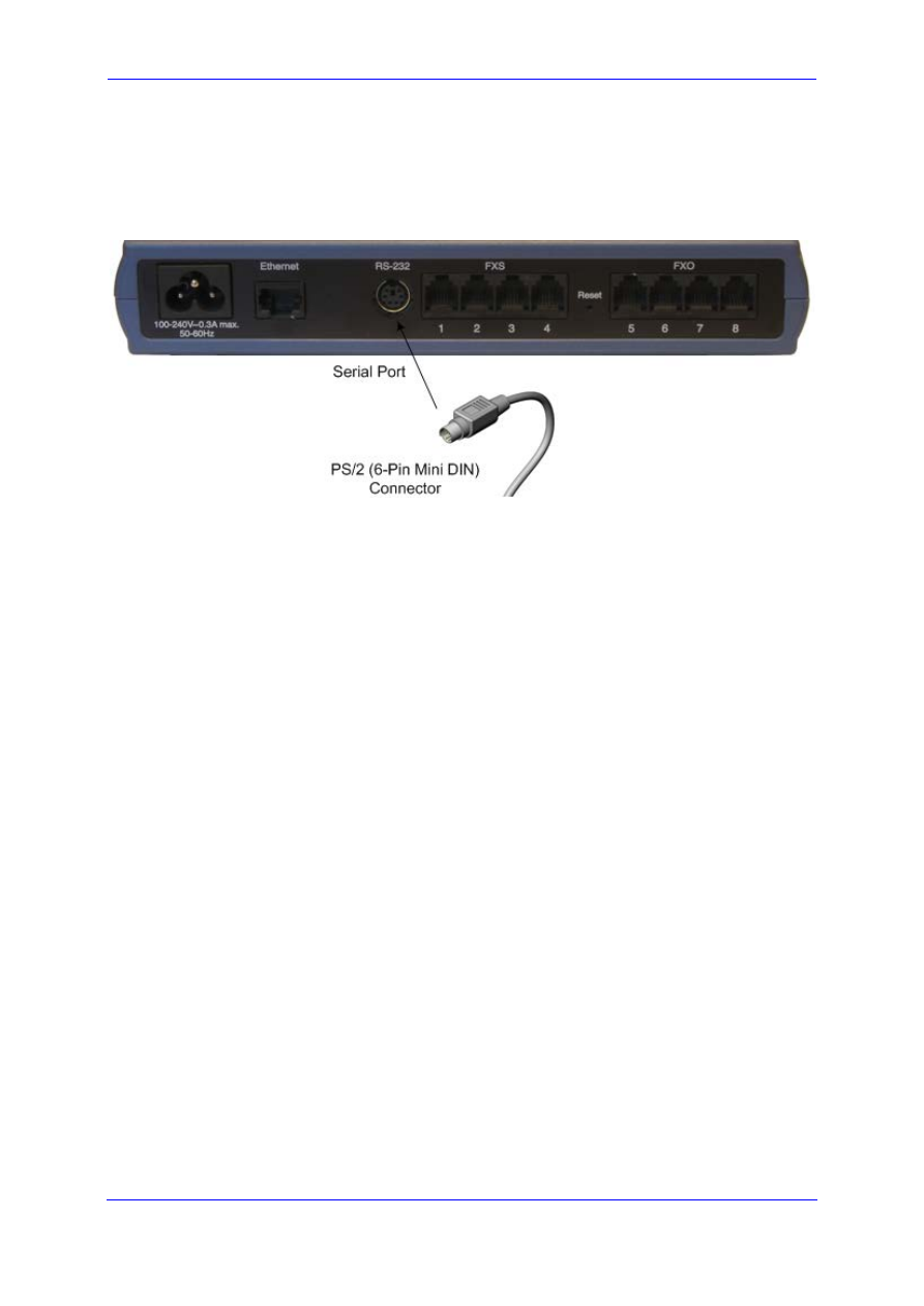
To connect MP-11x to a computer for serial communication:
1.
Connect the PS/2 connector on one end of the cable to the MP-11x RS-232 port
(labeled RS-232).
Figure 2-17: Connecting the Serial Port
2.
Connect the DB-9 connector at the other end of the cable to either the COM1 or COM2
RS-232 communication port on your computer.
Hardware Installation Manual
20
Document #: LTRT-59815
MediaPack Series
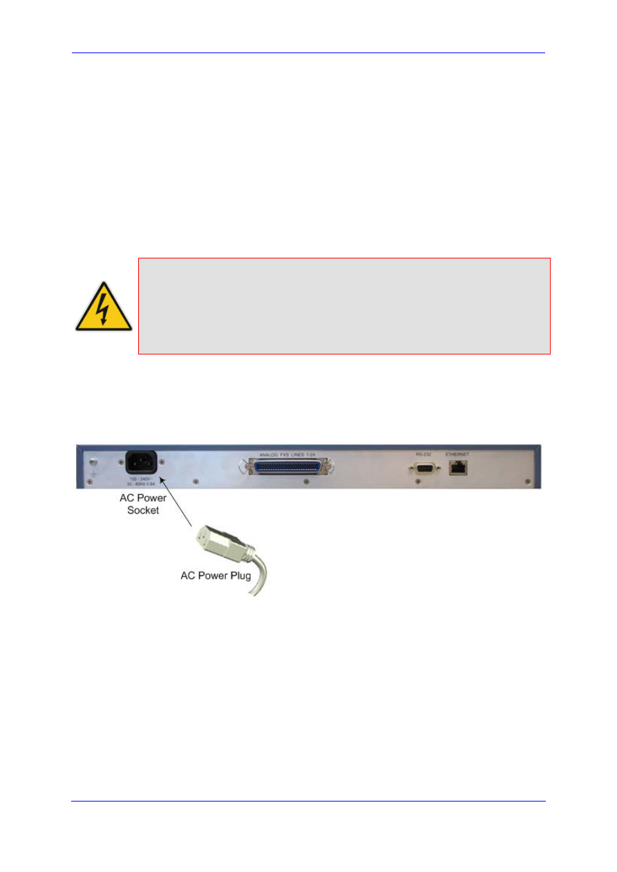
2.4.6
Connecting MP-11x to Power
MP-11x is powered from a standard alternating current (AC) electrical outlet.
Warnings:
•
The device must be connected only by professional service personnel.
•
Ensure that the device connects to an electrical socket outlet that
provides protective earthing (grounding). Prior to connecting power, refer
to the Regulatory Information document supplied with the device.
•
Use only the AC power cord supplied with the device.
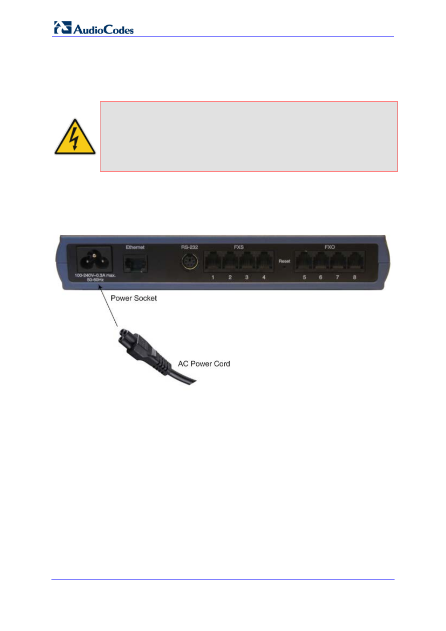
To connect MP-11x to the power supply:
1.
Connect the line socket of the AC power cord (supplied) to the device's AC power
socket (labeled 100-240V 0.3A ~50-60 Hz), located on the rear panel.
Figure 2-18: Connecting to the Power Supply
2.
Connect the plug at the other end of the AC power cord to a standard electrical outlet.
Version 6.6
21
April 2012
Hardware Installation Manual
3. MP-124 Hardware Installation
3
MP-124 Hardware Installation
This chapter describes the MP-124 hardware installation.
3.1
Physical Description
The subsections below provide a physical description of the MP-124 front and rear panels.
3.1.1
MP-124 Front Panel
The MP-124 front panel, shown in the figure below provides LEDs for indicating various
operating statuses, and a reset button.
Figure 3-1: MP-124 Front Panel
3.1.1.1 Reset Pinhole Button
The MP-124 reset pinhole button enables you to reset the device or restore the device to
factory default settings. For more information, refer to the User's Manual.
3.1.1.2 LEDs Description
The MP-124 LEDs are described in the table below.
Table 3-1: MP-124 Front-Panel LEDs Description
Label
Color
State
Function
Ready
Green
On
Device powered on, self-test OK.
Orange
Blinking
Software loading/initialization.
Red
On
Malfunction.
LAN
Green
On
Valid 10/100Base-TX Ethernet connection.
Red
On
Malfunction.
Control
Green
Blinking
Sending and receiving SIP messages.
-
Off
No traffic.
Data
Green
Blinking
Transmitting RTP packets.
Red
Blinking
Receiving RTP packets.
-
Off
No traffic.
Hardware Installation Manual
22
Document #: LTRT-59815
MediaPack Series
Label
Color
State
Function
Channels
Green
On
Telephone in off-hook position or ringing.
Red
On
Line malfunction.
-
Off
Normal.
3.1.2
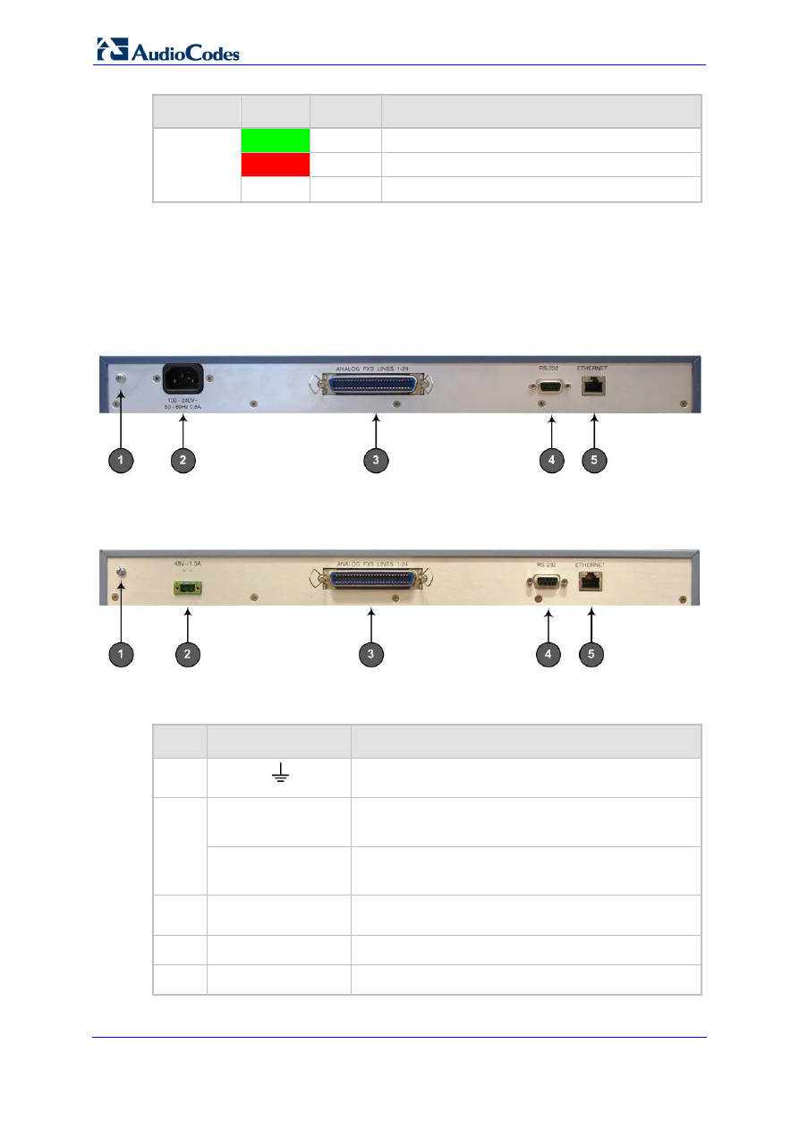
MP-124 Rear Panel
The rear panel of the MP-124 provides the port interfaces. The MP-124 is available as
either an AC-powered or DC-powered device.
AC-powered model:
Figure 3-2: Rear Panel of MP-124 AC Powered Model
DC-powered model:
Figure 3-3: Rear Panel of MP-124 DC Powered Model
The table below describes the MP-124 rear panel components.
Table 3-2: MP-124 Rear-Panel Description
Item #
Label
Component Description
1
Protective earthing screw (mandatory for all
installations). Accepts a 6-32 UNC screw.
2
100-250 V~50 - 60Hz
2A
AC power supply socket.
Note: Applicable only to the AC-powered model.
48V 1.3A
DC inlet for a DC terminal block.
Note: Applicable only to the DC-powered model.
3
ANALOG FXS
LINES 1–24
50-pin Telco connector for 1-24 analog lines.
4
RS-232
9-pin RS-232 port.
5
ETHERNET
10/100Base-TX Ethernet RJ-45 port.

Version 6.6
23
April 2012
Hardware Installation Manual
3. MP-124 Hardware Installation
The Ethernet LEDs are located in the RJ-45 socket. The table below describes these LEDs.
Table 3-3: MP-124 Rear-Panel Ethernet LEDs Description
Label
Color
State
Function
ETHERNET
Green
On
Valid 10/100Base-TX Ethernet connection.
Red
On
Malfunction.
3.2
Unpacking and Checking Package Contents
Follow the procedure below for unpacking the carton in which MP-124 is shipped.
To unpack MP-124:
1.
Open the carton and remove packing materials.
2.
Remove the MP-124 unit from the carton.
3.
Check that there is no equipment damage.
4.
Ensure that in addition to the MP-124 unit, the package contains the following items:
•
Only for AC-powered model: AC power cable
•
Only for DC-powered model: unwired DC terminal block with two crimping screws
•
Two short equal-length brackets and bracket-to-device screws for 19-inch rack
installation.
•
Regulatory Information document.
5.
Check, retain and process any documents.
6.
Notify AudioCodes or your local supplier of any damage or discrepancies.
Hardware Installation Manual
24
Document #: LTRT-59815
MediaPack Series
3.3
Mounting MP-124
MP-124 can be mounted in one of the following ways:
Desktop mounting – see 'Desktop Mounting' on page
Installed in a standard 19-inch rack – see '19-inch Rack Mounting' on page
3.3.1
Desktop Mounting
For MP-124 desktop mounting, no brackets are required. Simply place MP-124 on a
desktop in the required position.
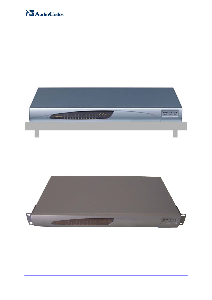
Figure 3-4: MP-124 Desktop Mounting
3.3.2
19-inch Rack Mounting
MP-124 can be installed in a standard 19-inch rack, by using two short, equal-length
brackets (supplied). MP-124 with attached brackets for rack installation is shown in the
figure below:
Figure 3-5: MP-124 with Brackets for Rack Installation
Version 6.6
25
April 2012
Hardware Installation Manual
3. MP-124 Hardware Installation
Rack Mount Safety Instructions
When installing the chassis in a rack, implement the following safety
instructions:
•
Elevated Operating Ambient - If installed in a closed or multi-unit rack
assembly, the operating ambient temperature of the rack environment
may be greater than room ambient. Therefore, consideration should be
given to installing the equipment in an environment compatible with the
maximum ambient temperature (Tma) of 40°C (104°F).
•
Reduced Air Flow - Installation of the equipment in a rack should be
such that the amount of air flow required for safe operation on the
equipment is not compromised.
•
Mechanical Loading - Mounting of the equipment in the rack should be
such that a hazardous condition is not achieved due to uneven
mechanical loading.
•
Circuit Overloading - Consideration should be given to the connection
of the equipment to the supply circuit and the effect that overloading of
the circuits might have on overcurrent protection and supply wiring.
Appropriate consideration of equipment nameplate ratings should be
used when addressing this concern.
•
Reliable Earthing - Reliable earthing of rack-mounted equipment should
be maintained. Particular attention should be given to supply connections
other than direct connections to the branch circuit (e.g., use of power
strips.)
To install MP-124 in a 19-inch rack:
1.
Remove the two screws located on one side of MP-124 (nearest the front panel).
2.
Insert the peg on one of the brackets into the third air vent down on the column of air
vents nearest the front panel.
3.
Swivel the bracket until the holes in the bracket align with the two empty screw holes
on MP-124.
4.
Use the supplied screws to attach the bracket to the side of MP-124.
5.
Repeat steps 1 through 4 to attach the second bracket to the other side of MP-124.
6.
Position MP-124 in the rack and line up the bracket holes with the rack frame holes.
7.
Use four standard rack screws (not supplied) to attach MP-124 to the rack.

Hardware Installation Manual
26
Document #: LTRT-59815
MediaPack Series
3.4
Cabling MP-124
This section describes the MP-124 cabling procedures:
Grounding (earthing) MP-124 – see 'Grounding MP-124' on page
Connecting to the Ethernet network – see 'Connecting MP-124 to the Ethernet
Network' on page
Connecting to FXS analog lines – see 'Connecting MP-124 to FXS Interface' on page
Serial connection to a computer – see 'Connecting MP-124 RS-232 Port to a PC' on
page
Connecting to the power supply – see 'Connecting MP-124 to Power' on page
Version 6.6
27
April 2012
Hardware Installation Manual
3. MP-124 Hardware Installation
3.4.1
Power Surge Protection and Grounding
This section discusses power surge protection and grounding of MP-124.
Warning:
•
Ensure that you connect MP-124 to an electrical socket outlet that
provides protective earthing (grounding). Prior to connecting power, refer
to the Regulatory Information provided in the User’s Manual.
For Finland: "Laite on liltettava suojamaadoituskoskettimilla varustettuun
pistorasiaan."
For Norway: "Apparatet rna tilkoples jordet stikkontakt."
For Sweden: "Apparaten skall anslutas till jordat uttag."
•
MP-124 is immune against power surge levels of up to 1 Kilovolts (KV) as
required by the following standards: IEC 61000-4-5, EN 55024, and EN
300386.
•
For installations where wires are routed outside the building, the
Telecommunication site must comply with ETS 300-253 “Earthing and
Bonding of Telecommunication Equipment in Telecommunication
Centers”.
•
Power surges above protection levels as required by EN 55024/EN
300386 may cause damage to MP-124.
•
MP-124 provides only Secondary Protection against power surges. In
deployments where the telephone lines are installed outside, you must
install Primary Protection against lightning. Only lightning protectors
recommended by AudioCodes must be used - specifically, manufactured
by Circa. Failing to install Circa primary surge protectors, failing to
comply with the grounding instructions or any other installation
instructions, may cause permanent damage to MP-124.
•
As most of the installation is the responsibility of the customer,
AudioCodes can assume responsibility for damage only if the customer
can establish that MP-124 does not comply to the standards specified
above (and MP-124 is within the hardware warranty period).
Note:
Proper grounding is crucial to ensure the effectiveness of the primary
protection devices against power surges. Therefore, both the primary
protector and MP-124 must be connected to the equipotential ground bus (in
electrical switch board) that is connected directly to the grounding of the
foundation reinforcement conductor.
Before installation, loop-testing grounding measurements must be done by a
certified electrician to verify the quality of the grounding connection. The
grounding impedance must not exceed 0.5 ohm.
Lightning is the transient passage of electrical current between a cloud and the surface of
the earth. Part of the lightning current can be carried inside a building from electrical lines
and analog and/or digital telephone lines located outside. This direct injection of lightning
current inside a building can cause significant damage to electronic circuits and equipment.
To protect MP-124 from these power surges, MP-124 must be connected to an external
lightning protector. You must use a lightning protector of the type CIRCA 4B3S-75
manufactured by CircaTelecom (
). The connection must be
made using the terminal fixture of the type CIRCA 2625QC/QC or 26100QC/QC.
Hardware Installation Manual
28
Document #: LTRT-59815
MediaPack Series
This fixture must be connected alongside or within the Main Distribution Frame (MDF). You
must connect the grounding connection of this electrical cabinet to the grounding bus of the
electrical circuit board, using AWG wires of at least 10mm
2
and maximum length of 3
meters.
MP-124 must be connected to the power surge protector using minimum 26-AWG wire
thickness.
MP-124 must be installed in the Telecommunication rack. MP-124 grounding screw must
be connected to the equipotential grounding bus bar located in the Telecommunication
rack, using a wire of 6mm
2
surface wire. This line must be connected to the equipotential
bus bar of the electrical circuit board located in the Telecommunication room, using a
stranded cable with surface area of 25 mm
2
. The length of this cable must be as short as
possible; no longer than 3 meters.
The MP-124 chassis is equipped with a protective earthing screw. Ensure that you connect
this to the grounding point using a suitable wire. Fasten the cable securely using a 6-32
UNC screw.
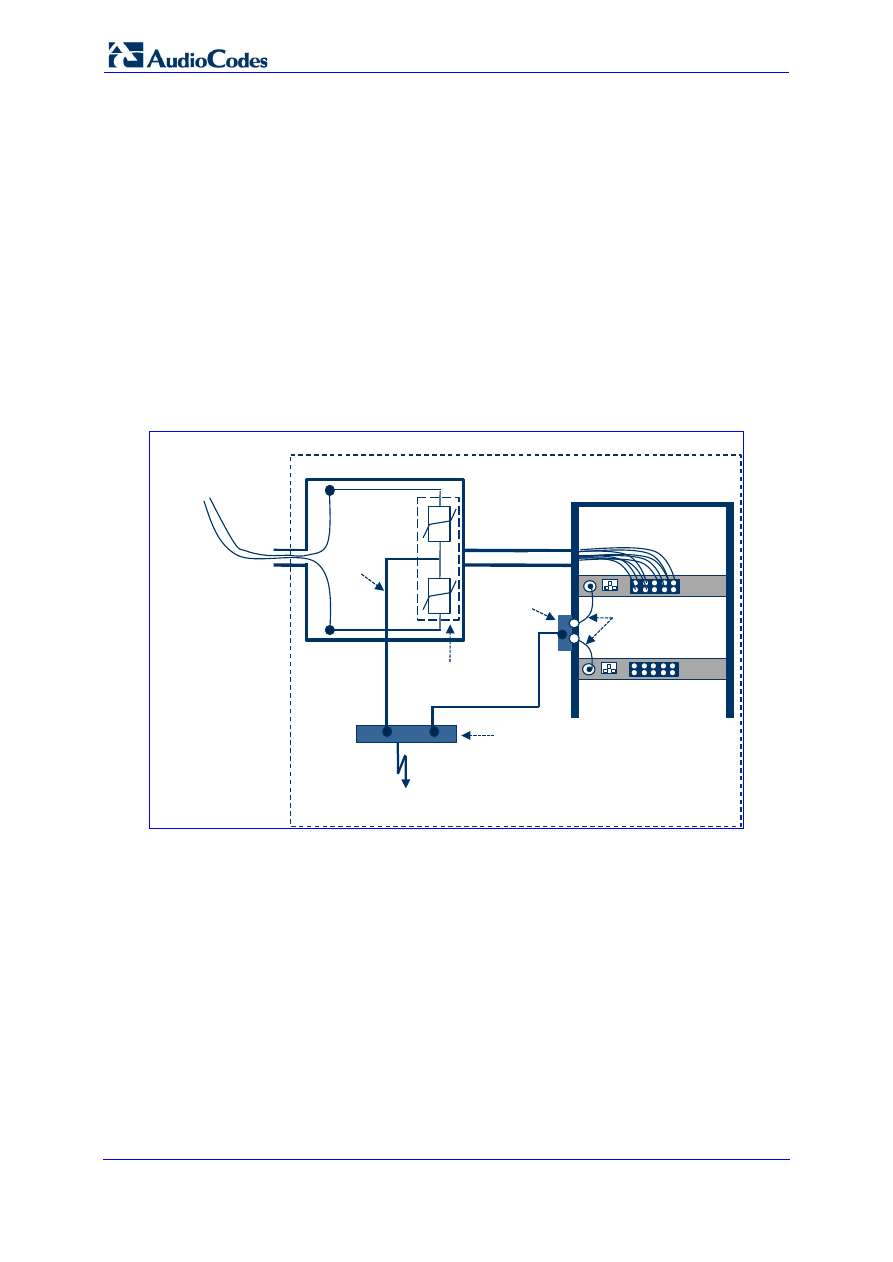
The figure below illustrates the connection method for grounding and lightning protector.
Figure 3-6: Grounding and Power Surge Protection
Telephone Lines
Outside Building
Main Distribution Frame (MDF)
To Foundation
Reinforcement/Ring Conductor (Ground)
Tip
Ring
26 AWG
MP-124
Equipment Rack
Telecommunication Room
MP-124
Stranded
Wire
10 mm
2
50-Pin Telco for
Telephone Lines
Stranded Wire
6 mm
2
Equipotential
Ground Bus Bar
Primary Lightning
Protection (CIRCA)
Equipotential Ground Bus
in Electrical Board
Version 6.6
29
April 2012
Hardware Installation Manual
3. MP-124 Hardware Installation
3.4.2
Connecting MP-124 to the Ethernet Network
The procedure below describes how to connect MP-124 directly to the Ethernet network.
This cabling requires a crossover Ethernet cable with the following RJ-45 connector
pinouts:
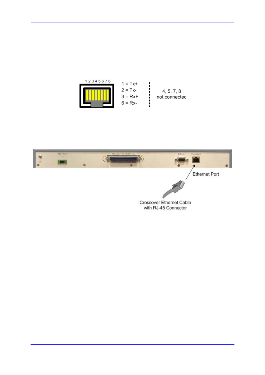
Figure 3-7: RJ-45 Connector Pinouts for Ethernet Connection
To connect MP-124 directly to the Ethernet network:
1.
Connect one end of a crossover RJ-45 Ethernet cable to the Ethernet port (labeled
ETHERNET).
Figure 3-8: Connecting to the Ethernet
2.
Connect the other end of the cable to the Ethernet network.
Hardware Installation Manual
30
Document #: LTRT-59815
MediaPack Series
3.4.3
Connecting MP-124 to FXS Interfaces
The MP-124 interfaces with the analog telephone interfaces by connecting to a main
distribution frame (MDF), using a 50-pin Telco cable.
MP-124 Safety Notice
To protect against electrical shock and fire, use a 26 AWG min wire to connect
analog FXS lines to the 50-pin Telco connector.
Warning:
To reduce noise interference, use a twisted pair Octopus cable that is
terminated on a metal-hooded 50-pin Telco connector.
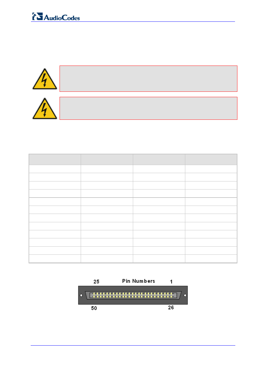
To connect MP-124 to FXS telephone interfaces:
1.
Wire the 50-pin Telco connectors according to the pinouts in the table below:
Table 3-4: 50-pin Telco Connector Pin Allocations
Phone Channel
Connector Pins
Phone Channel
Connector Pins
1
1/26
13
13/38
2
2/27
14
14/39
3
3/28
15
15/40
4
4/29
16
16/41
5
5/30
17
17/42
6
6/31
18
18/43
7
7/32
19
19/44
8
8/33
20
20/45
9
9/34
21
21/46
10
10/35
22
22/47
11
11/36
23
23/48
12
12/37
24
24/49
Figure 3-9: 50-pin Telco Connector
2.
Attach each pair of wires from a 25-pair Octopus cable (not supplied) to its
corresponding socket on the MDF adaptor block’s rear panel.
3.
Connect the wire-pairs at the other end of the cable to a male 50-pin Telco connector
(not supplied).
Version 6.6
31
April 2012
Hardware Installation Manual
3. MP-124 Hardware Installation
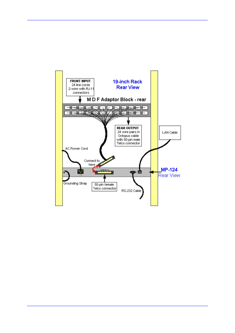
4.
Insert and fasten the male connector to the female 50-pin Telco connector on the
MP-124 rear panel (labeled Analog FXS Lines 1-24).
5.
Connect the telephone lines from the MDF adaptor block to a fax machine, modem, or
telephones by inserting each RJ-11 connector on the 2-wire line cords of the POTS
phones into the RJ-11 sockets on the front of an MDF adaptor block, as shown in the
figure below.
Figure 3-10: MP-124 in a 19-inch Rack with MDF Adaptor
Hardware Installation Manual
32
Document #: LTRT-59815
MediaPack Series
3.4.4
Connecting MP-124 to a Computer for Serial Communication
The procedure below describes how to connect the MP-124 to a computer for serial RS-232
communication.
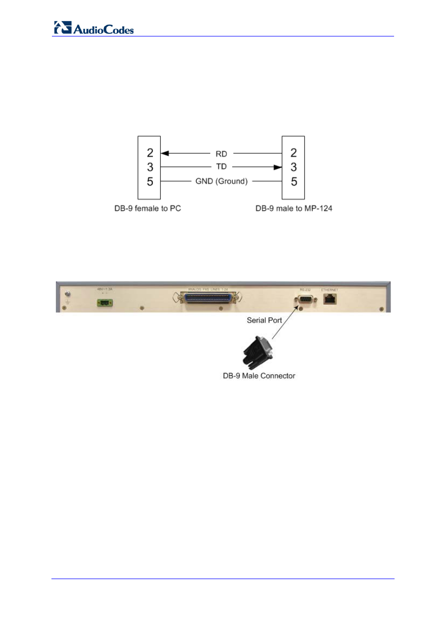
This cabling uses a standard, straight-through cable with DB-9 connectors on either end,
with the following connector pinouts:
Figure 3-11: MP-124 RS-232 Connector Pinouts
.
To connect MP-124 to a computer for serial communication:
1.
Connect the DB-9 connector on one end of the cable to the MP-124 RS-232 port
(labeled RS-232).
Figure 3-12: MP-124 Serial Cabling
2.
Connect the DB-9 connector at the other end of the cable to either the COM1 or COM2
RS-232 communication port on your computer.
Once you power-up MP-124, the Ready and LAN LEDs on the front panel light up green
(after a self-testing period of about a minute). Any malfunction in the startup procedure
changes the Ready LED to red.
For information on establishing a serial communication link with MP-124, refer to the User's
Manual.
Version 6.6
33
April 2012
Hardware Installation Manual
3. MP-124 Hardware Installation
3.4.5
Connecting MP-124 to Power
MP-124 can be powered either from a standard AC electrical outlet or a 48-VDC power
supply. The power configuration depends on the ordered MP-124 model.
After powering-up MP-11x, the Ready and Power LEDs on the front panel light up green
(after a self-testing period of about two minutes). Any malfunction in the startup procedure
changes the Fail LED to red and the Ready LED is turned off.
3.4.5.1 AC Power Supply
This section describes cabling of the MP-124 model for AC power.
Warnings:
•
The device must be connected only by professional service personnel.
•
Ensure that the device connects to an electrical socket outlet that
provides protective earthing (grounding). Prior to connecting power, refer
to the Regulatory Information document supplied with the device.
•
Use only the AC power cord supplied with the device.
To connect MP-124 to the AC power supply:
1.
Connect the line socket of the AC power cord (supplied) to the device's AC power
socket (labeled 100-250 V~50 - 60Hz 2A), located on the rear panel.
Figure 3-13: AC Power Cabling
2.
Connect the plug at the other end of the AC power cord to a standard electrical outlet.
Hardware Installation Manual
34
Document #: LTRT-59815
MediaPack Series
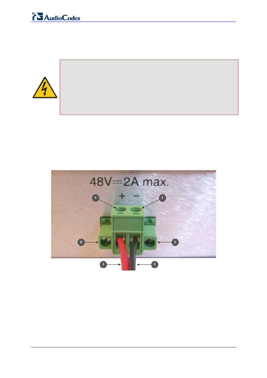
3.4.5.2 DC Power Supply
This section describes cabling of the MP-124 model for 48-VDC power supply.
MP-124 DC Safety Notice
When connecting MP-124 to a DC power supply, ensure that you adhere to
the following safety guidelines:
•
Connect the device to a safety extra-low voltage (SELV) source that is
sufficiently isolated from the mains.
•
Connect the device permanently to earth (ground) using the earthing
(grounding) stud located on its’ rear panel (see 'Grounding MP-124' on
page
To connect MP-124 to a DC power supply:
1.
Insert two 18 AWG wires into the supplied DC terminal block (ensure correct polarity),
and then fasten the two screws located directly above each wire block.
2.
Insert the DC terminal block into the DC inlet on the MP-124 rear panel, and then
secure it to the device by fastening the two adaptor-to-panel screws located on the
terminal block.
Figure 3-14: Wired DC Power Terminal Block Connected to MP-124
Legend:
1.
Two integral screws for wire connection to the DC terminal block.
2.
Two integral screws for connecting the DC terminal block to the MP-124 DC inlet.
3.
Two 18 AWG wires (positive and negative polarity).
3.
Connect the other end of the DC cable to a 48-VDC power supply.

Version 6.6
35
April 2012
Hardware Installation Manual
3. MP-124 Hardware Installation
Reader's Notes

Installation Manual Ver. 6.6
www.audiocodes.com
Document Outline
- MP-1xx Hardware Installation Manual
- Table of Contents
- List of Figures
- List of Tables
- Notices
- 1 Introduction
- 2 MP-11x Hardware Installation
- 3 MP-124 Hardware Installation
Wyszukiwarka
Podobne podstrony:
LTRT 59806 MP 11x & MP 124 SIP Fast Track Guide
LTRT 52911 MP 11x SIP Quick Guide
LTRT 52906 MP 11x SIP Fast Track Guide
Next Gen VoIP Services and Applications Using SIP and Java
14 Estimating and Bidding Fiber Optic InstallationX
The US Army and Marine Corps Counterinsuring field manual
Demidov A S Generalized Functions in Mathematical Physics Main Ideas and Concepts (Nova Science Pub
MP W 06N
MP W 04N
R 4 2b mp
MP W 07N dodatek
R 4 1 mp
MP 6
MP 5
więcej podobnych podstron