Perimeter Guarding with Embedded Safety Module
SCS20/0514
2014-06-26
- 1 -
Light curtain / Contactor
Cat.4 PL e, SIL 3 / Stop Category 0
Function:
•
Safety-related stop function initiated by safety light curtain (ESPE
Type 4 according to EN/IEC 61496-1 and EN/IEC 61496-2).
•
An interruption of the detection field causes the safety outputs to
open. The deactivation of the safety outputs results in the switching-
off of the motor power supply by means of the contactors (K3 and
K4) to help to prevent possible hazardous movements or states.
•
The safety light curtain receivers and outputs are cyclically tested
and monitored by the safety light curtain to detect possible failures.
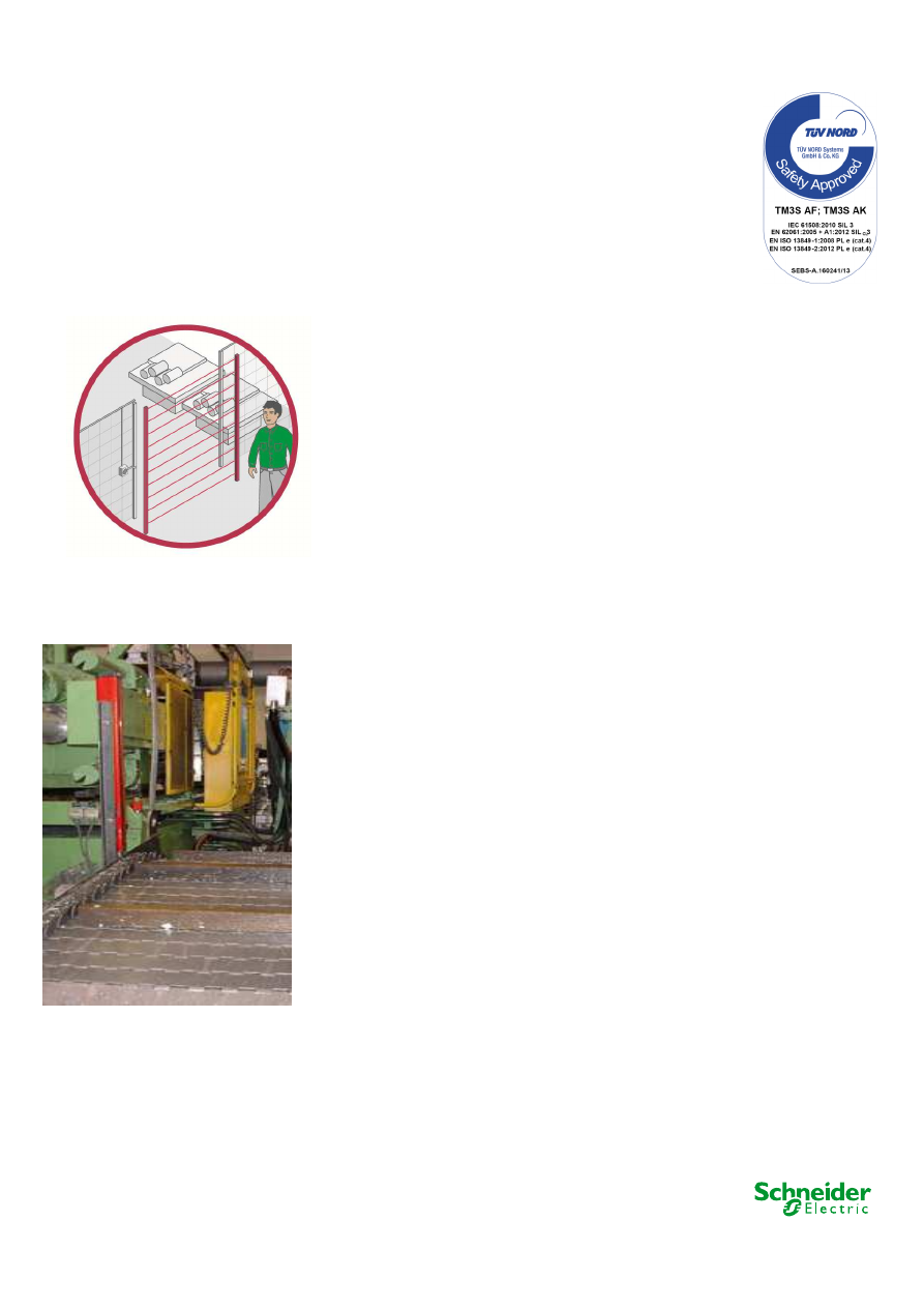
Typical applications:
Palletizing stations with automatic control system where pallets would
pass frequently through the hazardous area.
Design:
•
The safety function employs well-tried safety principles and is robust
in the event of one component failure by means of two contactors
(K3 and K4) and a light curtain (B1 and B2).
•
A contactor fault is detected by the safety module at the next
demand upon the safety function by the restart interlock pushbutton.
•
The start function (S) must be located outside the hazardous area
and at a point from which the potential danger is visible. It can be
realized by the PLC as well.
•
The light curtain (B1 and B2) has direct opening semiconductor
outputs in accordance with IEC 61496-1, 2 and EN 61496-1 and is
regarded as well-tried component.
•
The safety module satisfies the requirements for performance level
up to PL e according to EN ISO 13849-1 and safety integrity level
SIL
CL
3 according to EN/IEC 62061.
•
The contactors (K3 and K4) have mirror contacts in accordance with
EN/IEC 60947-4-1, meaning that the normally closed auxiliary
contacts cannot be in the closed state unless the main poles are
open. They are also considered as well-tried components.
•
Protection against overcurrent must be provided in accordance with
EN/IEC 60947-4-1.
Perimeter Guarding with
SCS20/0514
2014-06-26
Safety Chain Products:
•
Safety light curtain -
Preventa XU
•
Safety Module -
Modicon TM3SAK6R(G)
•
Contactor -
TeSys D
Related Products:
•
Switches, pushbuttons -
Harmony XB4
•
Switch mode Power supply -
Phaseo ABL8
•
Modular beacon and tower light -
B1
Perimeter Guarding with Embedded Safety Module
- 2 -
Preventa XUSL
Modicon TM3SAK6R(G)
Harmony XB4
Phaseo ABL8
-
Harmony XVB
B1
B2
Safety Module
SCS20/0514D
Perimeter Guarding with Embedded Safety Module
SCS20/0514
2014-06-26
- 3 -
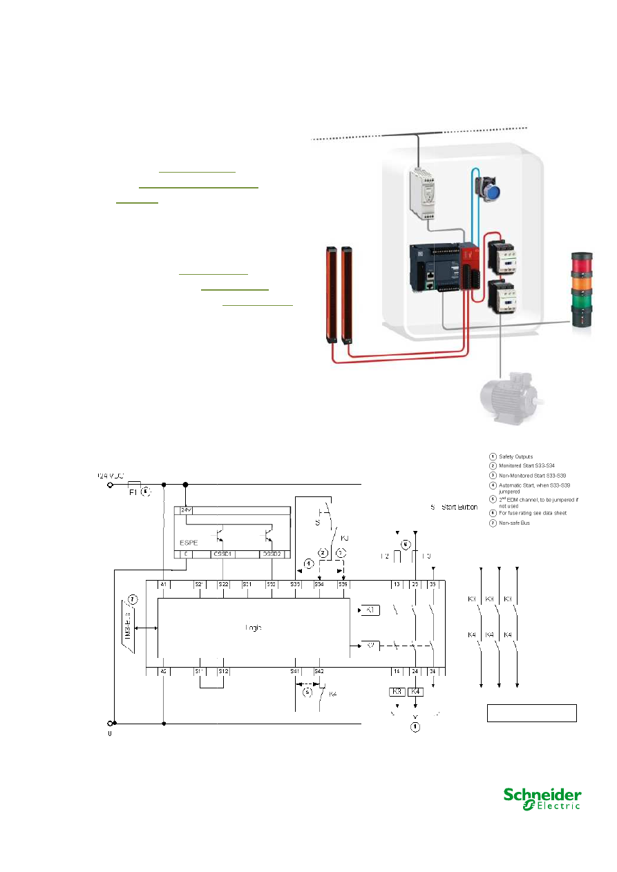
Chain structure:
•
The circuit diagram SCS20/0514D is a conceptual schematic diagram
and is limited to present the safety function with only the relevant safety
components.
•
For the designated architecture of category 4, two redundant channels
are implemented. This light curtains family offers muting function too.
•
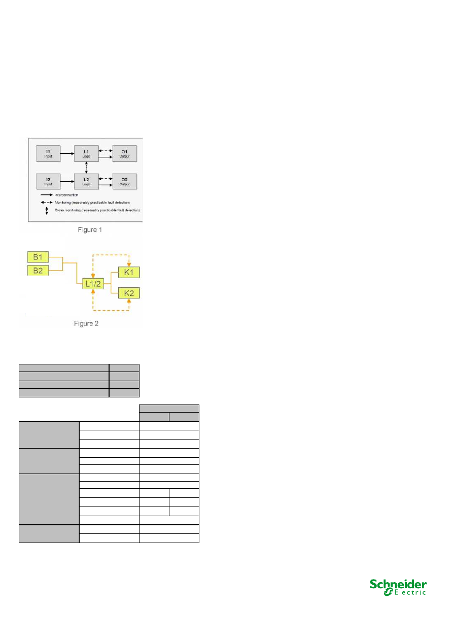
The circuit arrangement can be divided into three function blocks per
channel with the input (I), logic (L) and output (O) blocks on each
channel.
•
The possibility of fault detection by monitoring the outputs is indicated by
the broken lines (see figure 1).
•
The functional channel can be represented by a light curtain actuating
two semiconductor switches (i.e. B1 and B2) that would correspond to
the input (see figure 2).
•
The safety module (TM3SAK6R(G)) corresponds to the logic block
(L1/L2), which maintains the internal redundancy of the safety circuits
required for this architecture.
•
The output block is represented by two redundant contactors (K3 and K4)
that are monitored by the logic block (safety module) to detect any failure.
•
The complete wiring must be in accordance to EN 60204-1 and the
necessary means to avoid short circuits has to be provided (EN ISO
13849-2 Table D.4).
•
The start functionality (S) can be realized as well by means of a PLC
output. Re-start is not considered safety relevant operation. If the light
curtain is interrupted re-start has no effect.
Safety level calculation:
•
A required performance level (PL
r
) must be specified for
each intended safety function following a risk evaluation.
The performance level (PL) attained by the control system
must be validated by verifying if it is greater than or equal
to the PL
r
.
•
At 220 working days per year, 12 working hours per day
and a cycle time of 1 minute, the number of operations
(n
op
) would be 158 400 per year.
•
Mean time to dangerous failure (MTTF
d
) values exceeding
100 years will be limited to this value in order for the
component reliability not to be overstated in comparison
with the other main influencing variables such as the
architecture or tests.
Light curtain
60
12
220
158400
Channel 1
Channel 2
Logic TM3SAK6R(G)
Output TeSys D
100
100
99%
99%
65
65
Safety function
PFH
d
resulting (1/h)
7,87E-08
PL attained
e
Number of operations per year
Values
Input device XUSL
4
4
MTTF
d
resulting (years)
DC
avg
CCF
PFH
d
resulting (1/h)
2,47E-08
PFH
d
resulting (1/h)
5,00E-09
PL
e
Category
PFH
d
resulting (1/h)
4,90E-08
PL
e
Category
4
PL
e
Category
Cycle time (s)
Number of hours' operation per day
Number of days' operation per year

Perimeter Guarding with Embedded Safety Module
SCS20/0514
2014-06-26
- 4 -
•
These values are therefore limited to 100 years ("high").
•
A PFH
d
value of 5 x10
-9
is stated for the safety module
•
(TM3SAK6R(G)). This value comes directly from the
safety device data and it is certified by an accepted
standards body.
•
For the redundant contactors K3 and K4, the B10 value
corresponds under nominal load to an electrical lifetime of
10 000 000 switching cycles. If 50% of failures are
assumed to be dangerous, the B10
d
value is 20 000 000
operations. With the assumed value for n
op
, it results in a
MTTF
d
of 1262,6 years for each component. These values
are therefore limited to 100 years ("high").
•
The combination of channel 1 and channel 2 results in a
DC of 99% (high) as K3 and K4 are monitored by the
safety logic.
•
Measures against common cause failures (Annex F of EN
ISO 13849-1) must attain at least 65 points (i.e.
separation (15), overvoltage protection etc. (15) and
environmental conditions (25+10)).
•
The safety-related control system corresponds to category
4 with high MTTF
d
. The complete functional safety chain
results in average probability of dangerous failure (PFH
d
)
of 7.87 x 10
-8
. This corresponds to PL e and SIL 3.
ENVIRONM ENTA L
CONDITIONS
Light curtain P reventa
XUSL o utside o f a cabinet
Safety mo dule
TM 3SA K6R/G and
Co ntacto r - TeSys D
inside a cabinet
Degree o f pro tectio n
acco rding to IEC/EN
60529
Terminals:
IP 20
Enclo sure:
IP 20
A mbient o perating
temperature (ho rizo ntal
installatio n)
-10…55 °C
– 10...+ 55 °C (+ 14...+ 130 °F)
Fo r use in max. height
abo ve sea o f
2000 m (6560 ft)
Sto rage temperature
-25...75 °C
- 40...+ 70 °C (- 40...158 °F)
Fo r sto rage in max.
relative humidity o f
<= 95 % witho ut
co ndensatio n
95 %, no n co ndensing
Fo r sto rage in height
abo ve sea level o f
0…3000 m (0...9842 ft)
Overvo ltage catego ry
III (4 kV)
P o llutio n degree
2
Rated insulatio n vo ltage
acco rding to IEC/EN
60664-1
~ 300 V
Supply vo ltage
SELV/P ELV c 24 V – 15/
+20 %
M ax. pro tectio n
4 A fuse gG
Rated po wer
B us 5 VDC
0.2 W
External Supply 24 VDC
2.4 W
M ax. current per o utput
path
6:00 A M
The sum o f simultaneo us
currents o n all o f the
o utputs is limited to
Σ
Ith
≤
18 A
P ro tectio n o f o utputs
max.: 4 A fuse gG o r 6 A
fast blo w
M aximum switching
capacity o f o utputs
A C-15
~ 230 V, 5 A
DC-13
24 VDC, 4 A
General
IP 65
Supply
24 V DC
(+/- 20%)
Output circuit
Wyszukiwarka
Podobne podstrony:
18 GuardMonitoring TM3 XCS TeSysD 4e3 sc0
17 EmergencyStop TM3 XALK TeSysD 4e3 sc0
19 PerimeterGuarding TM3 XUSL ATV32 3d2 sc1
16 EmergencyStop TM3 XALK TeSysD 3d2 sc0
Zawal serca 20 11 2011
20 Rysunkowa dokumentacja techniczna
Prezentacja 20 10
20 2id 21226 ppt
20 H16 POST TRANSFUSION COMPLICATIONS KD 1st part PL
20 Tydzień zwykły, 20 środa
3 Analiza firmy 2015 (Kopia powodująca konflikty (użytkownik Maciek Komputer) 2016 05 20)
Prezentacja 20
plik (20)
20
20 Księga Przypowieści Salomona
01 Top 20 ports
cw 20 Instrukcja
chojnicki 1999 20 problemy GP
więcej podobnych podstron