Emergency Stop with Embedded Safety
SCS16/0514
2014-06-26
Emergency Stop Pushbutton / Contactor
Cat.3 PL d, SIL 2 / Stop Category 0
Emergency Stop with Embedded Safety Module
- 1 -
Emergency Stop Pushbutton / Contactor
Cat.3 PL d, SIL 2 / Stop Category 0
Function:
•
Safety-related stop function initiated by
pushbutton to minimize the consequences of
event.
•
The pushing of emergency stop pushbutton is detected from
opening contacts, which are checked by the safety module.
•
Opening these contacts causes the deactivation of the safety
module outputs (stop category 0 according to EN/IEC 602
which results in a switch-off of the motor power supply to
minimize hazard in case of emergenc
contactors (K3 and K4).
Typical applications:
Machine-tools or similar machines with low inertia (no rundown time),
where the access to the hazardous area is limited to maintenance
interventions.
Design:
•
The safety function employs well-tried safety principles and is
robust in the event of one component failure by me
contactors (K3 and K4) and an emergency pushbutton (
•
A contactor fault is detected by the safety module at the next
demand upon the safety function by the restart interlock
pushbutton.
•
The start button (S2) must be located outside the hazardous area
and at a point from which the potential danger is visible.
•
The emergency pushbutton (S1) has direct opening action in
accordance with EN/IEC 60947-5-1 and is regarded as well
component.
•
The safety module satisfies the requirements
level up to PL d according to EN ISO 13849
according to EN/IEC 62061.
•
The contactors (K3 and K4) have mirror contacts in accordance
with EN/IEC 60947-4-1, meaning that the normally closed
auxiliary contacts cannot be in the closed state unless the main
poles are open. They are also considered as well
components.
•
Protection against overcurrent must be provided in accordance
with EN/IEC 60947-4-1.
Module
related stop function initiated by emergency stop
pushbutton to minimize the consequences of possibly harmful
The pushing of emergency stop pushbutton is detected from
opening contacts, which are checked by the safety module.
Opening these contacts causes the deactivation of the safety
module outputs (stop category 0 according to EN/IEC 60204-1),
off of the motor power supply to
minimize hazard in case of emergency by means of the
tools or similar machines with low inertia (no rundown time),
he hazardous area is limited to maintenance
tried safety principles and is
robust in the event of one component failure by means of two
) and an emergency pushbutton (S1).
actor fault is detected by the safety module at the next
demand upon the safety function by the restart interlock
(S2) must be located outside the hazardous area
and at a point from which the potential danger is visible.
1) has direct opening action in
1 and is regarded as well-tried
The safety module satisfies the requirements for performance
according to EN ISO 13849-1 and SIL
CL
2
) have mirror contacts in accordance
1, meaning that the normally closed
auxiliary contacts cannot be in the closed state unless the main
poles are open. They are also considered as well-tried
Protection against overcurrent must be provided in accordance
Emergency Stop with Embedded Safety Module
SCS16/0514
2014-06-26
- 2 -
Safety Chain Products:
•
Safety switches -
Preventa XALK
•
Safety Module -
Modicon TM3SAC5R(G)
•
Contactor -
TeSys D
Related Products:
•
Switches, pushbuttons, emergency stop -
Harmony XB4
•
Switch mode Power supply -
Phaseo ABL8
•
Modular beacon and tower light -
Harmony XVB
1
2
Safety Outputs
K2
K1
13
23
33
14
24
34
T
M
3
-B
u
s
A1
A2
Y1
Y2
Logic
+24 VDC
0
K4
K3
K3
K3
K4
K4
K3
K4
K3
K4
S2
S1
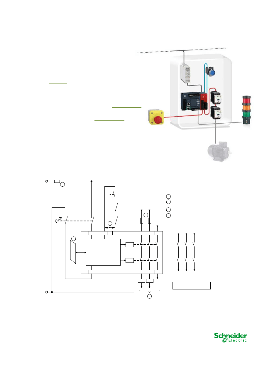
S1: Emergency Stop
S2: Start Button
1
Automatic Start, when Y1-Y2
jumpered
2
3
3
For fuse rating see data sheet
F1
F2
F3
3
4
4
Non-safe Bus
SCS16/0514D
Emergency Stop with Embedded Safety Module
SCS16/0514
2014-06-26
- 3 -
Chain structure:
•
The circuit diagram SCS16/0514D is a conceptual schematic diagram
and is limited to present the safety function with only the relevant safety
components.
•
For the designated architecture of category 3, two redundant channels
are implemented.
•
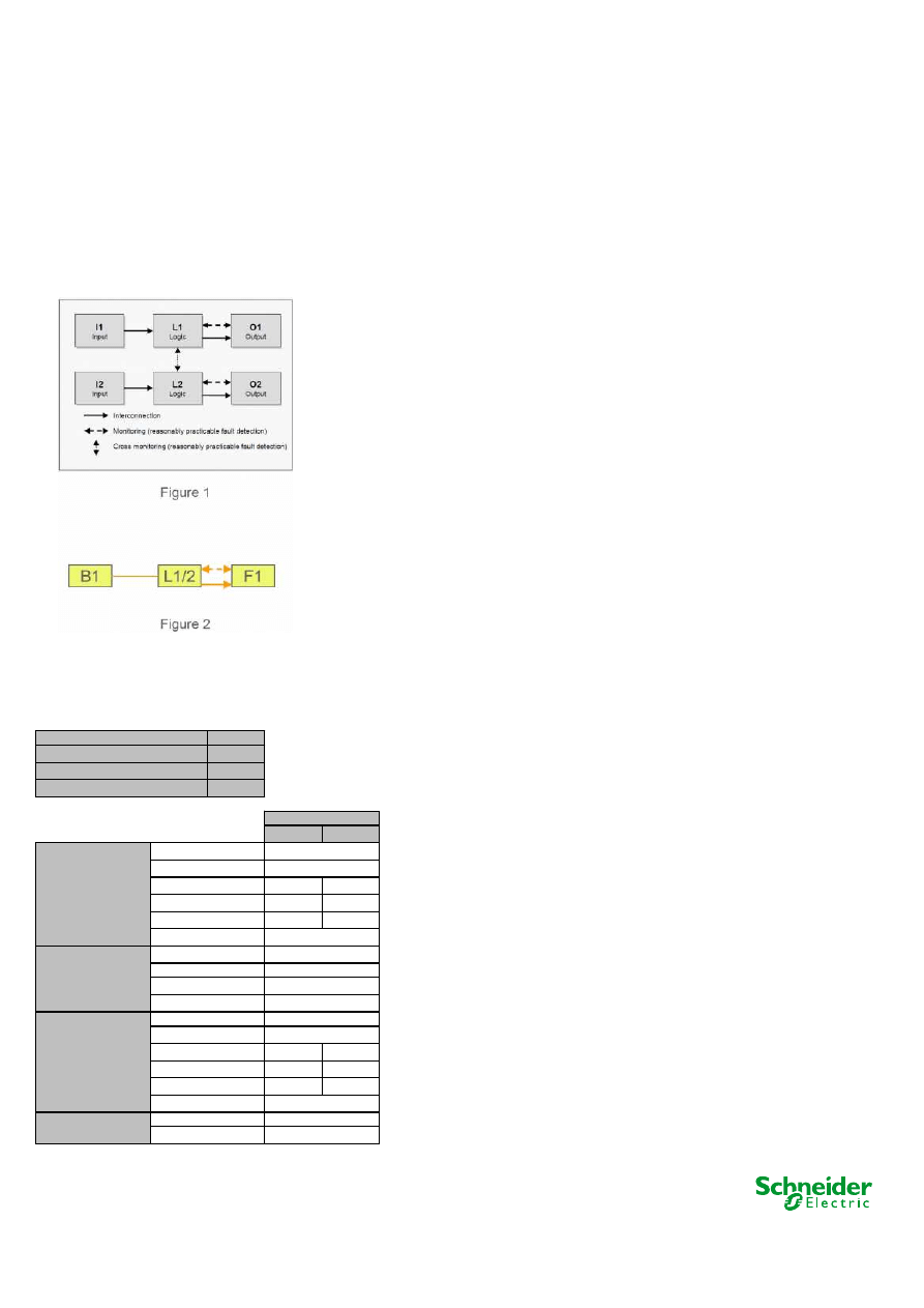
The circuit arrangement can be divided into three function blocks per
channel with the input (I), logic (L) and output (O) blocks on each
channel.
•
The possibility of fault detection by monitoring the outputs is indicated by
the broken lines (see figure 1).
•
The functional channel can be represented by a single emergency
pushbutton (i.e. B1) that would correspond to the input (see figure 2).
•
The safety module (TM3SAC5R(G)) corresponds to the logic block
(L1/L2), which maintains the internal redundancy of the safety circuits
required for this architecture.
•
The output block is represented by two redundant contactors (K3 and K4)
that are monitored by the logic block (safety module) to detect any failure.
•
The complete wiring must be in accordance to EN 60204-1 and the
necessary means to avoid short circuits has to be provided (EN ISO
13849-2 Table D.4).
Safety level calculation:
•
A required performance level (PL
r
) must be specified for each
intended safety function following a risk evaluation. The
performance level (PL) attained by the control system must
be validated by verifying if it is greater than or equal to the
PL
r
.
•
The emergency stop push button is operated once a month.
•
Mean time to dangerous failure (MTTF
d
) values exceeding
100 years will be limited to this value in order for the
component reliability not to be overstated in comparison with
the other main influencing variables such as the architecture
or tests.
•
A B10
d
value of 1 500 000 cycles is stated for the mechanical
aspects of S1. In accordance with the assumed n
op
value, the
MTTF
d
would be 4 090 909 years.
•
This value is therefore limited to 100 years ("high").
2592000
12
220
3,67
Channel 1
Channel 2
100
100
95%
95%
65
65
Logic TM3SAC5R(G)
Output TeSys D
PL
e
Category
4
MTTF
d
resulting (years)
100
100
DC
avg
99%
99%
CCF
75
75
PFH
d
resulting (1/h)
2,47E-08
Safety function
PL attained
d
PFH
d
resulting (1/h)
6,25E-08
DC
95%
e
4
3
d
3,28E-08
5,00E-09
PFH
d
Category
Input device XALK
PL
PFH
d
resulting (1/h)
CCF
PL
Category
DC
avg
MTTF
d
resulting (years)
Cycle time (s)
Number of hours' operation per day
Number of days' operation per year
Number of operations per year
Values
Emergency Stop with Embedded Safety Module
SCS16/0514
2014-06-26
- 4 -
•
A PFHd value of 5 x 10⁻⁹ is stated for the safety module
(TM3SAC5R(G)). This value comes directly from the safety
device data and it is certified by an accepted standards body.
•
For the redundant contactors K3 and K4, the B10 value
corresponds under nominal load to an electrical lifetime of
1 000 000 switching cycles. If 73% of failures are assumed to
be dangerous, the B10
d
value is 1 369 863 operations. With
the assumed value for n
op
, it results in a MTTF
d
of 3 735 990
years for each component. These values are therefore
limited to 100 years ("high").
•
Measures against common cause failures (Annex F of EN
ISO 13849-1) must attain at least 65 points (i.e. separation
(15), overvoltage protection etc. (15) and environmental
conditions (25+10)).
•
The safety-related control system corresponds to category 3
with high MTTF
d
. The complete functional safety chain
results in average probability of dangerous failure (PFH
d
) of
6.25 x 10
-8
.
•
This combination of safety devices allows PL d and SIL 2.
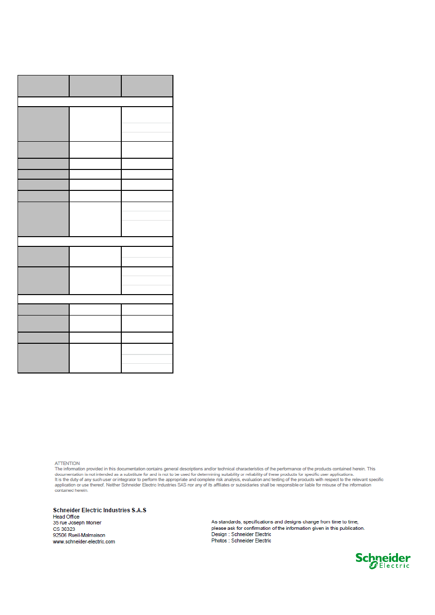
ENVIRONM ENTA L
CONDITIONS
Emergency P ush B utto n
P reventa XA LK o utside o f
a cabinet
Safety mo dule
TM 3SA C5R/G and
Co ntacto r - TeSys D
inside a cabinet
Degree o f pro tectio n
acco rding to IEC/EN
60529
Terminals:
IP 20
Enclo sure:
IP 20
A mbient o perating
temperature (ho rizo ntal
installatio n)
-25...70 °C
– 5...+ 55 °C (+ 14...+ 130 °F)
Fo r use in max. height
abo ve sea o f
2000 m (6560 ft)
Sto rage temperature
-40...70 °C
- 40...+ 70 °C (- 40...158 °F)
Fo r sto rage in max.
relative humidity o f
95 %, no n co ndensing
Fo r sto rage in height
abo ve sea level o f
0…3000 m (0...9842 ft)
Overvo ltage catego ry
III (4 kV)
P o llutio n degree
2
Rated insulatio n vo ltage
acco rding to IEC/EN
60664-1
~ 300 V
Supply vo ltage
SELV/P ELV c 24 V – 15/
+20 %
M ax. pro tectio n
4 A fuse gG
Rated po wer
B us 5 VDC
0.2 W
External Supply 24 VDC
2.4 W
M ax. current per o utput
path
6:00 A M
The sum o f simultaneo us
currents o n all o f the
o utputs is limited to
Σ
Ith
≤
18 A
P ro tectio n o f o utputs
max.: 4 A fuse gG o r 6 A
fast blo w
M aximum switching
capacity o f o utputs
A C-15
~ 230 V, 5 A
DC-13
24 VDC, 4 A
Output circuit
General
IP 65
Supply
Wyszukiwarka
Podobne podstrony:
17 EmergencyStop TM3 XALK TeSysD 4e3 sc0
18 GuardMonitoring TM3 XCS TeSysD 4e3 sc0
20 PerimeterGuarding TM3 XUSL TeSysD 4e3 sc0
19 PerimeterGuarding TM3 XUSL ATV32 3d2 sc1
Idealny 1 16 by emergency69
Sld 16 Predykcja
Ubytki,niepr,poch poł(16 01 2008)
16 Metody fotodetekcji Detektory światła systematyka
wyklad badania mediow 15 i 16
RM 16
16 Ogolne zasady leczenia ostrych zatrucid 16903 ppt
Wykład 16 1
(16)NASDAQid 865 ppt
16 2id 16615 ppt
Temat6+modyf 16 05 2013
bn 16
16 Tydzień zwykły, 16 wtorek
więcej podobnych podstron