Doc. No. : 2101 2273 16 62
TML – Diagnostic Manual A-ECU
Version : 1
Project :
Copyright © with TATA MOTORS
This document must not be used in any way, such as copying and redistributing to third parties, without our consent
Page 1 of 27
Author : TML
Dept : ERC-E&E
D
D
i
i
a
a
g
g
n
n
o
o
s
s
t
t
i
i
c
c
M
M
a
a
n
n
u
u
a
a
l
l
f
f
o
o
r
r
A
A
-
-
E
E
C
C
U
U
PURPOSE :
This document details the Diagnostic Procedure for the A-ECU used in Indica ,
Indigo, Marina Diesel BSII vehicles
Doc. No. : 2101 2273 16 62
TML – Diagnostic Manual A-ECU
Version : 1
Project :
Copyright © with TATA MOTORS
This document must not be used in any way, such as copying and redistributing to third parties, without our consent
Page 2 of 27
Author : TML
Dept : ERC-E&E
NOTE : This document is subject to change based on the A-ECU Hardware & software
changes
R
R
e
e
v
v
i
i
s
s
i
i
o
o
n
n
H
H
i
i
s
s
t
t
o
o
r
r
y
y
Prepared By
Approved By
Date
Reason For Changes
Page No. for
Changes
Ver.
Mr. V.Ashok Kumar
Mr.Vaidya
20/06/07
New release
1.00
Doc. No. : 2101 2273 16 62
TML – Diagnostic Manual A-ECU
Version : 1
Project :
Copyright © with TATA MOTORS
This document must not be used in any way, such as copying and redistributing to third parties, without our consent
Page 3 of 27
Author : TML
Dept : ERC-E&E
1. Scope …………………………………………………………… ………. 3
2. List of Fault Codes ……………………………………………………….. 4
3. Trouble-shooting with fault-codes ………………………………………..7
3.1 Fault Code 11 details …………………………………………………… 8
3.2 Fault Code 12 details ………………………………………………………. 9
3.3 Fault Code 13 details ………………………………………………………..10
3.4 Fault Code 14 details ………………………………………………………..11
3.5 Fault Code 15 details ………………………………………………………..12
3.6 Fault Code 16 details ………………………………………………………..13
3.7 Fault Code 17 details ………………………………………………………..14
3.8 Fault Code 18 details ………………………………………………………..15
3.9 Fault Code 21 details ………………………………………………………..16
3.10 Fault Code 22 details ………………………………………………………17
3.11 Fault Code 23 details ………………………………………………………18
3.12 Fault Code 24 details ……………………………………………………….19
3.13 Fault Code 27 details ………………………………………………………20
3.14 Fault Code 28 details ……………………………………………………….21
3.15 Fault Code 29 details ……………………………………………………….22
3.16 Table of Symptoms ……………………………………………………….23
Appendix A - ECU Pin Out ……………………………………………………...24
Appendix B – Circuit schematic ………………………………………………… 25
Appendix C – Diagnostic connector Location ……………………………………26
Contents. Page No.
Doc. No. : 2101 2273 16 62
TML – Diagnostic Manual A-ECU
Version : 1
Project :
Copyright © with TATA MOTORS
This document must not be used in any way, such as copying and redistributing to third parties, without our consent
Page 4 of 27
Author : TML
Dept : ERC-E&E
1.0 Scope:
This manual is intended as a trouble-shooting aid for AECU based system to be used by service
technicians. Section 2 lists various fault codes issued by AECU and how they are to be read.
Section 3 explains in detail trouble-shooting flow charts for each of the fault codes. Appendices
at the end include AECU pin-out and schematic diagram along with diagnostic enable connector
location.
2.0 A ECU Fault codes:
Sr.
No.
Fault Description
Code
1 Temperature
Sensor
Open
11
2 Temperature
Sensor
Short
12
3
Throttle Lever Potentiometer
Centre/Supply point open
13
4
Throttle Lever Potentiometer Gnd
point open
14
5
Loss Of Engine Speed Signal
15
6
Glow Plug Unit/Glow Plugs Faulty
7
GP ON Command or F/B Wire Open
16
8 GPR
Relay
Stuck
17
9
GPR Command line shorted to
supply
18
10
GP ON Lamp Shorted to Supply
21
11
GP ON Lamp Open/Wire Open
22
12
AC Relay Coil Shorted to Supply
23
13
AC Relay Coil open/ Wire Open
24
14
Fan In Series Relay Shorted To
Supply
27
15
Fan In Series Relay Open/Wire Open
28
16
Throttle Pot Wrong connections/
Throttle Pressed
While cranking
29
Doc. No. : 2101 2273 16 62
TML – Diagnostic Manual A-ECU
Version : 1
Project :
Copyright © with TATA MOTORS
This document must not be used in any way, such as copying and redistributing to third parties, without our consent
Page 5 of 27
Author : TML
Dept : ERC-E&E
2.1 Reading faults using flashing codes:
No diagnostic tool is required for reading the faults. Faults can be read by flashing codes
displayed on the check engine lamp mounted on the cluster.
Check engine lamp is lit when the ignition is switched on and remains on till crank is applied.
After crank, the check engine lamp goes off unless a fault is signalled by AECU. During a fault
condition, check engine lamp comes on continuously, signalling presence of a fault.
Specific fault code can be displayed on the check engine lamp by shorting the terminals of
“diagnostics enable” connector located at the connector side of AECU (See Appendix C)
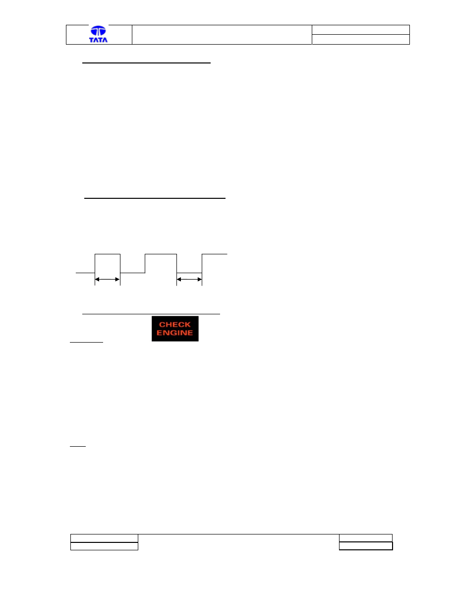
2.2 Operational mode : No fault indication
- CE lamp flashes as given below, if Diagnostics is enabled.
- CE lamp is OFF if Diagnostics is not enabled (See Fig 1)
Fig 1
2.3 Operational mode : Fault indication
- This lamp is ON to indicate fault, if Diagnostics is not enabled.
- Fault code is indicated on CE lamp in pattern given below,
Corresponding to fault logged by controller. Each code consists
of 2 non- zero decimal digits (digit of ten & of one) ,if Diagnostics
is enabled.
- If there are more codes, then CE lamp remains off for 3 sec.
between each flashing code.
- Table a side indicates list of faults & flash codes.
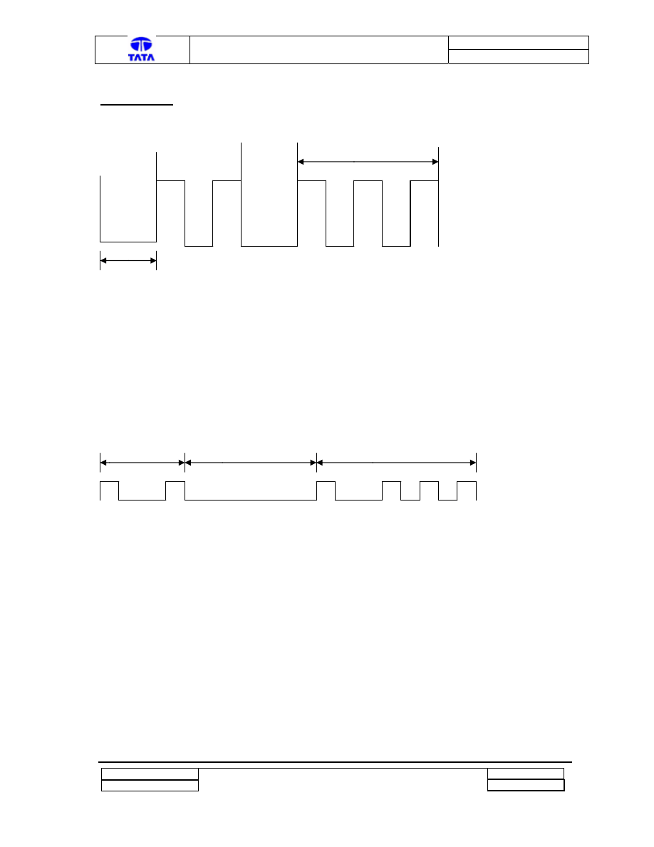
- Fig 2. below indicates fault code = 23.
Note : In case of any fault switch Off and On Ignition
and if fault persists investigate further
Lamp ON
Lamp OFF
0.3s
0.3s
Doc. No. : 2101 2273 16 62
TML – Diagnostic Manual A-ECU
Version : 1
Project :
Copyright © with TATA MOTORS
This document must not be used in any way, such as copying and redistributing to third parties, without our consent
Page 6 of 27
Author : TML
Dept : ERC-E&E
Flash Code 23.
Fig 2
2(tens)
3Seconds
2.4 Example of Two Simultaneous Faults
Two more faults can occur simultaneously. In that case each fault code is consecutively
displayed with a space of 3 seconds. Figure 3 shows a case where Fault code 11(Coolant sensor
open) and Fault code 13 Throttle pot open are present simultaneously. This sequence will repeat
till faults persist.
Fig 3
Fault code 11 3 Second Gap Fault Code 13
Lamp ON
Lamp OFF
3 (units)
Doc. No. : 2101 2273 16 62
TML – Diagnostic Manual A-ECU
Version : 1
Project :
Copyright © with TATA MOTORS
This document must not be used in any way, such as copying and redistributing to third parties, without our consent
Page 7 of 27
Author : TML
Dept : ERC-E&E
3.0 Trouble-shooting with Fault Codes.
This section explains trouble-shooting procedure to be followed in response to each of the fault
code. This procedure is intended as guide-line only which cover most of the situations . However
depending on peculiarity of a given situation, the service technician will have to use his
judgement and discretion.
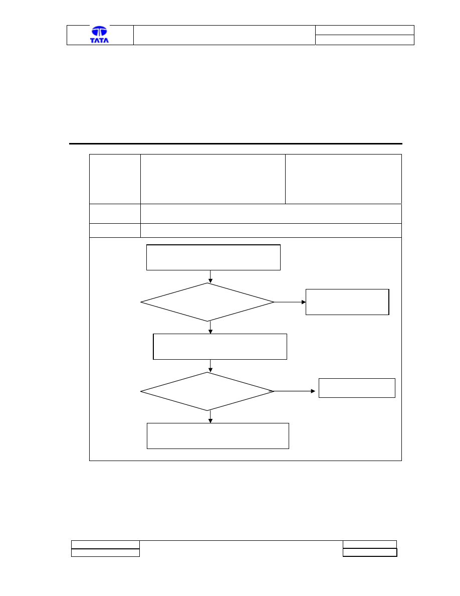
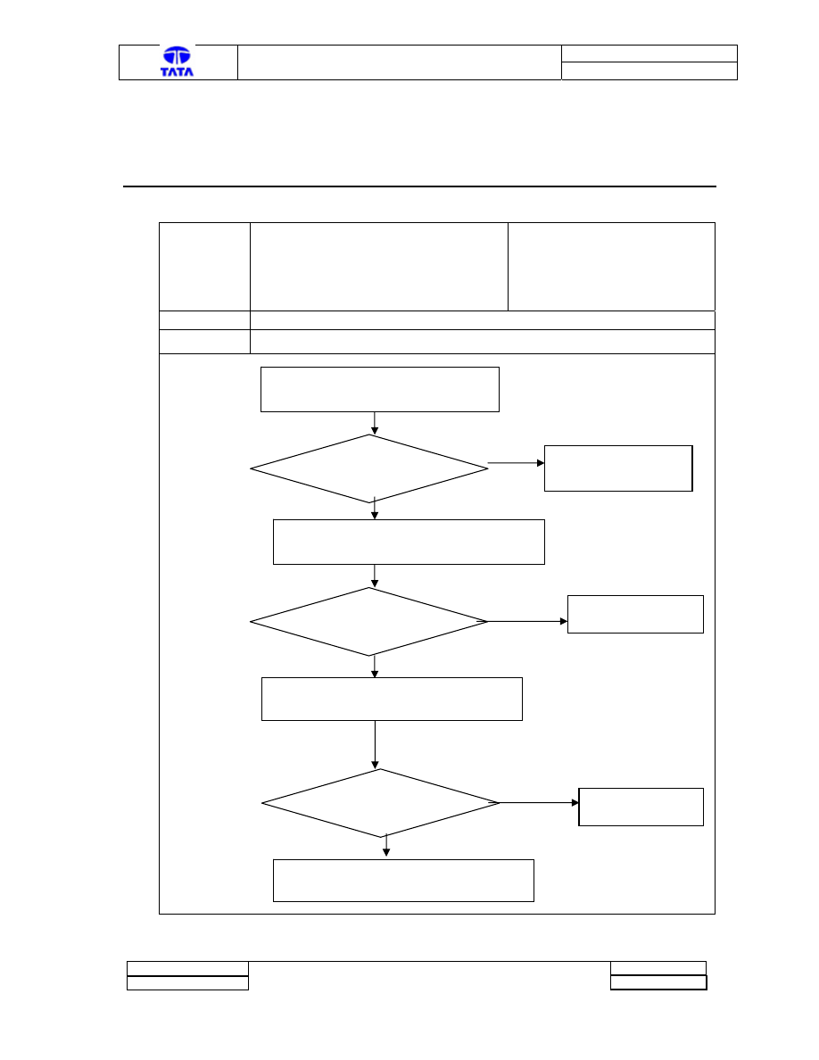
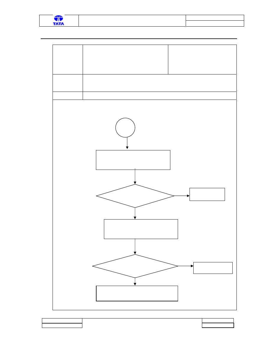
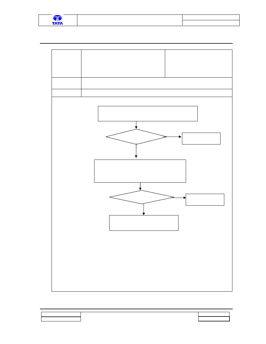
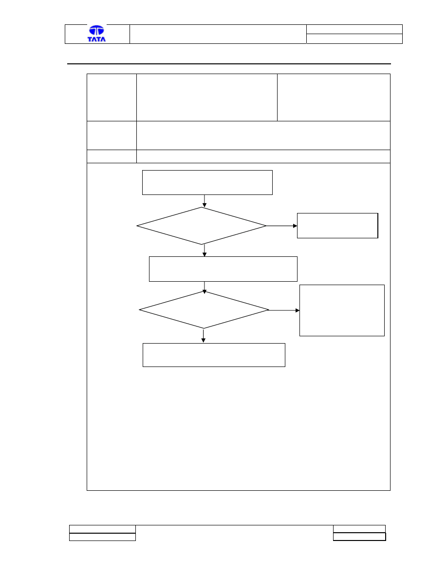
3.1 FAULT 11:
Fault code
11
Description
Coolant Temperature Sensor Open
Classification
Major
Detection
Value supplied by coolant temperature sensor is
Above allowable limit
Symptoms Emissions
(smoke).unsteady
idle
Checks:
Yes
No
Yes
Note 1: Resistance value varies as per coolant temperature. Generally this value should be few
kilo-ohms at temperatures above 40deg. At extreme low temperature this value reaches
100Kohm. Any value more than 100K and less than 500 ohms indicates resistance problem.
Connection
Problem
?
Check the sensor and AECU Connections
Rectify Connection
Problem
Measure Resistance between Sensor
Terminals
Resistance
Problem
?
Change the Sensor
Change AECU and re-confirm that the fault
does not persist.
Doc. No. : 2101 2273 16 62
TML – Diagnostic Manual A-ECU
Version : 1
Project :
Copyright © with TATA MOTORS
This document must not be used in any way, such as copying and redistributing to third parties, without our consent
Page 8 of 27
Author : TML
Dept : ERC-E&E
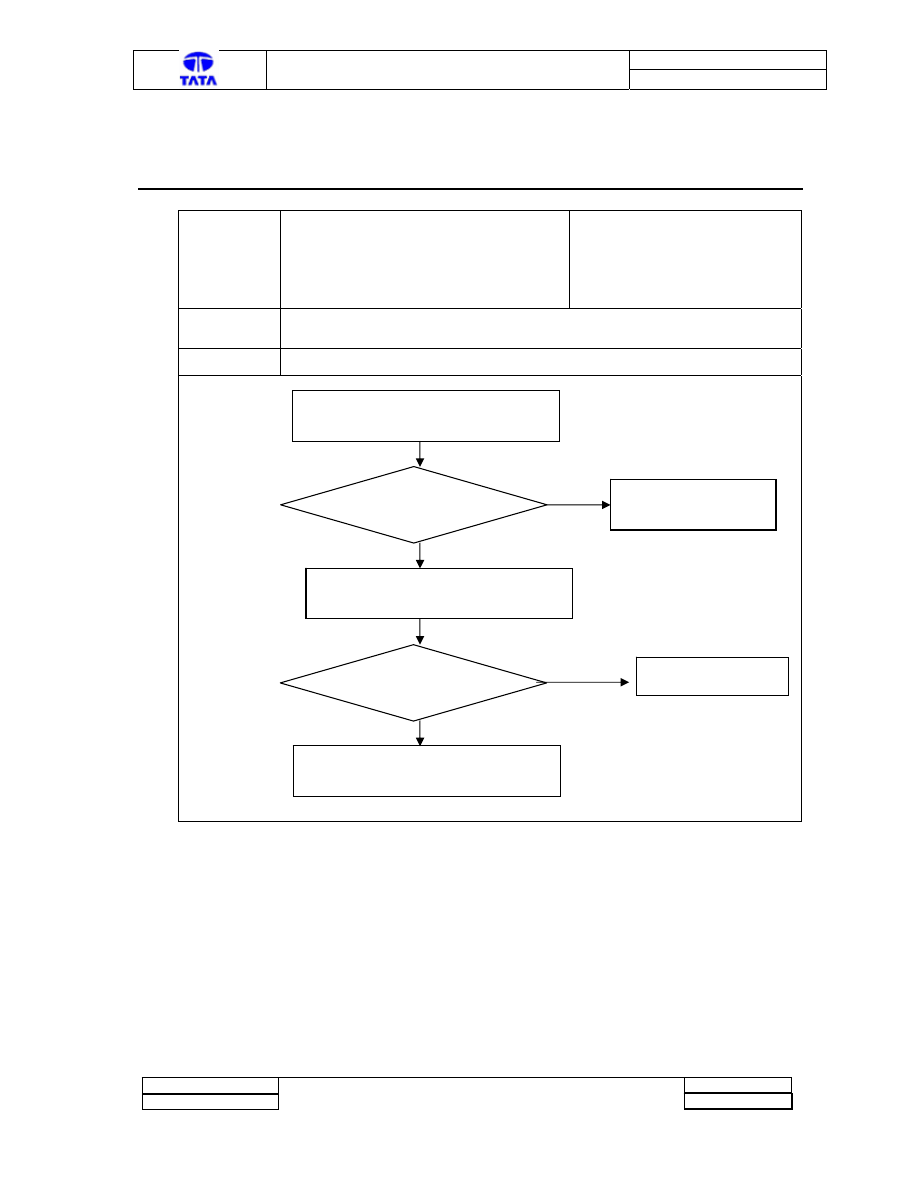
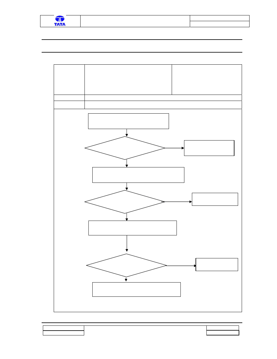
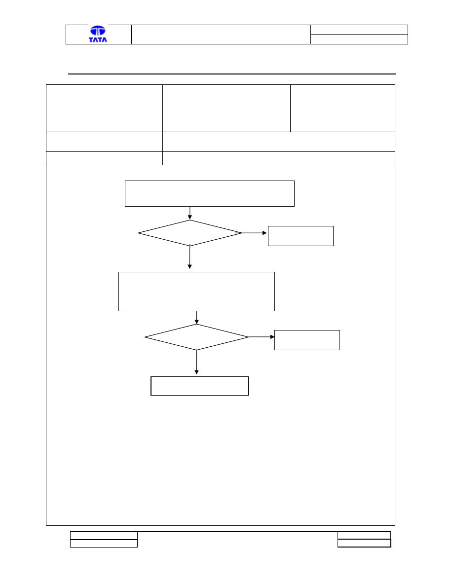
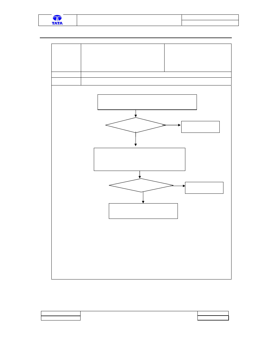
3.1 FAULT 12
Fault code
12
Description
Coolant Temperature Sensor Short
Classification
Major
Detection
Value supplied by coolant temperature sensor is
below allowable limit (See Note 1)
Symptoms Emissions
(smoke).unsteady
idle
Checks:
Yes
No
See Note 1
Yes
Note 1: Resistance value varies as per coolant temperature. Generally this value should be few kilo-ohms at temperatures above 40deg. At
extreme low temperature this value reaches 100Kohm. Any value more than 100K and less than 500 ohms indicates resistance problem
Connection
Problem
?
Check the sensor and AECU Connections
Rectify Connection
Problem
Measure Resistance between Sensor
Terminals
Resistance
Problem
?
Change the Sensor
Change AECU and re-confirm that the
fault does not persist
Doc. No. : 2101 2273 16 62
TML – Diagnostic Manual A-ECU
Version : 1
Project :
Copyright © with TATA MOTORS
This document must not be used in any way, such as copying and redistributing to third parties, without our consent
Page 9 of 27
Author : TML
Dept : ERC-E&E
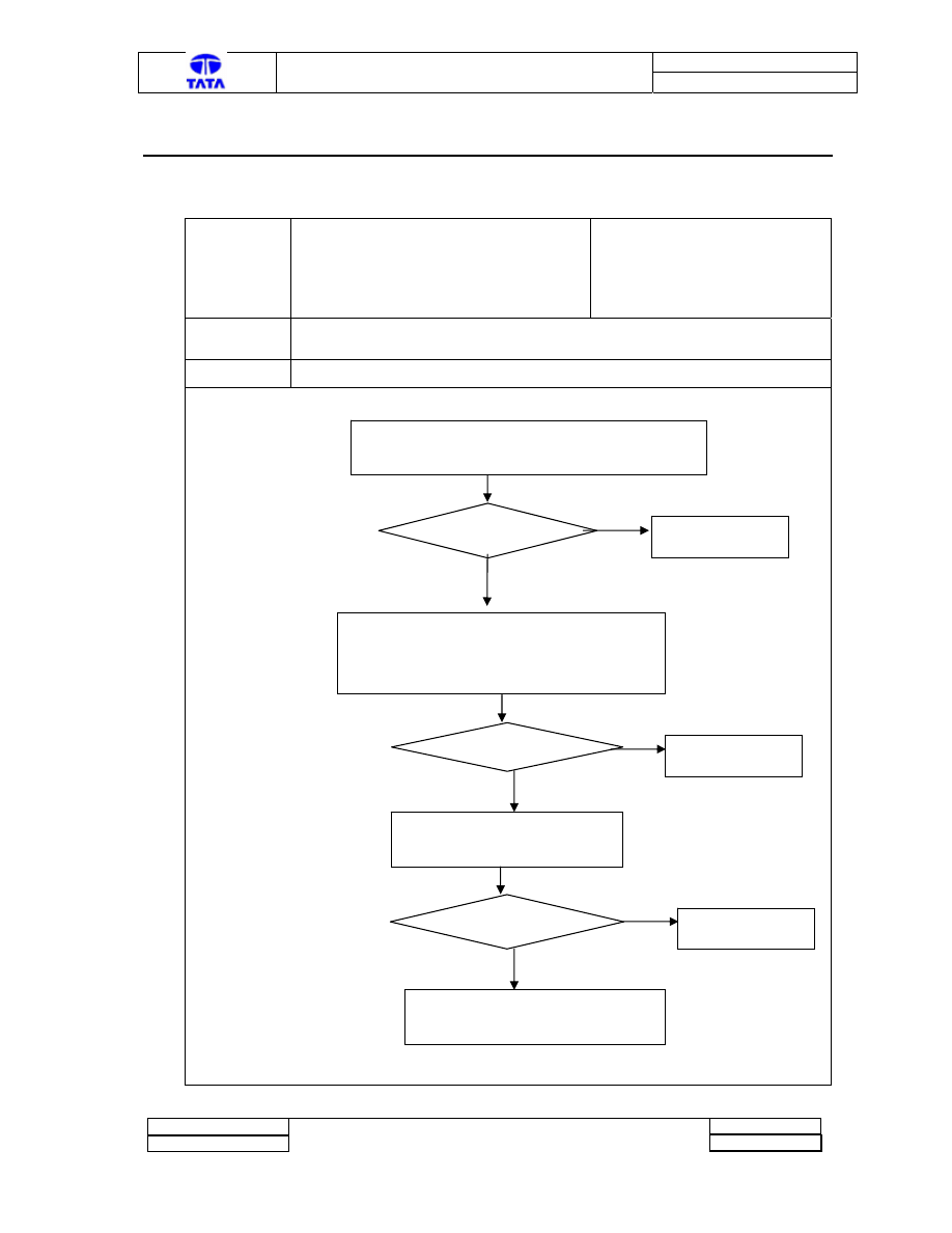
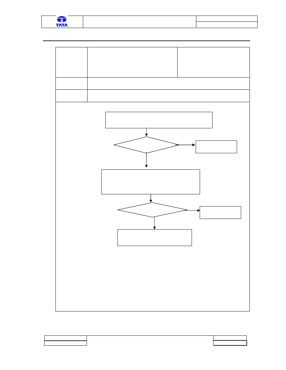
3.3 Fault Code 13
Fault code
13
Description
Throttle Lever Pot. Center/Supply point
open
Classification
Major
Detection
Throttle value read by AECU is below expected limit (See Note 1)
Symptoms
Emissions (smoke), Less pick-up during take-off with AC-on.
Checks:
See Note 1
Yes
No
Yes
No
Yes
No
Note 1: Resistance value depends on the throttle model used. Generally this value should be in the range of a few kilo-ohms
Resistance
Problem
?
Measure resistance between throttle
terminal 1 & 3 and 2 & 3
Change the throttle pot.
Measure voltage at AECU connector pins X1.13 to X1.12
Voltage should increase during acceleration (from 0.7 to 4.0
Volts)
Voltage
Problem?
Check the supply to
the sensor
Check AECU and Throttle Pot connections.
Connection
Problem?
Make necessary
repairs
Change AECU and re-confirm that
the fault does not persist
Doc. No. : 2101 2273 16 62
TML – Diagnostic Manual A-ECU
Version : 1
Project :
Copyright © with TATA MOTORS
This document must not be used in any way, such as copying and redistributing to third parties, without our consent
Page 10 of 27
Author : TML
Dept : ERC-E&E
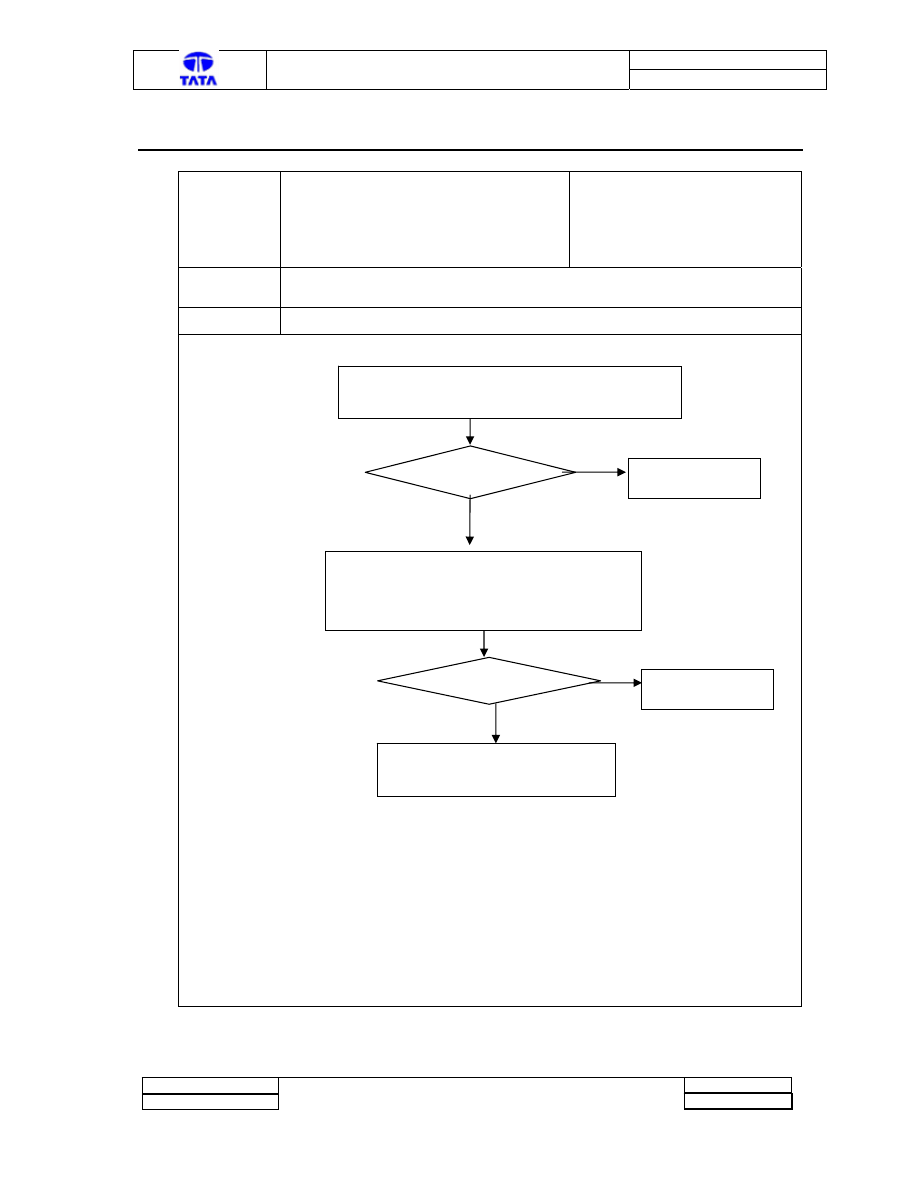
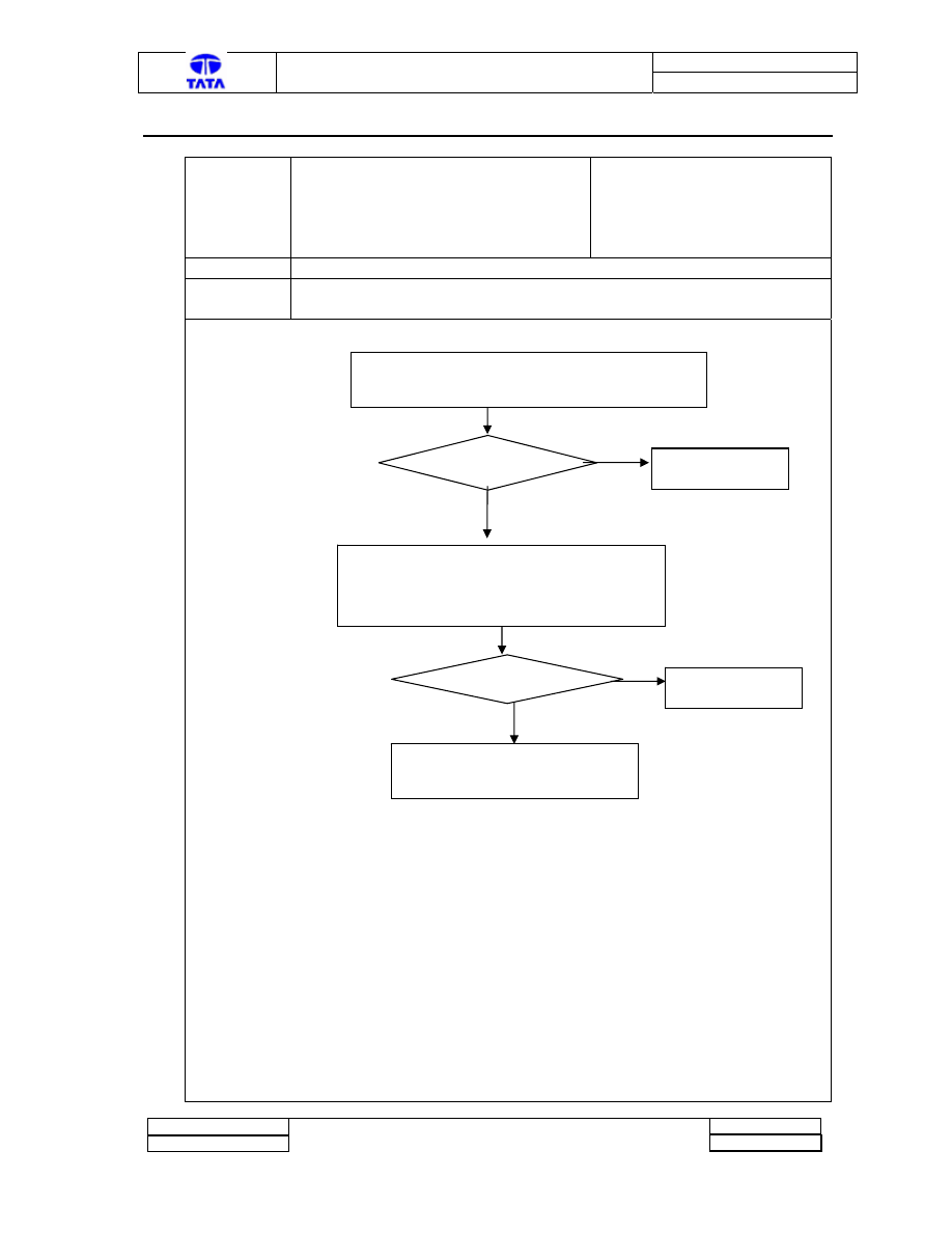
3.4 Fault Code 14
Fault code
14
Description
Throttle Lever Pot. Ground point open
Classification
Major
Detection
Throttle value read by AECU is above expected limit
Symptoms
Emissions (smoke), Less pick-up during take-off with AC-on.
Checks:
Yes
No
Yes
No
Yes
No
Note 1: Resistance value depends on the throttle model used. Generally this value should be in the range of a few kilo-ohms
Resistance
Problem
?
Measure resistance between throttle
terminal 1 & 3 and 2 & 3
Change the throttle pot.
Measure voltage at AECU connector pins X1.13 to X1.12
Voltage should increase during acceleration (from 0.7 to 3.8
Volts)
Voltage
Problem?
Check the supply to
the sensor
Check AECU and Throttle Pot connections.
Connection
Problem?
Make necessary
repairs
Change AECU
Doc. No. : 2101 2273 16 62
TML – Diagnostic Manual A-ECU
Version : 1
Project :
Copyright © with TATA MOTORS
This document must not be used in any way, such as copying and redistributing to third parties, without our consent
Page 11 of 27
Author : TML
Dept : ERC-E&E
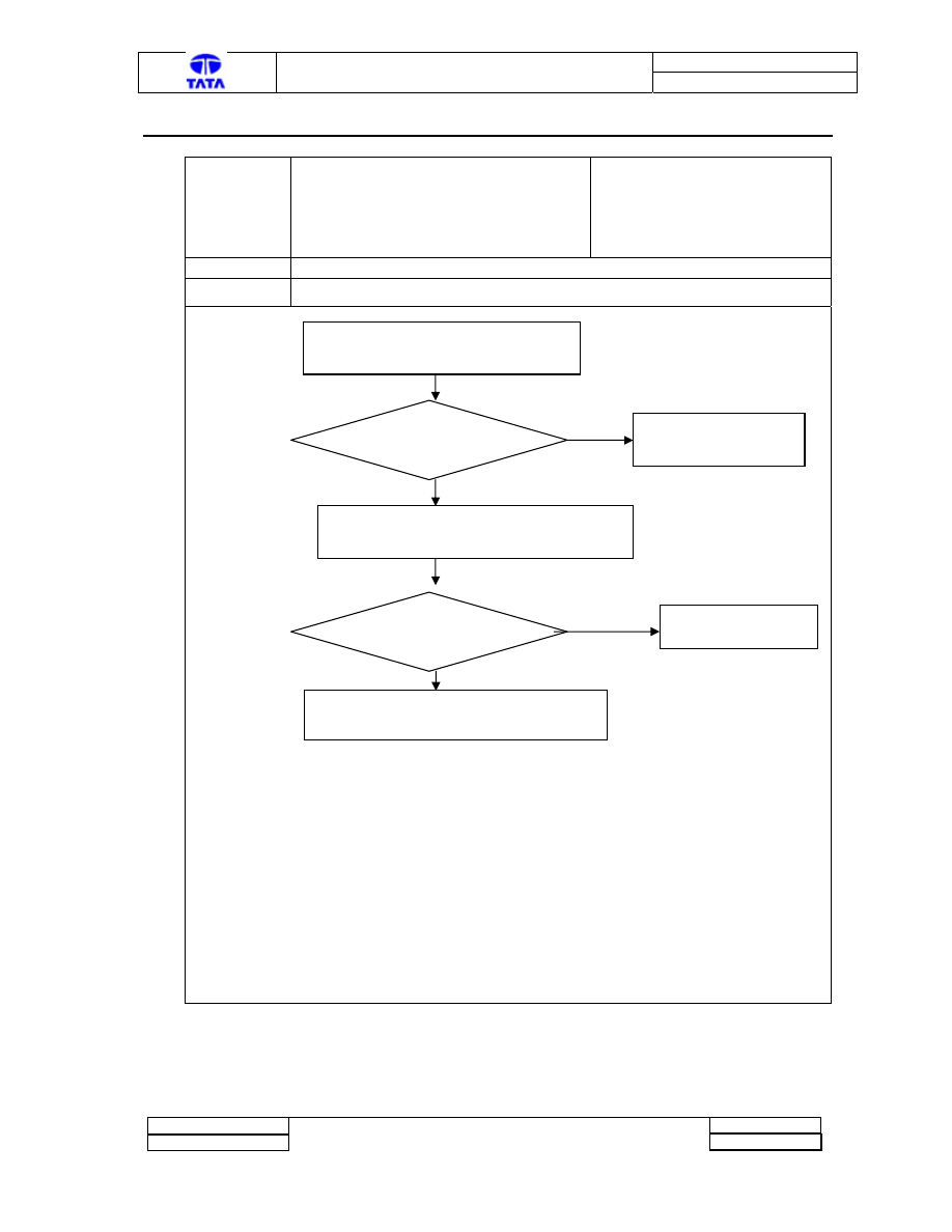
3.5 Fault Code 15
Fault code
15
Description
Loss of RPM signal
Classification
Major
Detection
RPM signal not sensed by AECU after one minute from cranking
Symptoms
Emissions (smoke), Less pick-up during take-off with AC-on.
Checks:
Yes
No
Yes
No
Connection
Problem?
Check connections with alternator “W”
terminal
Make necessary repairs.
Measure the pulse waveform at AECU connector terminal
X1.7 (connector with black housing)
Alternator signal
problem
?
Change the Alternator
Change AECU
Doc. No. : 2101 2273 16 62
TML – Diagnostic Manual A-ECU
Version : 1
Project :
Copyright © with TATA MOTORS
This document must not be used in any way, such as copying and redistributing to third parties, without our consent
Page 12 of 27
Author : TML
Dept : ERC-E&E
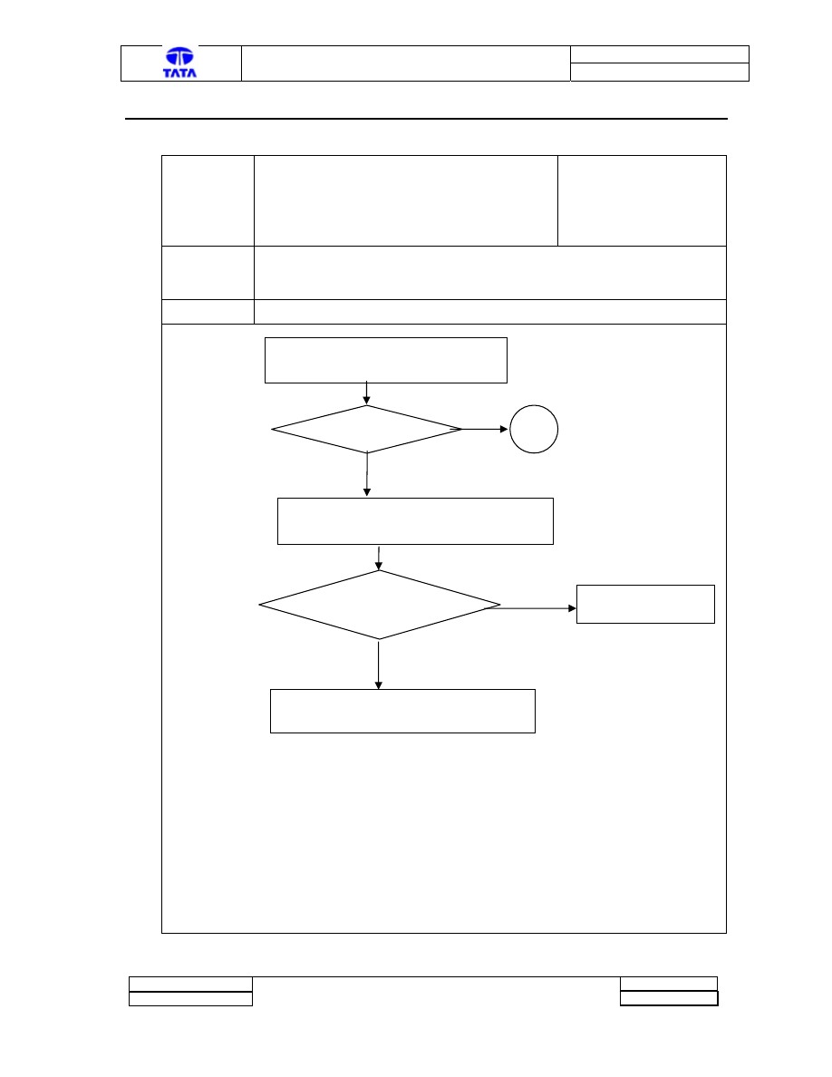
3.6 Fault Code 16
Fault code
16
Description
Glow-plug Interface Unit/Glow-plug faulty or
Glow-Plug On command or feedback wire
open
Classification
Major
Detection
1. Engine does not start after switching on glow-plugs.
2.AECU does not receive feedback for relay on after issuing “GP on
command”
Symptoms
Emissions (smoke), Starting trouble
Checks:
Yes
No
Yes
No
Voltage Problem?
Check voltage at AECU connector pin
X2.2 with ignition on. (<8Volt)
Measure Voltage appearing across Glow-plugs at ignition on
Glow-plug voltage =
Battery Voltage?
Change the Glow-plug if
engine is not cranking
This is due to connection problem.
Check connections from GPIU to glow-plug
A
Doc. No. : 2101 2273 16 62
TML – Diagnostic Manual A-ECU
Version : 1
Project :
Copyright © with TATA MOTORS
This document must not be used in any way, such as copying and redistributing to third parties, without our consent
Page 13 of 27
Author : TML
Dept : ERC-E&E
3.6 Fault code 16 (contd..)
Fault code
16
(Contd..)
Description
Glow-plug Interface Unit/Glow-plug
faulty or GP On command or feedback
wire open
Classification
Major
Detection
1.0 Engine does not start after switching on glow-plugs.
2.0AECU does not receive feedback for relay on after issuing “GP on
command”
Symptoms
Emissions (smoke), Starting trouble
Checks: (Contd..)
Feedback Voltage from GPIU Not Ok
Yes
No
No
Yes
A
Voltage Ok?
Measure Voltage between pin 4
and Pin 2 of GPIU at ignition on
(It should be <0.8 Volts)
Change GPIU
Voltage Ok?
Measure Voltage At AECU
connector x2.13 at ignition on (It
should be <0.8 Volts)
Change AECU
This is a connection problem Check
Aecu to GPIU connection and rectify
Doc. No. : 2101 2273 16 62
TML – Diagnostic Manual A-ECU
Version : 1
Project :
Copyright © with TATA MOTORS
This document must not be used in any way, such as copying and redistributing to third parties, without our consent
Page 14 of 27
Author : TML
Dept : ERC-E&E
3.7 Fault Code 17
Fault code
17
Description
Glow-plug Relay Stuck
Classification
Major
Detection
Detected if “Glow-Plug relay on “ feedback persists after removal
of command
Symptoms
Emission (Smoke), Battery Charge Balance Problems
Checks:
Yes
No
No
Yes
Check Voltage GP command signal from AECU (x2.13)
when the fault is flashing . Expected Voltage > 8Volt
Voltage Problem?
Measure voltage at AECU Gp-feedback input
(Expected Voltage <0.8 volts)
Change AECU
Voltage Problem?
Change GPIU
Change AECU
Doc. No. : 2101 2273 16 62
TML – Diagnostic Manual A-ECU
Version : 1
Project :
Copyright © with TATA MOTORS
This document must not be used in any way, such as copying and redistributing to third parties, without our consent
Page 15 of 27
Author : TML
Dept : ERC-E&E
3.8 Fault Code 18
Fault code
18
Description
Glow-plug Relay Command Line
Shorted to Supply
Classification
Major
Detection
Detected if Glow-Plug Command Line is sensed as “shorted to supply” by
AECU
Symptoms
Emission(smoke), Starting Problems
Checks:
No
Yes
No
Yes
No
Yes
Check Voltage GP command signal from AECU (x2.13)
at ignition on. Expected Voltage <0. 8Volt
Voltage Problem?
Switch off ignition and Unplug GPIU
Carry out cold check of the harness connection at
AECU pin x2.13 to see if short to supply still exists
Change AECU
Still short to supply?
Unplug AECU x2 connector and
re-check if short to supply exists
Change GPIU
Still short to supply?
This is a Harness connection problem.
Carry out necessary repairs
Change AECU

Doc. No. : 2101 2273 16 62
TML – Diagnostic Manual A-ECU
Version : 1
Project :
Copyright © with TATA MOTORS
This document must not be used in any way, such as copying and redistributing to third parties, without our consent
Page 16 of 27
Author : TML
Dept : ERC-E&E
3.9 Fault Code 21
Fault code
21
Description
Glow-plug Lamp (Pre-heat) shorted to
supply
Classification
Minor
Detection
Detected if Glow-plug Lamp (Pre-heat)output is sensed as “shorted to
supply” by AECU
Symptoms
Pre-heat lamp does not glow at “ignition on”
Checks:
Yes
No
No
Yes
Check pre-heat lamp for possible short-circuit
Lamp Short?
Switch off ignition and Unplug AECU connector
Carry out cold check of the harness connection at
AECU pin x2.11 to see if short to supply still exists
Change Lamp
Still short to supply?
This is a Harness connection problem.
Carry out necessary repairs
Change AECU
Doc. No. : 2101 2273 16 62
TML – Diagnostic Manual A-ECU
Version : 1
Project :
Copyright © with TATA MOTORS
This document must not be used in any way, such as copying and redistributing to third parties, without our consent
Page 17 of 27
Author : TML
Dept : ERC-E&E
3.10 Fault code 22
Fault code
22
Description
Glow-plug Lamp (Pre-heat) Open/wire
open
Classification
Minor
Detection
Detected if Gp Lamp (Pre-heat)output is sensed as “open circuit” by
AECU
Symptoms
Pre-heat lamp does not glow at “ignition on”
Checks:
Yes
No
Yes
No.
Check pre-heat lamp for possible open circuit
Lamp Open?
Check harness connections from AECU pin x2.11
to the lamp for a possible open circuit
Change Lamp
Connections are ok?
This is a Harness connection problem.
Carry out necessary repairs
Change AECU
Doc. No. : 2101 2273 16 62
TML – Diagnostic Manual A-ECU
Version : 1
Project :
Copyright © with TATA MOTORS
This document must not be used in any way, such as copying and redistributing to third parties, without our consent
Page 18 of 27
Author : TML
Dept : ERC-E&E
3.11 Fault Code 23
Fault code
23
Description
AC Relay coil shorted to Supply
Classification
Minor
Detection
Detected if AC relay coil output is sensed as “shorted to supply” by
AECU
Symptoms Air-conditioning
cannot
switch-on.
Checks:
Yes
No
No
Yes
Check AC relay coil for possible short circuit.
Relay coil Short?
Switch off ignition and Unplug AECU connector
Carry out cold check of the harness connection at
AECU pin x2.12 to see if short to supply still exists
Change AC relay
Still short to supply?
This is a Harness connection problem.
Carry out necessary repairs
Change AECU
Doc. No. : 2101 2273 16 62
TML – Diagnostic Manual A-ECU
Version : 1
Project :
Copyright © with TATA MOTORS
This document must not be used in any way, such as copying and redistributing to third parties, without our consent
Page 19 of 27
Author : TML
Dept : ERC-E&E
3.12 FAULT CODE 24
Fault code
24
Description
AC Relay coil Open/wire open
Classification
Minor
Detection
Detected if AC relay coil output is sensed as “open circuit” by AECU
Symptoms
Air-conditioning cannot be switched on
Checks:
Yes
No
Yes
No.
Check AC relay coil for possible open circuit
Relay Open?
Check harness connections from AECU pin x2.12
to the AC relay coil for a possible open circuit
Change Relay
Connections are ok?
This is a Harness connection problem.
Carry out necessary repairs
Change AECU
Doc. No. : 2101 2273 16 62
TML – Diagnostic Manual A-ECU
Version : 1
Project :
Copyright © with TATA MOTORS
This document must not be used in any way, such as copying and redistributing to third parties, without our consent
Page 20 of 27
Author : TML
Dept : ERC-E&E
3.13 FAULT CODE 27
Fault code
27
Description
“Fan-Series” Relay coil shorted to
Supply
Classification
Major
Detection
Detected if “Fan-Series” relay output is sensed as “shorted to supply” by
AECU
Symptoms
Low-speed Operation of Fans not possible. NVH may increase
accompanied with possible charge balance problems.
Checks:
Yes
No
No
Yes
Check “Fan-Series” relay for possible short circuit.
Relay coil Short?
Switch off ignition and Unplug AECU connector
Carry out cold check of the harness connection at
AECU pin x1.15 to see if short to supply still exists
Change the relay
Still short to supply?
This is a Harness connection problem.
Carry out necessary repairs
Change AECU
Doc. No. : 2101 2273 16 62
TML – Diagnostic Manual A-ECU
Version : 1
Project :
Copyright © with TATA MOTORS
This document must not be used in any way, such as copying and redistributing to third parties, without our consent
Page 21 of 27
Author : TML
Dept : ERC-E&E
3.14 Fault Code 28
Fault code
28
Description
“Fan-series Relay” coil Open/wire open
Classification
Major
Detection
Detected if fan-series relay coil is sensed as “open circuit” by AECU
Symptoms
Low-speed Operation of Fans not possible. NVH may increase
accompanied with possible charge balance problems.
Checks:
Yes
No
Yes
No.
Check “Fan-Series” relay coil for possible open circuit
Relay Open?
Check harness connections from AECU pin x1.15
to the AC relay coil for a possible open circuit
Change Relay
Connections are ok?
This is a Harness connection problem.
Carry out necessary repairs
Change AECU
Doc. No. : 2101 2273 16 62
TML – Diagnostic Manual A-ECU
Version : 1
Project :
Copyright © with TATA MOTORS
This document must not be used in any way, such as copying and redistributing to third parties, without our consent
Page 22 of 27
Author : TML
Dept : ERC-E&E
3.15 Fault code 29
Fault code
29
Description
Throttle Lever Pot. Wrong connections
Classification
Major
Detection
Throttle value read by AECU at ignition on is more than 2.5 Volt
(This also occurs if the throttle is pressed during cranking See Note 1
below)
Symptoms
Emissions (smoke), Less pick-up during take-off with AC-on.
Checks:
Yes
No
Yes
No
Note 1: The customer is not supposed to press throttle before and during cranking the engine. Otherwise
fault code number 29 will be issued. AECU based system uses mechanical fuel-injection system. Hence
fuel will be injected during cranking if throttle is pressed at the time of cranking causing smoke. HENCE
PRESSING THROTTLE DURING CRANKING IS NOT RECOMMENDED.
Resistance
Problem
?
Measure resistance between throttle
terminal 1 & 3 and 2 & 3
Change the throttle pot.
Measure voltage at AECU connector pins X1.13 to X1.12 at
the time of ignition on. Voltage should be less than 0.8 volt
Voltage
Problem?
This a connection
problem. Most probably
connections to throttle
supply and ground are
reversed. Make necessary
repairs.
Change AECU
Doc. No. : 2101 2273 16 62
TML – Diagnostic Manual A-ECU
Version : 1
Project :
Copyright © with TATA MOTORS
This document must not be used in any way, such as copying and redistributing to third parties, without our consent
Page 23 of 27
Author : TML
Dept : ERC-E&E
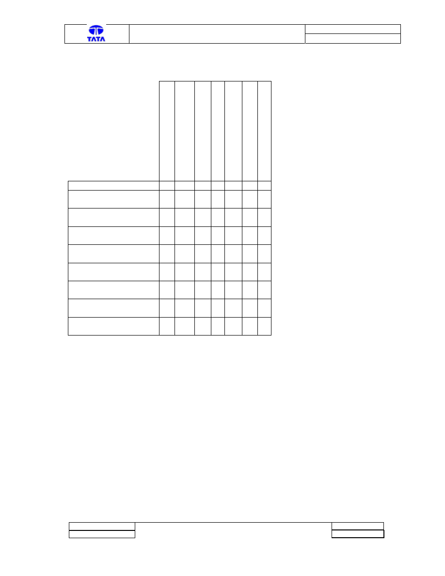
3.16 Table of Symptoms
Em
is
si
o
n
s
Slow To
Start/St
a
rting
Tro
uble
No
is
e
Air-c
o
n
d
ition
in
g off
Le
s
s
-P
ick
u
p
d
u
ring AC-on
B
a
tt
e
ry
Char
g
e
B
a
lanc
e
P
roblem
P
re
-H
eat Lamp Off
Fault
Coolant Sensor short/Open
x
Throttle Lever Potentiometer
Connections open/wrong
x
x
Loss of RPM signal
x
x
Glow-Plug/GPIU related
Problem
x
x
Glow-Plug Relay stuck
x
x
Glow-Plug Lamp short/Open
x
AC Relay coil short/open
x
Fan Series Relay open/short
x
x
Doc. No. : 2101 2273 16 62
TML – Diagnostic Manual A-ECU
Version : 1
Project :
Copyright © with TATA MOTORS
This document must not be used in any way, such as copying and redistributing to third parties, without our consent
Page 24 of 27
Author : TML
Dept : ERC-E&E
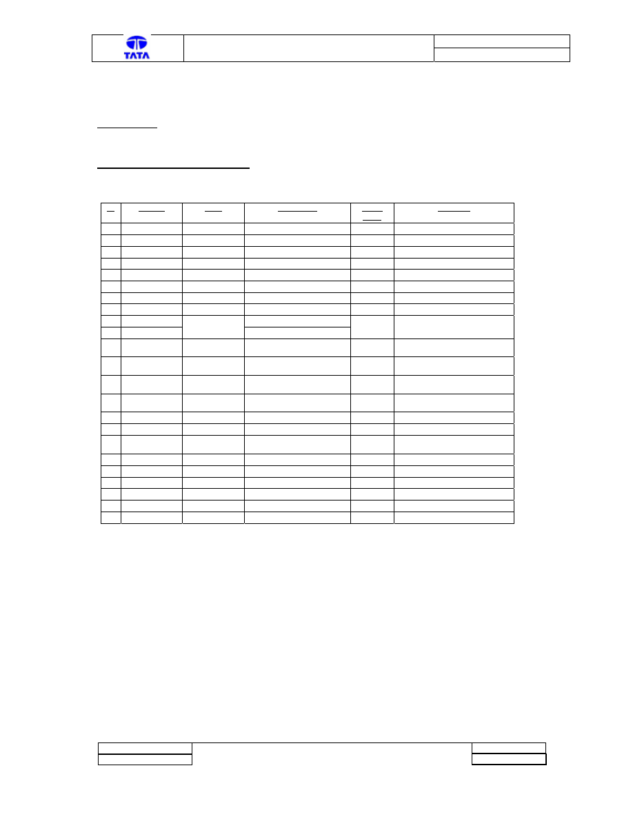
Appendix A
A-ECU Pin Out Configuration :
Sr Ter.
No Type Description Active
Level
Condition
1
X1.1, X 1.10
Supply
+ Supply for Controller
VCC
Permanent
2
X2.9, X2.18
Ground
- Supply for Controller
GND
Permanent
3 X2.1
Input
Crank
High
Engine
Cranked
4
X2.4
Input
Enable Diagnostics
Low
Enables Diag. Thro’ CE lamp
5
X2.7
Input
Air Conditioner ON
High
I/p from vehicle’s electrical ckt.
6
X2.2
Input
Glow Plug On Feedback
VCC
Glow Plug are ON
7
X2.5
Input
A/C present/absent
Low
Ac system absent
8
X1.4
Analogue I/p
Voltage=> GP Current
0-5Vdc
Voltage varies with Gpcurrent
9
X1.5
Coolant Temp. Sensor pin1
10 X2.9
Analogue I/p
Coolant Temp. Sensor pin2
11
X1.11
Output
Throttle position sensor
supply
5 V dc
Permanent
12
X1.12
Output
Throttle position sensor
Gnd
Gnd Permanent
13
X1.13
Analogue I/p
Throttle position sensor
Output
0-5 V dc
Voltage varies with throttle
position
14
X1.7
Input Pulses
Engine Speed signal from
alternator
High
Pulse
Pulses as per engine speed
15 X1.16
Output
Fans
In
Parallel
Low
Logical
condition
16 X1.15
Output
Fans
In
Series
Low
Logical
condition
17
X1.17
Output
EGR Solenoid
Low
Logical condition (A ECU
Temp. >-18
°C)
18 X1.18
Output
FICD
Solenoid
Low
Logical
condition
19
X2.11
Output
Pre-Heat Lamp
Low
Logical condition
20
X2.13
Output
Glow Plug On Command
Low
Logical condition
21
X2.10
Output
Check Engine Lamp
Low
Logical condition
22
X2.12
Output
Air Condition ON
Low
Logical condition
23 X2:17
Output
Cold
advance
Low
Logical
condition
Doc. No. : 2101 2273 16 62
TML – Diagnostic Manual A-ECU
Version : 1
Project :
Copyright © with TATA MOTORS
This document must not be used in any way, such as copying and redistributing to third parties, without our consent
Page 25 of 27
Author : TML
Dept : ERC-E&E
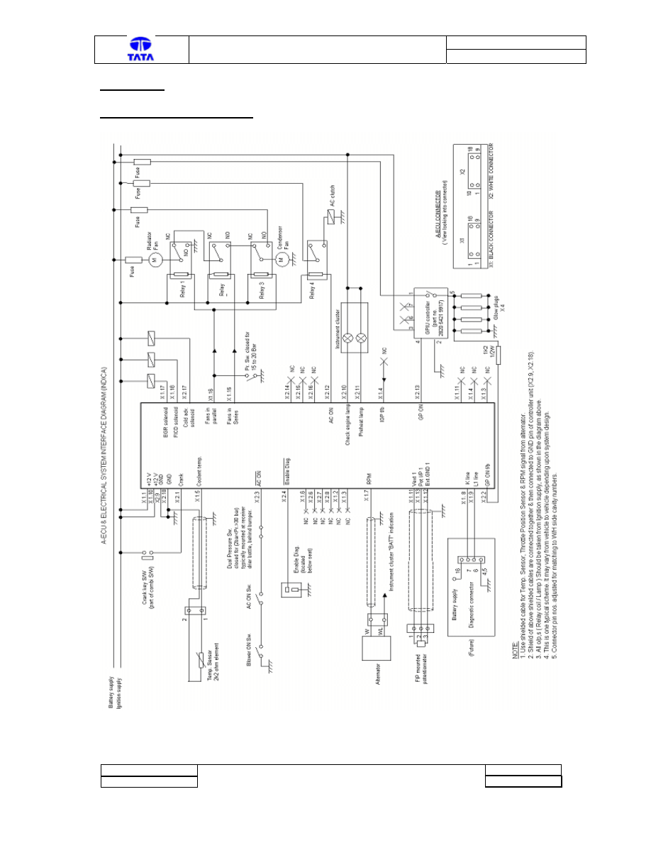
Appendix B:
Circuit schematic for A-ECU:
Doc. No. : 2101 2273 16 62
TML – Diagnostic Manual A-ECU
Version : 1
Project :
Copyright © with TATA MOTORS
This document must not be used in any way, such as copying and redistributing to third parties, without our consent
Page 26 of 27
Author : TML
Dept : ERC-E&E
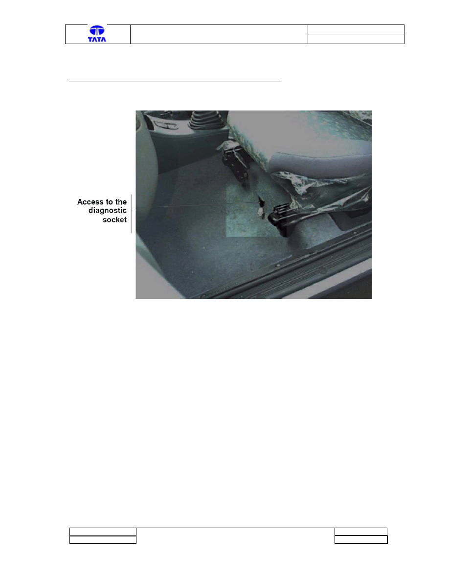
Appendix C
Location of Blink Code enable (2-Pole) Diagnostic Connector:
Doc. No. : 2101 2273 16 62
TML – Diagnostic Manual A-ECU
Version : 1
Project :
Copyright © with TATA MOTORS
This document must not be used in any way, such as copying and redistributing to third parties, without our consent
Page 27 of 27
Author : TML
Dept : ERC-E&E
END OF DOCUMENT
Wyszukiwarka
Podobne podstrony:
C5 (X7) D6AY01KAP0 9 23 07 2013 Pomoc w diagnostyce Manualna (mechaniczna) skrzynia biegów i sp
BCM Diagnosis Manual 0V2
CARPROG Opel ECU programmer user manual
Digital ECU Tuner III Manual
original c68 retail diy auto diagnostic tool manual
diagnostyka i techniki w terapii manualnej
zajęcia 1 techniki i diagnozy terapii manualnej-druk, terapia manualna
ECU Diagnostics
Techniki diagnozy i terapii manualnej
Diagnostyka usterek sprzęgła, - !!! SKRZYNIE BIIEGÓW AUTOMATYCZNE I MANUALNE !!! -
CARPROG Opel ECU programmer user manual
Digital ECU Tuner III Manual
original c68 retail diy auto diagnostic tool manual
The Merck Manual Objawy kliniczne Praktyczny przewodnik diagnost Kaminski Bogdan Klin Zuzanna Ksiad
Digital ECU Tuner II Manual(4)
Digital ECU Tuner III Manual
Digital ECU Tuner III FIT Manual
więcej podobnych podstron