Doc. No.:
2101 2313 00 98
TML – Diagnostic Manual BCM
Version:
0.2
Diagnostic Manual for BCM
PURPOSE: This document details the Diagnostic Procedure for BCM used in Indigo XL and
Xenon vehicles.
NOTE: This document is subject to change based on the BCM Hardware & software changes.
Project: Body Control Module
Copyright © with TATA MOTORS
This document must not be used in any way, such as copying and redistributing to third parties, without our consent
Dept: ERC - E & E
Page 1 of 27
Author: Anil Joshi
Doc. No.:
2101 2313 00 98
TML – Diagnostic Manual BCM
Version :
0.2
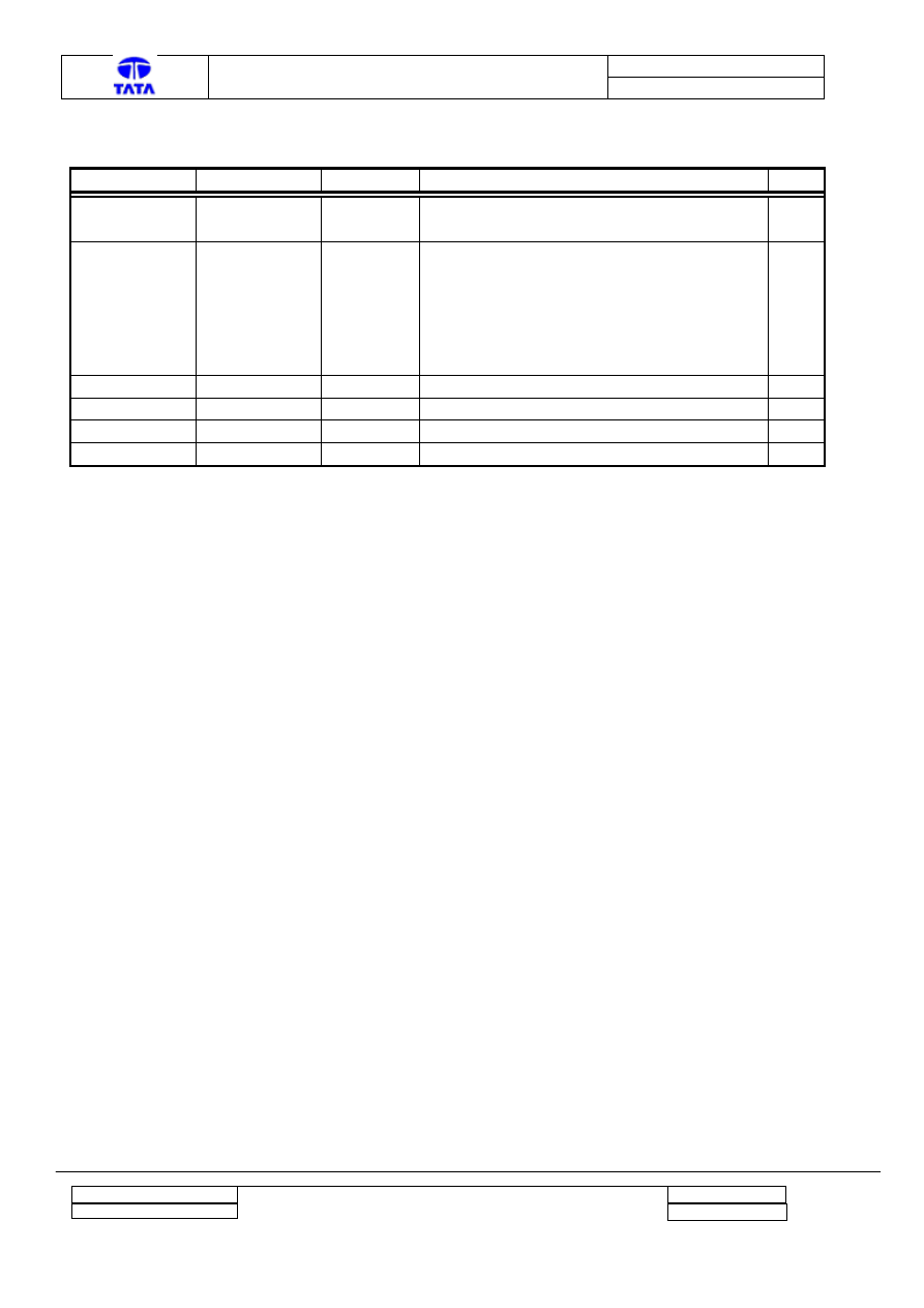
Revision History
Prepared by
Approved by
Date
Reason For Changes
Ver
Anil Joshi
Sanjeev
Maralihalli
04-July-07
First version
0.1
Anil Joshi
Sanjeev
Maralihalli
12-Sep-07
• The case of Engine not starting due to
Inertia active is added.
• Snapshots of the OBD Connector and
BCM locations are added.
• The Break point information for BCM is
added.
0.2
Project : Body Control Module
Copyright © with TATA MOTORS
This document must not be used in any way, such as copying and redistributing to third parties, without our consent
Dept : ERC - E & E
Page 2 of 27
Author : Anil Joshi

Doc. No.:
2101 2313 00 98
TML – Diagnostic Manual BCM
Version :
0.2
Index
Project : Body Control Module
Copyright © with TATA MOTORS
This document must not be used in any way, such as copying and redistributing to third parties, without our consent
Dept : ERC - E & E
Page 3 of 27
Author : Anil Joshi
Doc. No.:
2101 2313 00 98
TML – Diagnostic Manual BCM
Version :
0.2
1 Introduction
This document gives information about the Diagnosis Tool called as Tester, for the Body Control
Module (BCM). It provides the capability of accessing information and functions of the control
unit without disconnecting the cable harness. The diagnosis, thus allows all input signals applied to
the ECU to be read, monitor, force input/output and read-out ECU-internal information, such as
the contents of the fault-memory.
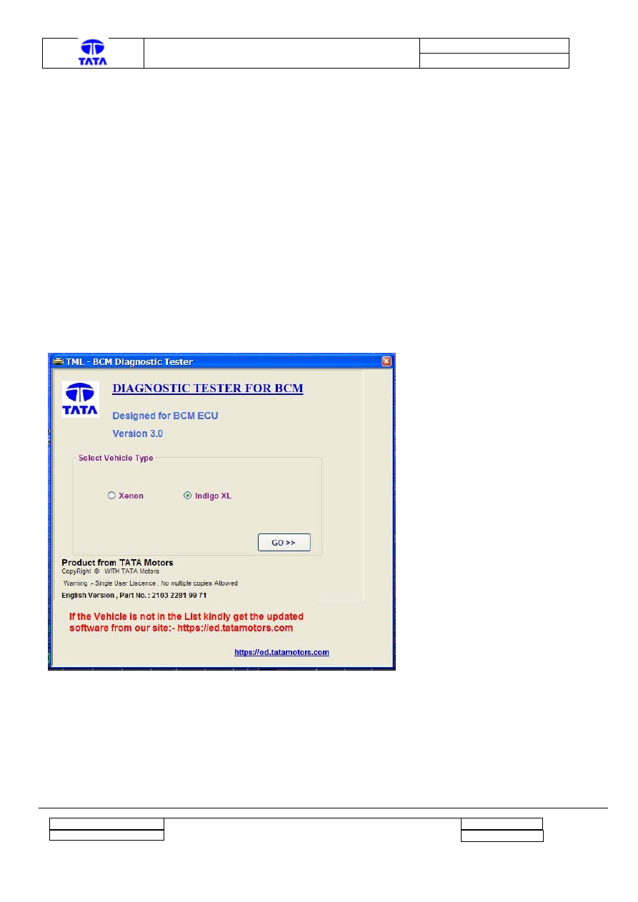
2 Features of the Tool
2.1
BCM type selection
The Diagnosis Tool is common for the Indigo XL and Xenon vehicle. The screen is provided for
selecting the Vehicle. With this, the BCM functions, which are not applicable for the particular
Vehicle, are hidden. This helps in maintaining the same tool for both BCMs.
The screen shot is as shown below.
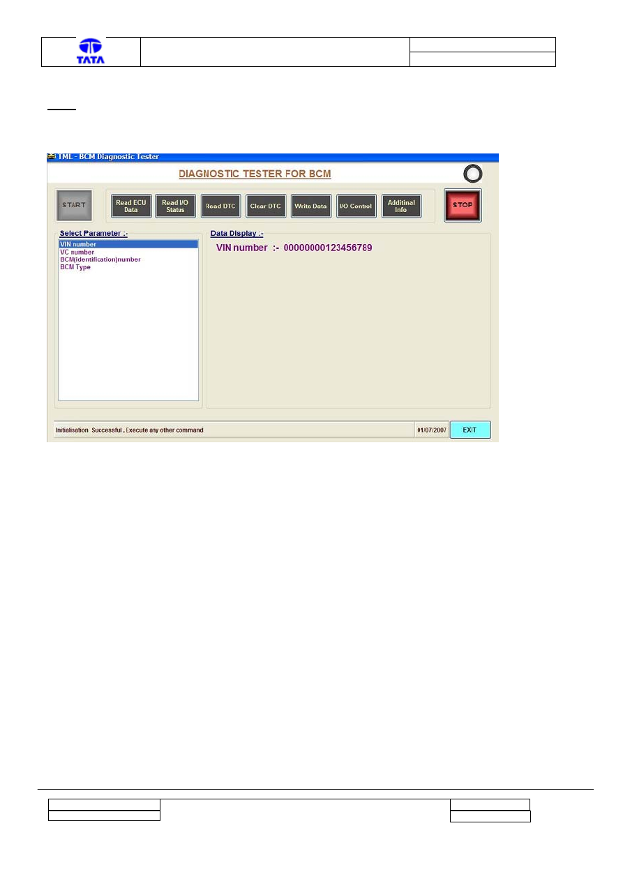
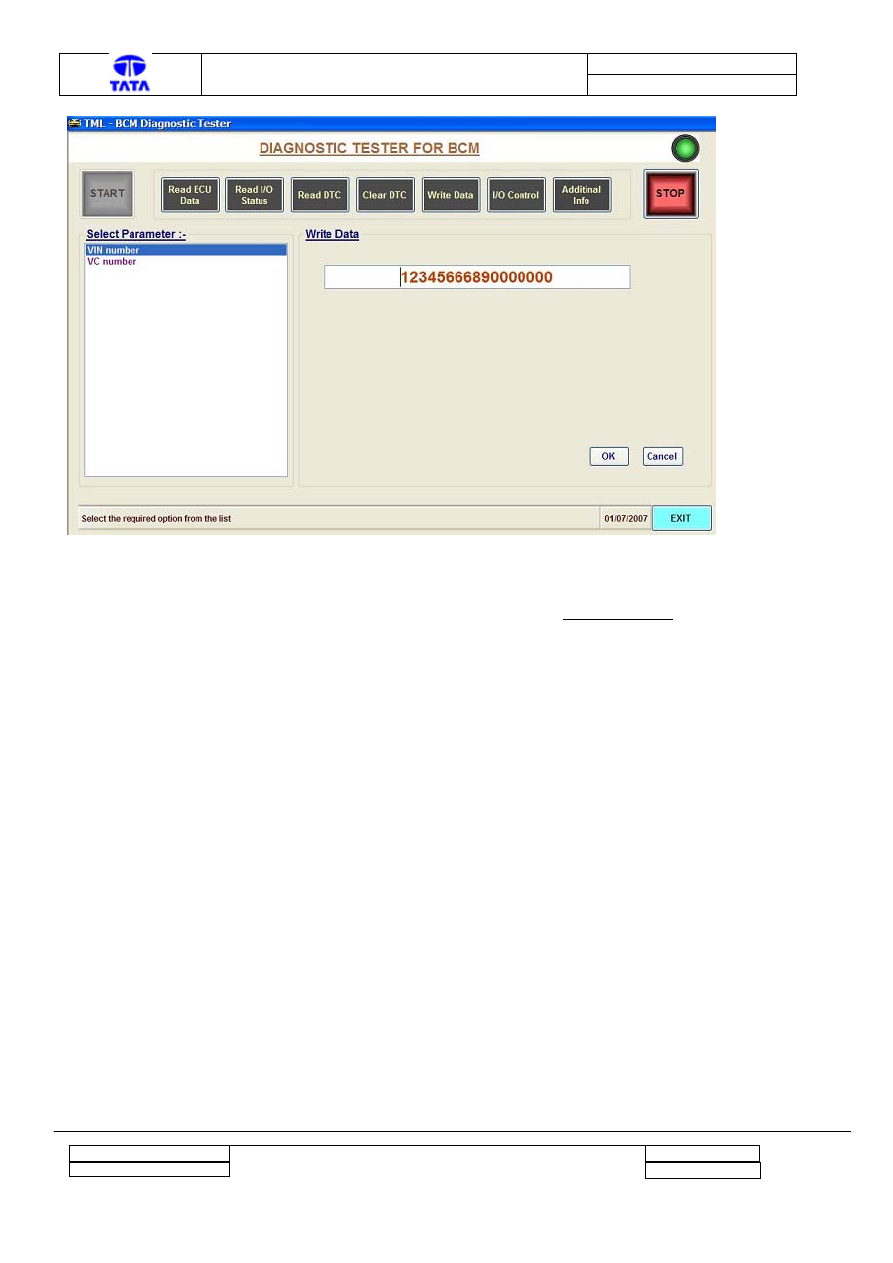
2.2
Read / Write BCM and Vehicle Identification
It is possible to Write or Read the following data into / from BCM respectively.
a. VIN (Read /Write)
b. VC (Read /Write)
c. BCM Identification (Read Only)
d. BCM type (Read Only)
Project : Body Control Module
Copyright © with TATA MOTORS
This document must not be used in any way, such as copying and redistributing to third parties, without our consent
Dept : ERC - E & E
Page 4 of 27
Author : Anil Joshi
Doc. No.:
2101 2313 00 98
TML – Diagnostic Manual BCM
Version :
0.2
Note: The VC number is presently unused on both the vehicles.
By selecting Read ECU Data, the following screen is displayed as shown below.
The VIN number can be written into the BCM in case of BCM replacement. Otherwise, it is not
required to be changed.
Project : Body Control Module
Copyright © with TATA MOTORS
This document must not be used in any way, such as copying and redistributing to third parties, without our consent
Dept : ERC - E & E
Page 5 of 27
Author : Anil Joshi
Doc. No.:
2101 2313 00 98
TML – Diagnostic Manual BCM
Version :
0.2
2.3
Monitor Inputs and Outputs of BCM function
The screen is provided for selecting one of the BCM Functions. The Read IO status is to be
selected from the tool. The actual status of the inputs and outputs of the selected function can be
monitored.
All inputs and outputs including analog, digital and pulse can be monitored.
The screen shot is as shown below.
Project : Body Control Module
Copyright © with TATA MOTORS
This document must not be used in any way, such as copying and redistributing to third parties, without our consent
Dept : ERC - E & E
Page 6 of 27
Author : Anil Joshi

Doc. No.:
2101 2313 00 98
TML – Diagnostic Manual BCM
Version :
0.2
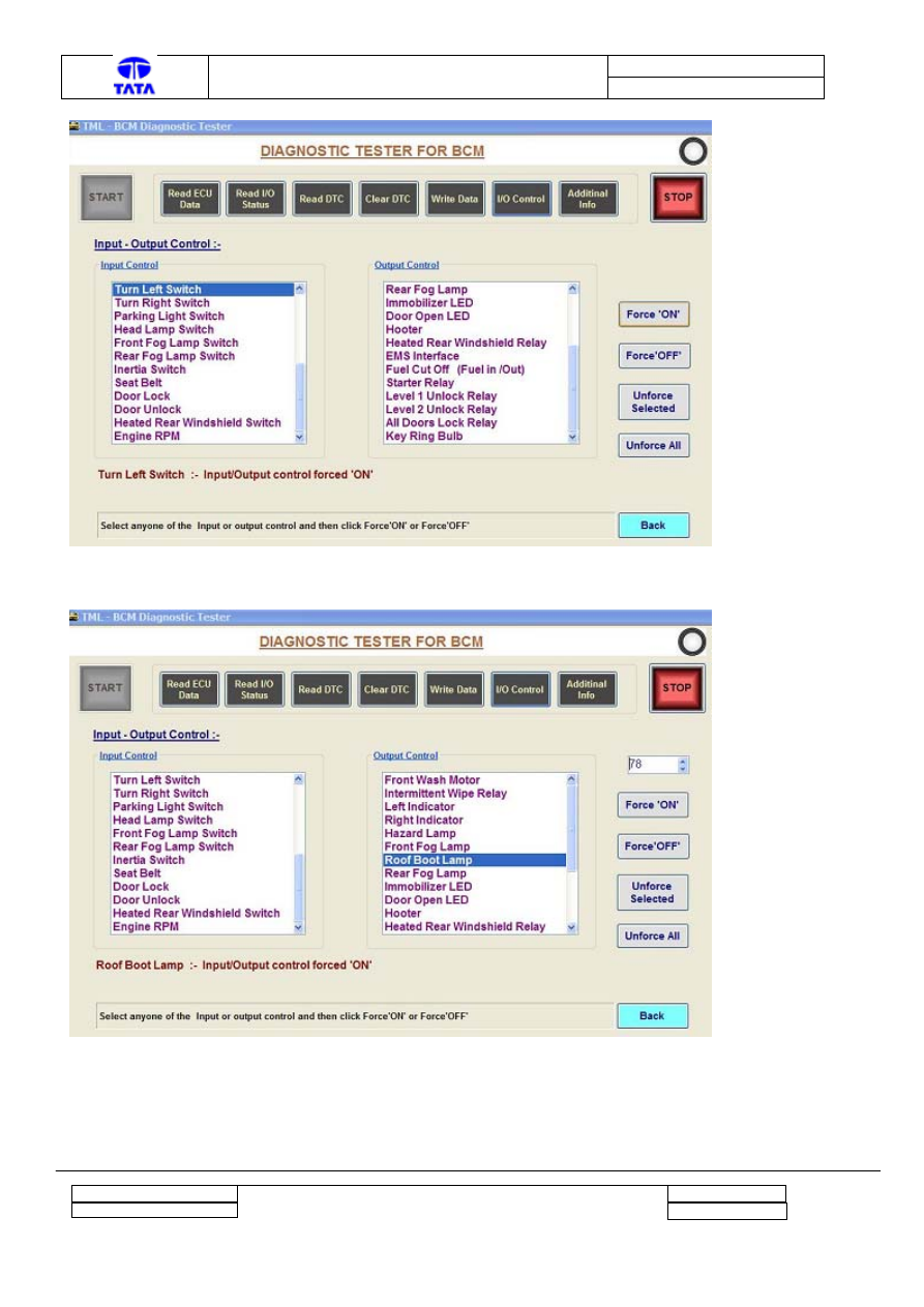
2.4
Force Input or / and Outputs
It is possible to force or unforce the inputs / outputs and assign analog / pulse input values
independently by selecting the I/O control button. The forced status is reverted back to the actual
status after the communication of the tester with the BCM is lost.
Refer following screen shots as an example. On the right hand side the Inputs are listed and on the
left hand side the outputs are listed. It is possible to force the particular Input or output to either
ON or OFF. The forced status can be reverted back to the actual status by pressing the “Unforce
all” button.
The “Turn Left Switch” input and “Roof Boot Lamp” output is selected in the two screens
respectively, as shown below. Note that it is possible to force the “Roof Boot Lamp” output with
the brightness level fro 0 to 100 %.
Project : Body Control Module
Copyright © with TATA MOTORS
This document must not be used in any way, such as copying and redistributing to third parties, without our consent
Dept : ERC - E & E
Page 7 of 27
Author : Anil Joshi
Doc. No.:
2101 2313 00 98
TML – Diagnostic Manual BCM
Version :
0.2
Project : Body Control Module
Copyright © with TATA MOTORS
This document must not be used in any way, such as copying and redistributing to third parties, without our consent
Dept : ERC - E & E
Page 8 of 27
Author : Anil Joshi
Doc. No.:
2101 2313 00 98
TML – Diagnostic Manual BCM
Version :
0.2
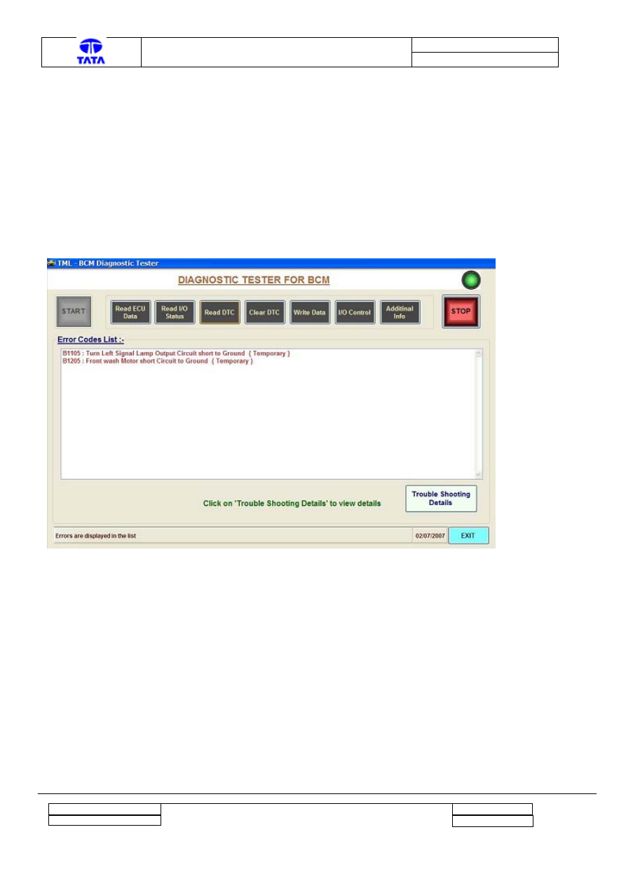
2.5
Read DTCs
The tool is capable of
a. Reading and Displaying error messages in the form of OBD codes
b. Reset/clear stored DTC
By clicking on Read DTC the following screen will be displayed. The set DTCs will be displayed
with the error code and the Description. After servicing the DTCs, it is to be cleared by using Clear
DTC button.
There is additional button provided on the screen called “Trouble shooting Details”. It contains the
flow charts for the troubleshooting.
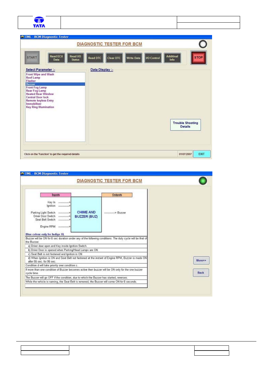
2.6
Additional information
The details of the BCM functions are available on this screen.
Project : Body Control Module
Copyright © with TATA MOTORS
This document must not be used in any way, such as copying and redistributing to third parties, without our consent
Dept : ERC - E & E
Page 9 of 27
Author : Anil Joshi
Doc. No.:
2101 2313 00 98
TML – Diagnostic Manual BCM
Version :
0.2
Similarly, the functional details are available for the other functions.
Project : Body Control Module
Copyright © with TATA MOTORS
This document must not be used in any way, such as copying and redistributing to third parties, without our consent
Dept : ERC - E & E
Page 10 of 27
Author : Anil Joshi

Doc. No.:
2101 2313 00 98
TML – Diagnostic Manual BCM
Version :
0.2
3 Help on debugging the fault
3.1
Steps for debugging the fault
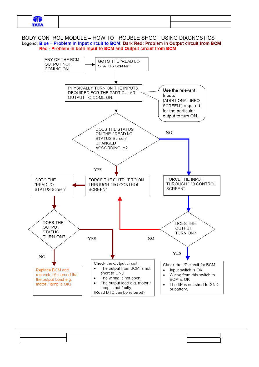
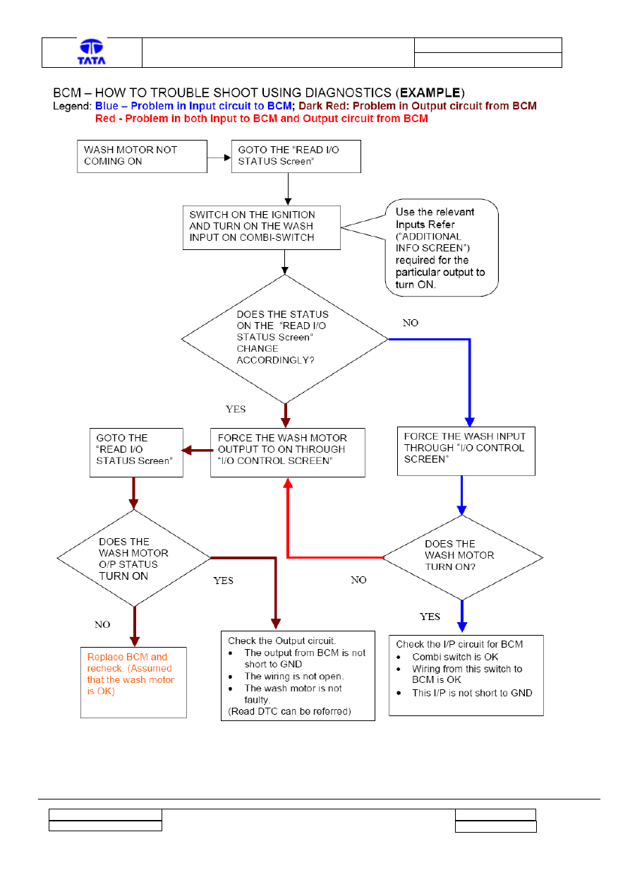
If any of the output is not becoming ON as expected, the steps involved in faultfinding are the
same. The flow charts are as given below. With the help of the Diagnostic Tester features
explained in the section 2 above, it is possible to locate the fault. The first flow chart is the generic
one, followed by the specific example.
Project : Body Control Module
Copyright © with TATA MOTORS
This document must not be used in any way, such as copying and redistributing to third parties, without our consent
Dept : ERC - E & E
Page 11 of 27
Author : Anil Joshi
Doc. No.:
2101 2313 00 98
TML – Diagnostic Manual BCM
Version :
0.2
Project : Body Control Module
Copyright © with TATA MOTORS
This document must not be used in any way, such as copying and redistributing to third parties, without our consent
Dept : ERC - E & E
Page 12 of 27
Author : Anil Joshi
Doc. No.:
2101 2313 00 98
TML – Diagnostic Manual BCM
Version :
0.2
Project : Body Control Module
Copyright © with TATA MOTORS
This document must not be used in any way, such as copying and redistributing to third parties, without our consent
Dept : ERC - E & E
Page 13 of 27
Author : Anil Joshi
Doc. No.:
2101 2313 00 98
TML – Diagnostic Manual BCM
Version :
0.2
3.2
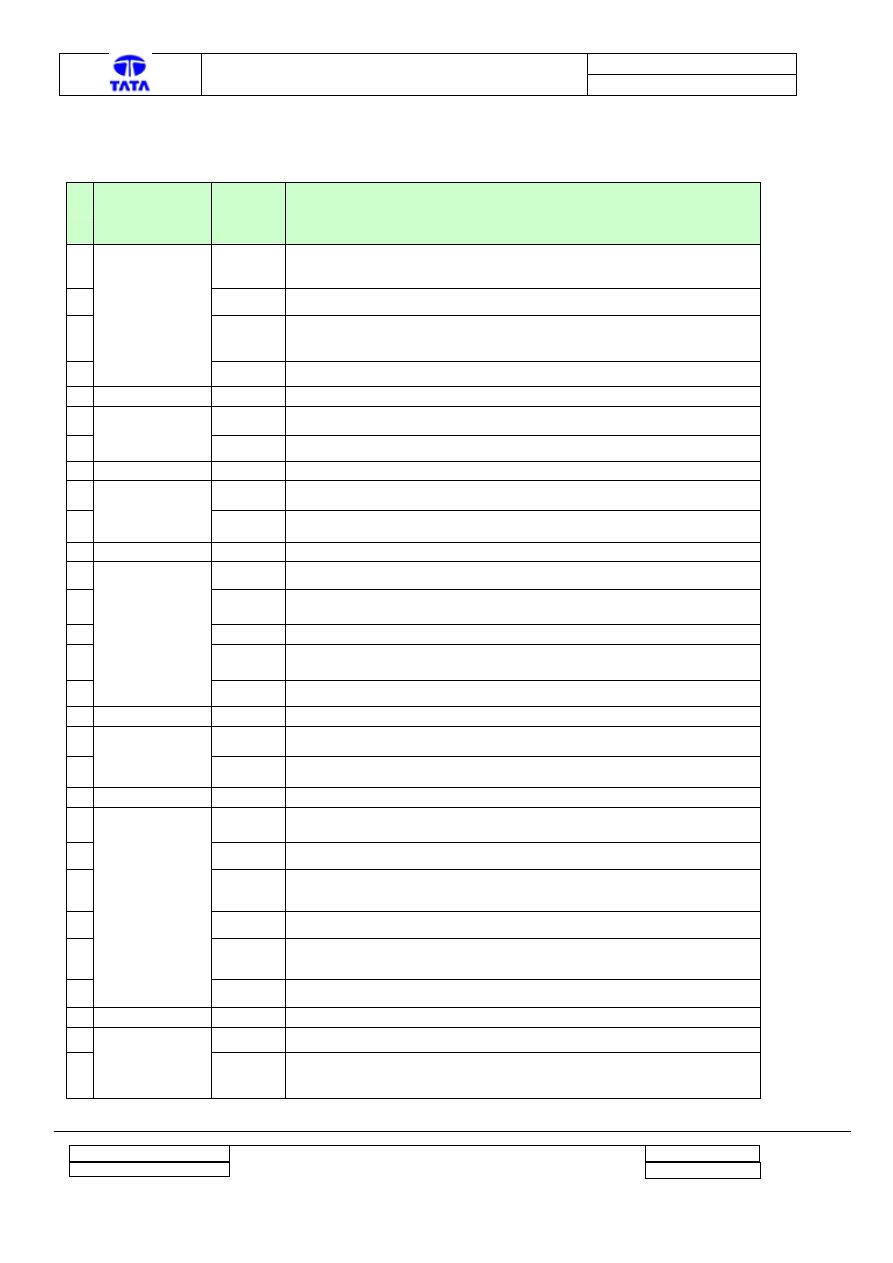
List of DTCs supported on the BCM
Sr.
No
Feature of BCM OBD code
to be
displayed
Description
1
B1104
Turn Left Signal Lamp Output Circuit short to Battery / Turn Left Signal
Lamp Output Circuit Open
2
B1105
Turn Left Signal Lamp Output Circuit short to Ground
3
B1107
Turn Right Signal Lamp Output Circuit short to Battery / Turn Right
Signal Lamp Output Circuit Open
4
Flasher
B1108
Turn Right Signal Lamp Output Circuit short to Ground
5
B1109
Front Fog Lamp Relay Coil short to Battery
6
Front fog lamp
B110A
Front Fog lamp output short to Ground / Front Fog lamp relay coil open
7
B110B
Rear fog lamp output short to Battery
8
Rear fog lamp
B110C
Rear fog lamp output short to ground / Lamp failure
9
B1201
Intermittent Wipe relay Coil short to Battery
10
B1202
Intermittent Wipe relay Coil short to Ground / Intermittent Wipe relay
Coil open
11
B1204
Front wash Motor Circuit short to Battery / Front wash Motor Circuit
failure
12
Front Wash and
Wipe
B1205
Front wash Motor short Circuit to Ground
13
B11A4
Key Ring Bulb output Short to Battery
14
Key Ring
Illumination
B11A5
Key Ring Bulb output short to ground / Key Ring Bulb output failure
15
B1300
All Door Lock output short to Ground / All Door Lock output failure
(Open Laod)
16
B1301
All Door Lock output short to Battery
17
B1302
Driver's Door Unlock Relay Circuit short to Ground / Driver's Door
Unlock Relay Circuit Failure (Open Laod)
18
B1303
Driver's Door Unlock Relay Circuit short to Battery
19
B1304
Level 2 Doors Unlock Relay Circuit short to Ground / Level 2 Doors
Unlock Relay Circuit Failure (Open Laod)
20
Central Door
Locking
B1305
Level 2 Doors Unlock Relay Circuit short to Battery
21
B1405
Heated Wind Shield Relay short to Battery
22
Heated Wind
Shield
B1406
Heated Wind Shield Relay output short to Ground / Heated Wind
Shield Relay Coil Circuit Failure
Project : Body Control Module
Copyright © with TATA MOTORS
This document must not be used in any way, such as copying and redistributing to third parties, without our consent
Dept : ERC - E & E
Page 14 of 27
Author : Anil Joshi
Doc. No.:
2101 2313 00 98
TML – Diagnostic Manual BCM
Version :
0.2
The above table lists the DTCs supported by the BCM. The list is common for both Indigo XL and
Xenon vehicle except the one. Key Ring Illumination DTC is applicable only for the Xenon
vehicle. The faults are displayed with the code and it’s description.
FAULT LOGGING STRATEGY: Maximum 16 DTCs can be logged in the BCM. Further DTC
can be logged only after clearing DTCs from the Tester.
The DTC will have the status either temporary or permanent. If the Fault has occurred for less than
or equal to 5 times, it is stored as Temporary fault otherwise it is it is stored as Permanent fault. If
the fault gets corrected then the outputs can be made ON.
3.3
Debugging Help on Specific error cases
3.3.1 Locking and unlocking not happening through Remote and Engine not starting
Operations: Using Read I/O status the problem can be identified. The three cases are mentioned
below.
NOTE: The Remote Key press status is displayed for one second in the RKE and Immobiliser
functions. Additionally the "RF Frame Received" status is also displayed.
Case A: The Normal case where the RKE function of BCM is OK.
Steps: 1) Go to Read I/O Staus on the Diagnosis Tool and select Remote Keyless Entry Function
2) Press Unlock / Lock key from Remote
Result: 1) Driver Door is unlocked / Locked.
2) Unlock / Lock status is changed to "Pressed" for one second.
3) RF Frame Received Status changed to "RF Frame Received".
Case B: The case where the “Not Learnt Remote” is used.
Steps: 1) Go to Read I/O Staus on the Diagnosis Tool and select Remote Keyless Entry Function
2) Press Unlock / Lock key from Remote
Result: 1) Driver Door is Not unlocked / Locked.
2) Unlock / Lock status remains as "Released".
3) RF Frame Received Status changed to "RF Frame Received".
Action required: Learn the remote with the BCM using the procedure as mentioned in the User
manual.
Project : Body Control Module
Copyright © with TATA MOTORS
This document must not be used in any way, such as copying and redistributing to third parties, without our consent
Dept : ERC - E & E
Page 15 of 27
Author : Anil Joshi
Doc. No.:
2101 2313 00 98
TML – Diagnostic Manual BCM
Version :
0.2
Case C: The error case where the RF Receiver is Faulty.
Steps: 1) Go to Read I/O Staus on the Diagnosis Tool and select Remote Keyless Entry Function
2) Press Unlock / Lock key from Remote
Result: 1) Driver Door is Not unlocked / Locked.
2) Unlock / Lock status remains as "Released".
3) RF Frame Received Status remains as "RF Frame Not Received".
Action required: Replace BCM.
NOTE: This software support is available from BCM Number 7001706 onwards for the Indigo XL
BCM.
3.3.2 Remote functioning is OK but Engine not starting
NOTE: Only applicable for Indigo XL.
Steps: 1) Go to Read I/O Staus on the Diagnosis Tool and select Immobiliser Function.
2) Observe Inertia input
Normally, the Inertia input status is Inactive. If so, it’s OK.
If it is Active then, the Starter is disabled and the Fuel relay is cut off (in case of petrol Engine).
The Inertia switch is supposed to get operated in case of vehicle crash (accident).
To confirm the observation
1) Force Inertia input to Inactive (OFF) by using “Control I/O” screen.
2) Crank the Engine
It should be possible to crank the Engine.
Action required: Make the Inertia switch Inactive by pressing it. The inertia switch is located
below the driver seat.
Project : Body Control Module
Copyright © with TATA MOTORS
This document must not be used in any way, such as copying and redistributing to third parties, without our consent
Dept : ERC - E & E
Page 16 of 27
Author : Anil Joshi
Doc. No.:
2101 2313 00 98
TML – Diagnostic Manual BCM
Version :
0.2
4 Appendix A for Indigo XL BCM
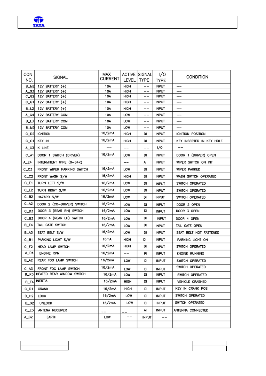
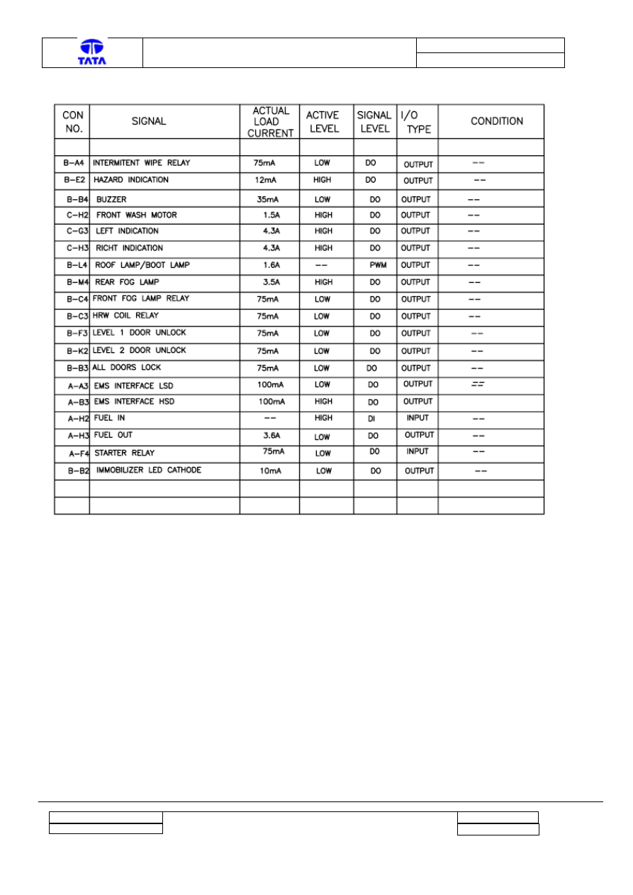
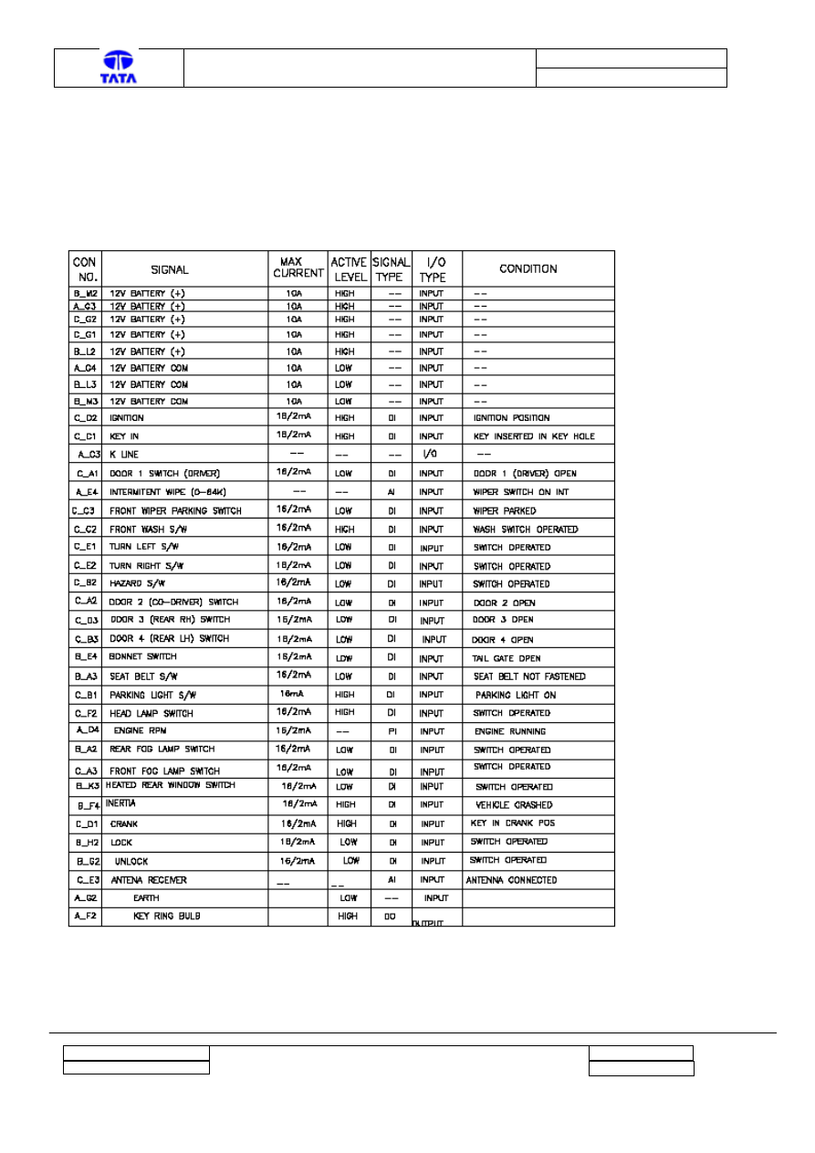
4.1
Connector Pin configuration (Indigo XL BCM)
Project : Body Control Module
Copyright © with TATA MOTORS
This document must not be used in any way, such as copying and redistributing to third parties, without our consent
Dept : ERC - E & E
Page 17 of 27
Author : Anil Joshi
Doc. No.:
2101 2313 00 98
TML – Diagnostic Manual BCM
Version :
0.2
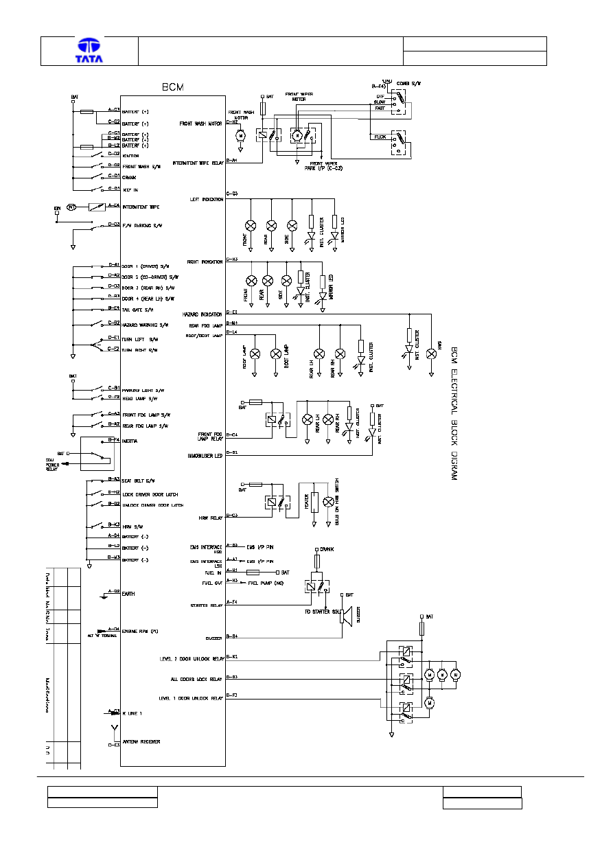
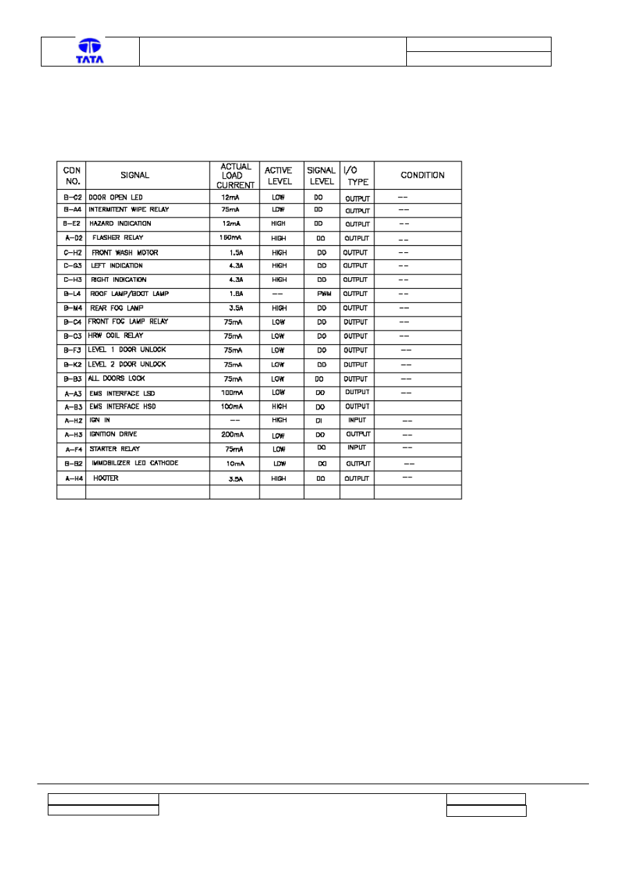
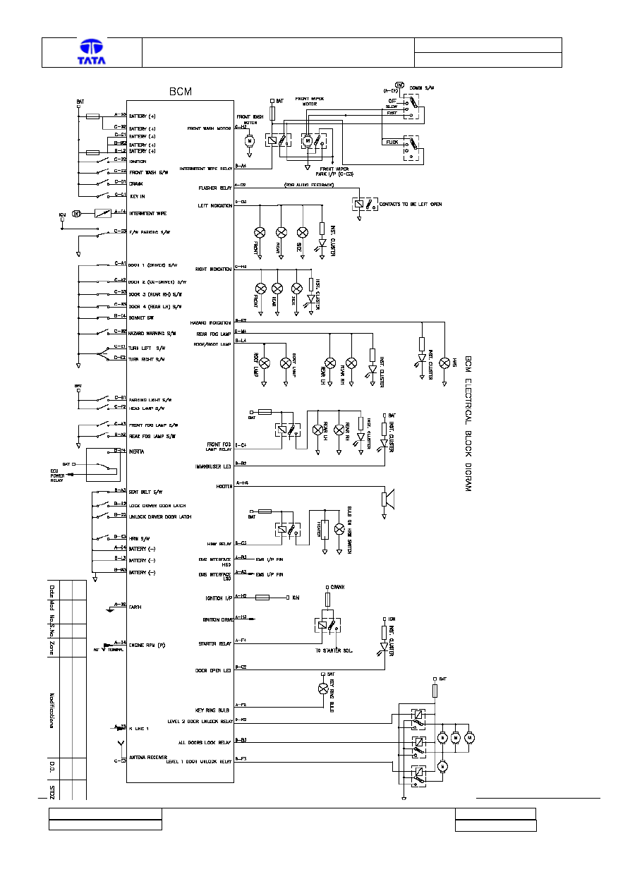
4.2
Block Input Output Diagram (Indigo XL BCM)
The Block diagram of the Inputs and Outputs is available on the next page.
Project : Body Control Module
Copyright © with TATA MOTORS
This document must not be used in any way, such as copying and redistributing to third parties, without our consent
Dept : ERC - E & E
Page 18 of 27
Author : Anil Joshi
Doc. No.:
2101 2313 00 98
TML – Diagnostic Manual BCM
Version :
0.2
Project : Body Control Module
Copyright © with TATA MOTORS
This document must not be used in any way, such as copying and redistributing to third parties, without our consent
Dept : ERC - E & E
Page 19 of 27
Author : Anil Joshi
Doc. No.:
2101 2313 00 98
TML – Diagnostic Manual BCM
Version :
0.2
4.3
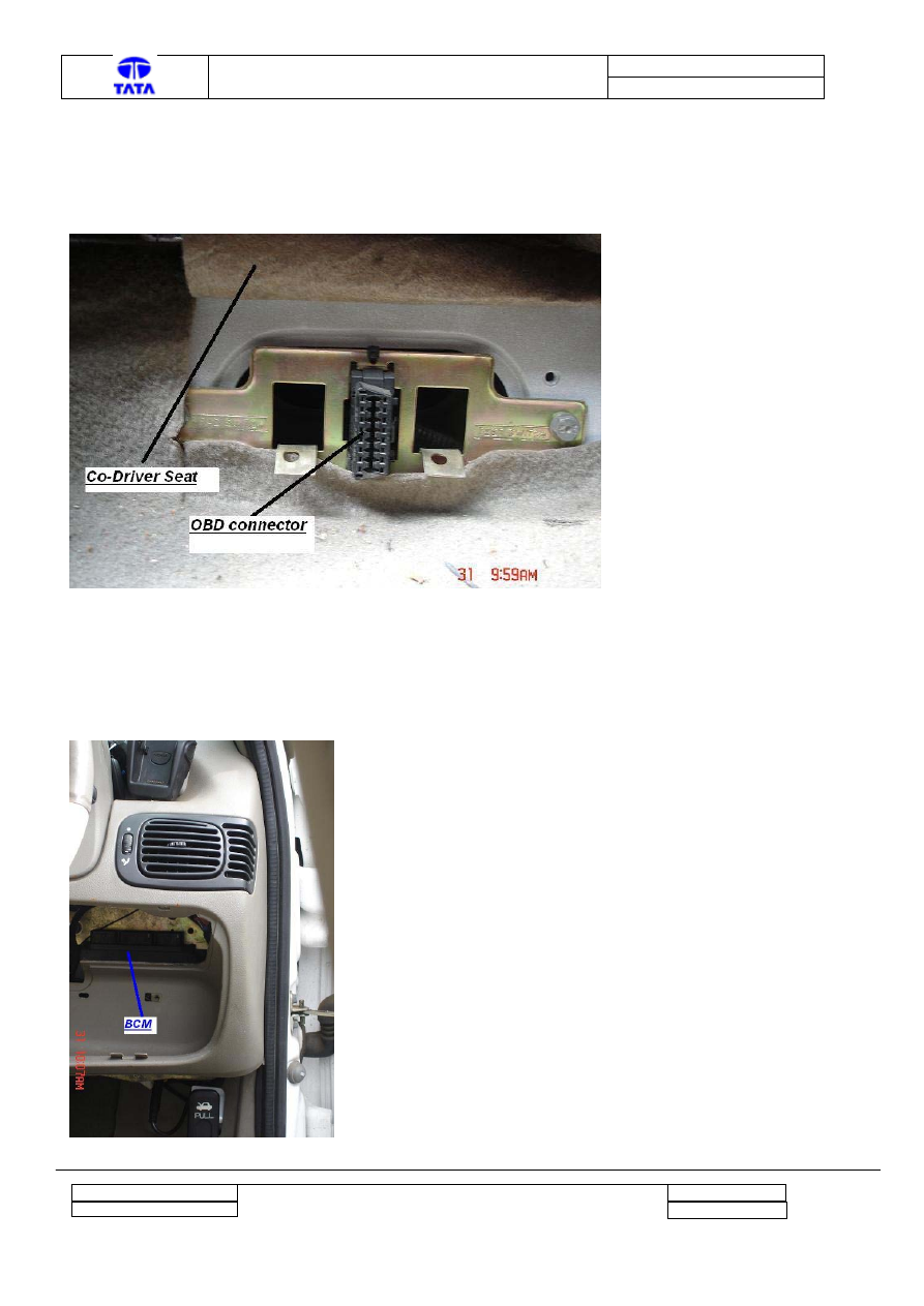
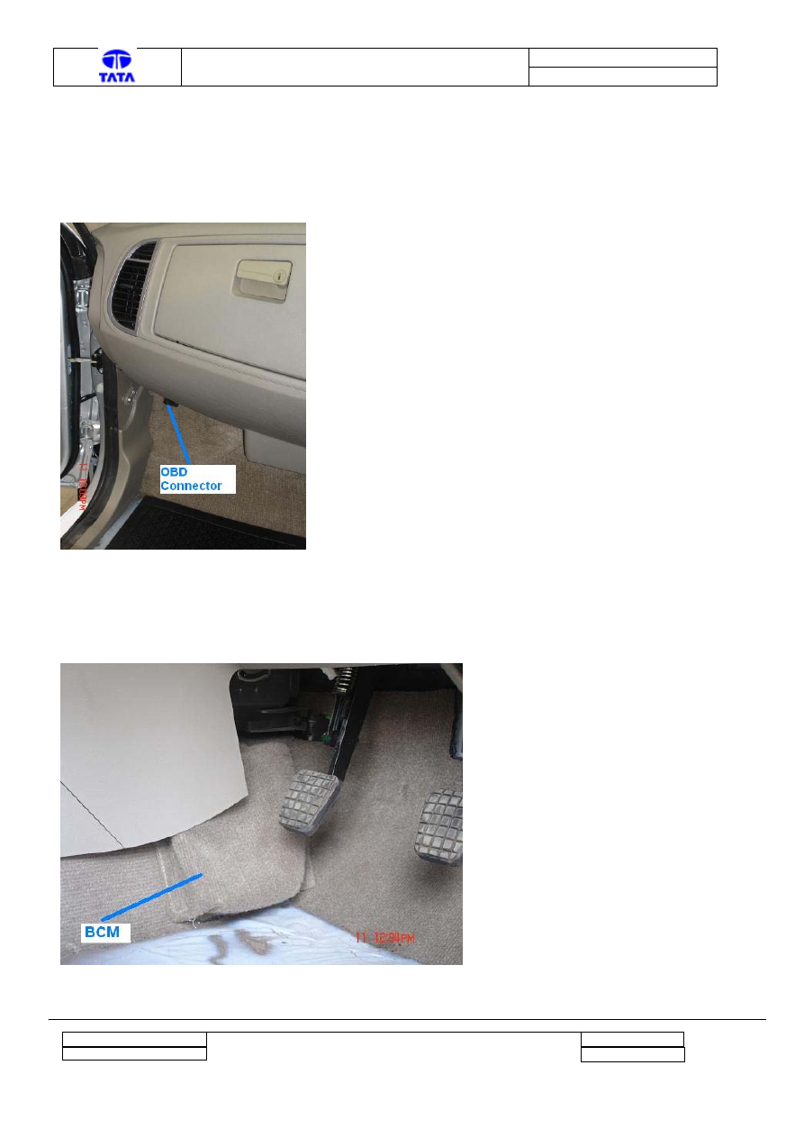
OBD connector location (Indigo XL BCM)
The Connector to be used for connecting Diagnosis Tester is located below the Co-Driver Seat in a
RHD vehicle. The snapshot is provided below for the easy reference.
4.4
BCM location (Indigo XL BCM)
The BCM is located below the dashboard beside the steering column. The snapshot is provided
below for the easy reference.
Project : Body Control Module
Copyright © with TATA MOTORS
This document must not be used in any way, such as copying and redistributing to third parties, without our consent
Dept : ERC - E & E
Page 20 of 27
Author : Anil Joshi
Doc. No.:
2101 2313 00 98
TML – Diagnostic Manual BCM
Version :
0.2
4.5
Breakpoint Information (Indigo XL BCM)
4.5.1 First
Breakpoint
Change: Started use of the improved RF receiver.
This modification is introduced from Sr. No 700 1900 dated 30.3.2007.
4.5.2 Second Breakpoint
Change: Software modification as a continuous improvement.
The modifications are as below:
CENTRAL DOOR LOCKING (Auto locking) – If doors are opened and closed within 5 sec.
after engine running (RPM >800), doors are not locked.
REMOTE KEYLESS ENTRY –
• If Master actuator is faulty, 4 flashes are given to inform the same, but Remote locking or
unlocking is possible.
• In lock state, if any Door was opened, the system will give 6 flashes as an indication of
intrusion when Unlock on Remote is pressed.
• If the Inertia switch is operated, system will give 5 flashes when Unlock is pressed as an
indication of the active state of inertia switch.
IMMOBILISER – In lock state, if Ignition or Crank was made ON, the system will give 6 flashes
as an indication of intrusion when Unlock button on Remote is pressed.
EMERGENCY DISARMING - For Emergency Pin-Override and Learning of Remotes, the
Immobiliser LED was being used for counting of the digits. Instead, the Side Indicator Lamps
(along with the Cluster tell tales) are used for counting digits.
This modification has been introduced from Sr. No 7003601 dated 25.7.2007. These units are also
identified by updated sticker on housing.
Project : Body Control Module
Copyright © with TATA MOTORS
This document must not be used in any way, such as copying and redistributing to third parties, without our consent
Dept : ERC - E & E
Page 21 of 27
Author : Anil Joshi
Doc. No.:
2101 2313 00 98
TML – Diagnostic Manual BCM
Version :
0.2
5 Appendix B for Xenon BCM
5.1
Connector Pin configuration (Xenon BCM)
Project : Body Control Module
Copyright © with TATA MOTORS
This document must not be used in any way, such as copying and redistributing to third parties, without our consent
Dept : ERC - E & E
Page 22 of 27
Author : Anil Joshi
Doc. No.:
2101 2313 00 98
TML – Diagnostic Manual BCM
Version :
0.2
5.2
Block Input Output Diagram (Xenon BCM)
The Block diagram of the Inputs and Outputs is available on the next page.
Project : Body Control Module
Copyright © with TATA MOTORS
This document must not be used in any way, such as copying and redistributing to third parties, without our consent
Dept : ERC - E & E
Page 23 of 27
Author : Anil Joshi
Doc. No.:
2101 2313 00 98
TML – Diagnostic Manual BCM
Version :
0.2
Project : Body Control Module
Copyright © with TATA MOTORS
This document must not be used in any way, such as copying and redistributing to third parties, without our consent
Page 24 of 27
Author : Anil Joshi
Dept : ERC - E & E
Doc. No.:
2101 2313 00 98
TML – Diagnostic Manual BCM
Version :
0.2
5.3
OBD connector location (Xenon BCM)
The Connector to be used for connecting Diagnosis Tester is located in the cabin near the left door.
In RHD vehicle, it is in front of the Co-Driver seat. The snapshot is provided below for the easy
reference.
5.4
BCM location (Xenon BCM)
The BCM is located on the left of the clutch pedal in a RHD vehicle. The snapshot is provided
below for the easy reference.
Project : Body Control Module
Copyright © with TATA MOTORS
This document must not be used in any way, such as copying and redistributing to third parties, without our consent
Dept : ERC - E & E
Page 25 of 27
Author : Anil Joshi

Doc. No.:
2101 2313 00 98
TML – Diagnostic Manual BCM
Version :
0.2
5.5
Breakpoint Information (Xenon BCM)
5.5.1 First
Breakpoint
Change: Software modification as a continuous improvement.
The modifications are as below:
CENTRAL DOOR LOCKING (Auto locking) – If doors are opened and closed within 5 sec.
after engine running (RPM >800), doors are not locked.
REMOTE KEYLESS ENTRY - In lock state if any Door was opened, the system will give 6
flashes as an indication of intrusion when Unlock on Remote is pressed.
IMMOBILISER– In lock state if Ignition or Crank was made ON, the system will give 6 flashes
as an indication of intrusion when Unlock button on Remote is pressed.
EMERGENCY DISARMING - For Emergency Pin-Override and Learning of Remotes, the
Immobiliser LED was being used for counting of the digits. Instead, the Side Indicator Lamps
(along with the Cluster tell tales) are used for counting digits.
This modification has been introduced from Sr. No 700 0176 dated 2.7.2007. These units are also
identified with TWO BLUE DOTS on connector and updated sticker on connector.
Project : Body Control Module
Copyright © with TATA MOTORS
This document must not be used in any way, such as copying and redistributing to third parties, without our consent
Dept : ERC - E & E
Page 26 of 27
Author : Anil Joshi
Doc. No.:
2101 2313 00 98
TML – Diagnostic Manual BCM
Version :
0.2
6 Reference
Documents
Sr.
No.
Document Name
Version and date
Description
Project : Body Control Module
Copyright © with TATA MOTORS
This document must not be used in any way, such as copying and redistributing to third parties, without our consent
Dept : ERC - E & E
Page 27 of 27
Author : Anil Joshi
Document Outline
- Diagnostic Manual for BCM
- PURPOSE: This document details the Diagnostic Procedure for
- Xenon vehicles.
- NOTE: This document is subject to change based on the BCM Ha
- Prepared by
- Approved by
- Date
- Reason For Changes
- Ver
- Anil Joshi
- Sanjeev Maralihalli
- 04-July-07
- First version
- 0.1
- Anil Joshi
- Sanjeev Maralihalli
- 12-Sep-07
- The case of Engine not starting due to Inertia active is add
- Snapshots of the OBD Connector and BCM locations are added.
- The Break point information for BCM is added.
- 0.2
- Index
- 1 Introduction 4
- 2 Features of the Tool 4
- 2.1 BCM type selection 4
- 2.2 Read / Write BCM and Vehicle Identification 4
- 2.3 Monitor Inputs and Outputs of BCM function 6
- 2.4 Force Input or / and Outputs 7
- 2.5 Read DTCs 9
- 2.6 Additional information 9
- 3 Help on debugging the fault 11
- 3.1 Steps for debugging the fault 11
- 3.2 List of DTCs supported on the BCM 14
- 3.3 Debugging Help on Specific error cases 15
- 3.3.1 Locking and unlocking not happening through Remote and
- 3.3.2 Remote functioning is OK but Engine not starting 16
- 4 Appendix A for Indigo XL BCM 17
- 4.1 Connector Pin configuration (Indigo XL BCM) 17
- 4.2 Block Input Output Diagram (Indigo XL BCM) 18
- 4.3 OBD connector location (Indigo XL BCM) 20
- 4.4 BCM location (Indigo XL BCM) 20
- 4.5 Breakpoint Information (Indigo XL BCM) 21
- 4.5.1 First Breakpoint 21
- 4.5.2 Second Breakpoint 21
- 5 Appendix B for Xenon BCM 22
- 5.1 Connector Pin configuration (Xenon BCM) 22
- 5.2 Block Input Output Diagram (Xenon BCM) 23
- 5.3 OBD connector location (Xenon BCM) 25
- 5.4 BCM location (Xenon BCM) 25
- 5.5 Breakpoint Information (Xenon BCM) 26
- 5.5.1 First Breakpoint 26
- 6 Reference Documents 27
- Introduction
- This document gives information about the Diagnosis Tool cal
- Features of the Tool
- The Diagnosis Tool is common for the Indigo XL and Xenon veh
- The screen shot is as shown below.
- It is possible to Write or Read the following data into / fr
- VIN (Read /Write)
- VC (Read /Write)
- BCM Identification (Read Only)
- BCM type (Read Only)
- Note: The VC number is presently unused on both the vehicles
- By selecting Read ECU Data, the following screen is displaye
- The VIN number can be written into the BCM in case of BCM re
- The screen is provided for selecting one of the BCM Function
- All inputs and outputs including analog, digital and pulse c
- The screen shot is as shown below.
- It is possible to force or unforce the inputs / outputs and
- Refer following screen shots as an example. On the right han
- The “Turn Left Switch” input and “Roof Boot Lamp” output is
- The tool is capable of
- Reading and Displaying error messages in the form of OBD cod
- Reset/clear stored DTC
- By clicking on Read DTC the following screen will be display
- There is additional button provided on the screen called “Tr
- The details of the BCM functions are available on this scree
- Similarly, the functional details are available for the othe
- Help on debugging the fault
- If any of the output is not becoming ON as expected, the ste
- Sr.No
- Feature of BCM
- OBD code to be displayed
- Description
- 1
- Flasher
- B1104
- Turn Left Signal Lamp Output Circuit short to Battery / Turn
- 2
- B1105
- Turn Left Signal Lamp Output Circuit short to Ground
- 3
- B1107
- Turn Right Signal Lamp Output Circuit short to Battery / Tur
- 4
- B1108
- Turn Right Signal Lamp Output Circuit short to Ground
- 5
- Front fog lamp
- B1109
- Front Fog Lamp Relay Coil short to Battery
- 6
- B110A
- Front Fog lamp output short to Ground / Front Fog lamp relay
- 7
- Rear fog lamp
- B110B
- Rear fog lamp output short to Battery
- 8
- B110C
- Rear fog lamp output short to ground / Lamp failure
- 9
- Front Wash and Wipe
- B1201
- Intermittent Wipe relay Coil short to Battery
- 10
- B1202
- Intermittent Wipe relay Coil short to Ground / Intermittent
- 11
- B1204
- Front wash Motor Circuit short to Battery / Front wash Motor
- 12
- B1205
- Front wash Motor short Circuit to Ground
- 13
- Key Ring Illumination
- B11A4
- Key Ring Bulb output Short to Battery
- 14
- B11A5
- Key Ring Bulb output short to ground / Key Ring Bulb output
- 15
- Central Door Locking
- B1300
- All Door Lock output short to Ground / All Door Lock output
- 16
- B1301
- All Door Lock output short to Battery
- 17
- B1302
- Driver's Door Unlock Relay Circuit short to Ground / Driver'
- 18
- B1303
- Driver's Door Unlock Relay Circuit short to Battery
- 19
- B1304
- Level 2 Doors Unlock Relay Circuit short to Ground / Level 2
- 20
- B1305
- Level 2 Doors Unlock Relay Circuit short to Battery
- 21
- Heated Wind Shield
- B1405
- Heated Wind Shield Relay short to Battery
- 22
- B1406
- Heated Wind Shield Relay output short to Ground / Heated Win
- The above table lists the DTCs supported by the BCM. The lis
- FAULT LOGGING STRATEGY: Maximum 16 DTCs can be logged in the
- The DTC will have the status either temporary or permanent.
- Operations: Using Read I/O status the problem can be identif
- NOTE: The Remote Key press status is displayed for one secon
- Case A: The Normal case where the RKE function of BCM is OK.
- Steps: 1) Go to Read I/O Staus on the Diagnosis Tool and select Remote Keyless Entry Function
- 2) Press Unlock / Lock key from Remote
- Result: 1) Driver Door is unlocked / Locked.
- 2) Unlock / Lock status is changed to "Pressed" for one second.
- 3) RF Frame Received Status changed to "RF Frame Received".
- Case B: The case where the “Not Learnt Remote” is used.
- Steps: 1) Go to Read I/O Staus on the Diagnosis Tool and select Remote Keyless Entry Function
- 2) Press Unlock / Lock key from Remote
- Result: 1) Driver Door is Not unlocked / Locked.
- 2) Unlock / Lock status remains as "Released".
- 3) RF Frame Received Status changed to "RF Frame Received".
- Action required: Learn the remote with the BCM using the pro
- Case C: The error case where the RF Receiver is Faulty.
- Steps: 1) Go to Read I/O Staus on the Diagnosis Tool and select Remote Keyless Entry Function
- 2) Press Unlock / Lock key from Remote
- Result: 1) Driver Door is Not unlocked / Locked.
- 2) Unlock / Lock status remains as "Released".
- 3) RF Frame Received Status remains as "RF Frame Not Received".
- Action required: Replace BCM.
- NOTE: This software support is available from BCM Number 700
- NOTE: Only applicable for Indigo XL.
- Steps: 1) Go to Read I/O Staus on the Diagnosis Tool and select Immobiliser Function.
- 2) Observe Inertia input
- Normally, the Inertia input status is Inactive. If so, it’s
- If it is Active then, the Starter is disabled and the Fuel r
- The Inertia switch is supposed to get operated in case of ve
- To confirm the observation
- Force Inertia input to Inactive (OFF) by using “Control I/O”
- Crank the Engine
- It should be possible to crank the Engine.
- Action required: Make the Inertia switch Inactive by pressin
- Appendix A for Indigo XL BCM
- The Block diagram of the Inputs and Outputs is available on
- The Connector to be used for connecting Diagnosis Tester is
- The BCM is located below the dashboard beside the steering c
- Change: Started use of the improved RF receiver.
- This modification is introduced from Sr. No 700 1900 dated 3
- Change: Software modification as a continuous improvement.
- The modifications are as below:
- CENTRAL DOOR LOCKING (Auto locking) – If doors are opened an
- REMOTE KEYLESS ENTRY –
- If Master actuator is faulty, 4 flashes are given to inform
- In lock state, if any Door was opened, the system will give
- If the Inertia switch is operated, system will give 5 flashe
- IMMOBILISER – In lock state, if Ignition or Crank was made O
- EMERGENCY DISARMING - For Emergency Pin-Override and Learnin
- This modification has been introduced from Sr. No 7003601 da
- Appendix B for Xenon BCM
- The Block diagram of the Inputs and Outputs is available on
- The Connector to be used for connecting Diagnosis Tester is
- The BCM is located on the left of the clutch pedal in a RHD
- Change: Software modification as a continuous improvement.
- The modifications are as below:
- CENTRAL DOOR LOCKING (Auto locking) – If doors are opened an
- REMOTE KEYLESS ENTRY - In lock state if any Door was opened,
- IMMOBILISER– In lock state if Ignition or Crank was made ON,
- EMERGENCY DISARMING - For Emergency Pin-Override and Learnin
- This modification has been introduced from Sr. No 700 0176 d
- Reference Documents
- Sr. No.
- Document Name
- Version and date
- Description
Wyszukiwarka
Podobne podstrony:
C5 (X7) D6AY01KAP0 9 23 07 2013 Pomoc w diagnostyce Manualna (mechaniczna) skrzynia biegów i sp
Diagnostic Manual A ECU
original c68 retail diy auto diagnostic tool manual
diagnostyka i techniki w terapii manualnej
zajęcia 1 techniki i diagnozy terapii manualnej-druk, terapia manualna
Techniki diagnozy i terapii manualnej
Diagnostyka usterek sprzęgła, - !!! SKRZYNIE BIIEGÓW AUTOMATYCZNE I MANUALNE !!! -
original c68 retail diy auto diagnostic tool manual
The Merck Manual Objawy kliniczne Praktyczny przewodnik diagnost Kaminski Bogdan Klin Zuzanna Ksiad
diagnostyka
T 3[1] METODY DIAGNOZOWANIA I ROZWIAZYWANIA PROBLEMOW
Przedmiot PRI i jego diagnoza przegląd koncepcji temperamentu
DIAGNOSTYKA FIZJOLOGICZNA I 1
Dyslipidemie diagnoza JH
więcej podobnych podstron