Multifunction Electronic Modules - Driver Door Module (DDM)
Mondeo 2007.5 (02/2007-)
Diagnosis and Testing
Special Tool(s)
General Equipment
Inspection and Testing
1.
1. VERIFY the customer concern.
2.
2. Visually CHECK for any obvious mechanical or electrical damage.
Visual Inspection
3.
3. RECTIFY any obvious causes for a concern found during the visual inspection before performing any further tests. CHECK the operation of the
system.
4.
4. If the concern persists after the visual inspection, PERFORM a fault diagnosis with the diagnostic unit, RECTIFY any displayed faults in accordance
with the displayed fault description and then DELETE the displayed fault(s). CHECK the operation of the system.
5.
5. For vehicles with no stored fault(s), PROCEED in accordance with the Symptom Chart according to the fault symptom.
6.
6. Following checking or elimination of the fault and after completion of operations, the fault memories of all vehicle modules must be READ OUT and
any stored faults must be DELETED. READ OUT all fault memories again following a road test.
Diagnostic Trouble Code (DTC) Index
Terminal Probe Kit
418-S035
Digital multimeter
Ford Diagnostic Equipment
Electrical
Fuses.
Wiring harness.
Electrical connectors.
DTC
Description
Action
B1189-29
Signal error, position sensor for the front electric
window regulator.
REFER to:
Glass, Frames and Mechanisms
(501-11 Glass, Frames and
Mechanisms, Diagnosis and Testing).
B118A-29
Signal error, position sensor for the rear electric
window regulator.
REFER to:
Glass, Frames and Mechanisms
(501-11 Glass, Frames and
Mechanisms, Diagnosis and Testing).
C1B14-15
Circuit of the position sensor for the front electric
window regulator defective (short to voltage or open
circuit).
REFER to:
Glass, Frames and Mechanisms
(501-11 Glass, Frames and
Mechanisms, Diagnosis and Testing).
C1B14-11
Circuit of the position sensor for the front electric
window regulator defective (short to ground).
REFER to:
Glass, Frames and Mechanisms
(501-11 Glass, Frames and
Mechanisms, Diagnosis and Testing).
C1B15-15
Circuit of the position sensor for the front electric
window regulator defective (short to voltage or open
circuit).
REFER to:
Glass, Frames and Mechanisms
(501-11 Glass, Frames and
Mechanisms, Diagnosis and Testing).
C1B15-11
Circuit of the position sensor for the front electric
window regulator defective (short to ground).
REFER to:
Glass, Frames and Mechanisms
(501-11 Glass, Frames and
Mechanisms, Diagnosis and Testing).
B1C13-15
Feedback circuit for up/down adjustment of the motor
for the electrically adjustable exterior mirror on the
driver side faulty (short to voltage or open circuit).
REFER to:
Rear View Mirrors
(501-09 Rear View Mirrors, Diagnosis and Testing).
B1C13-11
Feedback circuit for up/down adjustment of the motor
for the electrically adjustable exterior mirror on the
driver side faulty (short to ground).
REFER to:
Rear View Mirrors
(501-09 Rear View Mirrors, Diagnosis and Testing).
B1C14-15
Feedback circuit for left/right adjustment of the motor
for the electrically adjustable exterior mirror on the
driver side faulty (short to voltage or open circuit).
REFER to:
Rear View Mirrors
(501-09 Rear View Mirrors, Diagnosis and Testing).
B1C14-11
Feedback circuit for left/right adjustment of the motor
for the electrically adjustable exterior mirror on the
driver side faulty (short to ground).
REFER to:
Rear View Mirrors
(501-09 Rear View Mirrors, Diagnosis and Testing).
B1C15-15
Feedback circuit for up/down adjustment of the motor
for the electrically adjustable exterior mirror on the
passenger side faulty (short to voltage or open circuit).
REFER to:
Rear View Mirrors
(501-09 Rear View Mirrors, Diagnosis and Testing).
B1C15-11
Feedback circuit for up/down adjustment of the motor
for the electrically adjustable exterior mirror on the
passenger side faulty (short to ground).
REFER to:
Rear View Mirrors
(501-09 Rear View Mirrors, Diagnosis and Testing).
B1C16-15
Feedback circuit for left/right adjustment of the motor
for the electrically adjustable exterior mirror on the
passenger side faulty (short to voltage or open circuit).
REFER to:
Rear View Mirrors
(501-09 Rear View Mirrors, Diagnosis and Testing).
B1C16-11
Feedback circuit for left/right adjustment of the motor
for the electrically adjustable exterior mirror on the
passenger side faulty (short to ground).
REFER to:
Rear View Mirrors
(501-09 Rear View Mirrors, Diagnosis and Testing).
U2100-00, U2101-00,
U2012-08, U3002-55,
U3002-81
Module configuration faulty.
Make sure that the latest release of the software is loaded in the diagnostic unit
and that the correct variant is installed. CONFIGURE the driver door module
again using the Ford diagnostic equipment. If the fault occurs again, INSTALL a
new driver door module.
U2014-44, U3000-49,
U0300-00
Internal control unit fault.
Make sure that the latest release of the software is loaded in the diagnostic unit
and that the correct variant is installed. CONFIGURE the driver door module
again using the Ford diagnostic equipment. If the fault occurs again, INSTALL a
new driver door module.
B117E-73
Circuit of the front electric window regulator faulty
(window cannot be closed).
REFER to:
Glass, Frames and Mechanisms
(501-11 Glass, Frames and
Mechanisms, Diagnosis and Testing).
B117E-72
Circuit of the front electric window regulator faulty
(window cannot be closed).
REFER to:
Glass, Frames and Mechanisms
(501-11 Glass, Frames and
Mechanisms, Diagnosis and Testing).
B117E-07
Circuit of the front electric window regulator faulty
(mechanical fault).
REFER to:
Glass, Frames and Mechanisms
(501-11 Glass, Frames and
Mechanisms, Diagnosis and Testing).
B117F-73
Circuit of the front electric window regulator faulty
(window cannot be opened).
REFER to:
Glass, Frames and Mechanisms
(501-11 Glass, Frames and
Mechanisms, Diagnosis and Testing).
B117F-72
Circuit of the front electric window regulator faulty
(window cannot be opened).
REFER to:
Glass, Frames and Mechanisms
(501-11 Glass, Frames and
Mechanisms, Diagnosis and Testing).
Strona 1 z 16
2012-08-11
http://127.0.0.1:8888/wsm/js/procedure.do?variantId=1449&proc-uid=G927147&gui...

B117C-73
Circuit of the rear electric window regulator faulty
(window cannot be closed).
REFER to:
Glass, Frames and Mechanisms
(501-11 Glass, Frames and
Mechanisms, Diagnosis and Testing).
B117C-72
Circuit of the rear electric window regulator faulty
(window cannot be closed).
REFER to:
Glass, Frames and Mechanisms
(501-11 Glass, Frames and
Mechanisms, Diagnosis and Testing).
B117C-07
Circuit of the rear electric window regulator faulty
(mechanical fault).
REFER to:
Glass, Frames and Mechanisms
(501-11 Glass, Frames and
Mechanisms, Diagnosis and Testing).
B117D-73
Circuit of the rear electric window regulator faulty
(window cannot be opened).
REFER to:
Glass, Frames and Mechanisms
(501-11 Glass, Frames and
Mechanisms, Diagnosis and Testing).
B117D-72
Circuit of the rear electric window regulator faulty
(window cannot be opened).
REFER to:
Glass, Frames and Mechanisms
(501-11 Glass, Frames and
Mechanisms, Diagnosis and Testing).
B1108-11
Circuit of driver central locking motor faulty (short to
ground).
GO to Pinpoint Test
D.
B1108-15
Circuit of driver central locking motor faulty (short to
voltage or open circuit).
GO to Pinpoint Test
D.
B10EB-11
Circuit of driver central locking motor with double
locking faulty (short to ground).
GO to Pinpoint Test
E.
B10EB-15
Circuit of driver central locking motor with double
locking faulty (short to voltage or open circuit).
GO to Pinpoint Test
E.
U2013-24
Driver door switch unit faulty.
REFER to:
Glass, Frames and Mechanisms
(501-11 Glass, Frames and
Mechanisms, Diagnosis and Testing).
U2002-24
Passenger front door switch unit faulty.
REFER to:
Glass, Frames and Mechanisms
(501-11 Glass, Frames and
Mechanisms, Diagnosis and Testing).
U2004-24
Rear door switch unit faulty, driver side/passenger side REFER to:
Glass, Frames and Mechanisms
(501-11 Glass, Frames and
Mechanisms, Diagnosis and Testing).
B1109-11
Circuit of the passenger central locking motor faulty
(short to ground).
GO to Pinpoint Test
C.
B1109-15
Circuit of the passenger central locking motor faulty
(short to voltage or open circuit).
GO to Pinpoint Test
C.
B10EC-11
Circuit of the passenger central locking motor with
double locking faulty (short to ground).
GO to Pinpoint Test
F.
B10EC-15
Circuit of the passenger central locking motor with
double locking faulty (short to voltage or open circuit).
GO to Pinpoint Test
F.
B110A-11
Circuit of the left rear central locking motor faulty
(short to ground).
GO to Pinpoint Test
H.
B110A-15
Circuit of the left rear central locking motor faulty
(short to voltage or open circuit).
GO to Pinpoint Test
H.
B10ED-11
Circuit of the left rear central locking motor with double
locking faulty (short to ground).
GO to Pinpoint Test
I.
B10ED-15
Circuit of the left rear central locking motor with double
locking faulty (short to voltage or open circuit).
GO to Pinpoint Test
I.
B110B-11
Circuit of the right rear central locking motor faulty
(short to ground).
GO to Pinpoint Test
G.
B110B-15
Circuit of the right rear central locking motor faulty
(short to voltage or open circuit).
GO to Pinpoint Test
G.
B10EE-11
Circuit of the right rear central locking motor with
double locking faulty (short to ground).
GO to Pinpoint Test
J.
B10EE-15
Circuit of the right rear central locking motor with
double locking faulty (short to voltage or open circuit).
GO to Pinpoint Test
J.
B108F-23
Circuit of the passenger compartment
locking/unlocking switch faulty.
GO to Pinpoint Test
K.
B1C10-11
Circuit for up/down adjustment of the motor for the
electrically adjustable exterior mirror on the driver side
faulty (short to ground).
REFER to:
Rear View Mirrors
(501-09 Rear View Mirrors, Diagnosis and Testing).
B1C09-11
Circuit for left/right adjustment of the motor for the
electrically adjustable exterior mirror on the driver side
faulty (short to ground).
REFER to:
Rear View Mirrors
(501-09 Rear View Mirrors, Diagnosis and Testing).
B1C11-11
Circuit for left/right adjustment of the motor for the
electrically adjustable exterior mirror on the passenger
side faulty (short to ground).
REFER to:
Rear View Mirrors
(501-09 Rear View Mirrors, Diagnosis and Testing).
B1C12-11
Circuit for up/down adjustment of the motor for the
electrically adjustable exterior mirror on the passenger
side faulty (short to ground).
REFER to:
Rear View Mirrors
(501-09 Rear View Mirrors, Diagnosis and Testing).
B1163-11
Circuit of left-hand heated exterior mirror faulty (short
to ground).
REFER to:
Rear View Mirrors
(501-09 Rear View Mirrors, Diagnosis and Testing).
B1163-15
Circuit of left-hand heated exterior mirror faulty (short
to voltage or open circuit).
REFER to:
Rear View Mirrors
(501-09 Rear View Mirrors, Diagnosis and Testing).
B1164-11
Circuit of right-hand heated exterior mirror faulty
(short to ground).
REFER to:
Rear View Mirrors
(501-09 Rear View Mirrors, Diagnosis and Testing).
B1164-15
Circuit of right-hand heated exterior mirror faulty
(short to voltage or open circuit).
REFER to:
Rear View Mirrors
(501-09 Rear View Mirrors, Diagnosis and Testing).
B1165-15
Circuit of courtesy lamps integrated in the left-hand
exterior mirror faulty (short to voltage or open circuit).
REFER to:
Parking, Rear and License Plate Lamps
(417-01 Exterior Lighting,
Diagnosis and Testing).
B1165-11
Circuit of courtesy lamps integrated in the left-hand
exterior mirror faulty (short to ground).
REFER to:
Parking, Rear and License Plate Lamps
(417-01 Exterior Lighting,
Diagnosis and Testing).
B1166-15
Circuit of courtesy lamps integrated in the right-hand
exterior mirror faulty (short to voltage or open circuit).
REFER to:
Parking, Rear and License Plate Lamps
(417-01 Exterior Lighting,
Diagnosis and Testing).
B1166-11
Circuit of courtesy lamps integrated in the right-hand
exterior mirror faulty (short to ground).
REFER to:
Parking, Rear and License Plate Lamps
(417-01 Exterior Lighting,
Diagnosis and Testing).
B109C-15
Circuit of interior lighting activation switch faulty (short
to ground or open circuit).
REFER to:
Interior Lighting
(417-02 Interior Lighting, Diagnosis and Testing).
B109C-11
Circuit of interior lighting activation switch faulty (short
to ground).
REFER to:
Interior Lighting
(417-02 Interior Lighting, Diagnosis and Testing).
B1161-15
Circuit of left-hand side rear window anti-trap
protection switch faulty (short to voltage or open
circuit).
REFER to:
Glass, Frames and Mechanisms
(501-11 Glass, Frames and
Mechanisms, Diagnosis and Testing).
B1161-23
Circuit of left-hand side rear window anti-trap
protection switch faulty (signal error).
REFER to:
Glass, Frames and Mechanisms
(501-11 Glass, Frames and
Mechanisms, Diagnosis and Testing).
B1162-15
Circuit of right-hand side rear window anti-trap
protection switch faulty (short to voltage or open
circuit).
REFER to:
Glass, Frames and Mechanisms
(501-11 Glass, Frames and
Mechanisms, Diagnosis and Testing).
B1162-23
Circuit of right-hand side rear window anti-trap
protection switch faulty (signal error).
REFER to:
Glass, Frames and Mechanisms
(501-11 Glass, Frames and
Mechanisms, Diagnosis and Testing).
B1D06-15
Circuit of turn signal lamp integrated in the left-hand
exterior mirror faulty (short to voltage or open circuit).
REFER to:
Turn Signal, Cornering and Hazard Lamps
(417-01 Exterior Lighting,
Diagnosis and Testing).
B1D06-11
Circuit of turn signal lamp integrated in the left-hand
exterior mirror faulty (short to ground).
REFER to:
Turn Signal, Cornering and Hazard Lamps
(417-01 Exterior Lighting,
Diagnosis and Testing).
B1D07-15
Circuit of turn signal lamp integrated in the right-hand REFER to:
Turn Signal, Cornering and Hazard Lamps
(417-01 Exterior Lighting,
Strona 2 z 16
2012-08-11
http://127.0.0.1:8888/wsm/js/procedure.do?variantId=1449&proc-uid=G927147&gui...
Symptom Chart
Pinpoint Tests
exterior mirror faulty (short to voltage or open circuit). Diagnosis and Testing).
B1D07-11
Circuit of turn signal lamp integrated in the right-hand
exterior mirror faulty (short to ground).
REFER to:
Turn Signal, Cornering and Hazard Lamps
(417-01 Exterior Lighting,
Diagnosis and Testing).
B1A94-11
Circuit of driver side exterior mirror faulty (short to
ground).
REFER to:
Rear View Mirrors
(501-09 Rear View Mirrors, Diagnosis and Testing).
B1A9415
Circuit of driver side exterior mirror faulty (short to
voltage or open circuit).
REFER to:
Rear View Mirrors
(501-09 Rear View Mirrors, Diagnosis and Testing).
B1A95-15
Circuit of passenger side exterior mirror faulty (short to
voltage or open circuit).
REFER to:
Rear View Mirrors
(501-09 Rear View Mirrors, Diagnosis and Testing).
B1A95-11
Circuit of passenger side exterior mirror faulty (short to
ground).
REFER to:
Rear View Mirrors
(501-09 Rear View Mirrors, Diagnosis and Testing).
U3003-62
Voltage supply (terminal 30) faulty.
GO to Pinpoint Test
A.
B1A98-86, B1A98-83,
B1A98-87, B1B70-86,
B1B70-83, B1B70-87
No communications possible via the LIN bus.
REFER to:
Communications Network
(418-00 Module Communications Network,
Diagnosis and Testing).
U0010-00
No communications possible via the MS CAN bus.
REFER to:
Communications Network
(418-00 Module Communications Network,
Diagnosis and Testing).
Symptom
Possible Sources
Action
Driver door module not communicating with the Ford
diagnostic equipment.
Fuse(s).
Circuit(s).
Driver door
module.
*
*
*
REFER to:
Communications Network
(418-00 Module Communications
Network, Diagnosis and Testing).
*
Passenger door module not communicating with the Ford
diagnostic equipment.
Fuse(s).
Circuit(s).
Passenger door
module.
*
*
*
REFER to:
Communications Network
(418-00 Module Communications
Network, Diagnosis and Testing).
*
Voltage supply (terminal 30) at the driver door module
faulty.
Fuse(s).
Circuit(s).
Driver door
module.
*
*
*
GO to Pinpoint Test
A.
*
Voltage supply (terminal 30) at the passenger door module
faulty.
Fuse(s).
Circuit(s).
Passenger door
module.
*
*
*
GO to Pinpoint Test
B.
*
PINPOINT TEST A : VOLTAGE SUPPLY (TERMINAL 30) AT THE DRIVER DOOR MODULE FAULTY.
WARNING: The window anti-trap function will not operate during the window motor initialization procedure.
NOTE: If the power to a window regulator motor has been disconnected, it is necessary to initialize that door window motor.
TEST CONDITIONS
DETAILS/RESULTS/ACTIONS
A1: DETERMINE THE VEHICLE VARIANT.
Determine the vehicle variant.
1
Is the vehicle LHD?
Yes
GO to A2
.
No
GO to A4
.
A2: CHECK FUSE FA1
Ignition switch in position 0.
1
CHECK fuse FA1 (RJB).
2
Is the fuse OK?
Yes
GO to A3
.
No
RENEW fuse FA1 (25 A). CHECK the operation of the system. If the fuse blows again, LOCATE and REPAIR the short
using the Wiring Diagrams.
A3: CHECK THE VOLTAGE AT FUSE FA1
Connect fuse FA1 (RJB).
1
Measure the voltage between fuse FA1 (25 A) and ground.
2
Does the meter display battery voltage?
Yes
GO to A6
.
No
REPAIR the voltage supply to fuse FA1 with the aid of the wiring diagrams. CHECK the operation of the system.
A4: CHECK FUSE FA2
CHECK fuse FA2 (RJB).
1
Is the fuse OK?
Yes
GO to A5
.
No
RENEW fuse FA2 (25 A). CHECK the operation of the system. If the fuse blows again, LOCATE and REPAIR the short
using the Wiring Diagrams.
A5: CHECK THE VOLTAGE AT FUSE FA2
Connect fuse FA2 (RJB).
1
Measure the voltage between fuse FA2 (25 A) and ground.
2
Does the meter display battery voltage?
Yes
GO to A6
.
No
REPAIR the voltage supply to fuse FA2 with the aid of the wiring diagrams. CHECK the operation of the system.
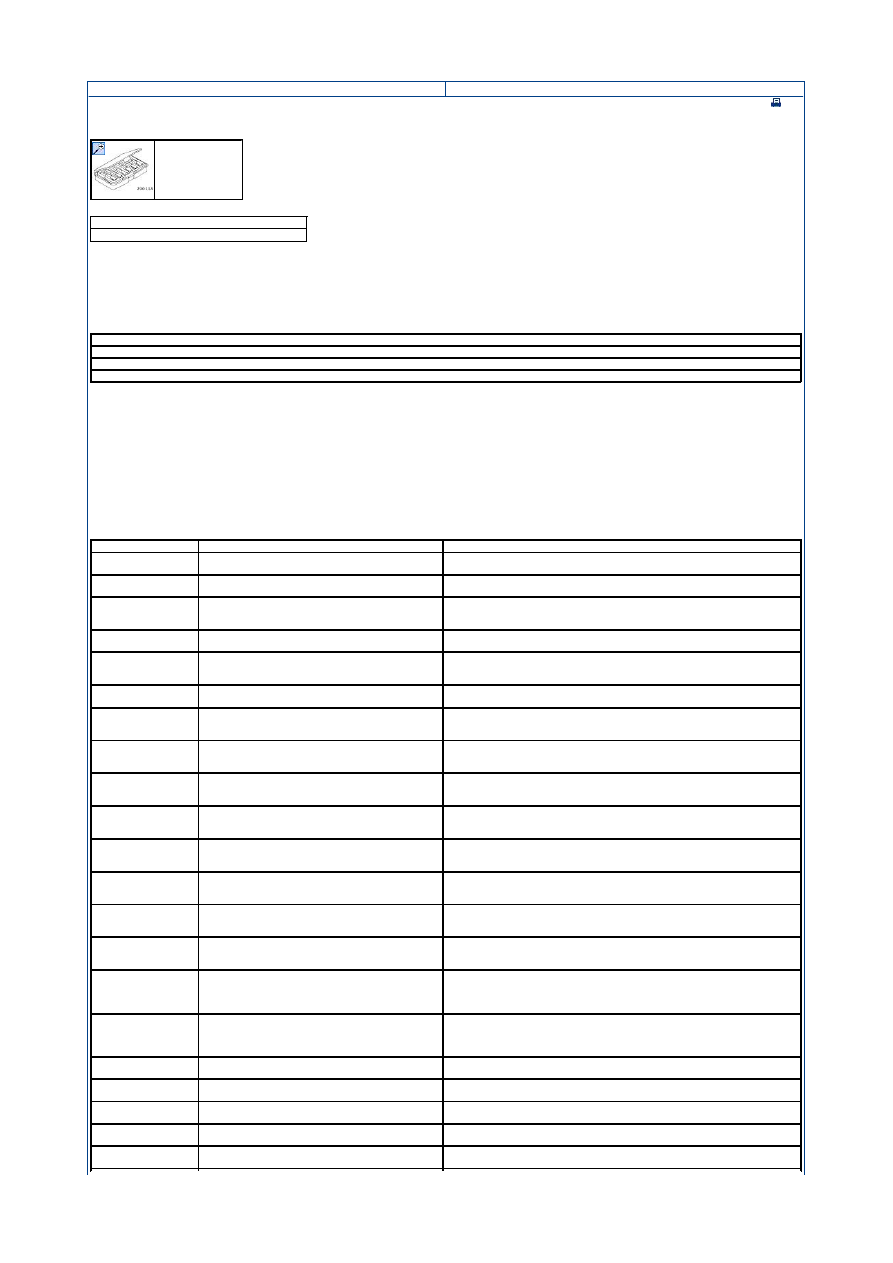
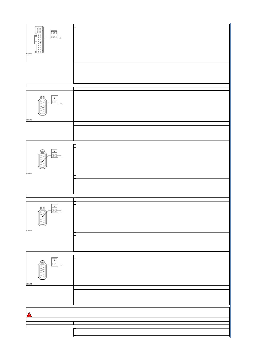
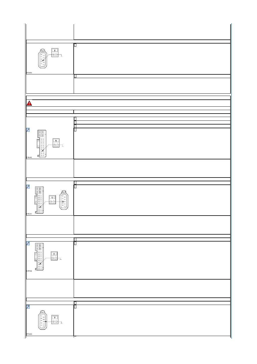
A6: CHECK THE VOLTAGE AT THE DRIVER DOOR MODULE.
Disconnect driver door module C5PL01-A.
1
Measure the voltage between the driver door module connector C5PL01-A pin 2, circuit SBR01A (BK), wiring harness
side and ground.
2
Strona 3 z 16
2012-08-11
http://127.0.0.1:8888/wsm/js/procedure.do?variantId=1449&proc-uid=G927147&gui...

Does the meter display battery voltage?
Yes
CHECK the driver door module and RENEW if necessary. CHECK the operation of the system.
No
LOCATE and RECTIFY the break in the circuit between the driver door module and fuse FA1 (LHD) or fuse FA2 (RHD)
with the aid of the Wiring Diagrams. CHECK the operation of the system.
PINPOINT TEST B : VOLTAGE SUPPLY (TERMINAL 30) AT THE PASSENGER DOOR MODULE FAULTY.
WARNING: The window anti-trap function will not operate during the window motor initialization procedure.
NOTE: If the power to a window regulator motor has been disconnected, it is necessary to initialize that door window motor.
TEST CONDITIONS
DETAILS/RESULTS/ACTIONS
B1: DETERMINE THE VEHICLE VARIANT.
Determine the vehicle variant.
1
Is the vehicle LHD?
Yes
GO to B4
.
No
GO to B2
.
B2: CHECK FUSE FA1
Ignition switch in position 0.
1
CHECK fuse FA1 (RJB).
2
Is the fuse OK?
Yes
GO to B3
.
No
RENEW fuse FA1 (25 A). CHECK the operation of the system. If the fuse blows again, LOCATE and REPAIR the short
using the Wiring Diagrams.
B3: CHECK THE VOLTAGE AT FUSE FA1
Connect fuse FA1 (RJB).
1
Measure the voltage between fuse FA1 (25 A) and ground.
2
Does the meter display battery voltage?
Yes
GO to B6
.
No
REPAIR the voltage supply to fuse FA1 with the aid of the wiring diagrams. CHECK the operation of the system.
B4: CHECK FUSE FA2
CHECK fuse FA2 (RJB).
1
Is the fuse OK?
Yes
GO to B5
.
No
RENEW fuse FA2 (25 A). CHECK the operation of the system. If the fuse blows again, LOCATE and REPAIR the short
using the Wiring Diagrams.
B5: CHECK THE VOLTAGE AT FUSE FA2
Connect fuse FA2 (RJB).
1
Measure the voltage between fuse FA2 (25 A) and ground.
2
Does the meter display battery voltage?
Yes
GO to B6
.
No
REPAIR the voltage supply to fuse FA2 with the aid of the wiring diagrams. CHECK the operation of the system.
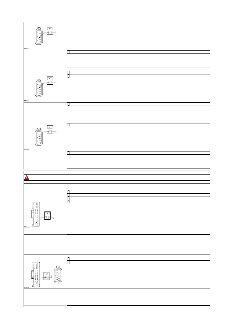
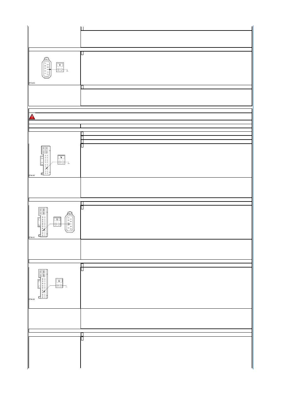
B6: CHECK THE VOLTAGE AT THE PASSENGER DOOR MODULE
Disconnect passenger door module C6PL01-A.
1
Measure the voltage between the passenger door module connector C6PL01-A pin 2, circuit SBR02A (BK), wiring
harness side and ground.
2
Does the meter display battery voltage?
Yes
CHECK the passenger door module and RENEW if necessary. CHECK the operation of the system.
No
LOCATE and RECTIFY the break in the circuit between the passenger door module and fuse FA2 (LHD) or fuse FA1
(RHD) with the aid of the Wiring Diagrams. CHECK the operation of the system.
PINPOINT TEST C : CIRCUIT OF THE PASSENGER CENTRAL LOCKING MOTOR FAULTY.
WARNING: The window anti-trap function will not operate during the window motor initialization procedure.
NOTE: If the power to a window regulator motor has been disconnected, it is necessary to initialize that door window motor.
TEST CONDITIONS
DETAILS/RESULTS/ACTIONS
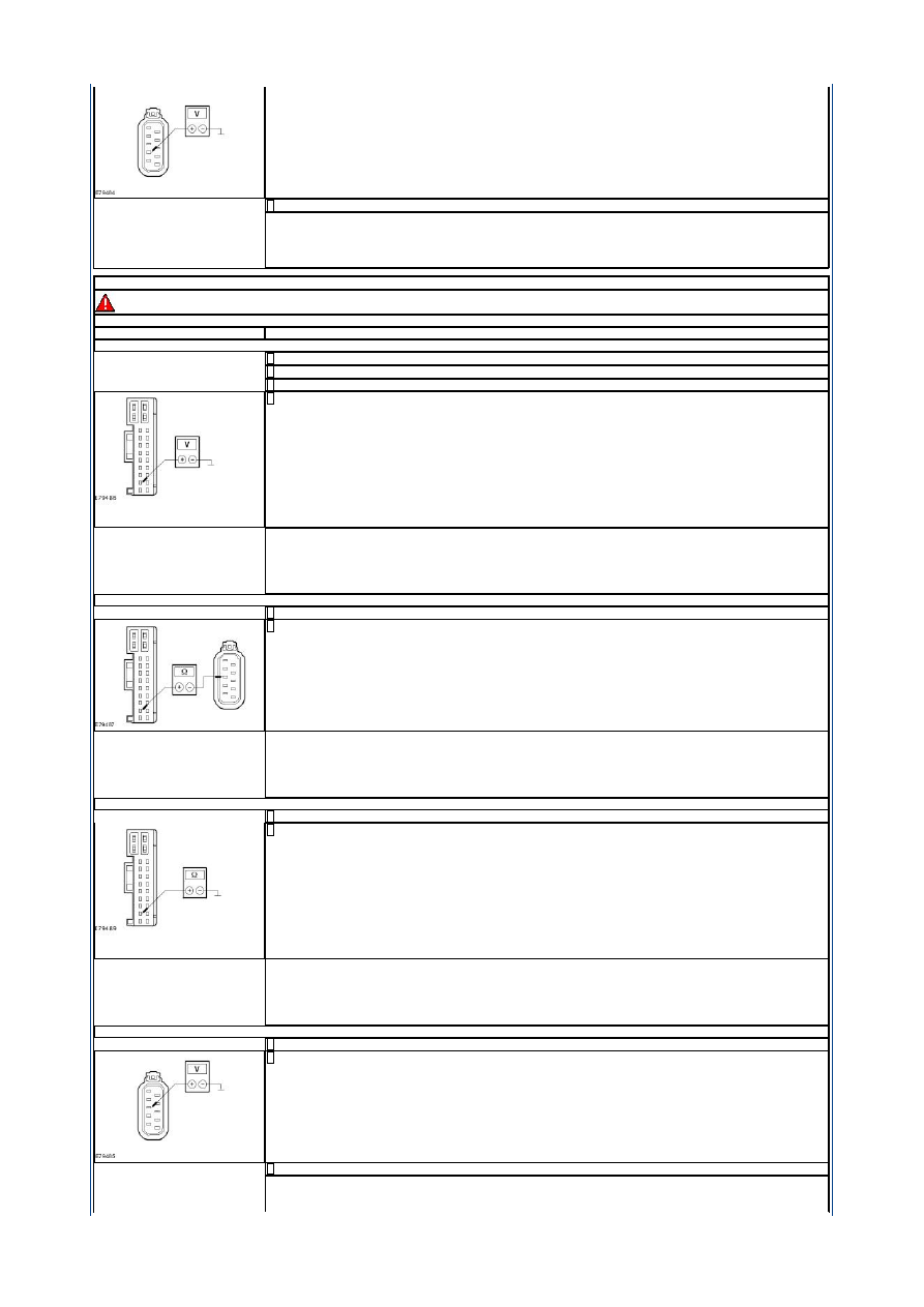
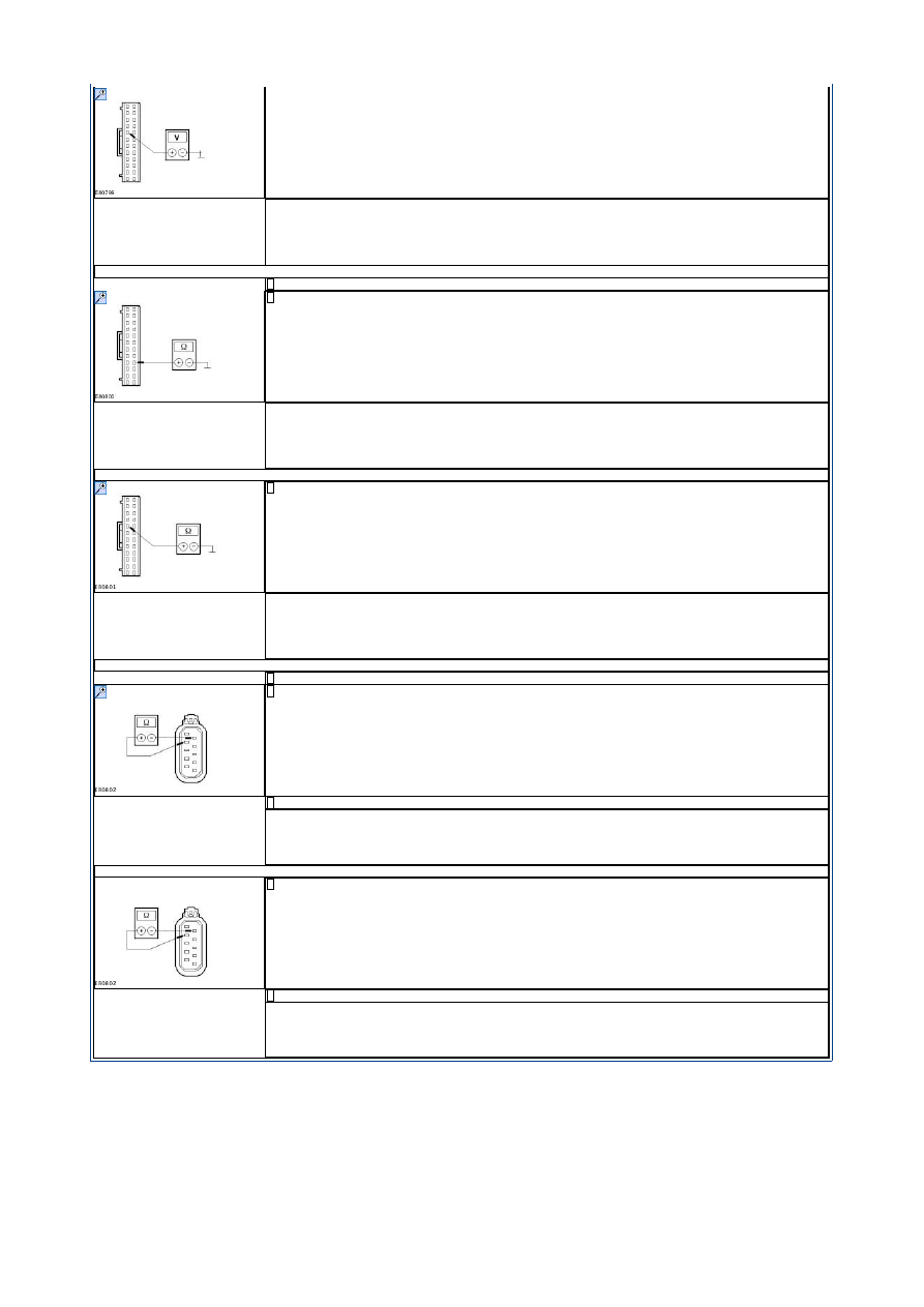
C1: CHECK FOR SHORT TO VOLTAGE IN THE CIRCUIT BETWEEN THE PASSENGER DOOR MODULE AND THE DLC (SCP BUS)
Disconnect passenger door module C6PL01-A.
1
Disconnect passenger door lock C6PL64.
2
Ignition switch in position II.
3
Measure the voltage between:
the passenger door module connector C6PL01-A pin 7, circuit CPL66A (BK), wiring harness side and ground (LHD).
or
the passenger door module connector C6PL01-A pin 7, circuit CPL66AA (BK), wiring harness side and ground (RHD).
4
Is a voltage measured?
Yes
LOCATE and REPAIR the short to voltage in the circuit between the passenger door module and the passenger door lock
with the aid of the Wiring Diagrams. CHECK the operation of the system.
No
LHD vehicles:
GO to C2
.
Strona 4 z 16
2012-08-11
http://127.0.0.1:8888/wsm/js/procedure.do?variantId=1449&proc-uid=G927147&gui...
RHD vehicles:
GO to C3
.
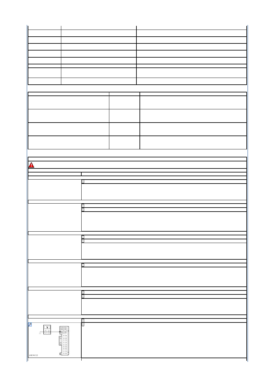
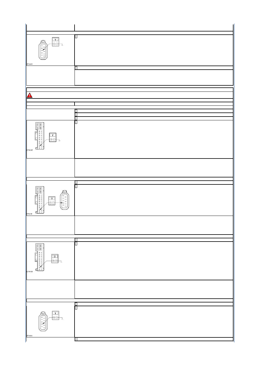
C2: CHECK FOR A BREAK IN THE CIRCUIT BETWEEN THE PASSENGER DOOR MODULE AND THE PASSENGER DOOR LOCK
Ignition switch in position 0.
1
Measure the resistance between the passenger door module connector C6PL01-A, pin 7, circuit CPL66A (BK), wiring
harness side and the passenger door lock connector C6PL64, pin 7, circuit CPL66A (BK), wiring harness side.
2
Is a resistance of less than 2 Ohm measured?
Yes
GO to C4
.
No
LOCATE and REPAIR the break in circuit CPL66A (BK) between the passenger door module and the passenger door lock
with the aid of the Wiring Diagrams. CHECK the operation of the system.
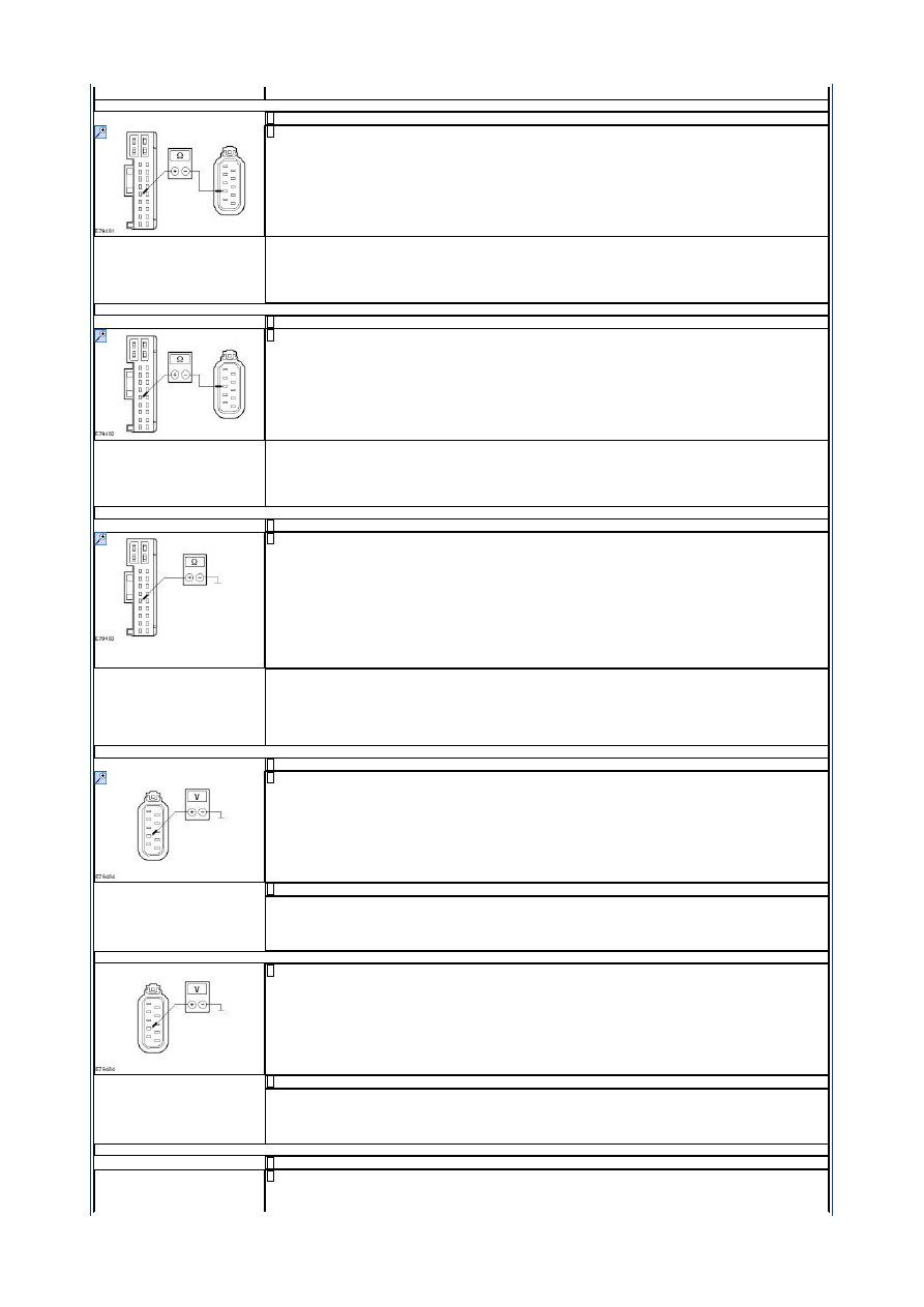
C3: CHECK FOR A BREAK IN THE CIRCUIT BETWEEN THE PASSENGER DOOR MODULE AND THE PASSENGER DOOR LOCK
Ignition switch in position 0.
1
Measure the resistance between the passenger door module connector C6PL01-A pin 7, circuit CPL66AA (BK), wiring
harness side and the passenger door lock connector C6PL64 pin 5, circuit CPL66AA (BK), wiring harness side.
2
Is a resistance of less than 2 Ohm measured?
Yes
GO to C4
.
No
LOCATE and REPAIR the break in circuit CPL66AA (BK) between the passenger door module and the passenger door lock
with the aid of the Wiring Diagrams. CHECK the operation of the system.
C4: CHECK FOR SHORT TO GROUND BETWEEN THE PASSENGER DOOR MODULE AND THE PASSENGER DOOR LOCK
Ignition switch in position 0.
1
Measure the resistance between:
the passenger door module connector C6PL01-A pin 7, circuit CPL66A (BK), wiring harness side and ground (LHD).
or
the passenger door module connector C6PL01-A pin 7, circuit CPL66AA (BK), wiring harness side and ground (RHD).
2
Is a resistance of more than 10,000 ohms measured?
Yes
LHD vehicles:
GO to C5
.
RHD vehicles:
GO to C7
.
No
LOCATE and REPAIR the short to ground in the circuit between the passenger door module and the passenger door lock
with the aid of the Wiring Diagrams. CHECK the operation of the system.
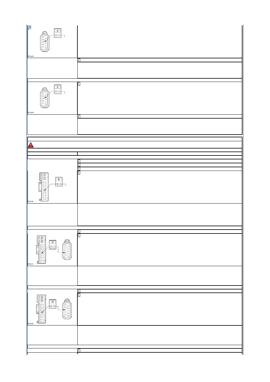
C5: CHECK THE VOLTAGE AT THE PASSENGER DOOR LOCK (DURING LOCKING/UNLOCKING)
Connect passenger door module C6PL01-A.
1
Measure the voltage between the passenger door lock connector C6PL64 pin 7, circuit CPL66A (BK), wiring harness side
and ground.
2
Lock and unlock the vehicle with the key in the door lock cylinder.
3
Is battery voltage measured during unlocking?
Yes
GO to C6
.
No
CHECK and if necessary INSTALL a new passenger door module. CHECK the operation of the system.
C6: CHECK THE VOLTAGE AT THE PASSENGER DOOR LOCK (DURING DOUBLE LOCKING/UNLOCKING)
Measure the voltage between the passenger door lock connector C6PL64 pin 7, circuit CPL66A (BK), wiring harness side
and ground.
1
Double lock and unlock the vehicle with the key in the door lock cylinder.
2
Is battery voltage measured during unlocking?
Yes
CHECK and if necessary INSTALL a new passenger door lock. CHECK the operation of the system.
No
CHECK and if necessary INSTALL a new passenger door module. CHECK the operation of the system.
C7: CHECK THE VOLTAGE AT THE PASSENGER DOOR LOCK (DURING LOCKING/UNLOCKING)
Connect passenger door module C6PL01-A.
1
Measure the voltage between the passenger door lock connector C6PL64 pin 5, circuit CPL66AA (BK), wiring harness
side and ground.
2
Strona 5 z 16
2012-08-11
http://127.0.0.1:8888/wsm/js/procedure.do?variantId=1449&proc-uid=G927147&gui...
Lock and unlock the vehicle with the key in the door lock cylinder.
3
Is battery voltage measured during unlocking?
Yes
GO to C8
.
No
CHECK and if necessary INSTALL a new passenger door module. CHECK the operation of the system.
C8: CHECK THE VOLTAGE AT THE PASSENGER DOOR LOCK (DURING DOUBLE LOCKING/UNLOCKING)
Measure the voltage between the passenger door lock connector C6PL64 pin 5, circuit CPL66AA (BK), wiring harness
side and ground.
1
Double lock and unlock the vehicle with the key in the door lock cylinder.
2
Is battery voltage measured during unlocking?
Yes
CHECK and if necessary INSTALL a new passenger door lock. CHECK the operation of the system.
No
CHECK and if necessary INSTALL a new passenger door module. CHECK the operation of the system.
PINPOINT TEST D : CIRCUIT OF THE DRIVER CENTRAL LOCKING MOTOR FAULTY.
WARNING: The window anti-trap function will not operate during the window motor initialization procedure.
NOTE: If the power to a window regulator motor has been disconnected, it is necessary to initialize that door window motor.
TEST CONDITIONS
DETAILS/RESULTS/ACTIONS
D1: CHECK FOR SHORT TO VOLTAGE BETWEEN THE DRIVER DOOR MODULE AND THE DRIVER DOOR LOCK
Disconnect driver door module C5PL01-A.
1
Disconnect driver door lock C5PL63.
2
Ignition switch in position II.
3
Measure the voltage between:
the driver door module connector C5PL01-A pin 7, circuit CPL51A (BK), wiring harness side and ground (LHD).
or
the driver door module connector C5PL01-A pin 7, circuit CPL51AA (BK), wiring harness side and ground (RHD).
4
Is a voltage measured?
Yes
LOCATE and REPAIR the short to voltage in the circuit between the driver door module and the driver door lock with the
aid of the Wiring Diagrams. CHECK the operation of the system.
No
LHD vehicles:
GO to D3
.
RHD vehicles:
GO to D2
.
D2: CHECK FOR A BREAK IN THE CIRCUIT BETWEEN THE DRIVER DOOR MODULE AND THE DRIVER DOOR LOCK
Ignition switch in position 0.
1
Measure resistance between driver door module connector C5PL01-A pin 7, circuit CPL51AA (BK), wiring harness side
and driver door lock connector C5PL63 pin 7, circuit CPL51AA (BK), wiring harness side.
2
Is a resistance of less than 2 Ohm measured?
Yes
GO to D4
.
No
LOCATE and REPAIR the break in circuit CPL51AA (BK) between the driver door module and the driver door lock with the
aid of the Wiring Diagrams. CHECK the operation of the system.
D3: CHECK FOR A BREAK IN THE CIRCUIT BETWEEN THE DRIVER DOOR MODULE AND THE DRIVER DOOR LOCK
Ignition switch in position 0.
1
Measure the resistance between the driver door module connector C5PL01-A pin 7, circuit CPL51A (BK), wiring harness
side and the driver door lock connector C5PL63 pin 5, circuit CPL51A (BK), wiring harness side.
2
Is a resistance of less than 2 Ohm measured?
Yes
GO to D4
.
No
LOCATE and REPAIR the break in circuit CPL51A (BK) between the driver door module and the driver door lock with the
aid of the Wiring Diagrams. CHECK the operation of the system.
D4: CHECK FOR SHORT TO GROUND BETWEEN THE DRIVER DOOR MODULE AND THE DRIVER DOOR LOCK
Ignition switch in position 0.
1
Strona 6 z 16
2012-08-11
http://127.0.0.1:8888/wsm/js/procedure.do?variantId=1449&proc-uid=G927147&gui...
Measure the resistance between:
the driver door module connector C5PL01-A pin 7, circuit CPL51A (BK), wiring harness side and ground (LHD).
or
the driver door module connector C5PL01-A pin 7, circuit CPL51AA (BK), wiring harness side and ground (RHD).
2
Is a resistance of more than 10,000 ohms measured?
Yes
LHD vehicles:
GO to D7
.
RHD vehicles:
GO to D5
.
No
LOCATE and REPAIR the short to ground in the circuit between the driver door module and the driver door lock with the
aid of the Wiring Diagrams. CHECK the operation of the system.
D5: CHECK THE VOLTAGE AT THE DRIVER DOOR LOCK (DURING LOCKING/UNLOCKING)
Connect driver door module C5PL01-A.
1
Measure the voltage between the driver door lock connector C5PL63 pin 7, circuit CPL51AA (BK), wiring harness side
and ground.
2
Lock and unlock the vehicle with the key in the door lock cylinder.
3
Is battery voltage measured during unlocking?
Yes
GO to D6
.
No
CHECK and if necessary INSTALL a new driver door module. CHECK the operation of the system.
D6: CHECK THE VOLTAGE AT THE DRIVER DOOR LOCK (DURING DOUBLE LOCKING/UNLOCKING)
Measure the voltage between the driver door lock connector C6PL63 pin 7, circuit CPL51AA (BK), wiring harness side
and ground.
1
Double lock and unlock the vehicle with the key in the door lock cylinder.
2
Is battery voltage measured during unlocking?
Yes
CHECK and if necessary INSTALL a new driver door lock. CHECK the operation of the system.
No
CHECK and if necessary INSTALL a new driver door module. CHECK the operation of the system.
D7: CHECK THE VOLTAGE AT THE DRIVER DOOR LOCK (DURING LOCKING/UNLOCKING)
Connect driver door module C5PL01-A.
1
Measure the voltage between the driver door lock connector C5PL63 pin 5, circuit CPL51A (BK), wiring harness side and
ground.
2
Lock and unlock the vehicle with the key in the door lock cylinder.
3
Is battery voltage measured during unlocking?
Yes
GO to D8
.
No
CHECK and if necessary INSTALL a new driver door module. CHECK the operation of the system.
D8: CHECK THE VOLTAGE AT THE DRIVER DOOR LOCK (DURING DOUBLE LOCKING/UNLOCKING)
Measure the voltage between the driver door lock connector C5PL63 pin 5, circuit CPL51A (BK), wiring harness side and
ground.
1
Double lock and unlock the vehicle with the key in the door lock cylinder.
2
Is battery voltage measured during unlocking?
Yes
CHECK and if necessary INSTALL a new driver door lock. CHECK the operation of the system.
No
CHECK and if necessary INSTALL a new driver door module. CHECK the operation of the system.
PINPOINT TEST E : CIRCUIT OF THE DRIVER CENTRAL LOCKING MOTOR WITH DOUBLE LOCKING FAULTY.
WARNING: The window anti-trap function will not operate during the window motor initialization procedure.
NOTE: If the power to a window regulator motor has been disconnected, it is necessary to initialize that door window motor.
TEST CONDITIONS
DETAILS/RESULTS/ACTIONS
E1: CHECK FOR SHORT TO VOLTAGE BETWEEN THE DRIVER DOOR MODULE AND THE DRIVER DOOR LOCK
Disconnect driver door module C5PL01-A.
1
Disconnect driver door lock C5PL63.
2
Strona 7 z 16
2012-08-11
http://127.0.0.1:8888/wsm/js/procedure.do?variantId=1449&proc-uid=G927147&gui...

Ignition switch in position II.
3
Measure the voltage between:
the driver door module connector C5PL01-A pin 10, circuit CPL02A (BK), wiring harness side and ground (LHD).
or
the driver door module connector C5PL01-A pin 10, circuit CPL02AA (BK), wiring harness side and ground (RHD).
4
Is a voltage measured?
Yes
LOCATE and REPAIR the short to voltage in the circuit between the driver door module and the driver door lock with the
aid of the Wiring Diagrams. CHECK the operation of the system.
No
LHD vehicles:
GO to E2
.
RHD vehicles:
GO to E3
.
E2: CHECK FOR A BREAK IN THE CIRCUIT BETWEEN THE DRIVER DOOR MODULE AND THE DRIVER DOOR LOCK
Ignition switch in position 0.
1
Measure the resistance betweenthe driver door module connector C5PL01-A pin 10, circuit CPL02A (BK), wiring harness
side and the driver door lock connector C5PL63 pin 7, circuit CPL02A (BK), wiring harness side.
2
Is a resistance of less than 2 Ohm measured?
Yes
GO to E4
.
No
LOCATE and REPAIR the break in circuit CPL02A (BK) between the driver door module and the driver door lock with the
aid of the Wiring Diagrams. CHECK the operation of the system.
E3: CHECK FOR A BREAK IN THE CIRCUIT BETWEEN THE DRIVER DOOR MODULE AND THE DRIVER DOOR LOCK
Ignition switch in position 0.
1
Measure the resistance between the driver door module connector C5PL01-A pin 10, circuit CPL02AA (BK), wiring
harness side and the driver door lock connector C5PL63 pin 5, circuit CPL02AA (BK), wiring harness side.
2
Is a resistance of less than 2 Ohm measured?
Yes
GO to E4
.
No
LOCATE and REPAIR the break in circuit CPL02AA (BK) between the driver door module and the driver door lock with the
aid of the Wiring Diagrams. CHECK the operation of the system.
E4: CHECK FOR SHORT TO GROUND BETWEEN THE DRIVER DOOR MODULE AND THE DRIVER DOOR LOCK
Measure the resistance between:
the driver door module connector C5PL01-A pin 10, circuit CPL02A (BK), wiring harness side and ground (LHD).
or
the driver door module connector C5PL01-A pin 10, circuit CPL02AA (BK), wiring harness side and ground (RHD).
1
Is a resistance of more than 10,000 ohms measured?
Yes
LHD vehicles:
GO to E5
.
RHD vehicles:
GO to E7
.
No
LOCATE and REPAIR the short to ground in the circuit between the driver door module and the driver door lock with the
aid of the Wiring Diagrams. CHECK the operation of the system.
E5: CHECK THE VOLTAGE AT THE DRIVER DOOR LOCK (DURING LOCKING/UNLOCKING
Connect driver door module C5PL01-A.
1
Measure the voltage between the driver door lock connector C5PL63 pin 7, circuit CPL02A (BK), wiring harness side and
ground.
2
Lock and unlock the vehicle with the key in the door lock cylinder.
3
Is battery voltage measured during unlocking?
Yes
GO to E6
.
No
CHECK and if necessary INSTALL a new driver door module. CHECK the operation of the system.
E6: CHECK THE VOLTAGE AT THE DRIVER DOOR LOCK (DURING DOUBLE LOCKING/UNLOCKING)
Measure the voltage between the driver door lock connector C6PL63 pin 7, circuit CPL02A (BK), wiring harness side and
ground.
1
Strona 8 z 16
2012-08-11
http://127.0.0.1:8888/wsm/js/procedure.do?variantId=1449&proc-uid=G927147&gui...
Double lock and unlock the vehicle with the key in the door lock cylinder.
2
Is battery voltage measured during unlocking?
Yes
CHECK and if necessary INSTALL a new driver door lock. CHECK the operation of the system.
No
CHECK and if necessary INSTALL a new driver door module. CHECK the operation of the system.
E7: CHECK THE VOLTAGE AT THE DRIVER DOOR LOCK (DURING LOCKING/UNLOCKING)
Connect driver door module C5PL01-A.
1
Measure the voltage between the driver door lock connector C5PL63 pin 5, circuit CPL02AA (BK), wiring harness side
and ground.
2
Lock and unlock the vehicle with the key in the door lock cylinder.
3
Is battery voltage measured during unlocking?
Yes
GO to E8
.
No
CHECK and if necessary INSTALL a new driver door module. CHECK the operation of the system.
E8: CHECK THE VOLTAGE AT THE DRIVER DOOR LOCK (DURING DOUBLE LOCKING/UNLOCKING)
Measure the voltage between the driver door lock connector C5PL63 pin 5, circuit CPL02AA (BK), wiring harness side
and ground.
1
Double lock and unlock the vehicle with the key in the door lock cylinder.
2
Is battery voltage measured during unlocking?
Yes
CHECK and if necessary INSTALL a new driver door lock. CHECK the operation of the system.
No
CHECK and if necessary INSTALL a new driver door module. CHECK the operation of the system.
PINPOINT TEST F : CIRCUIT OF THE PASSENGER CENTRAL LOCKING MOTOR WITH DOUBLE LOCKING FAULTY.
WARNING: The window anti-trap function will not operate during the window motor initialization procedure.
NOTE: If the power to a window regulator motor has been disconnected, it is necessary to initialize that door window motor.
TEST CONDITIONS
DETAILS/RESULTS/ACTIONS
F1: CHECK FOR SHORT TO VOLTAGE BETWEEN THE PASSENGER DOOR MODULE AND THE PASSENGER DOOR LOCK
Disconnect passenger door module C6PL01-A.
1
Disconnect passenger door lock C6PL64.
2
Ignition switch in position II.
3
Measure the voltage between:
the passenger door module connector C6PL01-A pin 10, circuit CPL65A (BK), wiring harness side and ground (LHD).
or
the passenger door module connector C6PL01-A pin 10, circuit CPL65AA (BK), wiring harness side and ground (RHD).
4
Is a voltage measured?
Yes
LOCATE and REPAIR the short to voltage in the circuit between the passenger door module and the passenger door lock
with the aid of the Wiring Diagrams. CHECK the operation of the system.
No
LHD vehicles:
GO to F2
.
RHD vehicles:
GO to F3
.
F2: CHECK FOR A BREAK IN THE CIRCUIT BETWEEN THE PASSENGER DOOR MODULE AND THE PASSENGER DOOR LOCK
Ignition switch in position 0.
1
Measure the resistance between the passenger door module connector C6PL01-A pin 10, circuit CPL65A (BK), wiring
harness side and the passenger door lock connector C6PL64 pin 5, circuit CPL65A (BK), wiring harness side.
2
Is a resistance of less than 2 Ohm measured?
Yes
GO to F4
.
No
LOCATE and REPAIR the break in circuit CPL65A (BK) between the passenger door module and the passenger door lock
with the aid of the Wiring Diagrams. CHECK the operation of the system.
Strona 9 z 16
2012-08-11
http://127.0.0.1:8888/wsm/js/procedure.do?variantId=1449&proc-uid=G927147&gui...

F3: CHECK FOR A BREAK IN THE CIRCUIT BETWEEN THE PASSENGER DOOR MODULE AND THE PASSENGER DOOR LOCK
Ignition switch in position 0.
1
Measure the resistance between the passenger door module connector C6PL01-A pin 10, circuit CPL65AA (BK), wiring
harness side and the passenger door lock connector C6PL64 pin 7, circuit CPL65AA (BK), wiring harness side.
2
Is a resistance of less than 2 Ohm measured?
Yes
GO to F4
.
No
LOCATE and REPAIR the break in circuit CPL65AA (BK) between the passenger door module and the passenger door lock
with the aid of the Wiring Diagrams. CHECK the operation of the system.
F4: CHECK FOR SHORT TO GROUND BETWEEN THE PASSENGER DOOR MODULE AND THE PASSENGER DOOR LOCK
Ignition switch in position 0.
1
Measure the resistance between:
the passenger door module connector C6PL01-A, pin 10, circuit CPL65A (BK), wiring harness side and ground.
or
the passenger door module connector C6PL01-A pin 10, circuit CPL65AA (BK), wiring harness side and ground.
2
Is a resistance of more than 10,000 ohms measured?
Yes
LHD vehicles:
GO to F5
.
RHD vehicles:
GO to F7
.
No
LOCATE and REPAIR the short to ground in the circuit between the passenger door module and the passenger door lock
with the aid of the Wiring Diagrams. CHECK the operation of the system.
F5: CHECK THE VOLTAGE AT THE PASSENGER DOOR LOCK (DURING LOCKING/UNLOCKING)
Connect passenger door module C6PL01-A.
1
Measure the voltage between the passenger door lock connector C6PL64 pin 5, circuit CPL65A (BK), wiring harness side
and ground.
2
Lock and unlock the vehicle with the key in the door lock cylinder.
3
Is battery voltage measured during unlocking?
Yes
GO to F6
.
No
CHECK and if necessary INSTALL a new passenger door module. CHECK the operation of the system.
F6: CHECK THE VOLTAGE AT THE PASSENGER DOOR LOCK (DURING DOUBLE LOCKING/UNLOCKING)
Measure the voltage between the passenger door lock connector C6PL64 pin 5, circuit CPL65A (BK), wiring harness side
and ground.
1
Double lock and unlock the vehicle with the key in the door lock cylinder.
2
Is battery voltage measured during unlocking?
Yes
CHECK and if necessary INSTALL a new passenger door lock. CHECK the operation of the system.
No
CHECK and if necessary INSTALL a new passenger door module. CHECK the operation of the system.
F7: CHECK THE VOLTAGE AT THE PASSENGER DOOR LOCK (DURING DOUBLE LOCKING/UNLOCKING)
Connect passenger door module C6PL01-A.
1
Measure the voltage between the passenger door lock connector C6PL64 pin 7, circuit CPL66A (BK), wiring harness side
and ground.
2
Double lock and unlock the vehicle with the key in the door lock cylinder.
3
Is battery voltage measured during unlocking?
Yes
GO to F8
.
No
CHECK and if necessary INSTALL a new passenger door module. CHECK the operation of the system.
F8: CHECK THE VOLTAGE AT THE PASSENGER DOOR LOCK (DURING LOCKING/UNLOCKING)
Measure the voltage between the passenger door lock connector C6PL64 pin 7, circuit CPL66A (BK), wiring harness side
and ground.
1
Strona 10 z 16
2012-08-11
http://127.0.0.1:8888/wsm/js/procedure.do?variantId=1449&proc-uid=G927147&gui...
Lock and unlock the vehicle with the key in the door lock cylinder.
2
Is battery voltage measured during unlocking?
Yes
CHECK and if necessary INSTALL a new passenger door lock. CHECK the operation of the system.
No
CHECK and if necessary INSTALL a new passenger door module. CHECK the operation of the system.
PINPOINT TEST G : CIRCUIT OF THE RIGHT REAR CENTRAL LOCKING MOTOR FAULTY.
WARNING: The window anti-trap function will not operate during the window motor initialization procedure.
NOTE: If the power to a window regulator motor has been disconnected, it is necessary to initialize that door window motor.
TEST CONDITIONS
DETAILS/RESULTS/ACTIONS
G1: CHECK FOR SHORT TO VOLTAGE BETWEEN THE RIGHT REAR DOOR MODULE AND THE RIGHT REAR DOOR LOCK
Disconnect right rear door module C8PL01.
1
Disconnect right rear door lock C8PL72.
2
Ignition switch in position II.
3
Measure the voltage between the right rear door module connector C8PL01 pin 10, circuit CPL11A (BK), wiring harness
side and ground.
4
Is a voltage measured?
Yes
LOCATE and REPAIR the short to voltage in circuit CPL11A (BK) between the right rear door module and the right rear
door lock with the aid of the Wiring Diagrams. CHECK the operation of the system.
No
GO to G2
.
G2: CHECK FOR A BREAK IN THE CIRCUIT BETWEEN THE RIGHT REAR DOOR MODULE AND THE RIGHT REAR DOOR LOCK
Ignition switch in position 0.
1
Measure the resistance between the right rear door module connector C8PL01 pin 10, circuit CPL11A (BK), wiring
harness side and the right rear door lock connector C8PL72 pin 5, circuit CPL11A (BK), wiring harness side.
2
Is a resistance of less than 2 Ohm measured?
Yes
GO to G3
.
No
LOCATE and REPAIR the break in circuit CPL11A (BK) between the right rear door module and the right rear door lock
with the aid of the Wiring Diagrams. CHECK the operation of the system.
G3: CHECK FOR SHORT TO GROUND IN THE CIRCUIT BETWEEN THE RIGHT REAR DOOR MODULE AND THE RIGHT REAR DOOR LOCK
Ignition switch in position 0.
1
Measure the resistance between the right rear door module connector C8PL01 pin 10, circuit CPL11A (BK), wiring
harness side and ground.
2
Is a resistance of more than 10,000 ohms measured?
Yes
GO to G4
.
No
LOCATE and REPAIR the short to ground in circuit CPL11A (BK) between the right rear door module and the right rear
door lock with the aid of the Wiring Diagrams. CHECK the operation of the system.
G4: CHECK THE VOLTAGE AT THE RIGHT REAR DOOR LOCK (DURING LOCKING/UNLOCKING)
Connect right rear door module C8PL01.
1
Measure the voltage between the right rear door lock connector C8PL72 pin 5, circuit CPL11A (BK), wiring harness side
and ground.
2
Lock and unlock the vehicle with the key in the door lock cylinder.
3
Is battery voltage measured during unlocking?
Yes
GO to G5
.
Strona 11 z 16
2012-08-11
http://127.0.0.1:8888/wsm/js/procedure.do?variantId=1449&proc-uid=G927147&gui...
No
CHECK and if necessary INSTALL a new right rear door module. CHECK the operation of the system.
G5: CHECK THE VOLTAGE AT THE RIGHT REAR DOOR LOCK (DURING DOUBLE LOCKING/UNLOCKING)
Measure the voltage between the right rear door lock connector C8PL72 pin 5, circuit CPL11A (BK), wiring harness side
and ground.
1
Double lock and unlock the vehicle with the key in the door lock cylinder.
2
Is battery voltage measured during unlocking?
Yes
CHECK and if necessary INSTALL a new right rear door lock. CHECK the operation of the system.
No
CHECK and if necessary INSTALL a new right rear door module. CHECK the operation of the system.
PINPOINT TEST H : CIRCUIT OF THE LEFT REAR CENTRAL LOCKING MOTOR FAULTY.
WARNING: The window anti-trap function will not operate during the window motor initialization procedure.
NOTE: If the power to a window regulator motor has been disconnected, it is necessary to initialize that door window motor.
TEST CONDITIONS
DETAILS/RESULTS/ACTIONS
H1: CHECK FOR SHORT TO VOLTAGE BETWEEN THE LEFT REAR DOOR MODULE AND THE LEFT REAR DOOR LOCK
Disconnect left rear door module C7PL01.
1
Disconnect left rear door lock C7PL71.
2
Ignition switch in position II.
3
Measure the voltage between the left rear door module connector C7PL01 pin 10, circuit CPL04A (BK), wiring harness
side and ground.
4
Is a voltage measured?
Yes
LOCATE and REPAIR the short to voltage in circuit CPL04A (BK) between the left rear door module and the left door lock
with the aid of the Wiring Diagrams. CHECK the operation of the system.
No
GO to H2
.
H2: CHECK FOR A BREAK IN THE CIRCUIT BETWEEN THE LEFT REAR DOOR MODULE AND THE LEFT REAR DOOR LOCK
Ignition switch in position 0.
1
Measure the resistance between the left rear door module connector C7PL01 pin 10, circuit CPL04A (BK), wiring harness
side and the left rear door lock connector C7PL71 pin 7, circuit CPL04A (BK), wiring harness side.
2
Is a resistance of less than 2 Ohm measured?
Yes
GO to H3
.
No
LOCATE and REPAIR the break in circuit CPL04A (BK) between the left rear door module and the left rear door lock with
the aid of the Wiring Diagrams. CHECK the operation of the system.
H3: CHECK FOR SHORT TO GROUND BETWEEN THE LEFT REAR DOOR MODULE AND THE LEFT REAR DOOR LOCK
Ignition switch in position 0.
1
Measure the resistance between the left rear door module connector C7PL01 pin 10, circuit CPL04A (BK), wiring harness
side and ground.
2
Is a resistance of more than 10,000 ohms measured?
Yes
GO to H4
.
No
LOCATE and REPAIR the short to ground in circuit CPL04A (BK) between the left rear door module and the left rear door
lock with the aid of the Wiring Diagrams. CHECK the operation of the system.
H4: CHECK THE VOLTAGE AT THE LEFT REAR DOOR LOCK (DURING LOCKING/UNLOCKING)
Connect left rear door module C7PL01.
1
Measure the voltage between the left rear door lock connector C7PL71 pin 7, circuit CPL04A (BK), wiring harness side
and ground.
2
Lock and unlock the vehicle with the key in the door lock cylinder.
3
Strona 12 z 16
2012-08-11
http://127.0.0.1:8888/wsm/js/procedure.do?variantId=1449&proc-uid=G927147&gui...
Is battery voltage measured during unlocking?
Yes
GO to H5
.
No
CHECK and if necessary INSTALL a new left rear door module. CHECK the operation of the system.
H5: CHECK THE VOLTAGE AT THE LEFT REAR DOOR LOCK (DURING DOUBLE LOCKING/UNLOCKING)
Measure the voltage between the left rear door lock connector C7PL71 pin 7, circuit CPL04A (BK), wiring harness side
and ground.
1
Double lock and unlock the vehicle with the key in the door lock cylinder.
2
Is battery voltage measured during unlocking?
Yes
CHECK and if necessary INSTALL a new left rear door lock. CHECK the operation of the system.
No
CHECK and if necessary INSTALL a new left rear door lock. CHECK the operation of the system.
PINPOINT TEST I : CIRCUIT OF THE LEFT REAR CENTRAL LOCKING MOTOR WITH DOUBLE LOCKING FAULTY.
WARNING: The window anti-trap function will not operate during the window motor initialization procedure.
NOTE: If the power to a window regulator motor has been disconnected, it is necessary to initialize that door window motor.
TEST CONDITIONS
DETAILS/RESULTS/ACTIONS
I1: CHECK FOR SHORT TO VOLTAGE BETWEEN THE LEFT REAR DOOR MODULE AND THE LEFT REAR DOOR LOCK
Disconnect left rear door module C7PL01.
1
Disconnect left rear door lock C7PL71.
2
Ignition switch in position II.
3
Measure the voltage between the left rear door module connector C7PL01 pin 9, circuit CPL08A (BK), wiring harness
side and ground.
4
Is a voltage measured?
Yes
LOCATE and REPAIR the short to voltage in circuit CPL08A (BK) between the left rear door module and the left door lock
with the aid of the Wiring Diagrams. CHECK the operation of the system.
No
GO to I2
.
I2: CHECK FOR A BREAK IN THE CIRCUIT BETWEEN THE LEFT REAR DOOR MODULE AND THE LEFT REAR DOOR LOCK
Ignition switch in position 0.
1
Measure the resistance between the left rear door module connector C7PL01 pin 9, circuit CPL08A (BK), wiring harness
side and the left rear door lock, connector C7PL71, pin 6, circuit CPL08A (BK), wiring harness side.
2
Is a resistance of less than 2 Ohm measured?
Yes
GO to I3
.
No
LOCATE and REPAIR the break in circuit CPL08A (BK) between the left rear door module and the left rear door lock with
the aid of the Wiring Diagrams. CHECK the operation of the system.
I3: CHECK FOR SHORT TO GROUND BETWEEN THE LEFT REAR DOOR MODULE AND THE LEFT REAR DOOR LOCK (DURING LOCKING/UNLOCKING)
Ignition switch in position 0.
1
Measure the resistance between the left rear door module connector C7PL01 pin 9, circuit CPL08A (BK), wiring harness
side and ground.
2
Is a resistance of more than 10,000 ohms measured?
Yes
GO to I4
.
No
LOCATE and REPAIR the short to ground in circuit CPL08A (BK) between the left rear door module and the left rear door
lock with the aid of the Wiring Diagrams. CHECK the operation of the system.
I4: CHECK THE VOLTAGE AT THE LEFT REAR DOOR LOCK (DURING LOCKING/UNLOCKING)
Connect left rear door module C7PL01.
1
Measure the voltage between the left rear door lock connector C7PL71 pin 6, circuit CPL08A (BK), wiring harness side
and ground.
2
Strona 13 z 16
2012-08-11
http://127.0.0.1:8888/wsm/js/procedure.do?variantId=1449&proc-uid=G927147&gui...
Lock and unlock the vehicle with the key in the door lock cylinder.
3
Is battery voltage measured during unlocking?
Yes
GO to I5
.
No
CHECK and if necessary INSTALL a new left rear door module. CHECK the operation of the system.
I5: CHECK THE VOLTAGE AT THE LEFT REAR DOOR LOCK (DURING DOUBLE LOCKING/UNLOCKING)
Measure the voltage between the left rear door lock connector C7PL71 pin 6, circuit CPL08A (BK), wiring harness side
and ground.
1
Double lock and unlock the vehicle with the key in the door lock cylinder.
2
Is battery voltage measured during unlocking?
Yes
CHECK and if necessary INSTALL a new left rear door lock. CHECK the operation of the system.
No
CHECK and if necessary INSTALL a new left rear door lock. CHECK the operation of the system.
PINPOINT TEST J : CIRCUIT OF THE RIGHT REAR CENTRAL LOCKING MOTOR WITH DOUBLE LOCKING FAULTY.
WARNING: The window anti-trap function will not operate during the window motor initialization procedure.
NOTE: If the power to a window regulator motor has been disconnected, it is necessary to initialize that door window motor.
TEST CONDITIONS
DETAILS/RESULTS/ACTIONS
J1: CHECK FOR SHORT TO VOLTAGE BETWEEN THE RIGHT REAR DOOR MODULE AND THE RIGHT REAR DOOR LOCK
Disconnect right rear door module C8PL01.
1
Disconnect right rear door lock C8PL72.
2
Ignition switch in position II.
3
Measure the voltage between the right rear door module connector C8PL01 pin 9, circuit CPL12A (BK), wiring harness
side and ground.
4
Is a voltage measured?
Yes
LOCATE and REPAIR the short to voltage in circuit CPL12A (BK) between the right rear door module and the right rear
door lock with the aid of the Wiring Diagrams. CHECK the operation of the system.
No
GO to J2
.
J2: CHECK FOR A BREAK IN THE CIRCUIT BETWEEN THE RIGHT REAR DOOR MODULE AND THE RIGHT REAR DOOR LOCK
Ignition switch in position 0.
1
Measure the resistance between the right rear door module connector C8PL01 pin 9, circuit CPL12A (BK), wiring
harness side and the right rear door lock connector C8PL72 pin 6, circuit CPL12A (BK), wiring harness side.
2
Is a resistance of less than 2 Ohm measured?
Yes
GO to J3
.
No
LOCATE and REPAIR the break in circuit CPL12A (BK) between the right rear door module and the right rear door lock
with the aid of the Wiring Diagrams. CHECK the operation of the system.
J3: CHECK FOR SHORT TO GROUND IN THE CIRCUIT BETWEEN THE RIGHT REAR DOOR MODULE AND THE RIGHT REAR DOOR LOCK
Ignition switch in position 0.
1
Measure the resistance between the right rear door module connector C8PL01 pin 9, circuit CPL12A (BK), wiring
harness side and ground.
2
Is a resistance of more than 10,000 ohms measured?
Yes
GO to J4
.
No
LOCATE and REPAIR the short to ground in circuit CPL12A (BK) between the right rear door module and the right rear
door lock with the aid of the Wiring Diagrams. CHECK the operation of the system.
J4: CHECK THE VOLTAGE AT THE RIGHT REAR DOOR LOCK (DURING LOCKING/UNLOCKING)
Connect right rear door module C8PL01.
1
Measure the voltage between the right rear door lock connector C8PL72 pin 6, circuit CPL12A (BK), wiring harness side
and ground.
2
Strona 14 z 16
2012-08-11
http://127.0.0.1:8888/wsm/js/procedure.do?variantId=1449&proc-uid=G927147&gui...

Lock and unlock the vehicle with the key in the door lock cylinder.
3
Is battery voltage measured during unlocking?
Yes
GO to J5
.
No
CHECK and if necessary INSTALL a new right rear door module. CHECK the operation of the system.
J5: CHECK THE VOLTAGE AT THE RIGHT REAR DOOR LOCK (DURING DOUBLE LOCKING/UNLOCKING)
Measure the voltage between the right rear door lock connector C8PL72 pin 6, circuit CPL12A (BK), wiring harness side
and ground.
1
Double lock and unlock the vehicle with the key in the door lock cylinder.
2
Is battery voltage measured during unlocking?
Yes
CHECK and if necessary INSTALL a new right rear door lock. CHECK the operation of the system.
No
CHECK and if necessary INSTALL a new right rear door lock. CHECK the operation of the system.
PINPOINT TEST K : CIRCUIT OF THE PASSENGER COMPARTMENT LOCKING SWITCH FAULTY.
WARNING: The window anti-trap function will not operate during the window motor initialization procedure.
NOTE: If the power to a window regulator motor has been disconnected, it is necessary to initialize that door window motor.
TEST CONDITIONS
DETAILS/RESULTS/ACTIONS
K1: CHECK FOR A BREAK IN THE CIRCUIT BETWEEN THE DRIVER DOOR MODULE AND THE DRIVER DOOR LOCK
Ignition switch in position 0.
1
Disconnect driver door module C5PL01-B.
2
Disconnect driver door lock C5PL63.
3
Measure the resistance between the driver door module connector C5PL01-B pin 21, circuit CPL42A (BK), wiring
harness side and the driver door lock connector C5PL63 pin 2, circuit CPL42A (BK), wiring harness side.
4
Is a resistance of less than 2 Ohm measured?
Yes
GO to K2
.
No
LOCATE and REPAIR the break in circuit CPL42A (BK) between the driver door module and the driver door lock with the
aid of the Wiring Diagrams. CHECK the operation of the system.
K2: CHECK FOR A BREAK IN THE CIRCUIT BETWEEN THE DRIVER DOOR MODULE AND THE DRIVER DOOR LOCK
Measure the resistance between the driver door module connector C5PL01-B pin 5, circuit CPL43A (BK), wiring harness
side and the driver door lock connector C5PL63 pin 3, circuit CPL43A (BK), wiring harness side.
1
Is a resistance of less than 2 Ohm measured?
Yes
GO to K3
.
No
LOCATE and REPAIR the break in circuit CPL43A (BK) between the driver door module and the driver door lock with the
aid of the Wiring Diagrams. CHECK the operation of the system.
K3: CHECK FOR SHORT TO VOLTAGE BETWEEN THE DRIVER DOOR MODULE AND THE DRIVER DOOR LOCK
Ignition switch in position II.
1
Measure the voltage between the driver door module connector C5PL01-B pin 21, circuit CPL42A (BK), wiring harness
side and ground.
2
Is a voltage measured?
Yes
LOCATE and REPAIR the short to voltage in circuit CPL42A (BK) between the driver door module and the driver door lock
with the aid of the Wiring Diagrams. CHECK the operation of the system.
No
GO to K4
.
K4: CHECK FOR SHORT TO VOLTAGE BETWEEN THE DRIVER DOOR MODULE AND THE DRIVER DOOR LOCK
Measure the voltage between the driver door module connector C5PL01-B pin 5, circuit CPL43A (BK), wiring harness
side and ground.
1
Strona 15 z 16
2012-08-11
http://127.0.0.1:8888/wsm/js/procedure.do?variantId=1449&proc-uid=G927147&gui...
Is a voltage measured?
Yes
LOCATE and REPAIR the short to voltage in circuit CPL43A (BK) between the driver door module and the driver door lock
with the aid of the Wiring Diagrams. CHECK the operation of the system.
No
GO to K5
.
K5: CHECK FOR SHORT TO GROUND BETWEEN THE DRIVER DOOR MODULE AND THE DRIVER DOOR LOCK
Ignition switch in position 0.
1
Measure the resistance between the driver door module connector C5PL01-B pin 21, circuit CPL42A (BK), wiring
harness side and ground.
2
Is a resistance of more than 10,000 ohms measured?
Yes
GO to K6
.
No
LOCATE and REPAIR the short to ground in circuit CPL42A (BK) between the driver door module and the driver door lock
with the aid of the Wiring Diagrams. CHECK the operation of the system.
K6: CHECK FOR SHORT TO GROUND BETWEEN THE DRIVER DOOR MODULE AND THE DRIVER DOOR LOCK
Measure the resistance between the driver door module connector C5PL01-B pin 5, circuit CPL43A (BK), wiring harness
side and ground.
1
Is a resistance of more than 10,000 ohms measured?
Yes
GO to K7
.
No
LOCATE and REPAIR the short to ground in circuit CPL43A (BK) between the driver door module and the driver door lock
with the aid of the Wiring Diagrams. CHECK the operation of the system.
K7: CHECK THE VOLTAGE AT THE DRIVER DOOR LOCK (DURING LOCKING)
Connect driver door module C5PL01-B.
1
Measure the voltage between the driver door lock connector C5PL63 pin 3, circuit CPL43A (BK), wiring harness side and
the driver door lock connector C5PL63 pin 2, circuit CPL42A (BK), wiring harness side.
2
Lock the vehicle using the passenger compartment locking switch.
3
Is a voltage of more than 3.5 V measured?
Yes
GO to K8
.
No
CHECK and if necessary INSTALL a new driver door module. CHECK the operation of the system.
K8: CHECK THE VOLTAGE AT THE DRIVER DOOR LOCK (DURING UNLOCKING)
Measure the voltage between the driver door lock connector C5PL63 pin 3, circuit CPL43A (BK), wiring harness side and
the driver door lock connector C5PL63 pin 2, circuit CPL42A (BK), wiring harness side.
1
Unlock the vehicle using the passenger compartment locking switch.
2
Is a voltage of less than 1.5 V measured?
Yes
CHECK and if necessary INSTALL a new driver door lock. CHECK the operation of the system.
No
CHECK and if necessary INSTALL a new driver door module. CHECK the operation of the system.
Strona 16 z 16
2012-08-11
http://127.0.0.1:8888/wsm/js/procedure.do?variantId=1449&proc-uid=G927147&gui...
Wyszukiwarka
Podobne podstrony:
Diagnozowanie sterowania pracą silnika Daewoo Matiz
Diagnostyka sterownika S7 – 300 Część 1 – wykrywanie błędów systemowych
Diagnostyka i sterowanie silników spalinowych sciaga
kodowanie sterownikow Audi A4, auta, Diagnostyka dokumety, procedury diagnostyczne
Diagnozowanie układów sterowania silnikami w samochodach Lanos cz 1 pdf
Ćw 6 ZASTOSOWANIE STEROWNIKA PLC W KOMPUTEROWYCH SYSTEMACH POMIAROWO DIAGNOSTYCZNYCH
Sterowanie napełnianiem, !! DIAGNOSTYKA SAMOCHODOWA, ukłądy wtryskowe
Dopasowanie pilotów zdalnego sterowania, auta, Diagnostyka dokumety, procedury diagnostyczne
kodowanie sterownikow Audi A4, auta, Diagnostyka dokumety, procedury diagnostyczne
Elektrycznie sterowane szyby przednich drzwi
Opis sterowania i diagnostyki EN57 asyn
sterowanie podcisnieniem i turbo vnt diagnostyka
opis czujników, sterowników, usterki diagnoz Ford Mondeo
diagnostyka
T 3[1] METODY DIAGNOZOWANIA I ROZWIAZYWANIA PROBLEMOW
Przedmiot PRI i jego diagnoza przegląd koncepcji temperamentu
więcej podobnych podstron