Air-Conditioners
PLA-RP·AA
English
Deutsch
Français
Nederlands
Español
Italiano
∂ÏÏËÓÈο
Português
Dansk
Svenska
Türkçe
Русский
INSTALLATION MANUAL
For safe and correct use, please read this installation manual thoroughly before installing the air-conditioner
unit.
INSTALLATIONSHANDBUCH
Zum sicheren und ordnungsgemäßen Gebrauch der Klimaanlage das Installationshandbuch gründlich
durchlesen.
MANUEL D’INSTALLATION
Veuillez lire le manuel d’installation en entier avant d’installer ce climatiseur pour éviter tout accident et vous
assurer d’une utilisation correcte.
INSTALLATIONSMANUAL
Läs denna installationsmanual noga för säkert och korrekt bruk innan luftkonditioneringen installeras.
INSTALLATIEHANDLEIDING
Voor een veilig en juist gebruik moet u deze installatiehandleiding grondig doorlezen voordat u de airconditioner
installeert.
MANUALE DI INSTALLAZIONE
Per un uso sicuro e corretto, leggere attentamente questo manuale di installazione prima di installare il condizionatore
d’aria.
MANUAL DE INSTALACIÓN
Para un uso seguro y correcto, lea detalladamente este manual de instalación antes de montar la unidad de
aire acondicionado.
E°XEIPI¢IO O¢H°IøN E°KATA™TA™H™
°È· ·ÛÊ¿ÏÂÈ· Î·È ÛˆÛÙ‹ ¯Ú‹ÛË, ·Ú·Î·Ï›ÛÙ ‰È·‚¿ÛÂÙ ÚÔÛ¯ÙÈο ·˘Ùfi ÙÔ ÂÁ¯ÂÈÚ›‰ÈÔ ÂÁηٿÛÙ·Û˘
ÚÈÓ ·Ú¯›ÛÂÙ ÙËÓ ÂÁηٿÛÙ·ÛË Ù˘ ÌÔÓ¿‰·˜ ÎÏÈÌ·ÙÈÛÌÔ‡.
MANUAL DE INSTALAÇÃO
Para segurança e utilização correctas, leia atentamente este manual de instalação antes de instalar a unidade
de ar condicionado.
INSTALLATIONSMANUAL
Læs venligst denne installationsmanual grundigt, før De installerer airconditionanlægget, af hensyn til sikker og
korrekt anvendelse.
MONTAJ ELK‹TABI
Emniyetli ve do¤ru biçimde nas›l kullan›laca¤›n› ö¤renmek için lütfen klima cihaz›n› monte etmeden önce bu
elkitab›n› dikkatle okuyunuz.
РУКОВОДСТВО ПО УСТАНОВКЕ
Для осторожного и правильного использования прибора необходимо тщательно ознакомиться с данным
руководством по установке до выполнения установки кондиционера.
FOR INSTALLER
FÜR INSTALLATEURE
POUR L’INSTALLATEUR
FÖR INSTALLATÖREN
VOOR DE INSTALLATEUR
PER L’INSTALLATORE
PARA EL INSTALADOR
PARA O INSTALADOR
TIL INSTALLATØREN
°π∞ ∞À∆√¡ ¶√À ∫∞¡∂π ∆∏¡ ∂°∫∞∆∞™∆∞™∏
MONTÖR ‹Ç‹N
ДЛЯ УСТАНОВИТЕЛЯ
2
s Before installing the unit, make sure you read all the “Safety precau-
tions”.
s Please report to your supply authority or obtain their consent before
connecting this equipment to the power supply system.
Warning:
Describes precautions that must be observed to prevent danger of injury or
death to the user.
Caution:
Describes precautions that must be observed to prevent damage to the unit.
After installation work has been completed, explain the “Safety Precautions,” use,
and maintenance of the unit to the customer according to the information in the Op-
eration Manual and perform the test run to ensure normal operation. Both the Instal-
lation Manual and Operation Manual must be given to the user for keeping. These
manuals must be passed on to subsequent users.
1.2. Before installation or relocation
Caution:
• Be extremely careful when transporting the units. Two or more persons are
needed to handle the unit, as it weighs 20 kg or more. Do not grasp the
packaging bands. Wear protective gloves as you can injure your hands on
the fins or other parts.
• Be sure to safely dispose of the packaging materials. Packaging materials,
such as nails and other metal or wooden parts may cause stabs or other
injuries.
Contents
Warning:
• Ask a dealer or an authorized technician to install the unit.
• For installation work, follow the instructions in the Installation Manual and use
tools and pipe components specifically made for use with refrigerant specified
in the outdoor unit installation manual.
• The unit must be installed according to the instructions in order to minimize
the risk of damage from earthquakes, typhoons, or strong winds. An incor-
rectly installed unit may fall down and cause damage or injuries.
• The unit must be securely installed on a structure that can sustain its weight.
• If the air conditioner is installed in a small room, measures must be taken to
prevent the refrigerant concentration in the room from exceeding the safety
limit in the event of refrigerant leakage. Should the refrigerant leak and cause
the concentration limit to be exceeded, hazards due to lack of oxygen in the
room may result.
• Ventilate the room if refrigerant leaks during operation. If refrigerant comes
into contact with a flame, poisonous gases will be released.
• All electric work must be performed by a qualified technician according to
local regulations and the instructions given in this manual.
• Use only specified cables for wiring.
• The terminal block cover panel of the unit must be firmly attached.
• Use only accessories authorized by Mitsubishi Electric and ask a dealer or
an authorized technician to install them.
• The user should never attempt to repair the unit or transfer it to another loca-
tion.
• After installation has been completed, check for refrigerant leaks. If refriger-
ant leaks into the room and comes into contact with the flame of a heater or
portable cooking range, poisonous gases will be released.
1.1. Before installation (Euvironment)
Caution:
• Do not use the unit in an unusual environment. If the air conditioner is in-
stalled in areas exposed to steam, volatile oil (including machine oil), or sulfuric
gas, areas exposed to high salt content such as the seaside, the performance
can be significantly reduced and the internal parts can be damaged.
• Do not install the unit where combustible gases may leak, be produced, flow,
or accumulate. If combustible gas accumulates around the unit, fire or explo-
sion may result.
• Do not keep food, plants, caged pets, artwork, or precision instruments in the
direct airflow of the indoor unit or too close to the unit, as these items can be
damaged by temperature changes or dripping water.
• When the room humidity exceeds 80% or when the drainpipe is clogged, wa-
ter may drip from the indoor unit. Do not install the indoor unit where such
dripping can cause damage.
• When installing the unit in a hospital or communications office, be prepared
for noise and electronic interference. Inverters, home appliances, high-fre-
quency medical equipment, and radio communications equipment can cause
the air conditioner to malfunction or breakdown. The air conditioner may also
affect medical equipment, disturbing medical care, and communications equip-
ment, harming the screen display quality.
• Thermal insulation of the refrigerant pipe is necessary to prevent condensa-
tion. If the refrigerant pipe is not properly insulated, condensation will be formed.
• Place thermal insulation on the pipes to prevent condensation. If the drain-
pipe is installed incorrectly, water leakage and damage to the ceiling, floor,
furniture, or other possessions may result.
• Do not clean the air conditioner unit with water. Electric shock may result.
• Tighten all flare nuts to specification using a torque wrench. If tightened too
much, the flare nut can break after an extended period.
1.3. Before electric work
Caution:
• Be sure to install circuit breakers. If not installed, electric shock may result.
• For the power lines, use standard cables of sufficient capacity. Otherwise, a
short circuit, overheating, or fire may result.
• When installing the power lines, do not apply tension to the cables.
• Be sure to ground the unit. If the unit is not properly grounded, electric shock
may result.
• Use circuit breakers (ground fault interrupter, isolating switch (+B fuse), and
molded case circuit breaker) with the specified capacity. If the circuit breaker
capacity is larger than the specified capacity, breakdown or fire may result.
1. Safety precautions ................................................................................... 2
2. Installation location .................................................................................. 3
3. Installing the indoor unit ........................................................................... 3
4. Installing the pipes ................................................................................... 5
5. Refrigerant piping work ............................................................................ 5
6. Drainage piping work ............................................................................... 6
7. Electrical work .......................................................................................... 6
8. Test run .................................................................................................... 9
9. System controll ..................................................................................... 11
10. Installing the grille ................................................................................. 11
1. Safety precautions
: Indicates an action that must be avoided.
: Indicates that important instructions must be followed.
: Indicates a part which must be grounded.
: Indicates that caution should be taken with rotating parts.
: Indicates that the main switch must be turned off before servicing.
: Beware of electric shock.
: Beware of hot surface.
ELV
: At servicing, please shut down the power supply for both the Indoor and
Outdoor Unit.
Warning:
Carefully read the labels affixed to the main unit.
1.4. Before starting the test run
Caution:
• Turn on the main power switch more than 12 hours before starting operation.
Starting operation just after turning on the power switch can severely dam-
age the internal parts.
• Before starting operation, check that all panels, guards and other protective
parts are correctly installed. Rotating, hot, or high voltage parts can cause
injuries.
• Do not operate the air conditioner without the air filter set in place. If the air
filter is not installed, dust may accumulate and breakdown may result.
• Do not touch any switch with wet hands. Electric shock may result.
• Do not touch the refrigerant pipes with bare hands during operation.
• After stopping operation, be sure to wait at least five minutes before turning off
the main power switch. Otherwise, water leakage or breakdown may result.
3
2. Installation location
Refer to the outdoor unit installation manual.
3. Installing the indoor unit
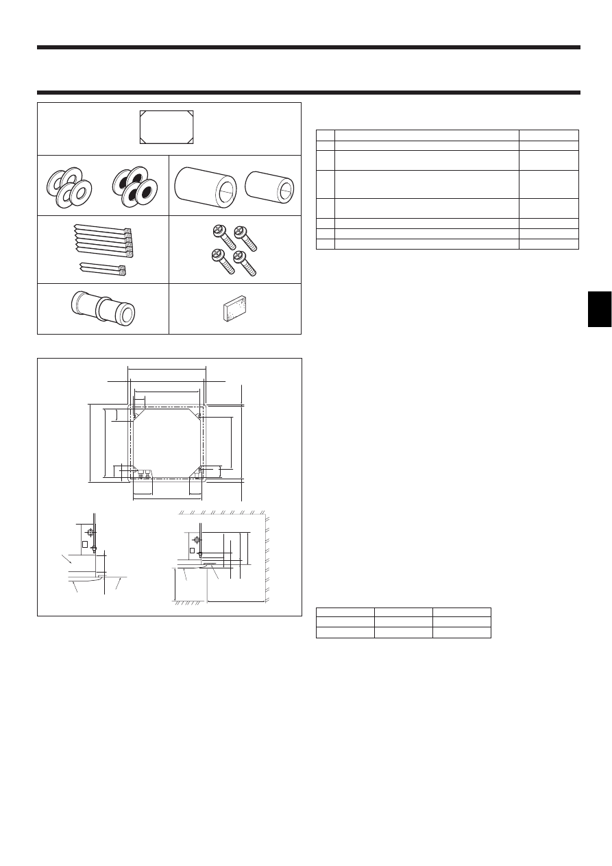
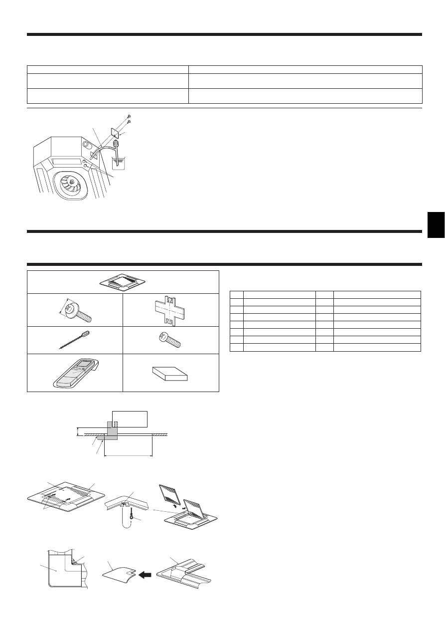
3.1. Check the indoor unit accessories (Fig. 3-1)
The indoor unit should be supplied with the following accessories.
Accessory name
Q’ty
1
Installation template
1
2
Washers (with insulation)
4
Washers (without insulation)
4
3
Pipe cover (for refrigerant piping joint)
Small diameter
1
Large diameter
1
4
Band (large)
6
Band (small)
2
5
Screw with washer (M5 × 25) for mounting grille
4
6
Drain socket
1
7
Insulation
1
3
2
5
4
7
6
Fig. 3-1
1
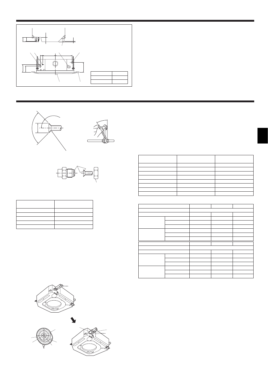
3.2. Ceiling openings and suspension bolt installation
locations (Fig. 3-2)
• Using the installation template (top of the package) and the gauge (supplied as an
accessory with the grille), make an opening in the ceiling so that the main unit can
be installed as shown in the diagram. (The method for using the template and the
gauge are shown.)
* Before using, check the dimensions of template and gauge, because they
change due to fluctuations of temperature and humidity.
* The dimensions of ceiling opening can be regulated within the range shown in
following diagram; so center the main unit against the opening of ceiling, en-
suring that the respective opposite sides on all sides of the clearance between
them becomes identical.
• Use M10 (3/8") suspension bolts.
* Suspension bolts are to be procured at the field.
• Install securely, ensuring that there is no clearance between the ceiling panel &
grille, and between the main unit & grille.
A Outer side of main unit
B Bolt pitch
C Ceiling opening
D Outer side of Grille
E Grille
F Ceiling
G Multi function casement (option)
H Entire periphery
* Note that the space between ceiling panel of the unit and ceiling slab and etc must be 10 to
15 mm.
159
192
159
159
98
860–910
20–45
20
–
45
20
–
45
20–45
810
950
840
197
159
605
840
950
860
–
910
A
B
C
D
C
B
D
A
135
F
G
E
17
+5
0
17
+5
0
50
–
70
105
30
C
D
Min. 1000
Min. 500
F
H
E
Fig. 3-2
Models
C
D
RP1.6,2,2.5,3
241
258
RP4,5,6
281
298
(mm)
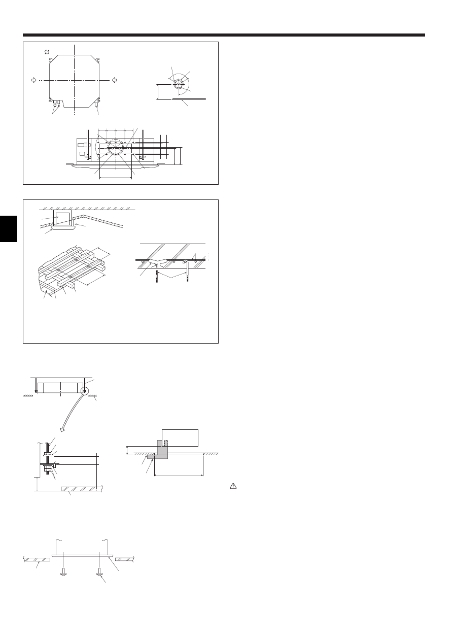
4
3. Installing the indoor unit
A Unit
B Grille
C Pillar
D Ceiling
E Rafter
F Beam
G Roof beam
H Use inserts rated at 100-150 kg
each (procure locally)
I Suspension bolts M10 (3/8") (procure
locally)
J Steel reinforcing rod
A
B
C
J
H
I
D
E
F G
605
810
1
2
Fig. 3-4
3.4. Suspension structure (Give site of suspension
strong structure) (Fig. 3-4)
• The ceiling work differs according to the construction of the building. Building con-
structors and interior decorators should be consulted for details.
(1) Extent of ceiling removal: The ceiling must be kept completely horizontal and the
ceiling foundation (framework: wooden slats and slat holders) must be reinforced
in order to protect the ceiling from vibration.
(2) Cut and remove the ceiling foundation.
(3) Reinforce the ends of the ceiling foundation where it has been cut and add ceiling
foundation for securing the ends of the ceiling board.
(4) When installing the indoor unit on a slanting ceiling, attach a pillar between the
ceiling and the grille and set so that the unit is installed horizontally.
1 Wooden structures
• Use tie beams (single storied houses) or second floor beams (two story houses) as
reinforcing members.
• Wooden beams for suspending air conditioners must be sturdy and their sides
must be at least 6 cm long if the beams are separated by not more than 90 cm and
their sides must be at least 9 cm long if the beams are separated by as much as
180 cm. The size of the suspension bolts should be ø10 (3/8"). (The bolts do not
come with the unit.)
2 Ferro-concrete structures
Secure the suspension bolts using the method shown, or use steel or wooden hang-
ers, etc. to install the suspension bolts.
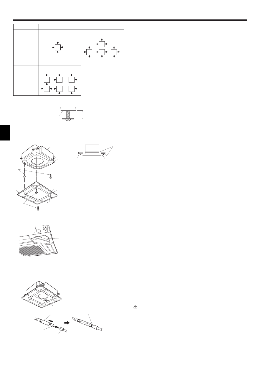
3.5. Unit suspension procedures (Fig. 3-5)
Suspend the main unit as shown in the diagram.
Figures given in parentheses represent the dimensions in case of installing optional
multi function casement.
1. In advance, set the parts onto the suspension bolts in the order of the washers
(with insulation), washers (without insulation) and nuts (double).
• Fit the washer with cushion so that the insulation faces downward.
• In case of using upper washers to suspend the main unit, the lower washers (with
insulation) and nuts (double) are to be set later.
2. Lift the unit to the proper height of the suspension bolts to insert the mounting
plate between washers and then fasten it securely.
3. When the main unit can not be aligned against the mounting hole on the ceiling, it
is adjustable owing to a slot provided on the mounting plate.
• Make sure that step A is performed within 17-22 mm. Damage could result by
failing to adhere to this range. (Fig. 3-6)
Caution:
Use the top half of the box as a protective cover to prevent dust or debris from
getting inside the unit prior to installation of the decorative cover or when ap-
plying ceiling materials.
3.6. Confirming the position of main unit and tighten-
ing the suspension bolts (Fig. 3-7)
• Using the gauge attached to the grille, ensure that the bottom of the main unit is
properly aligned with the opening of the ceiling. Be sure to confirm this, otherwise
condensation may form and drip due to air leakage etc.
• Confirm that the main unit is horizontally levelled, using a level or a vinyl tube filled
with water.
• After checking the position of the main unit, tighten the nuts of the suspension bolts
securely to fasten the main unit.
• The installation template (top of the package) can be used as a protective sheet to
prevent dust from entering the main unit when the grilles are left unattached for a while
or when the ceiling materials are to be lined after installation of the unit is finished.
* As for the details of fitting, refer to the instructions given on the Installation template.
A Suspension bolt
B Ceiling
C Nut
D Washer (with insulation)
E Mounting plate
F Washer (without insulation)
G Check using the Installation gauge
A
D
C
B
A=17
+5
0
C
D
B
A
17
105
(240
)
+5 0
A
B
A
C
D
E
F
C
B
G
Min. 30
A Main unit
B Ceiling
C Installation template (top of the
package)
D Screw with washer (Accessory)
A Main unit
B Ceiling
C Gauge
D Ceiling opening dimensions
Fig. 3-5
Fig. 3-6
Fig. 3-7
D
E
A
C
A
B
90
90
100
100
130
350
70
°
100
G
F
H
I
J
∗
155
∗
167
L
K
M
N
O
∗
158
120
°
120°
Fig. 3-3
3.3. Branch duct hole and fresh air intake hole (Fig. 3-3)
At the time of installation, use the duct holes (cut out) located at the positions shown
in following diagram, as and when required.
• A fresh air intake hole for the optional multi function casement can also be made.
Note:
The figure marked with * in the drawing represent the dimensions of the main
unit excluding those of the optional multi function casement.
When installing the optional multi function casement, add 135 mm to the di-
mensions marked on the figure.
When installing the branch ducts, be sure to insulate adequately. Otherwise
condensation and dripping may occur.
A Branch duct hole
B Indoor unit
C Fresh air intake hole
D Drain pipe
E Refrigerant pipe
F Branch duct hole diagram (view from
either side)
G Cut out hole
H 14-ø2.8 burring hole
I ø150 cut out hole
J ø175 burring hole pitch
K Fresh air intake hole diagram
L 3-ø2.8 burring hole
M ø125 burring hole pitch
N ø100 cut out hole
O Ceiling
5
4. Installing the pipes
4.1. Refrigerant and drainage piping locations of indoor
unit
The figure marked with * in the drawing represent the dimensions of the main unit
excluding those of the optional multi function casement. (Fig. 4-1)
A Drain pipe
B Ceiling
C Grille
D Refrigerant pipe (liquid)
E Refrigerant pipe (gas)
F Water supply inlet
G Main unit
• When the optional multi-functional casement is installed, add 135 mm to the di-
mensions marked on the figure.
(mm)
Models
A
RP1.6, 2, 2.5, 3
80
RP4, 5, 6
84
16
89
A
98
G
A
∗170
∗140
∗190
60
286
374
A
F
D
E
B
C
Fig. 4-1
5. Refrigerant piping work
5.1. Connecting pipes (Fig. 5-1)
• When commercially available copper pipes are used, wrap liquid and gas pipes
with commercially available insulation materials (heat-resistant to 100 °C or more,
thickness of 12 mm or more).
• The indoor parts of the drain pipe should be wrapped with polyethylene foam insu-
lation materials (specific gravity of 0.03, thickness of 9 mm or more).
• Apply thin layer of refrigerant oil to pipe and joint seating surface before tightening
flare nut.
• Use two wrenches to tighten piping connections.
• Use refrigerant piping insulation provided to insulate indoor unit connections. Insu-
late carefully.
A Flare cutting dimensions
Copper pipe O.D.
Flare dimensions
(mm)
øA dimensions (mm)
ø6.35
8.7 - 9.1
ø9.52
12.8 - 13.2
ø12.7
16.2 - 16.6
ø15.88
19.3 - 19.7
ø19.05
23.6 - 24.0
90
°
±0.5
°
ø
A
R0.4~R0.8
A
45°±2°
B
C
D
Fig. 5-1
B
D
E
A
C
F
J
H
I
B,C
F
G
A Refrigerant pipe and insulating ma-
terial
B Pipe cover (large)
C Pipe cover (small)
D Refrigerant pipe (gas)
E Refrigerant pipe (liquid)
F Band
G Cross-sectional view of connection
H Pipe
I Insulating material
J Squeeze
5.2. Indoor unit (Fig. 5-2)
Heat insulation for refrigerant pipes:
1 Wrap the enclosed large-sized pipe cover around the gas pipe, making sure that
the end of the pipe cover touches the side of the unit.
2 Wrap the enclosed small-sized pipe cover around the liquid pipe, making sure
that the end of the pipe cover touches the side of the unit.
3 Secure both ends of each pipe cover with the enclosed bands. (Attach the bands
20 mm from the ends of the pipe cover.)
• After connecting the refrigerant piping to the indoor unit, be sure to test the pipe
connections for gas leakage with nitrogen gas. (Check that there is no refrigerant
leakage from the refrigerant piping to the indoor unit.)
5.3. For twin/triple combination
Refer to the outdoor unit installation manual.
Copper pipe O.D.
Flare nut O.D.
Tightening torque
(mm)
(mm)
(N·m)
ø6.35
17
14 - 18
ø6.35
22
34 - 42
ø9.52
22
34 - 42
ø12.7
26
49 - 61
ø12.7
29
68 - 82
ø15.88
29
68 - 82
ø15.88
36
100 - 120
ø19.05
36
100 - 120
*1: The flare nut is attached to its pipe.
*2: The flare nut is in the outdoor unit accessory.
Do not use the flare nut attached. If it is used, a gas leakage or even a pipe
extraction may occur.
Refer to the outdoor unit installation manual for the specification of connecting pipes.
C Apply refrigerating machine oil over the entire flare seat surface.
D Use the flare nuts as follows.
Indoor unit
RP1.6, 2
RP2.5, 3
RP4-6
Refrigerant
R407C
Joint outdoor unit
PU(H)-P1.6/2 PU(H)-P2.5/3 PU(H)-P4/5/6
Gas side
Pipe size (mm)
ø15.88
ø15.88
ø19.05
Indoor nut
*1
*1
*1
Outdoor nut
*1
*1
*1
Liquid side
Pipe size (mm)
ø9.52
ø9.52
ø9.52
Indoor nut
*1
*1
*1
Outdoor nut
*1
*1
*1
Indoor unit
RP1.6, 2
RP2.5, 3
RP4-6
Refrigerant
R410A
Joint outdoor unit
PUHZ-RP1.6/2 PUHZ-RP2.5/3 PUHZ-RP4/5/6
Gas side
Pipe size (mm)
ø12.7
ø15.88
ø15.88
Indoor nut
*2
*1
*2
Outdoor nut
*1
*1
*1
Liquid side
Pipe size (mm)
ø6.35
ø9.52
ø9.52
Indoor nut
*2
*1
*1
Outdoor nut
*1
*1
*1
B Flare nut tightening torque
Fig. 5-2
6
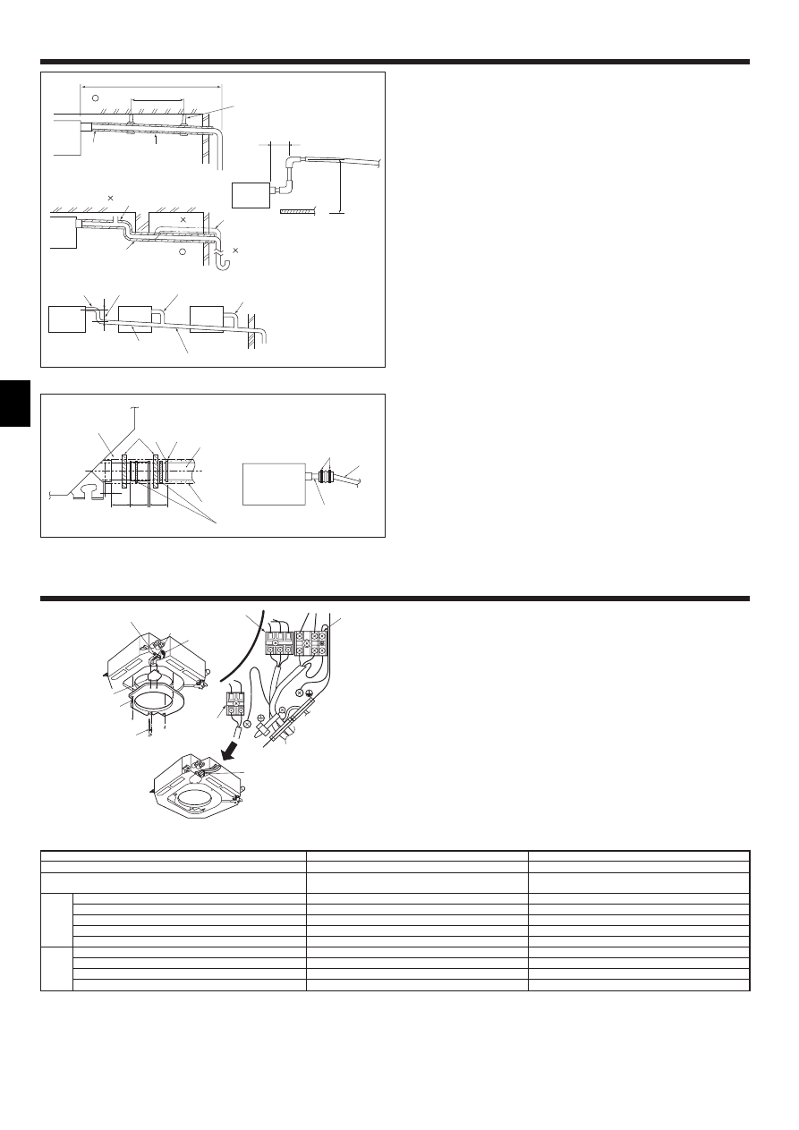
6. Drainage piping work
6.1. Drainage piping work (Fig. 6-1)
• Use VP25 (O. D. ø32 PVC TUBE) for drain piping and provide 1/100 or more down-
ward slope.
• Be sure to connect the piping joints using a polyvinyl type adhesive.
• Observe the figure for piping work.
• Use the included drain hose to change the extraction direction.
Max. 20m
1.5–2m
A
B
C
B
M
L
K
D
E
D
H
I
G
D
F
F
F
Max. 15cm
J
F
G
11
25
25
25
B
A
C
K
F
L
H
D
E
E
I
J
C,K
Fig. 6-1
Fig. 6-2
(mm)
1 Correct piping
2 Wrong piping
A Insulation (9 mm or more)
B Downward slope (1/100 or more)
C Support metal
K Air bleeder
L Raised
M Odor trap
Grouped piping
D O. D. ø32 PVC TUBE
E Make it as large as possible
F Indoor unit
G Make the piping size large for grouped piping.
H Downward slope (1/100 or more)
I O. D. ø38 PVC TUBE for grouped piping.
(9 mm or more insulation)
J Up to 85 cm
1. Connect the drain socket (supplied with the unit) to the drain port. (Fig. 6-2)
(Affix the tube using PVC adhesive then secure it with a band.)
2. Install a locally purchased drain pipe (PVC pipe, O.D. ø32).
(Affix the pipe using PVC adhesive then secure it with a band.)
3. Insulate the tube and pipe. (PVC pipe, O.D. ø32 and socket)
4. Check that drain flows smoothly.
5. Insulate the drain port with insulating material, then secure the material with a
band. (Both insulating material and band are supplied with the unit.)
A Unit
B Insulating material
C Band (large)
D Drain port (transparent)
E Insertion margin
F Matching
G Drain pipe (O.D. ø32 PVC TUBE)
H Insulating material (purchased locally)
I Transparent PVC pipe
J O.D. ø32 PVC TUBE (Slope 1/100 or more)
K Band (small)
L Drain socket
7. Electrical work
7.1. Indoor unit (Fig. 7-1)
1. Remove the two electrical wiring service panels.
2. Wire the power cable and control cable separately through the respective wiring
entries given in the diagram.
• Do not allow slackening of the terminal screws.
• Leave excess cable so that the electrical box can be suspended below the unit
during servicing. (Approx. 50 to 100 mm)
A Entry for control cable
B Entry for power
C Clamp
D Service panel for indoor controller switch setting
E Service panel for electrical wiring
F Electric heater power supply terminals (PLH models)
G Indoor / Outdoor unit connecting terminals
H Remote controller connector
I Secure with the clamp
J Intake sensor
K Holder
Fig. 7-1
A
E
D
J,K
B
C
I
G
F
H
N
L
S3
S2
S1
1
2
*1. A breaker with at least 3 mm contact separation in each pole shall be provided. Use non-fuse breaker (NF) or earth leakage breaker (NV).
*2. A 10 m wire is attached in the remote controller accessory.
*3. The figures are NOT always against the ground.
S3 terminal has DC 24 V against S2 terminal. However between S3 and S1, these terminals are not electrically insulataed by the transformer or other device.
Notes: 1. Wiring size must comply with the applicable local and national code.
2. Power supply cords and Indoor unit/Outdoor unit connecting cords shall not be lighter than polychloroprene sheathed flexible cord. (Design 245 IEC 57)
3. Install an earth longer and thicker than other cables.
Indoor unit model
Indoor unit power supply (Heater)
Indoor unit input capacity (Heater)
*1
Main switch (Breaker)
Indoor unit power supply (Heater)
Indoor unit power supply (Heater) earth
Indoor unit-Outdoor unit
Indoor unit-Outdoor unit earth
Remote controller-Indoor unit
*2
Indoor unit (Heater) L-N
*3
Indoor unit-Outdoor unit S1-S2
*3
Indoor unit-Outdoor unit S2-S3
*3
Remote controller-Indoor unit
*3
PLA
PLH
–
~/N (single), 50Hz, 220-230-240V
–
16 A
–
2 × Min. 1.5
–
1 × Min. 1.5
3 × 2.5 (polar)
3 × 2.5 (polar)
1 × Min. 2.5
1 × Min. 2.5
2 × 0.69 (Non-polar)
2 × 0.69 (Non-polar)
–
AC 220-230-240V
AC 220-230-240V
AC 220-230-240V
DC24V
DC24V
DC14V
DC14V
C
ir
c
u
it
ra
ti
n
g
W
ir
in
g
Wire
No
.
×
siz
e
(mm
2
)

7
7. Electrical work
7.2. Remote controller
7.2.1. For wired remote controller
1) Installing procedures
(1) Select an installing position for the remote controller. (Fig. 7-2)
The temperature sensors are located on both remote controller and indoor unit.
s Procure the following parts locally:
Two piece switch box
Thin copper conduit tube
Lock nuts and bushings
A Remote controller profile
B Required clearances surrounding the remote controller
C Installation pitch
(2) Seal the service entrance for the remote controller cord with putty to prevent pos-
sible invasion of dew drops, water, cockroaches or worms. (Fig. 7-3)
A For installation in the switch box:
B For direct installation on the wall select one of the following:
• Prepare a hole through the wall to pass the remote controller cord (in order to run
the remote controller cord from the back), then seal the hole with putty.
• Run the remote controller cord through the cut-out upper case, then seal the cut-
out notch with putty similarly as above.
B-1. To lead the remote controller cord from the back of the controller:
B-2. To run the remote controller cord through the upper portion:
(3) For direct installation on the wall
C Wall
D Conduit
E Lock nut
F Bushing
G Switch box
H Remote controller cord
I Seal with putty
J Wood screw
2) Connecting procedures (Fig. 7-4)
1 Connect the remote controller cord to the terminal block.
A To TB5 on the indoor unit
B TB6 (No polarity)
2 Set the dip switch No.1 shown below when using two remote controller’s for the
same group.
C Dip switches
Setting the dip switches
The dip switches are at the bottom of the remote controller. Remote controller Main/
Sub and other function settings are performed using these switches. Ordinarily, only
change the Main/Sub setting of SW No.1. (The factory settings are all “ON”.)
7.2.2. For wireless remote controller
1) Installation area
• Area in which the remote controller is not exposed to direct sunshine.
• Area in which there is no nearby heating source.
• Area in which the remote controller is not exposed to cold (or hot) winds.
• Area in which the remote controller can be operated easily.
• Area in which the remote controller is beyond the reach of children.
2) Installation method (Fig. 7-5)
1 Attach the remote controller holder to the desired location using two tapping screws.
2 Place the lower end of the controller into the holder.
A Remote controller
B Wall
C Display panel
D Receiver
• The signal can travel up to approximately 7 meters (in a straight line) within 45
degrees to both right and left of the center line of the receiver.
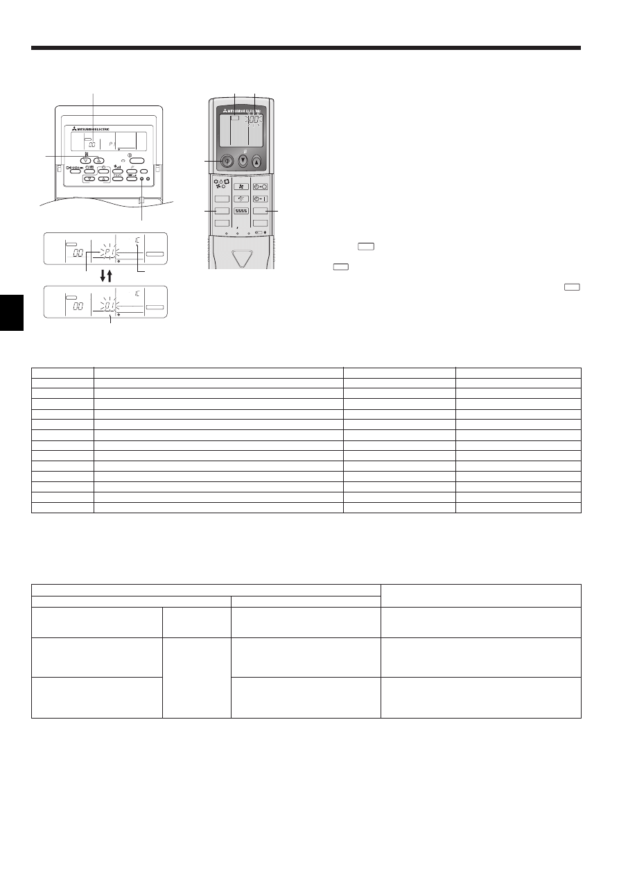
3) Setting (Fig. 7-6)
1 Insert batteries.
2 Press the SET button with something sharp at the end.
MODEL SELECT
blinks and Model No. is lighted.
3 Press the temp
button to set the Model No.
4 Press the SET button with something sharp at the end.
MODEL SELECT
and Model No. are lighted for three seconds, then turned off.
30
46
30
30
120
83.5
A
B
C
F
A
H
C
D
E
G
I
I
I
H
B
J
H
B-1.
B-2.
Fig. 7-3
A
AB
TB6
B
1
2
3
4
ON
1
2
3
4
ON
C
<SW No. 1>
SW contents Main
Remote controller Main/Sub setting
ON/OFF
Comment
Set one of the two remote controllers at one group to “Main”
Main/Sub
<SW No. 2>
SW contents Main
When remote controller power turned on
ON/OFF
Comment
When you want to return to the timer mode when the power is restored
after a power failure when a Program timer is connected, select “Timer
mode”.
Normally on/Timer mode on
<SW No. 3>
SW contents Main
Cooling/heating display in AUTO mode
ON/OFF
Comment
When you do not want to display “Cooling” and “Heating” in the Auto
mode, set to “No”.
Yes/No
<SW No. 4>
SW contents Main
Intake temperature display
ON/OFF
Comment
When you do not want to display the intake temperature, set to “No”.
Yes/No
Indoor
Outdoor
A Model No.
PLH, PCH, PKH (1.6, 2)
PUH
001
PLA, PCA, PKA (1.6, 2)
PUH, PUHZ
001
PU
033
PKH (2.5, 3, 4)
PUH
003
PKA (2.5, 3, 4)
PUH, PUHZ
003
PU
035
D
B
1
C
A
2
ON/OFF
TEMP
FAN
VANE
TEST RUN
AUTO STOP
AUTO START
h
min
LOUVER
MODE
CHECK
RESET
SET
CLOCK
MODEL SELECT
2,4
3
A
Fig. 7-5
Fig. 7-6
Fig. 7-2
Fig. 7-4
8
4) Assigning a remote controller to each unit (Fig. 7-7)
Each unit can be operated only by the assigned remote controller.
Make sure each pair of an indoor unit PC board and a remote controller is assigned
to the same pair No.
5) Wireless remote controller pair number setting operation
1 Press the SET button with something sharp at the end.
Start this operation from the status of remote controller display turned off.
MODEL SELECT
blinks and Model No. is lighted.
2 Press the
min
button twice continuously.
Pair No. “0” blinks.
3 Press the temp
button to set the pair number you want to set.
4 Press the SET button with something sharp at the end.
Set pair number is lighted for three seconds then turned off.
A Pair No. of wireless remote controller
Indoor PC board
0
Factory setting
1
Cut J41
2
Cut J42
3–9
Cut J41, J42
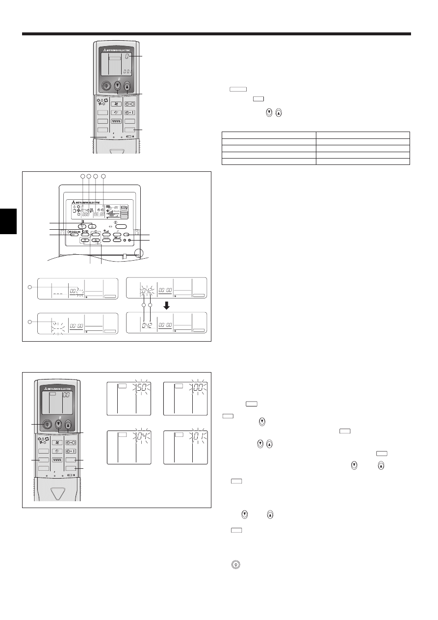
7.3. Function settings
7.3.1. For wired remote controller (Fig. 7-8)
Changing the power voltage setting
• Be sure to change the power voltage setting depending on the voltage used.
1 Go to the function setting mode.
Switch OFF the remote controller.
Press the A and B buttons simultaneously and hold them for at least 2
seconds. FUNCTION will start to flash.
2 Use the C button to set the refrigerant address (3) to 00.
3 Press D and [--] will start to flash in the unit number (4) display.
4 Use the C button to set the unit number (4) to 00.
5 Press the E MODE button to designate the refrigerant address/unit number. [--]
will flash in the mode number (
1) display momentarily.
6 Press the F buttons to set the mode number (1) to 04.
7 Press the G button and the current set setting number (2) will flash.
Use the F button to switch the setting number in response to the power supply
voltage to be used.
Power supply voltage
240 V
: setting number = 1
220 V, 230 V : setting number = 2
8 Press the MODE button E and mode and the setting number (1) and (2) will
change to being on constantly and the contents of the setting can be confirmed.
9 Press the FILTER A and TEST RUN B buttons simultaneously for at least two
seconds. The function selection screen will disappear momentarily and the air
conditioner OFF display will appear.
7.3.2. For wireless remote controller (Fig. 7-9)
Changing the power voltage setting
Be sure to change the power voltage setting depending on the voltage used.
1 Go to the function select mode
Press the
CHECK
button F twice continuously.
(Start this operation from the status of remote controller display turned off.)
CHECK
is lighted and “00” blinks.
Press the temp
button C once to set “50”. Direct the wireless remote controller
toward the receiver of the indoor unit and press the
h
button A.
2 Setting the unit number
Press the temp
button C and D to set the unit number “00”. Direct the wireless
remote controller toward the receiver of the indoor unit and press the
min
button B.
3 Selecting a mode
Enter 04 to change the power voltage setting using the
C and
D buttons.
Direct the wireless remote controller toward the receiver of the indoor unit and press
the
h
button A.
Current setting number:
1 = 1 beep (one second)
2 = 2 beeps (one second each)
3 = 3 beeps (one second each)
4 Selecting the setting number
Use the
C and
D buttons to change the power voltage setting to 01 (240 V).
Direct the wireless remote controller toward the sensor of the indoor unit and press
the
h
button A.
5 To select multiple functions continuously
Repeat steps 3 and 4 to change multiple function settings continuously.
6 Complete function selection
Direct the wireless remote controller toward the sensor of the indoor unit and press
the
button E.
Note:
Whenever changes are made to the function settings after installation or main-
tenance, be sure to record the changes with a mark in the “Setting” column of
the Function table.
ON/OFF
TEMP
FAN
VANE
TEST RUN
AUTO STOP
AUTO START
h
min
LOUVER
MODE
CHECK
RESET
SET
CLOCK
MODEL SELECT
1,4
3
A
2
Fig. 7-7
ON/OFF
CENTRALLY CONTROLLED
ERROR CODE
CLOCK
ON
OFF
˚C
CHECK
CHECK MODE
FILTER
TEST RUN
FUNCTION
˚C
1Hr.
NOT AVAILABLE
STAND BY
DEFROST
FILTER
CHECK TEST
TEMP.
TIMER SET
F
G
E
C
D
B
A
4
3
2
1
STAND BY
DEFROST
INDOOR UNIT
ADDRESS NO
CLOCK
ON
OFF
˚C
1Hr.
˚C
CHECK MODE
FILTER
CLOCK
FUNCTION
4
1
STAND BY
DEFROST
INDOOR UNIT
ADDRESS NO
CLOCK
ON
OFF
˚C
1Hr.
˚C
CHECK MODE
FILTER
CLOCK
FUNCTION
STAND BY
DEFROST
INDOOR UNIT
ADDRESS NO
CLOCK
ON
OFF
˚C
1Hr.
˚C
CHECK MODE
FILTER
CLOCK
FUNCTION
STAND BY
DEFROST
INDOOR UNIT
ADDRESS NO
CLOCK
ON
OFF
˚C
1Hr.
˚C
CHECK MODE
FILTER
CLOCK
FUNCTION
2
1
Fig. 7-8
3
CHECK
4
CHECK
ON/OFF
TEMP
FAN
VANE
TEST RUN
AUTO STOP
AUTO START
h
min
LOUVER
MODE
CHECK
RESET
SET
CLOCK
CHECK
E
C,D
F
A
B
Fig. 7-9
2
CHECK
CHECK
1
7. Electrical work
⁄ Mode number
⁄ Setting number
⁄ Refrigerant address
⁄ Unit number
1
2
3
4
9
7. Electrical work
Function table
Select unit number 00
Mode
Power failure automatic recovery
Indoor temperature detecting
LOSSNAY connectivity
Power voltage
Auto mode (only for PUHZ)
Settings
Not available
Available
Indoor unit operating average
Set by indoor unit’s remote controller
Remote controller’s internal sensor
Not Supported
Supported (indoor unit is not equipped with outdoor-air intake)
Supported (indoor unit is equipped with outdoor-air intake)
240 V
220 V, 230 V
Energy saving cycle automatically enabled
Energy saving cycle automatically disabled
Mode no.
Setting no. Initial setting
setting
01
1
2
1
02
2
3
1
03
2
3
04
1
2
05
1
2
Mode
Filter sign
Fan speed
No. of air outlets
Installed options (high-performance filter)
Up/down vane setting
Energy saving air flow
(Heating mode)
Settings
100Hr
2500Hr
No filter sign indicator
Standard (PLH/PLA)/Silent (PCH/PCA)
High ceiling 1 (PLH/PLA)/Standard (PCH/PCA)
High ceiling 2 (PLH/PLA)/High ceiling (PCH/PCA)
4 directions
3 directions
2 directions
Not supported
Supported
No vanes
Equipped with vanes (vanes angle setup 1)
Equipped with vanes (vanes angle setup 2)
Disabled
Enabled
Mode no.
Setting no. Initial setting
setting
1
07
2
3
1
08
2
3
1
09
2
3
10
1
2
11
1
2
3
12
1
2
Select unit numbers 01 to 03 or all units (AL [wired remote controller]/07 [wireless remote controller])
8. Test run
8.1. Before test run
s After completing installation and the wiring and piping of the indoor and outdoor
units, check for refrigerant leakage, looseness in the power supply or control
wiring, wrong polarity, and no disconnection of one phase in the supply.
s Use a 500-volt megohmmeter to check that the resistance between the power
supply terminals and ground is at least 1.0MΩ.
s Do not carry out this test on the control wiring (low voltage circuit) termi-
nals.
Warning:
Do not use the air conditioner if the insulation resistance is less than 1.0MΩ.
Insulation resistance
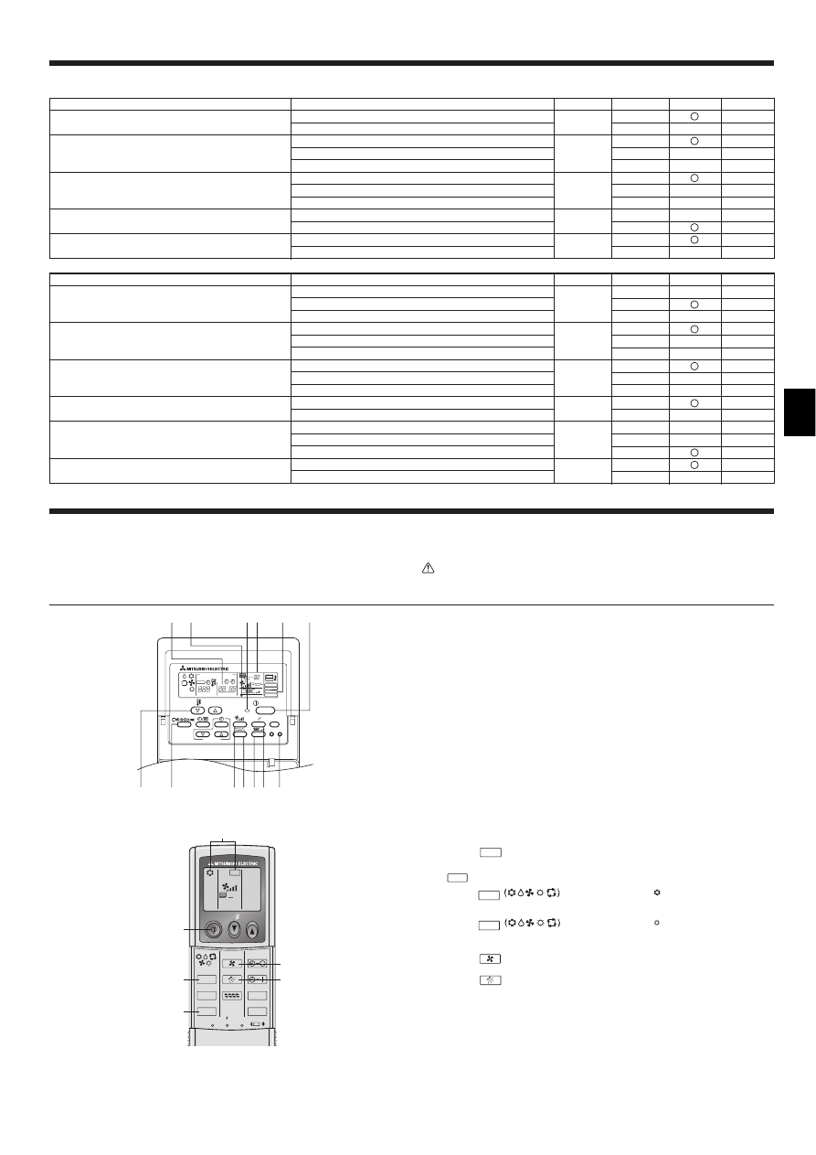
8.2. Test run
The following 3 methods are available.
8.2.1. Using wired remote controller (Fig. 8-1)
1 Turn on the power at least 12 hours before the test run.
2 Press the [TEST] button twice. ➡ “TEST RUN” liquid crystal display
3 Press the [Mode selection] button. ➡ Make sure that wind is blown out.
4 Press the [Mode selection] button and switch to the cooling (or heating) mode.
➡ Make sure that cold (or warm) wind is blown out.
5 Press the [Fan speed] button. ➡ Make sure that the wind speed is switched.
6 Switch the wind direction by pressing the [Airflow] or [Louver] button.
➡ Make sure that horizontal outlet, downward outlet, and other wind direction
adjustments are possible.
➡ Check operation of the outdoor unit fan.
7 Release test run by pressing the [ON/OFF] button. ➡ Stop
8 After the checks, always turn off the power.
8.2.2. Using wireless remote controller (Fig. 8-2)
1 Turn on the power to the unit at least 12 hours before the test run.
2 Press the
TEST RUN
button twice continuously.
(Start this operation from the status of remote controller display turned off.)
A TEST RUN and current operation mode are displayed.
3 Press the
MODE
button to activate
COOL
mode, then check whether
cool air is blown out from the unit.
4 Press the
MODE
button to activate
HEAT
mode, then check whether
warm air is blown out from the unit.
5 Press the
FAN
button and check whether fan speed changes.
6 Press the
VANE
button and check whether the auto vane operates properly.
7 Press the ON/OFF button to stop the test run.
Note:
• Point the remote controller towards the indoor unit receiver while following
steps 2 to 7.
• It is not possible to run the in FAN, DRY or AUTO mode.
ON/OFF
CENTRALLY CONTROLLED
ERROR CODE
CLOCK
ON
OFF
˚C
CHECK
CHECK MODE
FILTER
TEST RUN
FUNCTION
˚C
1Hr.
NOT AVAILABLE
STAND BY
DEFROST
FILTER
CHECK TEST
TEMP.
TIMER SET
D
E
F
H
IJKL M
G
C
B
A
ON/OFF
TEMP
FAN
VANE
TEST RUN
AUTO STOP
AUTO START
h
min
LOUVER
MODE
CHECK
RESET
SET
CLOCK
TEST RUN
5
7
A
3,4
2
6
Fig. 8-2
Fig. 8-1
10
8.2.3. Using SW4 in outdoor unit
Refer to the outdoor unit installation manual.
8.3. Self-check
8.3.1. Wired remote controller (Fig. 8-3)
1 Turn on the power.
2 Press the [CHECK] button twice.
3 Set refrigerant address with [TEMP] button if system control is used.
4 Press the [ON/OFF] button to stop the self-check.
A CHECK button
B Refrigerant address
C TEMP. button
D IC: Indoor unit
OC: Outdoor unit
E Check code
F Unit address
8.3.2. Wireless remote controller (Fig. 8-4)
1 Turn on the power.
2 Press the
CHECK
button twice.
(Start this operation from the status of remote controller display turned off.)
A CHECK begins to light.
B «00» begins to blink.
3 While pointing the remote controller toward the unit’s receiver, press the
h
button. The check code will be indicated by the number of times that the buzzer
sounds from the receiver section and the number of blinks of the operation lamp.
4 Press the ON/OFF button to stop the self-check.
8. Test run
ON/OFF
TEMP
FAN
VANE
TEST RUN
AUTO STOP
AUTO START
h
min
LOUVER
MODE
CHECK
RESET
SET
CLOCK
CHECK
2
4
A
3
B
Fig. 8-4
ON/OFF
CHECK
FILTER
CHECK TEST
TEMP.
TIMER SET
B
C
A
STAND BY
DEFROST
INDOOR UNIT
ADDRESS NO
ERROR CODE
OA UNIT ADDRESS NO
CENTRALLY CONTROLLED
CLOCK
ON
OFF
˚C
1Hr.
NOT AVAILABLE
˚C
CHECK MODE
FILTER
CHECK
FUNCTION
STAND BY
DEFROST
INDOOR UNIT
ADDRESS NO
ERROR CODE
OA UNIT ADDRESS NO
CENTRALLY CONTROLLED
CLOCK
ON
OFF
˚C
1Hr.
NOT AVAILABLE
˚C
CHECK MODE
FILTER
CHECK
FUNCTION
a)
D
E
F
Fig. 8-3
• For description of each check code, refer to the following table.
1 Check code
Symptom
2 Buzzer sound
3 OPE LED
P1
Intake sensor error
Single beep × 1
Lit for 1 sec. × 1
P2
Pipe sensor error
Single beep × 2
Lit for 1 sec. × 2
P4
Drain sensor error
Single beep × 4
Lit for 1 sec. × 4
P5
Drain pump error
Single beep × 5
Lit for 1 sec. × 5
P6
Freezing / Overheating safeguard operation
Single beep × 6
Lit for 1 sec. × 6
P8
Pipe temperature error
Single beep × 8
Lit for 1 sec. × 8
P9
TH5 sensor error
Single beep × 2
Lit for 1 sec. × 2
U0–UP
Outdoor unit error
Double beep × 1
Lit for 0.4 sec. + 0.4 sec. × 1
F1–FA
Outdoor unit error
Double beep × 1
Lit for 0.4 sec. + 0.4 sec. × 1
E0–E5
Signal error between remote controller and indoor units
Sounds other than above
Lights other than above
E6–EF
Communication error between indoor and outdoor units
Sounds other than above
Lights other than above
– –
No alarm history
No sound
Not lit
F F F F
No unit
Triple beep
Not lit
• On wireless remote controller
2 The continuous buzzer sounds from receiving section of indoor unit.
3 Blink of operation lamp
• On wired remote controller
1 Check code displayed in the LCD.
• If the unit cannot be operated properly after the above test run has been performed, refer to the following table to remove the cause.
Symptom
Cause
Wired remote controller
LED 1, 2 (PCB in outdoor unit)
H0
H0 → Error code
Display messages do not apper even
when operation switch is turned ON
(operation lamp does not light up).
For about 2
minutes following
power-on
After about 2
minutes has
expired following
power-on
After LED 1, 2 are lighted, LED 2 is turned off,
then only LED 1 is lighted. (Correct operation)
Only LED 1 is lighted. → LED 1, 2 blink.
Only LED 1 is lighted. → LED 1 blinks twice,
LED 2 blinks once.
• For about 2 minutes following power-on, operation of the
remote controller is not possible due to system start-up. (Cor-
rect operation)
• Connector for the outdoor unit’s protection device is not con-
nected.
• Reverse or open phase wiring for the outdoor unit’s power
terminal block (L1, L2, L3)
• Incorrect wiring between indoor and outdoor units (incorrect
polarity of S1, S2, S3)
• Remote controller wire short
On the wireless remote controller with condition above, following phenomena takes place.
• No signals from the remote controller are accepted.
• OPE lamp is blinking.
• The buzzer makes a short pipng sound.
11
Note:
Operation is not possible for about 30 seconds after cancellation of function selection. (Correct operation)
For description of each LED (LED1, 2, 3) provided on the indoor controller, refer to the following table.
LED1 (power for microcomputer)
Indicates whether control power is supplied. Make sure that this LED is always lit.
LED2 (power for remote controller)
Indicates whether power is supplied to the remote controller. This LED lights only in the case of the
indoor unit which is connected to the outdoor unit refrigerant address “0”.
LED3 (communication between indoor and outdoor units)
Indicates state of communication between the indoor and outdoor units. Make sure that this LED is
always blinking.
8. Test run
8.4. Check of drainage (Fig. 8-5)
• During the trial run, ensure the water is being properly drained out and that no
water is leaking from joints.
• Always check this during installation even if the unit is not required to provide cool-
ing/drying at that time.
• Similarly, check the drainage before finishing ceiling installation in a new premises.
(1) Remove the cover of the water supply inlet and add about 1000 cc of water using
a water supply pump etc. During this process, be careful not to spray water into
the drain pump mechanism.
(2) Confirm that water is being drained out through the drainage outlet, after switch-
ing over from remote control mode to trial run mode.
(3) After checking the drainage, ensure that the cover is replaced and the power
supply is isolated.
(4) After confirming the drainage system is functioning, replace the drain plug.
A
B
C
D
E
Fig. 8-5
A Insert the pump end 3 to 5 cm
B Cover of water supply inlet
C About 1000 cc
D Water
E Drain plug
9. System controll
Refer to the outdoor unit installation manual.
10.1. Checking the contents (Fig. 10-1)
• This kit contains this manual and the following parts.
Accessory name
Q’ty
Remark
1
Grille
1
950 × 950 (mm)
2
Screw with captive washer
4
M5 × 0.8 × 25
3
Gauge
1
(Divided into four parts)
4
Fastener
2
5
Screw
4
4 × 8
6
Wireless remote controller
1
for PLP-6AALM
7
Wired remote controller
1
for PLP-6AAM
10. Installing the grille
1
4
5
6
7
ø
20
ON/OFF
2
3
Fig. 10-1
Fig. 10-2
A
D
C
B
A=17
+5
0
Fig. 10-3
B
A
C
1
1
D
E
2
F
G
F
B
1
10.2. Preparing to attach the grille (Fig. 10-2)
• With the gauge 3 supplied with this kit, adjust and check the positioning of the unit
relative to the ceiling. If the unit is not properly positioned relative to the ceiling, it
may allow air leaks or cause condensation to collect.
• Make sure that the opening in the ceiling is within the following tolerances:
860 × 860 - 910 × 910
• Make sure that step A is performed within 17-22 mm. Damage could result by fail-
ing to adhere to this range.
A Main unit
B Ceiling
C Gauge 3 (inserted into the unit)
D Ceiling opening dimensions
10.2.1. Removing the intake grille (Fig. 10-3)
• Slide the levers in the direction indicated by the arrow 1 to open the intake grille.
• Unlatch the hook that secures the grille.
* Do not unlatch the hook for the intake grille.
• With the intake grille in the “open” position, remove the hinge of the intake grille
from the grille as indicated by the arrow 2.
10.2.2. Removing the corner panel (Fig. 10-4)
• Remove the screw from the corner of the corner panel. Slide the corner panel as
indicated by the arrow 1 to remove the corner panel.
A Intake grille
B Grille
C Intake grille levers
D Grille hook
E Hole for the grille’s hook
F Corner panel
G Screw
Fig. 10-4
12
10.4. Installing the grille
10.4.1. Preparations (Fig. 10-5)
• Install the two enclosed screws with washer 2 in the main unit (at the corner drain
pipe area and at the opposite corner) as shown in the diagram.
Fig. 10-5
15-20
A
B
A
C
D
E
F
I
G
H
A
C
D
B
A Main unit
B Detailed diagram of installed screw with
washer 2.
C Corner drain pipe area
D Screw with washer 2 (for temporary use)
E Grille
F Screw with washer 2
G Hole A
H Hole B
I Bell shaped hole
Fig. 10-6
10.4.2. Temporary installation of the grille (Fig. 10-6)
• Temporarily secure the grille using the bell shaped holes by aligning the corner
drain pipe area of the main unit with the two holes of the grille that are marked A
and B.
* Make sure that the lead wiring of the grille does not get pinched between the
grille and the main unit.
10.4.3. Securing the grille (Fig. 10-7)
• Secure the grille to the main unit by tightening the previously installed two screws
(with captive washer) as well as the two remaining screws (with captive washer).
* Make sure that there are no gaps between the main unit and the grille or the
grille and the ceiling.
Fixing gaps between the grille and the ceiling
With the grille attached, adjust the height of the main unit to close the gap.
E
A Ceiling
B Main unit
C Grille
D Make sure that there are no gaps.
E Adjust the nut of the main unit using a
wrench, etc.
Fig. 10-7
A
D
C
B
E
Fig. 10-8
A Clamp of the main unit
B Tube
C Connector of the main unit
D Grille connector
E Fastener
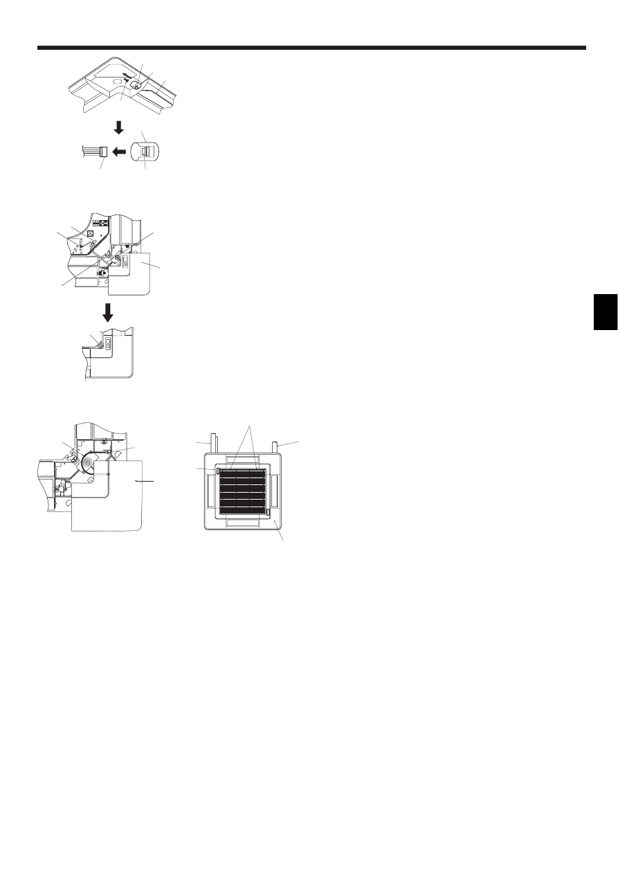
10.4.4. Wire connection (Fig. 10-8)
• Be sure to connect the unit to the connector (white, 10-pole). Next, attach the white
glass tube that comes with the main unit so that the tube covers the connector.
Close the opening of the glass tube with the fastener.
• Make sure that there is no slack in the lead wire at the clamp of the main unit.
Warning:
If the connector is not covered with the glass tube, tracking resulting in fire
may occur.
10.3. Selection of the air outlets
For this grille the discharge direction is available in 11 patterns. Also, by setting the
Remote controller to the appropriate settings, you can adjust the air-flow and speed.
Select the required settings from the Table according to the location in which you
want to install the unit.
1) Decide on the discharge direction pattern.
2) Be sure to set the remote contoller to the appropriate settings, according to the
number of air outlets and the height of the ceiling on which the unit will be in-
stalled.
Note:
For 3 and 2-directional, please use the air outlet shutter plate (option).
4-directional
3-directional
One pattern:
4 patterns:
Factory setting
One air outlet fully closed
2-directional
6 patterns:
Two air outlet fully closed
Blowout
direction
patterns
Blowout
direction
patterns
10. Installing the grille
13
10. Installing the grille
C
B
A
D
B
A
D
A Clamp
B Cable
C Corner panel
D Hole
E Screw
Fig. 10-9
10.5. Locking the up/down airflow direction (Fig. 10-9)
The vanes of the unit can be set and locked in up or down orientations depending
upon the environment of use.
• Set according to the preference of the customer.
The operation of the fixed up/down vanes and all automatic controls cannot be
performed using the remote controller. In addition, the actual position of the vanes
may differ from the position indicated on the remote controller.
1 Turn off the main power switch.
Injuries and or an electrical shock may occur while the fan of the unit is rotating.
2 Disconnect the connector for the vane motor of the vent that you want to lock.
(While pressing the button, remove the connector in the direction indicated by the
arrow as shown in the diagram.) After removing the connector, insulate it with
tape.
E
D
C
B
A
CN90
A Button
B Vane motor
C Up/down vanes
D Connector
Fig. 10-10
10.6. Installing the wireless sensor (Fig. 10-10)
• Pull out the wireless sensor cable from the square hole in the corner panel of the
refrigerant piping section of the main unit.
• Feed the cable through the electric component box of the main unit as shown in the
illustration, and then connect it to CN90 on the control board. Adjust the length of
the cable so the corner panel can be removed, and then secure the cable with the
clamp.
10.7. Check
• Make sure that there is no gap between the unit and the grille, or between the grille
and the surface of the ceiling. If there is any gap between the unit and the grille, or
between the grille and the surface of the ceiling, it may cause dew to collect.
• Make sure that the wires have been securely connected.
C
A
B
A Screw (4 × 8) 5
B Corner panel
C Safety wire
D
H
G
E
F
Fig. 10-11
10.8. Installing the intake grille (Fig. 10-11)
Note:
When reinstalling the corner panels (each with a safety wire attached), connect
the other end of each safety wire to the grille using a screw (4 pcs,
4 × 8) as shown in the illustration.
* If the corner panels are not attached, they may fall off while the unit is operating.
• Perform the procedure that is described in “10.2. Preparing to attach the grille” in
reverse order to install the intake grille and the corner panel.
• Multiple units can be installed with grille so that the position of the logo on each
corner panel is consistent with the other units regardless of the orientation of the
intake grille. Align the logo on the panel according to the wishes of the customer as
shown in the diagram to the left. (The position of the grille can be changed.)
D Refrigerant piping of the main unit
E Drain piping of the main unit
F Position of the corner panel when sent from the factory (logo attached).
* Installation in any position is possible.
G Position of the levers on the intake grille when sent from the factory.
* Although the clips can be installed in any of four positions, the configuration shown here is
recommended.
(It is not necessary to remove the intake grille when maintenance is performed on the elec-
tric component box of the main unit.)
H Receiver (Only PLP-6AALM Panel)
Wyszukiwarka
Podobne podstrony:
IM PMFY P VBM E BG79U328H02 08 2004
IM PEFY P VMM A WT03199X02 2004
IM PCA RP2 6GA BG79U334H01 Aug 2004
IM PLFY P20 25 32 40VCM E BG79U363H01 2004
IM PKFY P32 50VGM E BG79U323H02 GB 2004
ref 2004 04 26 object pascal
60 Rolle der Landeskunde im FSU
antropomotoryka 26 2004 id 6611 Nieznany (2)
2004 07 Szkoła konstruktorów klasa II
brzuch i miednica 2003 2004 23 01
2004 06 21
IM 5 dyfuzja wyklad 03
dz u 2004 202 2072
Mathematics HL May 2004 TZ1 P1
Deklaracja zgodno¶ci CE 07 03 2004
więcej podobnych podstron