!
"
#$%&'()(*%+%,
• -./

1
Index
35.0 Control Centre Fixed Type .................................................................................................... 2
35.1 General Characteristics......................................................................................................... 2
35.2 Arrangements........................................................................................................................ 3
35.3 Module Arrangements ........................................................................................................... 3
35.3.1 Module Fixed Type............................................................................................................. 3
35.3.2 Terminal Shield Cover with Moulded Case Circuit Breaker ............................................... 4
35.4 Rated current of main busbar system ................................................................................... 4
35.5 Vertical riser arrangements ................................................................................................... 5
35.5.1 Rated currents and short circuit strength ........................................................................... 5
35.5.2 Cross-sectional area of neutral conductor N...................................................................... 6
35.5.3 Cross-section of vertical protective conductor ................................................................... 7
35.5.4 De-ratings........................................................................................................................... 8
35.5.5 Power loss.......................................................................................................................... 8
35.6 Rigid busbar arrangement..................................................................................................... 9
35.6.1 Cross-sectional area of Rigid Busbars............................................................................... 9
35.6.2 Power Loss....................................................................................................................... 10
36.0 Standard configuration in Control Centre............................................................................ 11
36.1 Feeder Arrangement ........................................................................................................... 12
36.1.1 Feeder with Moulded Case Circuit Breaker ..................................................................... 12
36.1.3 Module sizes .................................................................................................................... 12
36.1.4 De-ratings......................................................................................................................... 13
36.1.5 Weights ............................................................................................................................ 13
36.1.6 Power Loss....................................................................................................................... 14
36.1.7 Arrangement for External Connections ............................................................................ 14
36.2. Motor-starter arrangements ............................................................................................... 15
36.2.1 Direct on line starter with protection fuse DIN type.......................................................... 15
36.2.2 Direct on line starter with protection fuse BS type ........................................................... 18
36.2.3 Direct on line starter with circuit breaker protection ......................................................... 19
36.2.4 Reverse motor-starter with protection fuse DIN type ....................................................... 22
36.2.5 Reverse motor-starter with protection fuse BS type ........................................................ 25
36.2.6 Reverse motor-starter with circuit breaker protection ...................................................... 26

2
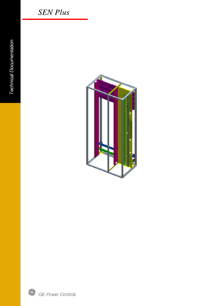
35.0 Control Centre Fixed Type
35.1 General Characteristics
The principle of the Control Centre is similar to the Power Centre.
The Control Centre based on its functional units is:
Fixed Type Control Centre
– Cubicle Type C
For detail information see chapter 6.0 of base Technical Documentation 917180_00.
The Control Centre is subdivided in three functional zones:
Busbar zone
Equipment zone
Cable zone
The busbar zone is located at the rear of the column and contains the main horizontal and
vertical busbar system. Internal separation sheets are dividing the busbar zone from the
equipment and cable zone and are protecting the operator against contact with hazardous
parts. The standard equipment zone for the Fixed Type control centre is separated from the
cable zone by means of the Vertical Form Separation for complete section.
Busbar zone
The busbar zone can be equipped with maximal 2 main busbar systems. Standard positions are
the top and the middle position.
Provisions are taken as standard to couple the main busbar system to the main busbar system
in adjacent columns from the front.
Equipment zone – Fixed Type Control Centre
The effective stocking density in the equipment zone is 80E (1E=25mm). The standard
separation to the busbar zone is realised by means Mounting Plate used to mount the breaker
The standard way of mounting the electrical components in the equipment zone is by means of
steel carriers .The Fixed units can be combined currents up to 1900A can be fixed directly into
the vertical riser system by rigid bus bar connection.
Cabling Zone
The cable zone is designed for fast and comfortable cabling. The 400mm width cable zone (for
column 1000mm width) or 600mm width cable zone (for column 1200mm width) is situated on
the right hand side from the equipment zone. Cable trays for servicing of all cables are provided
as standard.
Cables can either enter through the top or from the bottom, without increasing the total depth of
the switchboard. This is due to position of the main busbar in the rear of the column.
Enclosure
The maximum degree of protection is up to IP54 (according to IEC 60529).
The maximum form of internal separation is up to Form 4a (according up to IEC 60439-1)
Doors and covers are made out 2mm sheet steel, epoxy powder coated in standard colour
RAL 7035. The column can be equipped with optional panel bottom plate with a removable
aluminium gland plate.
3
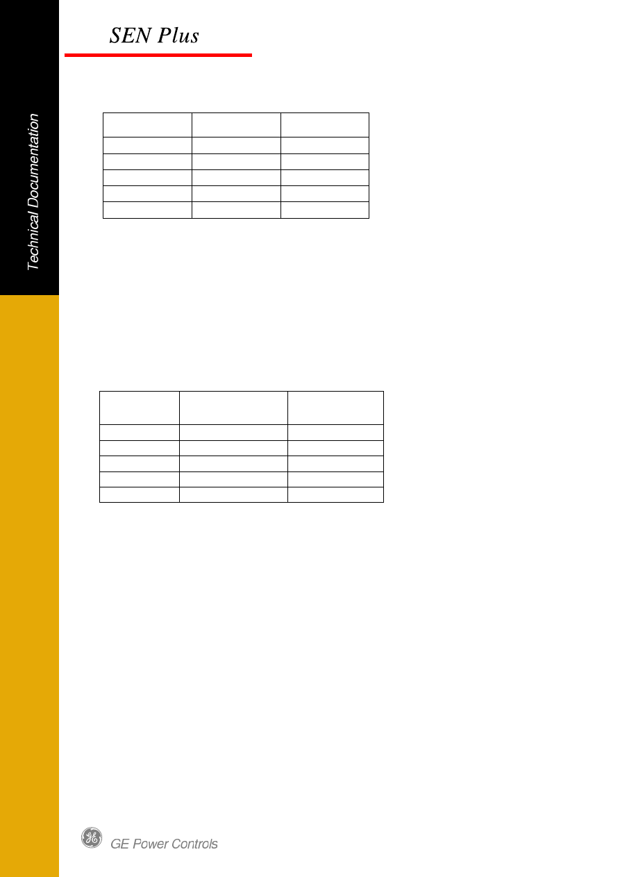
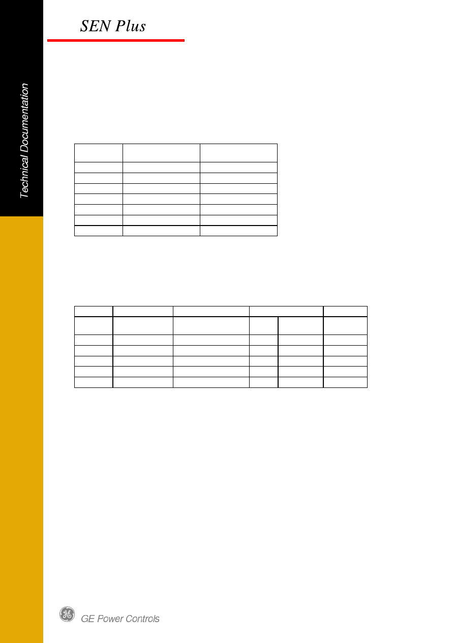
35.2 Arrangements
The height of the columns is 2200mm or 2000mm. Other dimensions could be supplied on
request.
Width
Depth
600 mm
Depth
800 mm
1000 mm
X
X
1200 mm
X
X
Fig. 1 Column arrangements Control Centre.
35.3 Module Arrangements
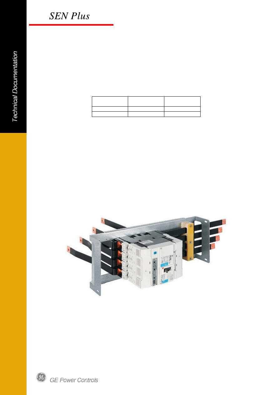
35.3.1 Module Fixed Type
The modules can be used for feeder (fuseless) applications. Modules are available to fix 3 and
4 pole version of MCCB type FD, FE and FG up to 630A. The line side of breaker to be
connected to VBB by mean of rigid copper or cables Customer is connecting the external
cables directly to the breakers terminals or to a specially provided busbars (as option).
The range of module sizes (height) varies from 6E up to 24E.
Fig.2 Module Fixed Type
4
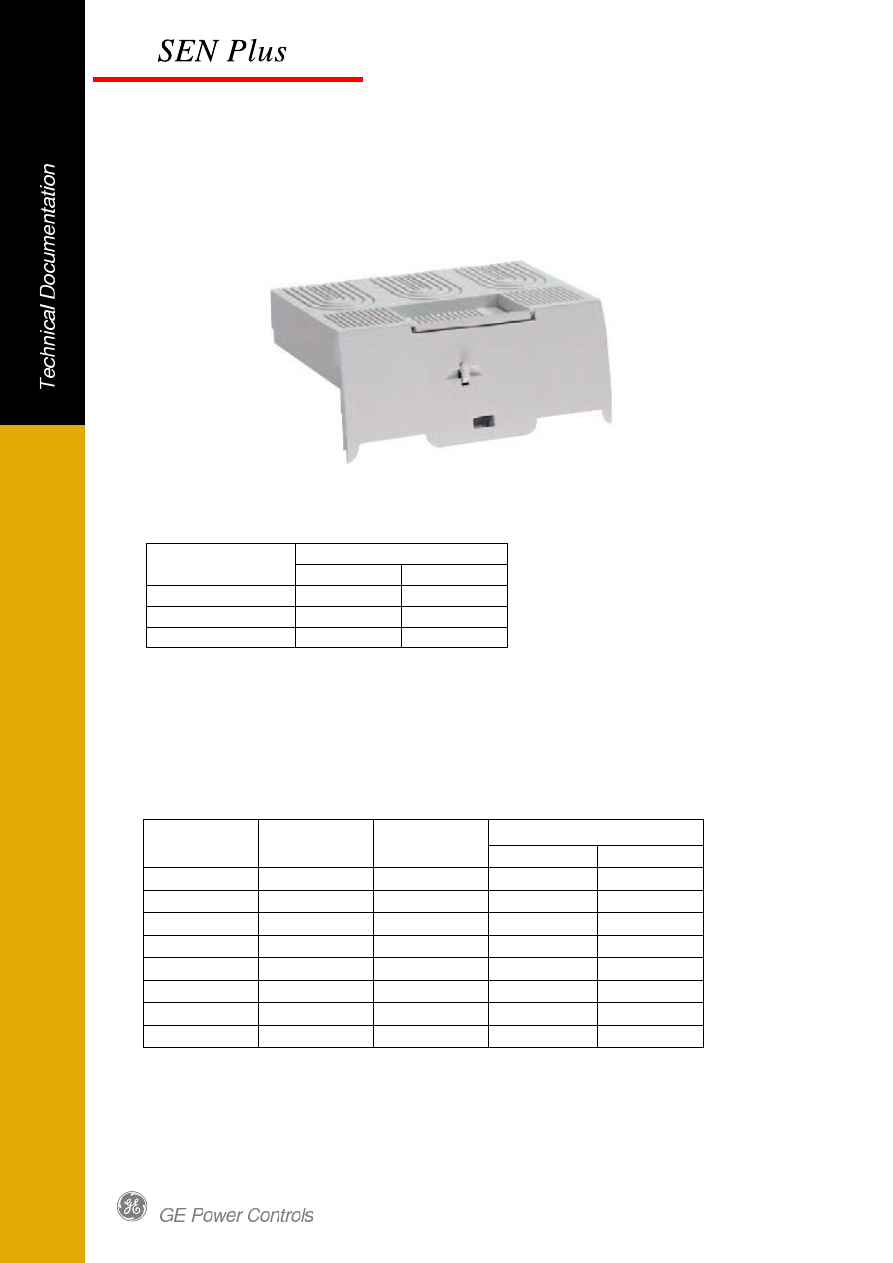
35.3.2 Terminal Shield Cover with Moulded Case Circuit Breaker
Use Breaker with Medium Terminal shields for FG and Long Terminal shields for FD and FE on
Load and Line Side.
Fig 3 Terminal Shield Cover
Ref No – Terminal Shields
Circuit breaker
3 pole
4 pole
Record Plus FD
430951
430954
Record Plus FE
432079
432082
Record Plus FG
432846
432849
Fig 4 Terminal Shield cover ref No
35.4 Rated current of main busbar system
The rated current of the main busbars varies from 1000A up to 4000 A and are based on blank
copper bars. Values for tinned copper on request.
Rated
Phases
Neutral
Depth of the panel
Current
600 mm
800 mm
A
mm
mm
1000
60x10
30x10
X
X
1250
60x10
30x10
X
X
1600
80x10
40x10
X
X
2000
100x10
40x10
X
X
2500
2/80x10
80x10
X
X
3200
2/100x10
80x10
X
X
4000
3/100x10
2/60x10
X
Fig. 5 Rated currents of the main horizontal busbars
5
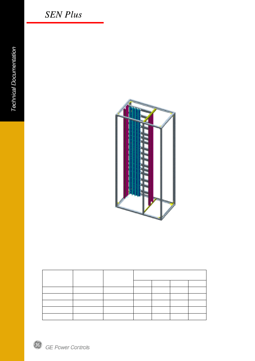
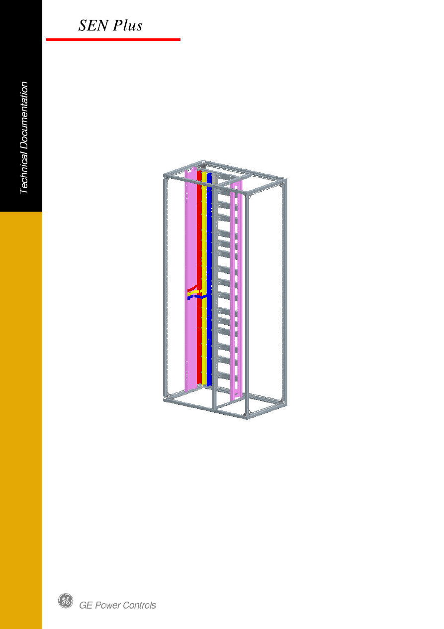
35.5 Vertical riser arrangements
The vertical riser system can be executed as a 3 or 4 pole design. The base is formed by an L
shape to which simply flat copper bus-bars can be added to upgrade the nominal current of the
system. For special environments the columns could be equipped with tinned copper bars as
option. The rated current is divided in 4 current steps variations from 850 up to 1900A.
The pole distance between the phases is 60mm.
The vertical busbar arrangements is Type C basically for feeder application in module technique
Fig. 6 Panel arrangement type C
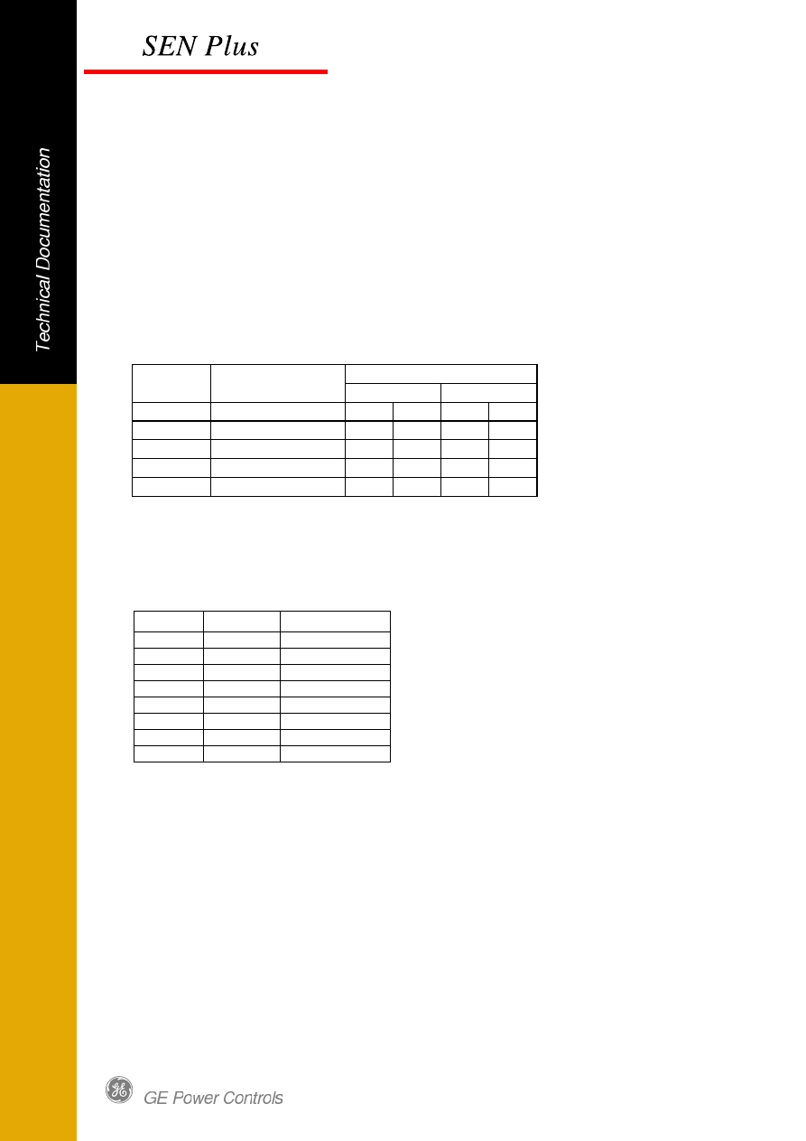
35.5.1 Rated currents and short circuit strength
Short circuit strength of the neutral conductor 60% of the value of the three phase short-
circuit withstand test.
Other values i.e. tinned copper on request.
Short time Current 1 second
Rated current Performance
Cross-section
Phases
30
50
65
80
A
mm
2
mm
2
kA
kA
kA
kA
(850)
L profile
375
x
1200
+ 1 layer
525
x
x
1550
+ 2 layer
675
x
x
x
1900
+ 3 layer
825
x
x
x
x
Fig. 7 Rated currents and short circuit strength of the vertical riser.
6
35.5.2 Cross-sectional area of neutral conductor N
The cross section of the neutral can be either half (standard) or full (optional) current carrying
capacity of the phases.
For 3 or 4 pole feeder applications in one column the cable compartment can be equipped with
an optional vertical neutral conductor
.
Fig. 8 Arrangement of N and PE vertical busbar (in cable compartment)
.
7
Figure 9 shows the cross section of the neutral conductor executed as separate conductor
positioned in cable compartment.
Rated current
Cross-section
Phases
Neutral Conductor
50%
Neutral Conductor
100% (optional)
A
mm
2
mm
mm
(850)
375
40x5
40x10
1200
525
40x5
50x10
1550
675
30x10
60x10
1900
825
40x10
80x10
Fig. 9 Cross section of neutral conductor
Figure 10 shows the cross section of the neutral as the 4th pole of the vertical riser system.
Rated current
Cross-section
Phases
Neutral Conductor
min. 50%
Neutral Conductor
100%
A
mm
2
mm
2
mm
2
(850)
375
375
375
1200
525
375
525
1550
675
375
675
1900
825
525
825
Fig.10 Cross section of neutral conductor
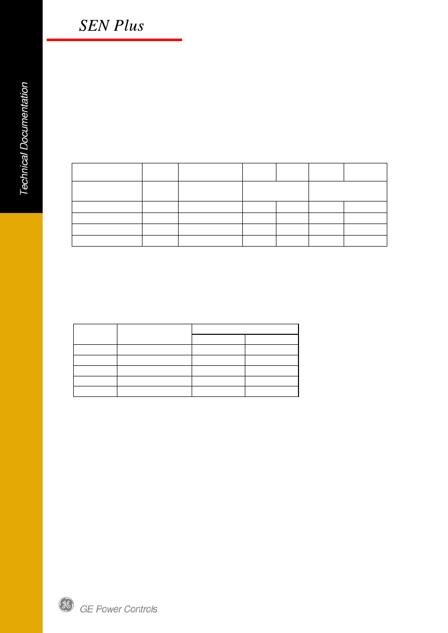
35.5.3 Cross-section of vertical protective conductor
The cross-section of protective conductors shall be determined in the following way:
in accordance to sub-clause 7.4.3.1.7a) of IEC standard 60439–1.
Cross sectional area of PE and PEN shall be not less than the value shown in the table
Rated current
Cross-section
Phases
Minimum Cross-
section of PE
Busbar
A
mm
2
mm²
mm
(850)
375
1/2
40x5
1200
525
200
40x5
1550
675
200
40x5
1900
825
1/4
30x10
Fig.11 Cross sections of the protective busbars as per IEC 60439-1 clause 7.4.3.1.7a.
Table is applicable for PEN-conductors, assumed the neutral currents do not exceed 30% of the
phase current
The standard arrangement of the PE conductor is at the rear side in the cable compartment
adjacent to the neutral conductor.
8
35.5.4 De-ratings
The maximum operation current of the vertical riser is related to
ambient temperature
protection degree of the enclosure
The copper bars are blank copper bars other values as tinned copper can be submitted on
request.
Ambient Temperature:
35°C
50°C
35°C
50°C
Rated
Current
Busbar
Degree of Protection
IP30
Degree of Protection
IP54
A
mm²
A
A
A
A
(850)
375
850
850
850
600
1200
525
1200
1000
850
650
1550
675
1550
1300
1150
800
1900
825
1900
1600
1350
900
Fig. 12 De-ratings of the vertical riser
Ambient temperature = temperature of the air surrounding the panels
35.5.5 Power loss
The power loss is based on the following
. dissipation at rated current
To enable the actual power loss the following formula is used
Actual Power Loss = (Actual Current / Rated Current)
2
x Rated Power Loss
Rated
Cross section
Power Loss
Current
Phases
at Rated Current
A
mm²
W
(850)
375
105
1200
525
160
1550
675
190
1900
825
233
Fig.13 Power losses of the vertical riser
.
9
35.6 Rigid busbar arrangement
The rigid busbar system can be executed as a 3 or 4 pole design. The rated current of the rigid
busbars are up to 630A and are based on blank copper bars. Busbar are insulated.
The rigid busbar arrangement is Type C basically for feeder application in module technique.
Fig. 14 Rigid Busbar arrangement
35.6.1 Cross-sectional area of Rigid Busbars
10
Cross-section area of rigid busbar are shown in fig 15
Rated current
Cross-section
Phases
Busbar
A
mm
2
mm
160
96
12x8
250
125
25x5
400
360
30x12
630
360
30x12
Fig.15 Cross sections of the rigid busbar
35.6.2 Power Loss
The power loss is based on the following
. dissipation at rated current
To enable the actual power loss the following formula is used
Actual Power Loss = (Actual Current / Rated Current)
2
x Rated Power Loss
Rated
Cross section
Power Loss
Current
Phases
at Rated Current
A
mm²
W
160
96
5
250
125
12
400
360
31
630
360
78
Fig.16 Power losses of the Rigid Busbar per meter
11
36.0 Standard configuration in Control Centre
A functional unit is a combination of electrical and mechanical components, which form together
an application. The standard functions of the control centre as of fixed type.
The Fixed modules units are fixed parts according to IEC standard 60439-1 sub clause 2.2.5:
The disconnections of fixed parts may require the disconnections of the complete ASSEMBLY
or parts of it.
In case of Fixed parts the connections of main circuits can only be established or broken when
the ASSEMBLY is dead. In general, removable and installation of Fixed parts required the use
of a tool.
GE advices always Switch off Mains while disconnection of Fixed Module
parts.
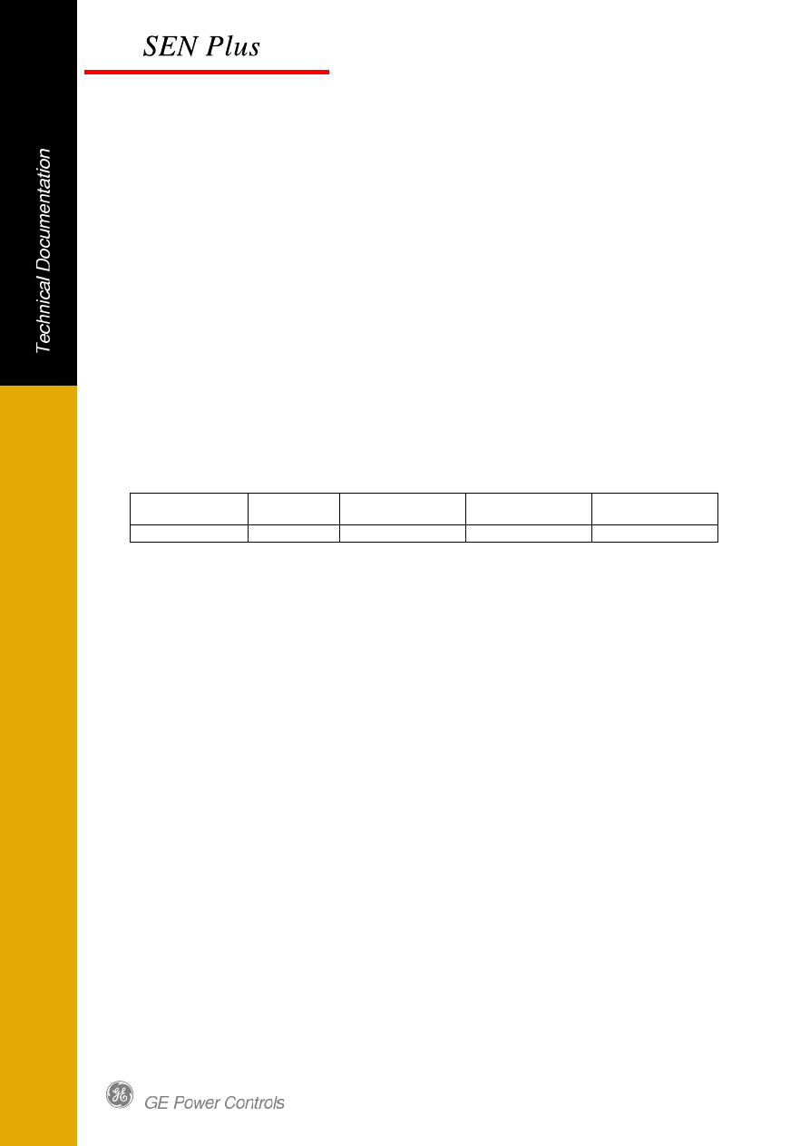
The electrical connections to the functional units are fixed or disconnectable as the table shows:
Connections:
Modules
type:
Disconnectable
Fixed
Withdrawable
Control circuits
Fixed Type
x
Fig.12 Standard connections
Disconnectable connection
a connection which is connected or disconnected by manual operation of the connected means
without a tool.
The supply side of the plug-in modules are executed with plug-in contacts.
Withdrawable connection
a connection which is connected or disconnected by bringing the functional unit into the
connected or disconnected situation.
Fixed connection
A connection, which is connected or disconnected by means of a tool.
Connections should be made either direct to the switchgear i.e. to the terminals of the thermal
overload relays (standard) or to a separate terminal strip (optional).
12
36.1 Feeder Arrangement
System integration is accomplished by using the new range of IEC 60947 designed and tested
rated industrial components of GE.
36.1.1 Feeder with Moulded Case Circuit Breaker
The arrangements are based on an operational voltage of 400V,500V and 690V and a breaking
capacity (Icu) of 50kA for the breakers.
Module size – Fixed Type
Current
Circuit breaker
3 pole
4 pole
A
type
mm
Height
mm
Height
up to 160
Record Plus FD160
200
8E
200
8E
up to 250
Record Plus FE250
250
10E
250
10E
up to 400
Record Plus FG400
250
10E
250
10E
up to 630
Record Plus FG630
250
10E
250
10E
Fig.17 Feeder arrangements with moulded case circuit breakers (400V,500V,690V)
36.1.3 Module sizes
The control centre fixed type modules sizes are specified in Table 18
Height
Fixed
Empty Module
5E
6E
x
8E
x
x
10E
x
x
12E
x
16E
18E
x
24E
x
Fig.18 Fixed Type Module size
13
36.1.4 De-ratings
The internal temperature of the columns and the derating is influenced by the following factors:
Power loss of the circuit breaker at service current
Panel dimensions
Type of erection (free standing or wall-mounted)
Protection degree of the enclosure
Internal partitions (hamper the free air circulation)
Ambient
Temperature:
Module
Ambient
Temperature:
35°C
50°C
35°C
50°C
Rated Current
Rated Current
With Ventilation
IP 30
Without Ventilation
A
A
A
A
A
A
FD-160
8E
160
144
122
122
80
FE-250
10E
250
225
175
175
125
FG-630
10E
630
567
441
441
315
Fig.19 Derating for module with Record Plus feeders for fully equipped tested panel configuration.
Free standing arrangement with main busbar system in the top position.
36.1.5 Weights
Module Weight – Fixed Type
Current
Circuit breaker
3 pole
4 pole
A
type
KG
KG
up to 160
Record Plus FD160
4.5
5.5
up to 250
Record Plus FE250
5.5
6.5
up to 400
Record Plus FG400
11.5
14.5
up to 630
Record Plus FG630
11.5
14.5
Fig.20 Weight of Module with Record Plus breaker
14
36.1.6 Power Loss
To enable the actual power loss the following formula is used
Actual Power Loss = (Actual Current / Rated Current)
2
x Rated Power Loss
Rated
Current
Circuit breaker
Power loss at rated
current
A
type
W
125
Record Plus FD160
18,8
160
Record Plus FD160
30,7
250
Record Plus FE250
45,0
400
Record Plus FG400
52,8
630
Record Plus FG630
119,1
800
Record Plus FK800
76,8
Fig. 21 Power loss standard feeders with MCCB.
36.1.7 Arrangement for External Connections
Current Circuit breaker
Cable Clamps
Bars or Cable lugs
Bars
Standard
connection
Bolt
Max. Width Thickness
A
type
mm
2
mm
mm
up to 160
FD160
1 x 2,5 - 95
M6
12
8
up to 250
FE250
1 x 16 -150
M8
25
5
up to 400
FG400
1 x 50 - 300
M10
32
12
up to 630
FG630
1 x 50 -300
M10
32
12
Fig. 22 Arrangement of external connections for Record Plus Breaker
15
36.2. Motor-starter arrangements
Full system integration is accomplished by using the new range of IEC 60947 designed and
tested range of industrial and control components of GE.
Customer uses empty modules 6E – 24E size, arranges and assembles apparatus by himself.
For detail information e.g. power loss, arrangement for external connections see
Base Technical Documentation - Chapter 6.0.
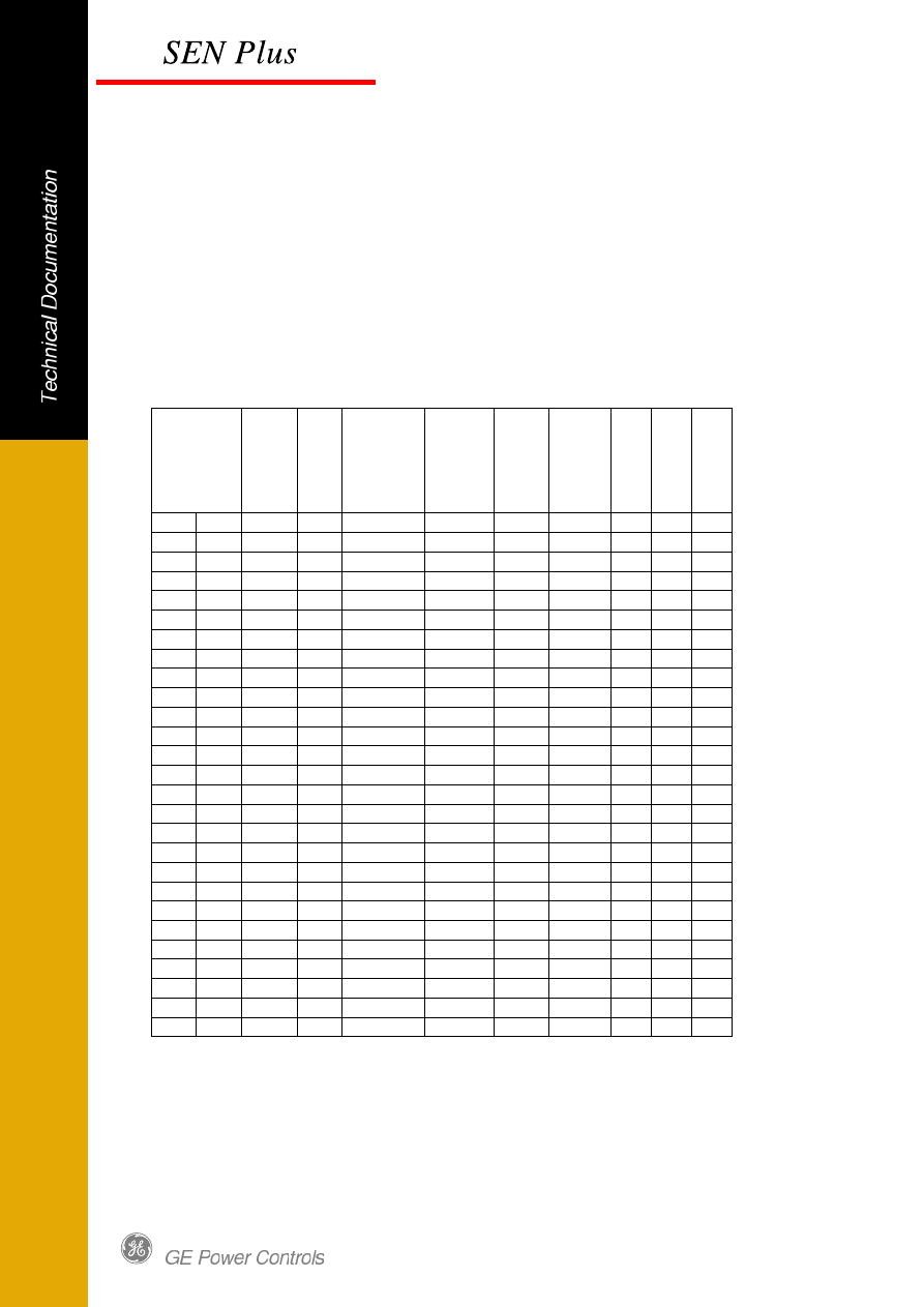
36.2.1 Direct on line starter with protection fuse DIN type
The motor-starters based on 3 pole arrangements at an operational voltage
of 400V 50 Hz. Type 2 Coordination (acc. IEC 60947-4-1) / AC3 category 50kA.
Motor load Current
Fuse
DIN
gL
Switch *) Contactor TOR
TOR
range
U
n
it
h
e
ig
h
t
M
o
d
u
le
s
iz
e
E
x
tr
a
M
o
d
u
le
s
iz
e
kW
HP
A
A
type
type
type
A
mm
0,25
0,33
0,9
2
DILOS 1
CL00
RT1F 0,65-1,1 150
6E
8E
0,37
0,5
1,13
4
DILOS 1
CL00
RT1G
1-1,5
150
6E
8E
0,55
0,75
1,6
4
DILOS 1
CL00
RT1H
1,3-1,9
150
6E
8E
0,75
1
2
4
DILOS 1
CL00
RT1J
1,8-2,7
150
6E
8E
1,1
1,5
2,6
4
DILOS 1
CL00
RT1K
2,5-4
150
6E
8E
1,5
2
3,5
6
DILOS 1
CL00
RT1K
2,5-4
150
6E
8E
2,2
3
5
10
DILOS 1
CL00
RT1L
4-6,3
150
6E
8E
3
4
7
16
DILOS 1
CL00
RT1N
8-12
150
6E
8E
4
5,5
9
20
DILOS 1
CL00
RT1N
8-12
150
6E
8E
5,5
7,5
12
25
DILOS 1
CL01
RT1N
8-12
150
6E
8E
7,5
10
16
35
DILOS 1
CL02
RT1P
10-16
150
6E
8E
11
15
22,5
35
DILOS 1
CL25
RT1U
21-26
150
6E
8E
15
20
30
50
DILOS 1
CL04
RT1V
25-32
150
6E
8E
18,5
25
37
63
DILOS 1
CL45
RT1W
30-40
150
6E
8E
22
30
44
63
DILOS 1
CL06
RT2G
42-55
200
8E
10E
30
40
60
80
FULOS 000
CL07
RT2H
54-65
250
10E
N/A
37
50
72
100 FULOS 000
CL08
RT2J
64-82
250
10E
N/A
45
60
85
125
FULOS 00
CL09
RT2L
78-97
300
12E
N/A
55
75
105
160
FULOS 1
CL10
RT2M
90-110
450 18E N/A
75
101
138
200
FULOS 1
CK75C
RT3E 110-140 600 24E N/A
90
121
170
200
FULOS 1
CK08C
RT3F 140-190 600 24E N/A
110
150
211
250
FULOS 2
CK85B
RT4P 175-280
N/A N/A
132
180
240
315
FULOS 2
CK09B
RT4P 175-280
N/A N/A
160
220
309
400
FULOS 3
CK95B
RT4R 200-310
N/A N/A
200
270
370
500
FULOS 3
CK10C
RT5C 250-400
N/A N/A
220
300
408
500
FULOS 3
CK10C
RT5D 315-500
N/A N/A
Fig. 23 Standardized fused motor-starter arrangements DOL (400V)
*) DILOS1 plus fuse base size 000/00 160A

16
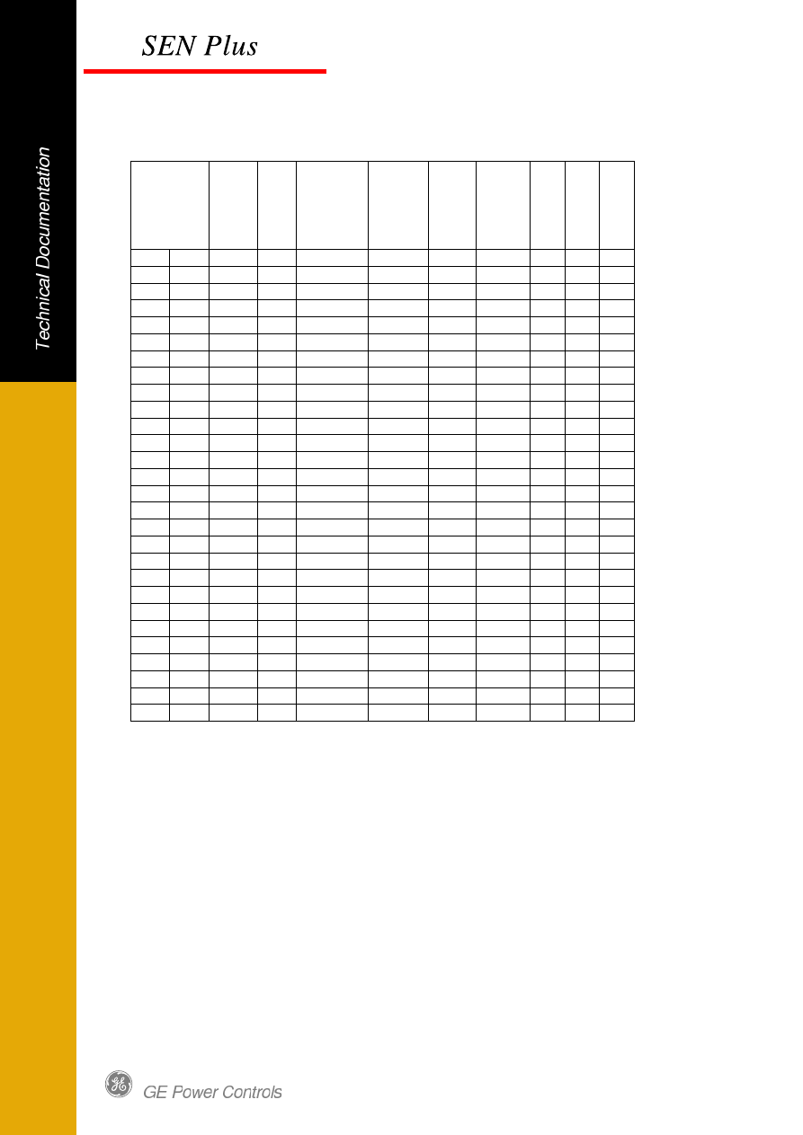
The motor-starters based on 3 pole arrangements at an operational voltage
of 500V 50 Hz. Type 2 Coordination (acc. IEC 60947-4-1) / AC3 category 50kA.
Motor load Current
Fuse
DIN
gL
Switch *) Contactor TOR
TOR
range
U
n
it
h
e
ig
h
t
M
o
d
u
le
s
iz
e
E
x
tr
a
M
o
d
u
le
s
iz
e
kW
HP
A
A
type
type
type
A
mm
0,25
0,33
0,66
4
DILOS 1
CL00
RT1D 0,4-0,65 150
6E
8E
0,37
0,5
0,9
4
DILOS 1
CL00
RT1F 0,65-1,1 150
6E
8E
0,55
0,75
1,2
4
DILOS 1
CL00
RT1G
1-1,5
150
6E
8E
0,75
1
1,5
6
DILOS 1
CL00
RT1H
1,3-1,9
150
6E
8E
1,1
1,5
2,1
6
DILOS 1
CL00
RT1J
1,8-2,7
150
6E
8E
1,5
2
2,6
6
DILOS 1
CL00
RT1K
2,5-4
150
6E
8E
2,2
3
3,8
10
DILOS 1
CL00
RT1K
2,5-4
150
6E
8E
3
4
5
16
DILOS 1
CL00
RT1L
4-6,3
150
6E
8E
4
5,5
6,5
25
DILOS 1
CL00
RT1N
8-12
150
6E
8E
5,5
7,5
9
25
DILOS 1
CL00
RT1N
8-12
150
6E
8E
7,5
10
12
25
DILOS 1
CL01
RT1N
8-12
150
6E
8E
11
15
17
40
DILOS 1
CL25
RT1S 14,5-18 150
6E
8E
15
20
23
50
DILOS 1
CL25
RT1U
21-26
150
6E
8E
18,5
25
28,5
50
DILOS 1
CL04
RT1V
25-32
150
6E
8E
22
30
33
80
DILOS 1
CL45
RT1W
30-40
150
6E
8E
30
40
45
100
DILOS 1
CL06
RT2G
42-55
200
8E
10E
37
50
55
125 FULOS 000
CL07
RT2H
54-65
250
10E
N/A
45
60
65
125 FULOS 000
CL08
RT2J
64-82
250
10E
N/A
55
75
80
200
FULOS 1
CL09
RT2L
78-97
450 18E N/A
75
101
105
200
FULOS 1
CK75C
RT3D
90-120
600 24E N/A
90
121
129
200
FULOS 1
CK75C
RT3E 110-140 600 24E N/A
110
150
156
250
FULOS 1
CK08C
RT3F 140-190 600 24E N/A
132
180
188
315
FULOS 2
CK85B
RT4P 175-280
N/A N/A
160
220
228
315
FULOS 2
CK09B
RT4P 175-280
N/A N/A
200
270
281
400
FULOS 3
CK95B
RT4R 200-310
N/A N/A
220
300
310
500
FULOS 3
CK10C
RT5C 250-400
N/A N/A
250
340
348
500
FULOS 3
CK10C
RT5D 315-500
N/A N/A
Fig. 24 Standardized fused motor-starter arrangements DOL (500V)
*) DILOS1 plus fuse base size 000/00 160A
17
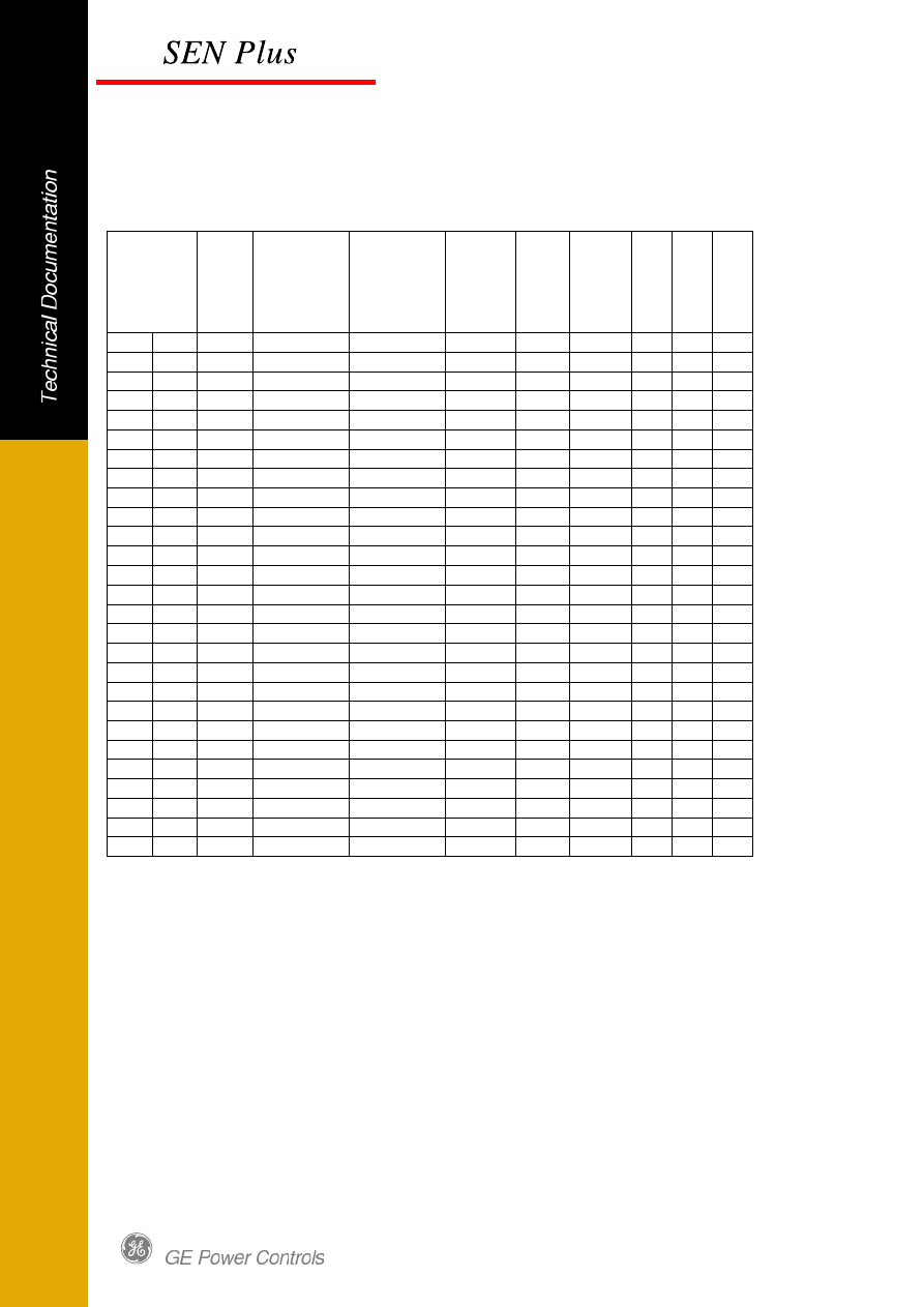
The motor-starters based on 3 pole arrangements at an operational voltage
of 690V 50 Hz. Type 2 Coordination (acc. IEC 60947-4-1) / AC3 category 50kA.
Motor load Current
Fuse
DIN
gL
Switch *) Contactor TOR
TOR
range
U
n
it
h
e
ig
h
t
M
o
d
u
le
s
iz
e
E
x
tr
a
M
o
d
u
le
s
iz
e
kW
HP
A
A
type
type
type
A
mm
0,25
0,33
0,46
4
DILOS 1
CL00
RT1D 0,4-0,65 150
6E
8E
0,37
0,5
0,7
4
DILOS 1
CL00
RT1F 0,65-1,1 150
6E
8E
0,55
0,75
0,8
4
DILOS 1
CL00
RT1F 0,65-1,1 150
6E
8E
0,75
1
1,1
4
DILOS 1
CL00
RT1G
1-1,5
150
6E
8E
1,1
1,5
1,6
6
DILOS 1
CL00
RT1H
1,3-1,9
150
6E
8E
1,5
2
2,2
6
DILOS 1
CL00
RT1J
1,8-2,7
150
6E
8E
2,2
3
3,1
6
DILOS 1
CL00
RT1K
2,5-4
150
6E
8E
3
4
4,2
10
DILOS 1
CL00
RT1L
4-6,3
150
6E
8E
4
5,5
4,9
16
DILOS 1
CL00
RT1L
4-6,3
150
6E
8E
5,5
7,5
6,7
20
DILOS 1
CL00
RT1M
5,5-8,5
150
6E
8E
7,5
10
9
25
DILOS 1
CL01
RT1N
8-12
150
6E
8E
11
15
13
40
DILOS 1
CL25
RT1P
10-16
150
6E
8E
15
20
17,5
50
DILOS 1
CL25
RT1S 14,5-18 150
6E
8E
18,5
25
23
50
DILOS 1
CL04
RT1U
21-26
150
6E
8E
22
30
25
63
DILOS 1
CL45
RT1V
25-32
150
6E
8E
30
40
33
63
DILOS 1
CL45
RT1W
30-40
150
6E
8E
37
50
42
80
DILOS 1
CL07
RT2E
30-43
200
8E
10E
45
60
49
100 FULOS 000
CL07
RT2G
42-55
250
10E
N/A
55
75
60
160
FULOS 00
CL09
RT2H
54-65
300
12E
N/A
75
101
82
200
FULOS 1
CK75C
RT3C
63-90
600
24E
N/A
90
121
98
160
FULOS 1
CK75C
RT3D
90-120
600
24E
N/A
110
150
118
200
FULOS 1
CK08C
RT3E 110-140 600
24E
N/A
132
180
140
250
FULOS 1
CK08C
RT3F 140-190
N/A N/A
160
220
175
250
FULOS 2
CK09B
RT4N 120-190
N/A N/A
200
270
214
315
FULOS 2
CK09B
RT4P 175-280
N/A N/A
220
300
230
400
FULOS 2
CK95B
RT4P 175-280
N/A N/A
250
340
270
400
FULOS 2
CK95B
RT4P 175-280
N/A N/A
Fig. 25 Standardized fused motor-starter arrangements DOL (690V)
*) DILOS1 plus fuse base size 000/00 160A
18
36.2.2 Direct on line starter with protection fuse BS type
The motor-starters based on 3 pole arrangements at an operational voltage
of 400V 50 Hz. Type 2 Coordination (acc. IEC 60947-4-1) / AC3 category 50kA.
Motor load Current
Fuse BS
Switch *)
Contactor TOR
TOR
range
U
n
it
h
e
ig
h
t
M
o
d
u
le
s
iz
e
E
x
tr
a
M
o
d
u
le
s
iz
e
kW
HP
A
type
type
type
type
A
mm
0,25
0,33
0,9
NIT4
DILOS 1
CL00
RT1F 0,65-1,1 150
6E
8E
0,37
0,5
1,13
NIT6
DILOS 1
CL00
RT1G
1-1,5
150
6E
8E
0,55
0,75
1,6
NIT6
DILOS 1
CL00
RT1H
1,3-1,9
150
6E
8E
0,75
1
2
NIT10
DILOS 1
CL00
RT1J
1,8-2,7
150
6E
8E
1,1
1,5
2,6
NIT10
DILOS 1
CL00
RT1J
1,8-2,7
150
6E
8E
1,5
2
3,5
NIT16
DILOS 1
CL00
RT1K
2,5-4
150
6E
8E
2,2
3
5
NIT16
DILOS 1
CL00
RT1L
4-6,3
150
6E
8E
3
4
7
NIT20
DILOS 1
CL00
RT1M
5,5-8,5
150
6E
8E
4
5,5
9
NIT20M25
DILOS 1
CL00
RT1N
8-12
150
6E
8E
5,5
7,5
12
TLA32M35
DILOS 1
CL01
RT1P
10-16
150
6E
8E
7,5
10
16
TLA32M40
DILOS 1
CL02
RT1S 14,5-18 150
6E
8E
11
15
22,5
TLA32M50
DILOS 1
CL25
RT1T 17,5-22 150
6E
8E
15
20
30
TIS63M80
DILOS 1
CL04
RT1V
25-32
150
6E
8E
18,5
25
37
TIS63M80
DILOS 1
CL45
RT1W
30-40
150
6E
8E
22
30
44
TIS63M80
DILOS 1
CL06
RT2G
42-55
200
8E
10E
30
40
60
OS100M125
FULOS 000
CL07
RT2H
54-65
250
10E N/A
37
50
72
OS100M125
FULOS 000
CL07
RT2J
64-82
250
10E N/A
45
60
85
TCP100M160
FULOS 00
CL08
RT2L
78-97
300
12E N/A
55
75
105
TCP100M160
FULOS 00
CL10
RT2M
90-110
300
12E N/A
75
101
135
TF200M250
FULOS 1
CK75C
RT3E 110-140 600
24E N/A
90
121
165
TF200M315
FULOS 1
CK08C
RT3F 140-190 600
24E N/A
110
150
211
TF200M315
FULOS 1
CK85B
RT4P 175-280
N/A N/A
132
180
240
TKF315
FULOS 2
CK09B
RT4P 175-280
N/A N/A
160
220
309
TKF315M355
FULOS 2
CK95B
RT4R 200-310
N/A N/A
200
270
370
TM400
FULOS 3
CK10C
RT5C 250-400
N/A N/A
220
300
408
TM450
FULOS 3
CK10C
RT5D 315-500
N/A N/A
Fig. 26 Standardized fused motor-starter arrangements DOL (400V)
*) DILOS1 plus fuse base:
RS20H up to 4kW
RS32H 5,5 to 11kW
RS63H 15 to 22kW
19
36.2.3 Direct on line starter with circuit breaker protection
The motor-starters based on 3 pole arrangements at an operational voltage
of 400V 50 Hz. Type 2 Coordination (acc. IEC 60947-4-1) / AC3 category 50kA.
Motor load Current
T
h
e
rm
a
l
c
u
rr
e
n
t
b
re
a
k
e
r
ra
n
g
e
Circuit
breaker
Contactor TOR
TOR
range
U
n
it
h
e
ig
h
t
M
o
d
u
le
s
iz
e
E
x
tr
a
M
o
d
u
le
s
iz
e
kW
HP
A
A
type
type
type
A
mm
0,25
0,33
0,9
0,63-1 GPS1BHAE
CL00
150
6E
8E
0,37
0,5
1,13
1-1,6
GPS1BHAF
CL00
150
6E
8E
0,55
0,75
1,6
1-1,7
GPS1BHAF
CL00
150
6E
8E
0,75
1
2
0,6-2,5 GPS1BHAG
CL00
150
6E
8E
1,1
1,5
2,6
2,5-4
GPS1BHAH
CL01
150
6E
8E
1,5
2
3,5
2,5-4
GPS1BHAH
CL01
150
6E
8E
2,2
3
5
4-6,3
GPS1BHAJ
CL02
150
6E
8E
3
4
7
6,3-10 GPS1BHAK
CL25
150
6E
8E
4
5,5
9
6,3-10 GPS1BHAK
CL25
150
6E
8E
5,5
7,5
12
9-13
GPS1BHAL
CL25
150
6E
8E
7,5
10
16
11-16 GPS1BHAM
CL25
150
6E
8E
11
15
22,5
19-25 GPS1BHAP
CL25
150
6E
8E
15
20
30
24-32 GPS2BHAR
CL04
150
6E
8E
18,5
25
37
28-40 GPS2BHAS
CL45
150
6E
8E
22
30
44
35-50 GPS2BHAT
CL06
150
6E
8E
30
40
60
45-63 GPS2BHAU
CL07
150
6E
8E
37
50
72
80
FDH160
CL08
RT2J
64-82
300 12E N/A
45
60
85
100
FDH160
CK85B
RT2L
78-97
450 18E N/A
55
75
105
125
FEH160
CK85B
RT2M
90-110
450 18E
N/A
75
101
138
160
FEH160
CK95B
RT3E 110-140 450 18E
N/A
90
121
170
250
FEH250
CK95B
RT4N 120-190 600 24E N/A
110
150
211
250
FEH250
CK10C
RT4R 200-310 600 24E N/A
132
180
240
250
FEH250
CK10C
RT4R 200-310 600 24E N/A
160
220
309
350
FGH400
CK10C
RT5C 250-400
N/A N/A
200
270
370
500
FGH630
CK10C
RT5D 315-500
N/A N/A
220
300
408
500
FGH630
CK10C
RT5D 315-500
N/A N/A
Fig. 27 Standardized fuseless motor-starter arrangements DOL (400V)
20
The motor-starters based on 3 pole arrangements at an operational voltage
of 500V 50 Hz. Type 2 Coordination (acc. IEC 60947-4-1) / AC3 category 50kA.
Motor load Current
T
h
e
rm
a
l
c
u
rr
e
n
t
b
re
a
k
e
r
ra
n
g
e
Circuit
breaker
Contactor TOR
TOR
range
U
n
it
h
e
ig
h
t
M
o
d
u
le
s
iz
e
E
x
tr
a
M
o
d
u
le
s
iz
e
kW
HP
A
A
type
type
type
A
mm
0,25
0,33
0,66
0,63-1 GPS1BHAE
CL00
150
6E
8E
0,37
0,5
0,9
0,63-1 GPS1BHAE
CL00
150
6E
8E
0,55
0,75
1,2
1-1,6
GPS1BHAF
CL00
150
6E
8E
0,75
1
1,5
1-1,6
GPS1BHAF
CL00
150
6E
8E
1,1
1,5
2,1
1,6-2,5 GPS1BHAG
CL00
150
6E
8E
1,5
2
2,6
2,5-4
GPS1BHAH
CL25
150
6E
8E
2,2
3
3,8
2,5-4
GPS1BHAH
CL25
150
6E
8E
3
4
5
4-6,3
GPS1BHAJ
CL25
150
6E
8E
4
5,5
6,5
6,3-10 GPS1BHAK
CL25
150
6E
8E
5,5
7,5
9
6,3-10 GPS1BHAK
CL25
150
6E
8E
7,5
10
12
9-13
GPS1BHAL
CL25
150
6E
8E
11
15
17
14-20 GPS1BHAN
CL25
150
6E
8E
15
20
23
19-25 GPS1BHAP
CL04
150
6E
8E
18,5
25
28,5
24-32 GPS1BHAR
CL04
150
6E
8E
22
30
33
28-40 GPS2BHAS
CL06
150
6E
8E
30
40
45
35-50 GPS2BHAT
CL06
150
6E
8E
37
50
55
45-63 GPS2BHAU
CL07
150
6E
8E
45
60
65
80
FEH160
CL07
RT2J
64-82
300 12E N/A
55
75
80
100
FEH160
CK75C
RT2L
78-97
450 18E
N/A
75
101
105
100
FEH160
CK85B
RT2M
90-110
450 18E
N/A
90
121
129
125
FEH160
CK85B
RT3E 110-140 450 18E N/A
110
150
156
160
FEH160
CK95B
RT3F 140-190 450 18E N/A
132
180
188
250
FEH250
CK95B
RT4N 120-190 600 24E N/A
160
220
228
250
FEH250
CK10C
RT4R 200-310 600 24E N/A
200
270
281
250
FGH400
CK10C
RT4R 200-310
N/A N/A
220
300
310
400
FGH400
CK10C
RT5C 250-400
N/A N/A
250
340
348
400
FGH400
CK10C
RT5C 250-400
N/A N/A
Fig. 28 Standardized fuseless motor-starter arrangements DOL (500V)
21
The motor-starters based on 3 pole arrangements at an operational voltage
of 690V 50 Hz. Type 2 Coordination (acc. IEC 60947-4-1) / AC3 category 50kA.
Motor load Current
T
h
e
rm
a
l
c
u
rr
e
n
t
b
re
a
k
e
r
ra
n
g
e
Circuit
breaker
Contactor TOR
TOR
range
U
n
it
h
e
ig
h
t
M
o
d
u
le
s
iz
e
E
x
tr
a
M
o
d
u
le
s
iz
e
kW
HP
A
A
type
type
type
A
mm
4
5,5
4,9
7
FEL160
CL03
RT12L
4-6.3
300 12E N/A
5,5
7,5
6,7
7
FEL160
CL03
RT1M
5.5-8.5
300 12E N/A
7,5
10
9
12,5
FEL160
CL07
RT2A
7.6-15
300 12E N/A
11
15
13
20
FEL160
CL07
RT2B 12.5-19 300 12E N/A
15
20
17,5
20
FEL160
CL07
RT2B 12.5-19 300 12E N/A
18,5
25
23
30
FEL160
CL09
RT2C 18.5-25 300 12E N/A
22
30
25
30
FEL160
CL09
RT2D
24-32
300 12E N/A
30
40
33
50
FEL160
CL09
RT2E
30-43
300 12E N/A
37
50
42
50
FEL160
CL09
RT2G
42-55
300 12E N/A
45
60
49
50
FEL160
CL09
RT2G
42-55
300 12E N/A
55
75
60
80
FEL160
CL09
RT2H
54-65
300 12E N/A
75
101
82
100
FEL160
CK75C
RT2L
78-97
450 18E N/A
90
121
98
100
FEL160
CK85B
RT2M
90-110
450 18E N/A
110
150
118
125
FEL160
CK85B
RT3E 110-140 450 18E N/A
132
180
140
160
FEL160
CK95B
RT3F 140-190 450 18E N/A
160
220
175
250
FEL250
CK95B
RT4N 120-190 600 24E N/A
200
270
214
250
FEL250
CK10C
RT4R 200-310 600 24E N/A
220
300
230
250
FEL250
CK10C
RT4R 200-310 600 24E N/A
250
340
270
400
FGL400
CK10C
RT5C 250-400
N/A N/A
Fig. 29 Standardized fuseless motor-starter arrangements DOL (690V)

22
36.2.4 Reverse motor-starter with protection fuse DIN type
The motor-starters based on 3 pole arrangements at an operational voltage
of 400V 50 Hz. Type 2 Coordination (acc. IEC 60947-4-1) / AC3 category 50kA.
Motor load Current
Fuse
DIN
gL
Switch *) Contactor TOR
TOR
range
U
n
it
h
e
ig
h
t
M
o
d
u
le
s
iz
e
E
x
tr
a
M
o
d
u
le
s
iz
e
kW
HP
A
A
type
type
type
A
mm
0,25
0,33
0,9
2
DILOS 1
CL00
RT1F 0,65-1,1 200
8E
10E
0,37
0,5
1,13
4
DILOS 1
CL00
RT1G
1-1,5
200
8E
10E
0,55
0,75
1,6
4
DILOS 1
CL00
RT1H
1,3-1,9
200
8E
10E
0,75
1
2
4
DILOS 1
CL00
RT1J
1,8-2,7
200
8E
10E
1,1
1,5
2,6
4
DILOS 1
CL00
RT1K
2,5-4
200
8E
10E
1,5
2
3,5
6
DILOS 1
CL00
RT1K
2,5-4
200
8E
10E
2,2
3
5
10
DILOS 1
CL00
RT1L
4-6,3
200
8E
10E
3
4
7
16
DILOS 1
CL00
RT1N
8-12
200
8E
10E
4
5,5
9
20
DILOS 1
CL00
RT1N
8-12
200
8E
10E
5,5
7,5
12
25
DILOS 1
CL01
RT1N
8-12
200
8E
10E
7,5
10
16
35
DILOS 1
CL02
RT1P
10-16
200
8E
10E
11
15
22,5
35
DILOS 1
CL25
RT1U
21-26
200
8E
10E
15
20
30
50
DILOS 1
CL04
RT1V
25-32
200
8E
10E
18,5
25
37
63
DILOS 1
CL45
RT1W
30-40
200
8E
10E
22
30
44
63
DILOS 1
CL06
RT2G
42-55
250
10E
N/A
30
40
60
80
FULOS 000
CL07
RT2H
54-65
300
12E
N/A
37
50
72
100 FULOS 000
CL08
RT2J
64-82
300
12E
N/A
45
60
85
125
FULOS 00
CL09
RT2L
78-97
300
12E
N/A
55
75
105
160
FULOS 1
CL10
RT2M
90-110
600
24E
N/A
75
101
138
200
FULOS 1
CK75C
RT3E 110-140
N/A N/A
90
121
170
200
FULOS 1
CK08C
RT3F 140-190
N/A N/A
110
150
211
250
FULOS 2
CK85B
RT4P 175-280
N/A N/A
132
180
240
315
FULOS 2
CK09B
RT4P 175-280
N/A N/A
160
220
309
400
FULOS 3
CK95B
RT4R 200-310
N/A N/A
200
270
370
500
FULOS 3
CK10C
RT5C 250-400
N/A N/A
220
300
408
500
FULOS 3
CK10C
RT5D 315-500
N/A N/A
Fig. 30 Standardized fused motor-starter arrangements reverse (400V)
*) DILOS1 plus fuse base size 000/00 160A

23
The motor-starters based on 3 pole arrangements at an operational voltage
of 500V 50 Hz. Type 2 Coordination (acc. IEC 60947-4-1) / AC3 category 50kA.
Motor load Current
Fuse
DIN
gL
Switch *) Contactor TOR
TOR
range
U
n
it
h
e
ig
h
t
M
o
d
u
le
s
iz
e
E
x
tr
a
M
o
d
u
le
s
iz
e
kW
HP
A
A
type
type
type
A
mm
0,25
0,33
0,66
4
DILOS 1
CL00
RT1D 0,4-0,65 200
8E
10E
0,37
0,5
0,9
4
DILOS 1
CL00
RT1F 0,65-1,1 200
8E
10E
0,55
0,75
1,2
4
DILOS 1
CL00
RT1G
1-1,5
200
8E
10E
0,75
1
1,5
6
DILOS 1
CL00
RT1H
1,3-1,9
200
8E
10E
1,1
1,5
2,1
6
DILOS 1
CL00
RT1J
1,8-2,7
200
8E
10E
1,5
2
2,6
6
DILOS 1
CL00
RT1K
2,5-4
200
8E
10E
2,2
3
3,8
10
DILOS 1
CL00
RT1K
2,5-4
200
8E
10E
3
4
5
16
DILOS 1
CL00
RT1L
4-6,3
200
8E
10E
4
5,5
6,5
25
DILOS 1
CL00
RT1N
8-12
200
8E
10E
5,5
7,5
9
25
DILOS 1
CL00
RT1N
8-12
200
8E
10E
7,5
10
12
25
DILOS 1
CL01
RT1N
8-12
200
8E
10E
11
15
17
40
DILOS 1
CL25
RT1S 14,5-18 200
8E
10E
15
20
23
50
DILOS 1
CL25
RT1U
21-26
200
8E
10E
18,5
25
28,5
50
DILOS 1
CL04
RT1V
25-32
200
8E
10E
22
30
33
80
DILOS 1
CL45
RT1W
30-40
200
8E
10E
30
40
45
100
DILOS 1
CL06
RT2G
42-55
250
10E
N/A
37
50
55
125 FULOS 000
CL07
RT2H
54-65
300
12E
N/A
45
60
65
125 FULOS 000
CL08
RT2J
64-82
300
12E
N/A
55
75
80
200
FULOS 1
CL09
RT2L
78-97
600
24E
N/A
75
101
105
200
FULOS 1
CK75C
RT3D
90-120
N/A N/A
90
121
129
200
FULOS 1
CK75C
RT3E 110-140
N/A N/A
110
150
156
250
FULOS 1
CK08C
RT3F 140-190
N/A N/A
132
180
188
315
FULOS 2
CK85B
RT4P 175-280
N/A N/A
160
220
228
315
FULOS 2
CK09B
RT4P 175-280
N/A N/A
200
270
281
400
FULOS 3
CK95B
RT4R 200-310
N/A N/A
220
300
310
500
FULOS 3
CK10C
RT5C 250-400
N/A N/A
250
340
348
500
FULOS 3
CK10C
RT5D 315-500
N/A N/A
Fig. 31 Standardized fused motor-starter arrangements reverse (500V)
*) DILOS1 plus fuse base size 000/00 160A

24
The motor-starters based on 3 pole arrangements at an operational voltage
of 690V 50 Hz. Type 2 Coordination (acc. IEC 60947-4-1) / AC3 category 50kA.
Motor load Current
Fuse
DIN
gL
Switch *) Contactor TOR
TOR
range
U
n
it
h
e
ig
h
t
M
o
d
u
le
s
iz
e
E
x
tr
a
M
o
d
u
le
s
iz
e
kW
HP
A
A
type
type
type
A
mm
0,25
0,33
0,46
4
DILOS 1
CL00
RT1D 0,4-0,65 200
8E
10E
0,37
0,5
0,7
4
DILOS 1
CL00
RT1F 0,65-1,1 200
8E
10E
0,55
0,75
0,8
4
DILOS 1
CL00
RT1F 0,65-1,1 200
8E
10E
0,75
1
1,1
4
DILOS 1
CL00
RT1G
1-1,5
200
8E
10E
1,1
1,5
1,6
6
DILOS 1
CL00
RT1H
1,3-1,9
200
8E
10E
1,5
2
2,2
6
DILOS 1
CL00
RT1J
1,8-2,7
200
8E
10E
2,2
3
3,1
6
DILOS 1
CL00
RT1K
2,5-4
200
8E
10E
3
4
4,2
10
DILOS 1
CL00
RT1L
4-6,3
200
8E
10E
4
5,5
4,9
16
DILOS 1
CL00
RT1L
4-6,3
200
8E
10E
5,5
7,5
6,7
20
DILOS 1
CL00
RT1M
5,5-8,5
200
8E
10E
7,5
10
9
25
DILOS 1
CL01
RT1N
8-12
200
8E
10E
11
15
13
40
DILOS 1
CL25
RT1P
10-16
200
8E
10E
15
20
17,5
50
DILOS 1
CL25
RT1S 14,5-18 200
8E
10E
18,5
25
23
50
DILOS 1
CL04
RT1U
21-26
200
8E
10E
22
30
25
63
DILOS 1
CL45
RT1V
25-32
200
8E
10E
30
40
33
63
DILOS 1
CL45
RT1W
30-40
200
8E
10E
37
50
42
80
DILOS 1
CL07
RT2E
30-43
250
10E
N/A
45
60
49
100 FULOS 000
CL07
RT2G
42-55
300
12E
N/A
55
75
60
160
FULOS 00
CL09
RT2H
54-65
300
12E
N/A
75
101
82
200
FULOS 1
CK75C
RT3C
63-90
N/A N/A
90
121
98
160
FULOS 1
CK75C
RT3D
90-120
N/A N/A
110
150
118
200
FULOS 1
CK08C
RT3E 110-140
N/A N/A
132
180
140
250
FULOS 1
CK08C
RT3F 140-190
N/A N/A
160
220
175
250
FULOS 2
CK09B
RT4N 120-190
N/A N/A
200
270
214
315
FULOS 2
CK09B
RT4P 175-280
N/A N/A
220
300
230
400
FULOS 2
CK95B
RT4P 175-280
N/A N/A
250
340
270
400
FULOS 2
CK95B
RT4P 175-280
N/A N/A
Fig. 32 Standardized fused motor-starter arrangements reverse (690V)
*) DILOS1 plus fuse base size 000/00 160A

25
36.2.5 Reverse motor-starter with protection fuse BS type
The motor-starters based on 3 pole arrangements at an operational voltage
of 400V 50 Hz. Type 2 Coordination (acc. IEC 60947-4-1) / AC3 category 50kA.
Motor load Current
Fuse BS
Switch *)
Contactor TOR
TOR
range
U
n
it
h
e
ig
h
t
M
o
d
u
le
s
iz
e
E
x
tr
a
M
o
d
u
le
s
iz
e
kW
HP
A
type
type
type
type
A
mm
0,25
0,33
0,9
NIT4
DILOS 1
CL00
RT1F 0,65-1,1 200
8E
10E
0,37
0,5
1,13
NIT6
DILOS 1
CL00
RT1G
1-1,5
200
8E
10E
0,55
0,75
1,6
NIT6
DILOS 1
CL00
RT1H
1,3-1,9
200
8E
10E
0,75
1
2
NIT10
DILOS 1
CL00
RT1J
1,8-2,7
200
8E
10E
1,1
1,5
2,6
NIT10
DILOS 1
CL00
RT1J
1,8-2,7
200
8E
10E
1,5
2
3,5
NIT16
DILOS 1
CL00
RT1K
2,5-4
200
8E
10E
2,2
3
5
NIT16
DILOS 1
CL00
RT1L
4-6,3
200
8E
10E
3
4
7
NIT20
DILOS 1
CL00
RT1M
5,5-8,5
200
8E
10E
4
5,5
9
NIT20M25
DILOS 1
CL00
RT1N
8-12
200
8E
10E
5,5
7,5
12
TLA32M35
DILOS 1
CL01
RT1P
10-16
200
8E
10E
7,5
10
16
TLA32M40
DILOS 1
CL02
RT1S 14,5-18 200
8E
10E
11
15
22,5
TLA32M50
DILOS 1
CL25
RT1T 17,5-22 200
8E
10E
15
20
30
TIS63M80
DILOS 1
CL04
RT1V
25-32
200
8E
10E
18,5
25
37
TIS63M80
DILOS 1
CL45
RT1W
30-40
200
8E
10E
22
30
44
TIS63M80
DILOS 1
CL06
RT2G
42-55
250
10E
N/A
30
40
60
OS100M125
FULOS 000
CL07
RT2H
54-65
300
12E
N/A
37
50
72
OS100M125
FULOS 000
CL07
RT2J
64-82
300
12E
N/A
45
60
85
TCP100M160
FULOS 00
CL08
RT2L
78-97
300
12E
N/A
55
75
105
TCP100M160
FULOS 00
CL10
RT2M
90-110
300
12E
N/A
75
101
135
TF200M250
FULOS 1
CK75C
RT3E 110-140
N/A N/A
90
121
165
TF200M315
FULOS 1
CK08C
RT3F 140-190
N/A N/A
110
150
211
TF200M315
FULOS 1
CK85B
RT4P 175-280
N/A N/A
132
180
240
TKF315
FULOS 2
CK09B
RT4P 175-280
N/A N/A
160
220
309
TKF315M355
FULOS 2
CK95B
RT4R 200-310
N/A N/A
200
270
370
TM400
FULOS 3
CK10C
RT5C 250-400
N/A N/A
220
300
408
TM450
FULOS 3
CK10C
RT5D 315-500
N/A N/A
Fig. 33 Standardized fused motor-starter arrangements reverse (400V)
*) DILOS1 plus fuse base:
RS20H up to 4kW
RS32H 5,5 to 11kW
RS63H 15 to 22kW

26
36.2.6 Reverse motor-starter with circuit breaker protection
The motor-starters based on 3 pole arrangements at an operational voltage
of 400V 50 Hz. Type 2 Coordination (acc. IEC 60947-4-1) / AC3 category 50kA.
Motor load Current
T
h
e
rm
a
l
c
u
rr
e
n
t
b
re
a
k
e
r
ra
n
g
e
Circuit
breaker
Contactor TOR
TOR
range
U
n
it
h
e
ig
h
t
M
o
d
u
le
s
iz
e
E
x
tr
a
M
o
d
u
le
s
iz
e
kW
HP
A
A
type
type
type
A
mm
0,25
0,33
0,9
0,63-1 GPS1BHAE
CL00
150
6E
8E
0,37
0,5
1,13
1-1,6
GPS1BHAF
CL00
150
6E
8E
0,55
0,75
1,6
1-1,7
GPS1BHAF
CL00
150
6E
8E
0,75
1
2
0,6-2,5 GPS1BHAG
CL00
150
6E
8E
1,1
1,5
2,6
2,5-4
GPS1BHAH
CL01
150
6E
8E
1,5
2
3,5
2,5-4
GPS1BHAH
CL01
150
6E
8E
2,2
3
5
4-6,3
GPS1BHAJ
CL02
150
6E
8E
3
4
7
6,3-10 GPS1BHAK
CL25
150
6E
8E
4
5,5
9
6,3-10 GPS1BHAK
CL25
150
6E
8E
5,5
7,5
12
9-13
GPS1BHAL
CL25
150
6E
8E
7,5
10
16
11-16 GPS1BHAM
CL25
150
6E
8E
11
15
22,5
19-25 GPS1BHAP
CL25
150
6E
8E
15
20
30
24-32 GPS2BHAR
CL04
150
6E
8E
18,5
25
37
28-40 GPS2BHAS
CL45
200
8E
10E
22
30
44
35-50 GPS2BHAT
CL06
200
8E
10E
30
40
60
45-63 GPS2BHAU
CL07
200
8E
10E
37
50
72
80
FDH160
CL07
RT2J
64-82
300 12E
N/A
45
60
85
100
FDH160
CK85B
RT2L
78-97
600 24E
N/A
55
75
105
125
FEH160
CK85B
RT2M
90-110
600
24E
N/A
75
101
138
160
FEH160
CK95B
RT3E 110-140 600
24E
N/A
90
121
170
250
FEH250
CK95B
RT4N 120-190
N/A
N/A
110
150
211
250
FEH250
CK10C
RT4R 200-310
N/A
N/A
132
180
240
250
FEH250
CK10C
RT4R 200-310
N/A
N/A
160
220
309
350
FGH400
CK10C
RT5C 250-400
N/A
N/A
200
270
370
500
FGH630
CK10C
RT5D 315-500
N/A
N/A
220
300
408
500
FGH630
CK10C
RT5D 315-500
N/A
N/A
Fig. 34 Standardized fuseless motor-starter arrangements reverse (400V)

27
The motor-starters based on 3 pole arrangements at an operational voltage
of 500V 50 Hz. Type 2 Coordination (acc. IEC 60947-4-1) / AC3 category 50kA.
Motor load Current
T
h
e
rm
a
l
c
u
rr
e
n
t
b
re
a
k
e
r
ra
n
g
e
Circuit
breaker
Contactor TOR
TOR
range
U
n
it
h
e
ig
h
t
M
o
d
u
le
s
iz
e
E
x
tr
a
M
o
d
u
le
s
iz
e
kW
HP
A
A
type
type
type
A
mm
0,25
0,33
0,66
0,63-1 GPS1BHAE
CL00
150
6E
8E
0,37
0,5
0,9
0,63-1 GPS1BHAE
CL00
150
6E
8E
0,55
0,75
1,2
1-1,6
GPS1BHAF
CL00
150
6E
8E
0,75
1
1,5
1-1,6
GPS1BHAF
CL00
150
6E
8E
1,1
1,5
2,1
1,6-2,5 GPS1BHAG
CL00
150
6E
8E
1,5
2
2,6
2,5-4
GPS1BHAH
CL25
150
6E
8E
2,2
3
3,8
2,5-4
GPS1BHAH
CL25
150
6E
8E
3
4
5
4-6,3
GPS1BHAJ
CL25
150
6E
8E
4
5,5
6,5
6,3-10 GPS1BHAK
CL25
150
6E
8E
5,5
7,5
9
6,3-10 GPS1BHAK
CL25
150
6E
8E
7,5
10
12
9-13
GPS1BHAL
CL25
150
6E
8E
11
15
17
14-20 GPS1BHAN
CL25
150
6E
8E
15
20
23
19-25 GPS1BHAP
CL04
150
6E
8E
18,5
25
28,5
24-32 GPS1BHAR
CL04
150
6E
8E
22
30
33
28-40 GPS2BHAS
CL06
150
6E
8E
30
40
45
35-50 GPS2BHAT
CL06
200
8E
10E
37
50
55
45-63 GPS2BHAU
CL07
200
8E
10E
45
60
65
80
FEH160
CL07
RT2J
64-82
300 12E N/A
55
75
80
100
FEH160
CK75C
RT2L
78-97
600 24E N/A
75
101
105
100
FEH160
CK85B
RT2M
90-110
600 24E N/A
90
121
129
125
FEH160
CK85B
RT3E 110-140 600 24E N/A
110
150
156
160
FEH160
CK95B
RT3F 140-190 600 24E N/A
132
180
188
250
FEH250
CK95B
RT4N 120-190
N/A N/A
160
220
228
250
FEH250
CK10C
RT4R 200-310
N/A N/A
200
270
281
250
FGH400
CK10C
RT4R 200-310
N/A N/A
220
300
310
400
FGH400
CK10C
RT5C 250-400
N/A N/A
250
340
348
400
FGH400
CK10C
RT5C 250-400
N/A N/A
Fig. 35 Standardized fuseless motor-starter arrangements reverse (500V)

28
The motor-starters based on 3 pole arrangements at an operational voltage
of 690V 50 Hz. Type 2 Coordination (acc. IEC 60947-4-1) / AC3 category 50kA.
Motor load Current
T
h
e
rm
a
l
c
u
rr
e
n
t
b
re
a
k
e
r
ra
n
g
e
Circuit
breaker
Contactor TOR
TOR
range
U
n
it
h
e
ig
h
t
M
o
d
u
le
s
iz
e
E
x
tr
a
M
o
d
u
le
s
iz
e
kW
HP
A
A
type
type
type
A
mm
4
5,5
4,9
7
FEL160
CL03
RT12L
4-6.3
300 12E N/A
5,5
7,5
6,7
7
FEL160
CL03
RT1M
5.5-8.5
300 12E N/A
7,5
10
9
12,5
FEL160
CL07
RT2A
7.6-15
450 18E N/A
11
15
13
20
FEL160
CL07
RT2B 12.5-19 450
18E N/A
15
20
17,5
20
FEL160
CL07
RT2B 12.5-19 450
18E N/A
18,5
25
23
30
FEL160
CL09
RT2C 18.5-25 450
18E N/A
22
30
25
30
FEL160
CL09
RT2D
24-32
450
18E N/A
30
40
33
50
FEL160
CL09
RT2E
30-43
450
18E N/A
37
50
42
50
FEL160
CL09
RT2G
42-55
450
18E N/A
45
60
49
50
FEL160
CL09
RT2G
42-55
450
18E N/A
55
75
60
80
FEL160
CL09
RT2H
54-65
450
18E N/A
75
101
82
100
FEL160
CK75C
RT2L
78-97
600 24E N/A
90
121
98
100
FEL160
CK85B
RT2M
90-110
600
24E N/A
110
150
118
125
FEL160
CK85B
RT3E 110-140 600
24E N/A
132
180
140
160
FEL160
CK95B
RT3F 140-190 600
24E N/A
160
220
175
250
FEL250
CK95B
RT4N 120-190
N/A N/A
200
270
214
250
FEL250
CK10C
RT4R 200-310
N/A N/A
220
300
230
250
FEL250
CK10C
RT4R 200-310
N/A N/A
250
340
270
400
FGL400
CK10C
RT5C 250-400
N/A N/A
Fig. 36 Standardized fuseless motor-starter arrangements reverse (690V)
Document Outline
- 35.0 Control Centre Fixed Type
- 35.1 General Characteristics
- 36.1 Feeder Arrangement
- 36.1.1 Feeder with Moulded Case Circuit Breaker
- 36.1.3 Module sizes
- 36.1.4 De-ratings
- 36.1.5 Weights
- 36.1.6 Power Loss
- 36.1.7 Arrangement for External Connections
- 36.2 Motor-starter arrangements
- 36.2.1 Direct on line starter with protection fuse DIN type
- 36.2.2 Direct on line starter with protection fuse BS type
- 36.2.3 Direct on line starter with circuit breaker protection
- 36.2.4 Reverse motor-starter with protection fuse DIN type
- 36.2.5 Reverse motor-starter with protection fuse BS type
- 36.2.6 Reverse motor-starter with circuit breaker protection
Wyszukiwarka
Podobne podstrony:
19 05 2012 Techniczne bezpieczeństwo pracyid 18228
05 Stosowanie technik graficznych i multimedialnych
2 Rzutowanie 11str, 05 RYSUNEK techniczny, 2 Rzutowanie
05 Zastosowanie technik kompute Nieznany
Ekonomia miedzynarodowa postep techniczny doc
Sprawdzian 26.05, masaz, technik masazysta, Gmail
12 05 2012 Techniczne bezpieczeństwo pracyid 13359
~$sunki na egzamin z techniki doc
OPIS TECHNICZNY DOC
Specyfikacja techniczna doc
~$is techniczny doc
02 OPIS TECHNICZNY DOC
OPIS TECHNICZNYnasz doc
05 Zastosowanie technik komputerowych
D elementow techniki doc
Podkłady kolejowe, szyny dane techniczne doc
Pomiary rezystancji i mocy prądu stałego metodą techniczną doc
Piotr Pietrzak I KBI Opis Techniczny doc
więcej podobnych podstron