
Beisan Systems - Procedures - Rear Shocks Procedure
E39 Rear Shocks Write-up
The following information is provided for reference purposes only and should be used at your own risk
In no event shall Beisan Systems, LLC or its members be liable for incidental, consequential, or special
loss or damages of any kind however caused.
Introduction
The E39 comes equipped with OEM Sachs struts/shocks, springs, and associated components. Sachs
suggests the lifespan of their struts/shocks is 70k-120k miles. Sachs says cold weather and bad road
conditions are the primary contributors to accelerated strut/shock deterioration. Sachs BMW struts and
shocks are made in Germany. The Sachs parts BMW sells and the ones sold on the open market are
identical, except for the part numbers. Sachs provides a lifetime (“defective or worn-out”) warranty on
their struts/shocks. This is available through third party vendors, but not through BMW.
The following is a short discussion on rear shocks failure symptoms and diagnosis, and an E39 (not T)
Sachs rear shocks R&R (remove and replace) procedure.
Symptoms
Initially, the rear shocks will squeak and have an extra bounce on speed bumps. Within a month this will
transition to the car landing hard on speed bumps and the suspension feeling stiff on road bumps. A loss
of control can also be felt during and after excessively bumpy road conditions.
Over time failing shocks can cause inner tire cupping and wear.
If the spring pads are badly worn, a clunk could be heard when landing from a speed bump.
During turns/slaloms, the rear spring/shock can give way, causing the wheel to rise into the wheel well.
The swing arm in turn will rise and push the wheel lower part out (negative camber). This scenario will
give the feeling of swerve/tramline.
Diagnosis
There is no practical diy diagnosis for struts/shocks. Paying attention to the symptoms is sufficient to
characterizing the failure. If one end of the car is presenting with failure symptoms, then it’s likely the
other end is not far behind.
Repair Procedure
http://www.beisansystems.com/procedures/rear_shocks_procedure.htm (1 of 40)9/22/2009 10:45:58 AM
Beisan Systems - Procedures - Rear Shocks Procedure
The following is an E39 (not T) Sachs rear shocks R&R (remove and replace) procedure.
A wheel alignment should be performed after the repair.
Repair time ~10 hours.
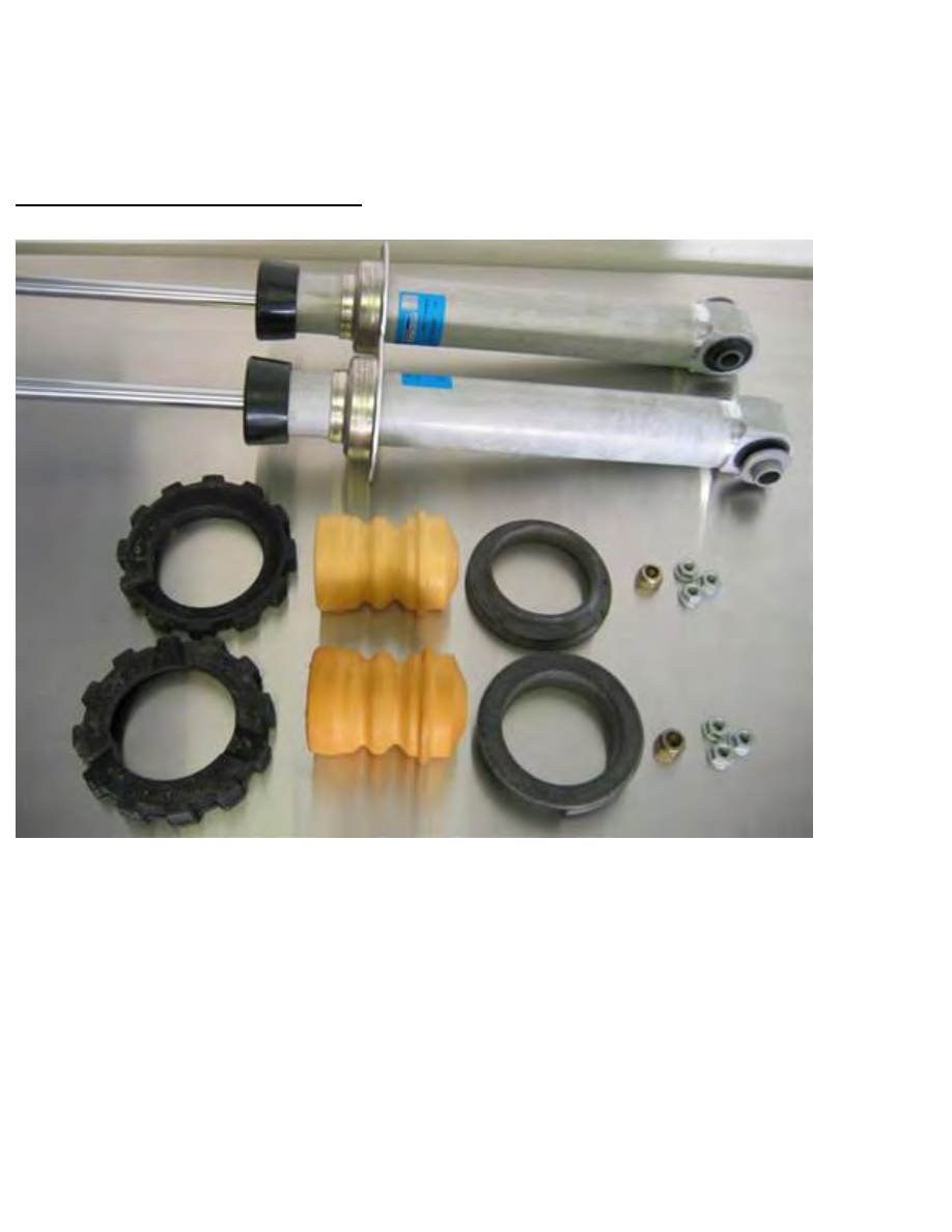
Parts, Tools, and Shop Supplies
2 x Sachs shock $82.75/each, 2 x upper spring pad (33-53-1-091-924) $3.04/each, 2 x bump stop (varies
by model/year/suspension) $11.92/each, 2 x lower spring pad (33-53-1-133-671) $5.28/each, 2 x self-
locking shock nut (33-52-1-137-360) $0.40/each, 6 x shock tower (collar) self-locking nut (31-33-1-092-
887) $0.40/each
Not shown (easy to break plastic clips and rivets): 4 x C-pillar panel plastic clips (51-43-8-189-311)
$0.45/each, 4 x rear shelf panel plastic rivets (51-11-1-964-186) $0.25/each, 7 x wheel well liner plastic
rivets (51-11-8-174-185) $0.17/each
Note: The Sachs new shock came with a shock self-locking nut, but was size 17mm not 16mm as
specified by BMW. This nut could be utilized successfully.
http://www.beisansystems.com/procedures/rear_shocks_procedure.htm (2 of 40)9/22/2009 10:45:58 AM
Beisan Systems - Procedures - Rear Shocks Procedure
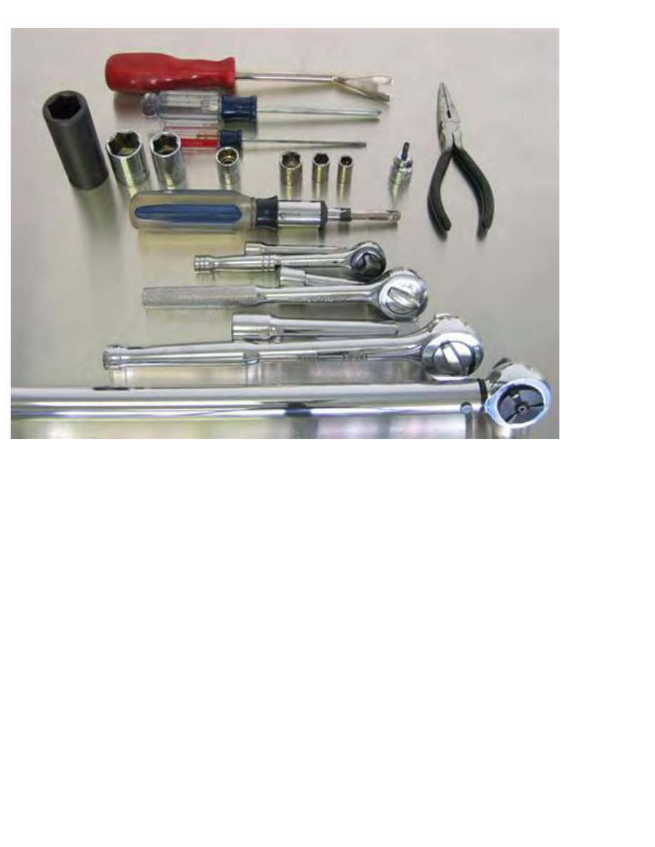
Needle nose pliers, panel remover (Lisle 35400, Door Upholstery Remover)
Middle size Philips screwdriver, small flathead screwdriver
4mm hex bit (Allen) socket 3/8”
8mm socket 1/4”, 10mm socket 1/4”, 13mm socket 1/4”, 13mm socket 3/8”, 16mm socket 1/2” (not
sown), 17mm socket 1/2”, 21mm socket 1/2”, 21mm deep socket 1/2”
1/4” driver, 1/4” ratchet w/ extension, 3/8” ratchet w/ extension, 1/2” ratchet w/ extension, 1/2” torque
wrench (27 Nm [20 ft-lb] - 127 Nm [94 ft-lb])
http://www.beisansystems.com/procedures/rear_shocks_procedure.htm (3 of 40)9/22/2009 10:45:58 AM
Beisan Systems - Procedures - Rear Shocks Procedure
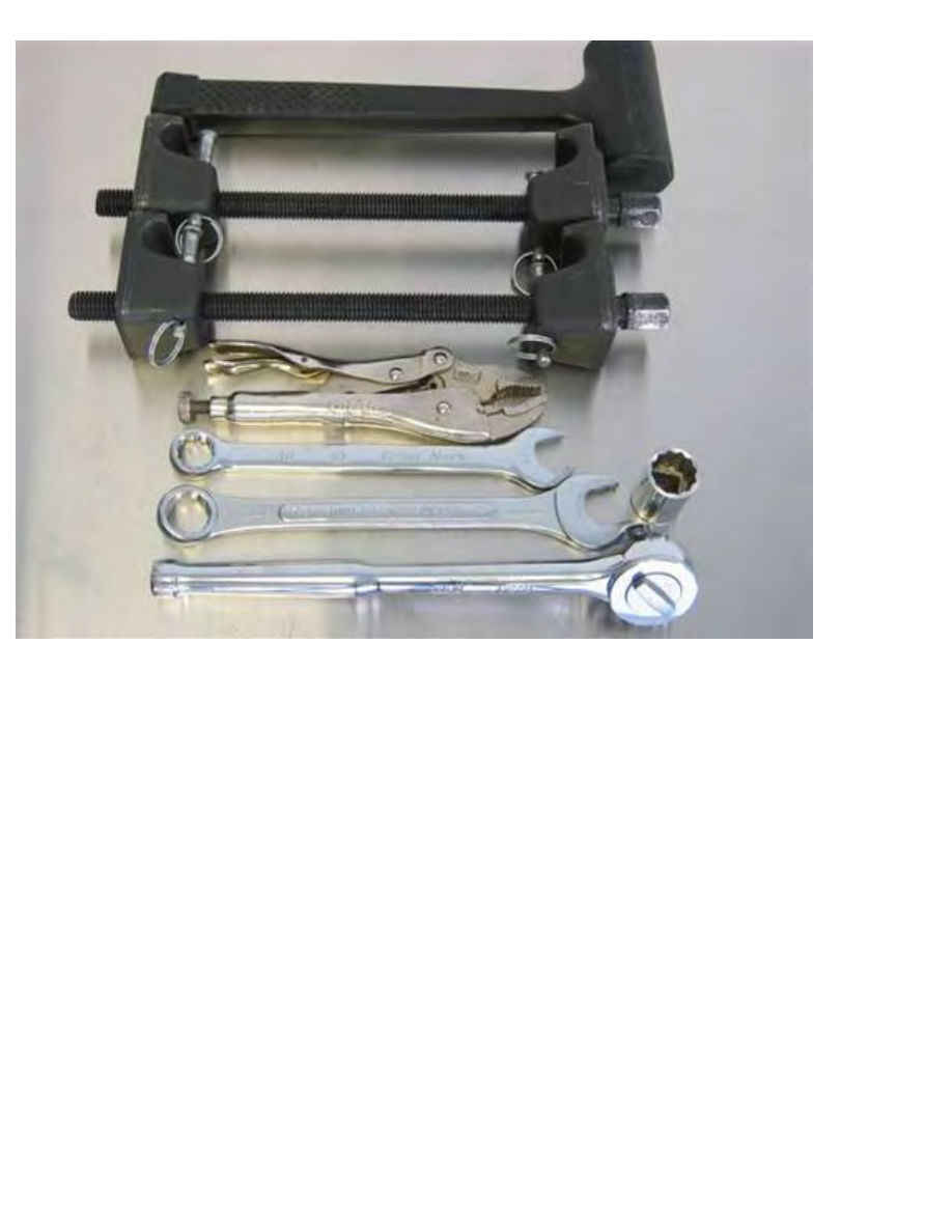
~1lb dead blow hammer
OEM strut spring compressor (#27036) AutoZone free w/ ~$40 deposit
Vise grip pliers
16mm combo wrench, 3/4” combo wrench
3/4” socket 1/2”, 1/2” ratchet
Note: 3/4” size is specific to indicated spring compressor
http://www.beisansystems.com/procedures/rear_shocks_procedure.htm (4 of 40)9/22/2009 10:45:58 AM
Beisan Systems - Procedures - Rear Shocks Procedure
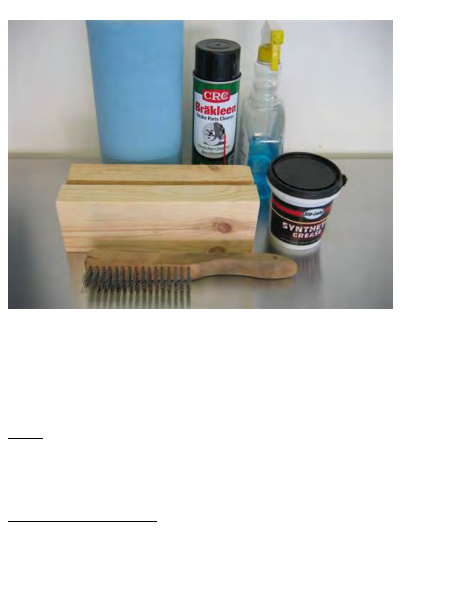
Paper towels, brake cleaner, glass cleaner
2 x 9 1/2” long (2x4) wood block, Graphite based grease (Sta-Lube, Synthetic Grease, CRC)
Stainless steel wire brush
Not shown: floor pad (old quilt)
Note: 9 1/2” wood block length is for 16” wheels and standard suspension. Other configurations will
likely need a length adjustment.
Repair
Fill up fuel tank. This is needed to achieve “empty weight position”, which is utilized in the final
tightening of the sock / wheel carrier mount at the end of the repair.
Note: Do not over fill tank as the filler hose will be manipulated during the repair procedure.
Removal of rear parcel shelf
Adjust front seats forward to facilitate more work space in rear.
http://www.beisansystems.com/procedures/rear_shocks_procedure.htm (5 of 40)9/22/2009 10:45:58 AM
Beisan Systems - Procedures - Rear Shocks Procedure
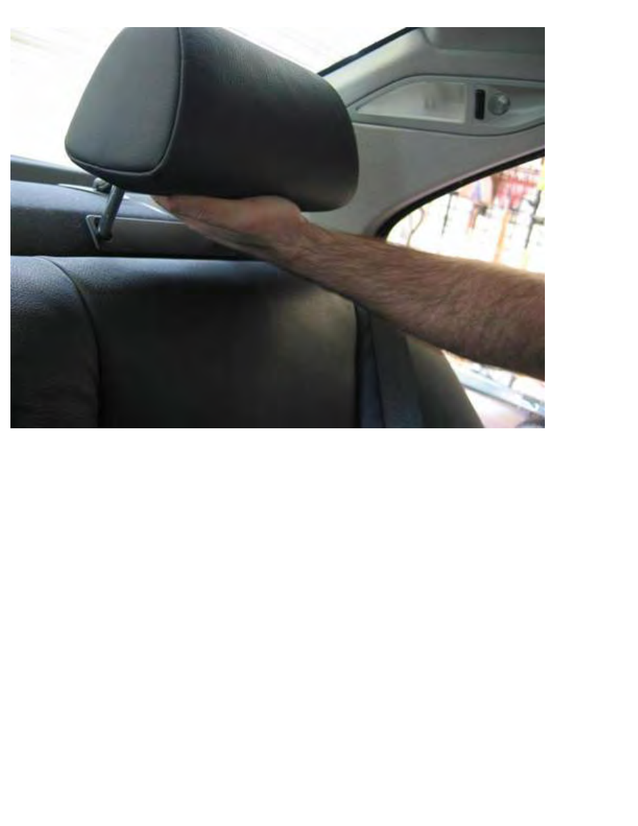
Remove rear seat head rests. Pull up on middle seat headrest and remove.
Adjust side seats’ headrest to highest position, then jar up headrest from bottom to remove (hand).
http://www.beisansystems.com/procedures/rear_shocks_procedure.htm (6 of 40)9/22/2009 10:45:58 AM
Beisan Systems - Procedures - Rear Shocks Procedure
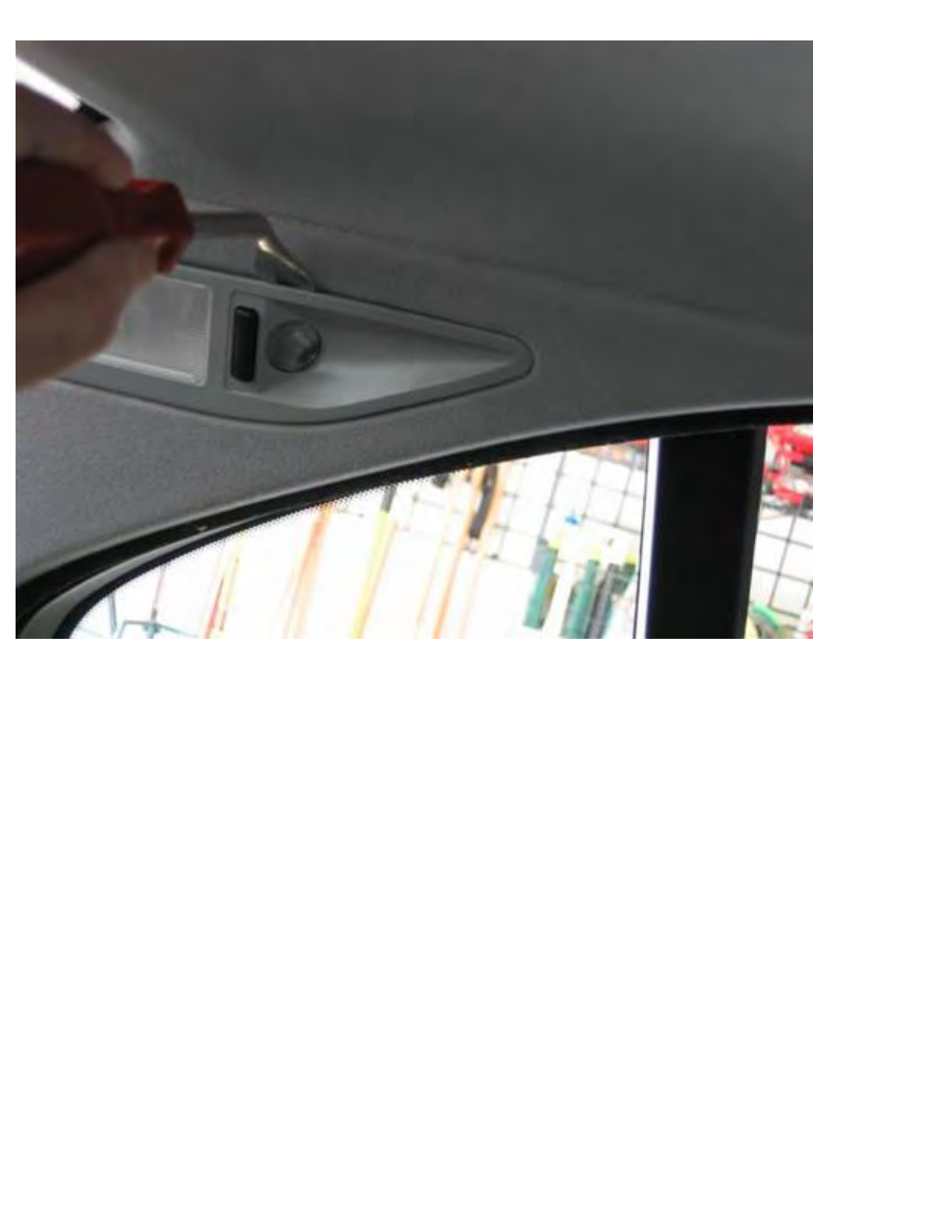
Remove rear C-pillar lights from trim. Pry from top (panel remover) and pull up/out.
http://www.beisansystems.com/procedures/rear_shocks_procedure.htm (7 of 40)9/22/2009 10:45:58 AM

Beisan Systems - Procedures - Rear Shocks Procedure
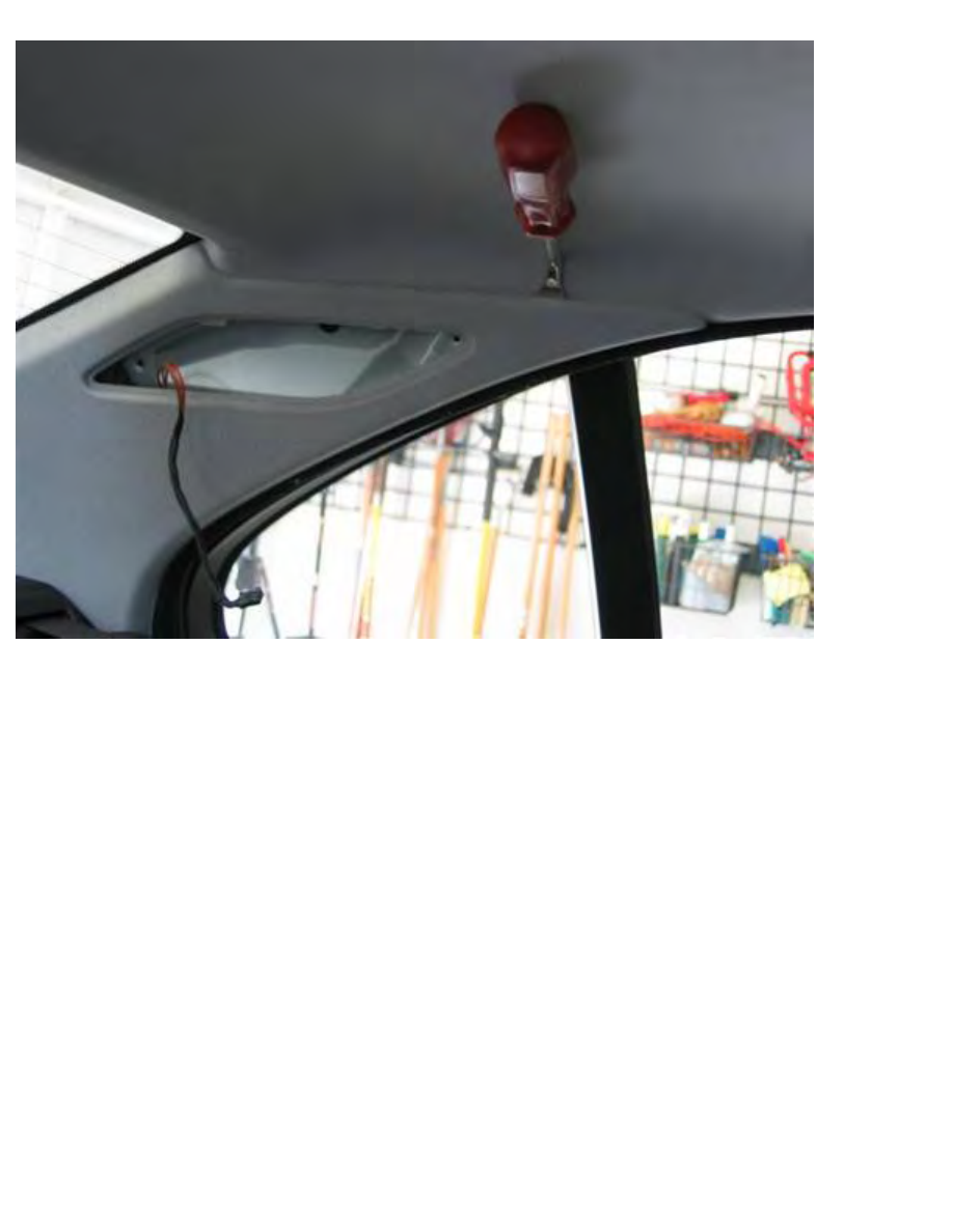
Remove electrical connector from C-pillar lights. Pull connector strait out, no clip (needle nose pliers).
http://www.beisansystems.com/procedures/rear_shocks_procedure.htm (8 of 40)9/22/2009 10:45:58 AM
Beisan Systems - Procedures - Rear Shocks Procedure
Remove C-pillar panels. Pry off panel top by leveraging between panel and mount clip (panel remover).
There are two clips, one at each side of top edge.
Pry front edge out from under door seal, and pull forward to remove panel.
http://www.beisansystems.com/procedures/rear_shocks_procedure.htm (9 of 40)9/22/2009 10:45:58 AM
Beisan Systems - Procedures - Rear Shocks Procedure
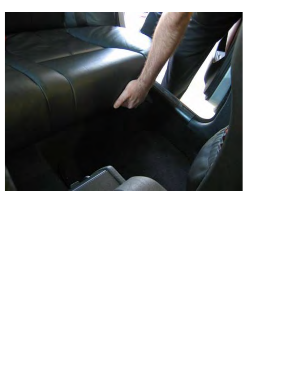
Pull up on rear seat at each side seat from front/bottom to dislodge seat from mount brackets (hand).
Pull seat bottom up and forward to remove. Let seat belt buckles slip down and out of seat access
cavities.
Clean up under seat bottom (glass cleaner / towels).
http://www.beisansystems.com/procedures/rear_shocks_procedure.htm (10 of 40)9/22/2009 10:45:58 AM
Beisan Systems - Procedures - Rear Shocks Procedure
Remove screws at each side bottom seat backrest (10mm socket 1/4” / 1/4” ratchet).
http://www.beisansystems.com/procedures/rear_shocks_procedure.htm (11 of 40)9/22/2009 10:45:58 AM
Beisan Systems - Procedures - Rear Shocks Procedure
Lift up on seat backrest at each side seat from bottom to dislodge seat from mount brackets (hand).
Pull left (driver side) shoulder harness to side of seat, and slide seat backrest out through left rear door.
http://www.beisansystems.com/procedures/rear_shocks_procedure.htm (12 of 40)9/22/2009 10:45:58 AM
Beisan Systems - Procedures - Rear Shocks Procedure
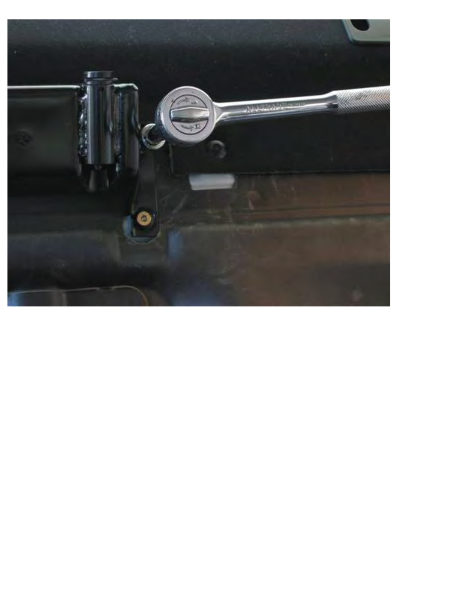
Unfasten bolts at bottom/base (hidden) of shoulder harnesses (17mm socket 1/2” / 1/2” ratchet &
extension).
Note: Middle belt strap plate mounts behind seat buckle plate.
http://www.beisansystems.com/procedures/rear_shocks_procedure.htm (13 of 40)9/22/2009 10:45:58 AM
Beisan Systems - Procedures - Rear Shocks Procedure
If present, remove 3 child seat anchors. Remove bolt plastic caps (panel remover). Unscrew bolts
(13mm socket 3/8” / 3/8” ratchet).
Note: Each bolt has washer, bracket, and washer/bushing, in sequential bolt insertion order.
http://www.beisansystems.com/procedures/rear_shocks_procedure.htm (14 of 40)9/22/2009 10:45:58 AM
Beisan Systems - Procedures - Rear Shocks Procedure
Remove middle seat headrest mounting bracket. Unscrew 4 bolts and remove (4mm hex bit 3/8” / 3/8”
ratchet & extension).
http://www.beisansystems.com/procedures/rear_shocks_procedure.htm (15 of 40)9/22/2009 10:45:58 AM
Beisan Systems - Procedures - Rear Shocks Procedure
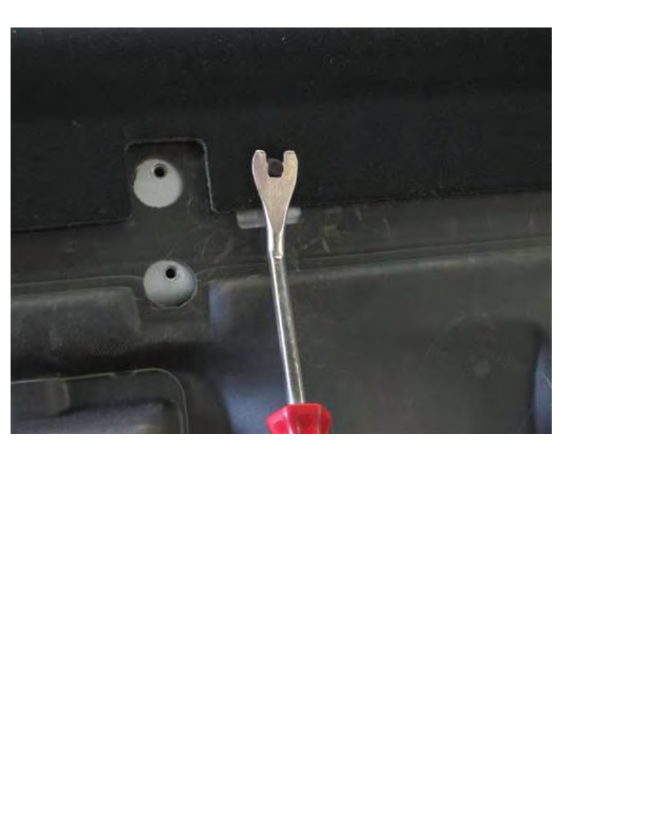
Pry off 4 shelf panel rivets. Pry off middle rivet pin (flathead, panel remover), then pry/twist between
car body and shelf panel to pull out rivet (panel remover).
http://www.beisansystems.com/procedures/rear_shocks_procedure.htm (16 of 40)9/22/2009 10:45:58 AM
Beisan Systems - Procedures - Rear Shocks Procedure
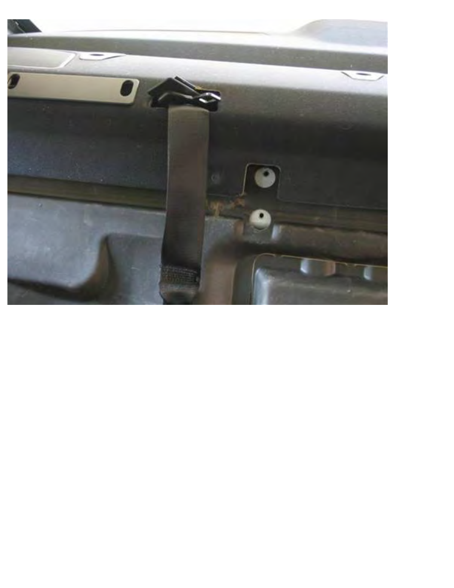
Pry off shoulder harness brackets from shelf. Pry bottom out (panel remover), then pull down and out.
Partially pull out shelf panel, and push brackets and shoulder harness apparatus through bracket opening.
http://www.beisansystems.com/procedures/rear_shocks_procedure.htm (17 of 40)9/22/2009 10:45:58 AM
Beisan Systems - Procedures - Rear Shocks Procedure
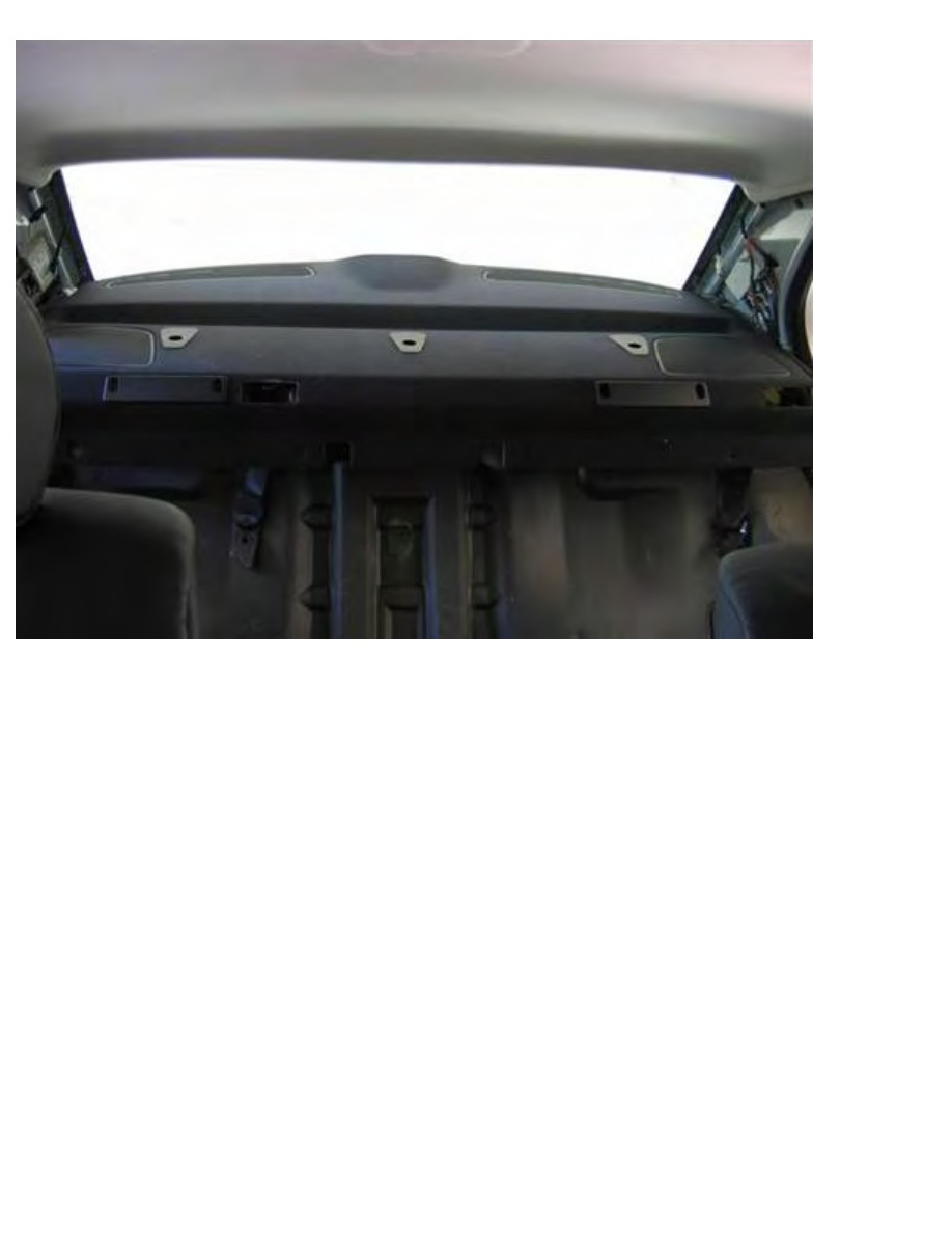
Pull out and remove rear shelf panel (hands).
http://www.beisansystems.com/procedures/rear_shocks_procedure.htm (18 of 40)9/22/2009 10:45:58 AM
Beisan Systems - Procedures - Rear Shocks Procedure
Remove speakers. Remove 2 mounting screws (Philips). Disconnect electrical connector. Pull out
speaker unit.
Remove insulation padding under speakers. Pull up and remove insulation surrounding seatbelt
controller. Peal back insulation to uncover shock tower.
Note: Remove seatbelt controller to ease insulation removal if necessary (16mm socket 1/2” / 1/2”
ratchet & extension).
http://www.beisansystems.com/procedures/rear_shocks_procedure.htm (19 of 40)9/22/2009 10:45:58 AM
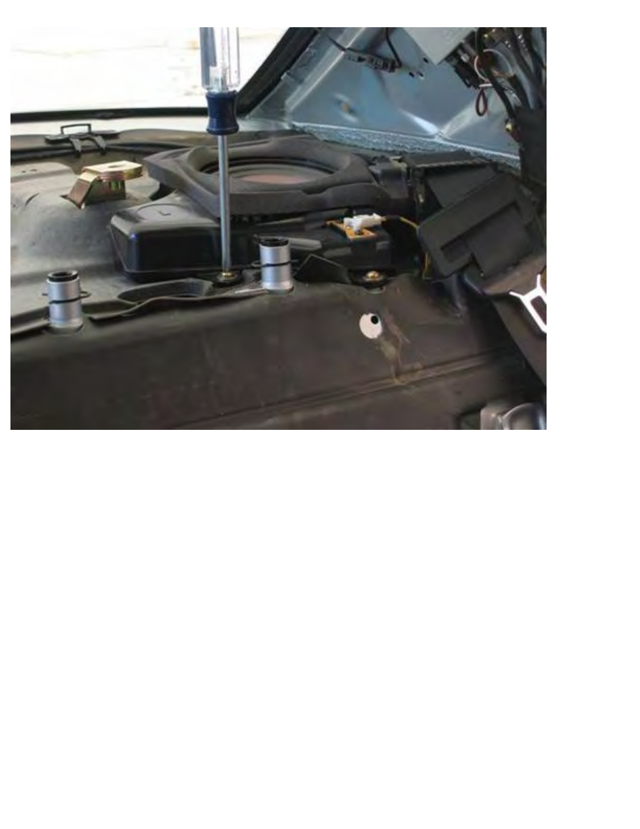
Beisan Systems - Procedures - Rear Shocks Procedure
Disconnect shock tower mounting. Remove center rubber cup. Remove 3 shock mount nuts (13mm
socket 1/4” / 1/4” ratchet & extension).
Removal of spring/shock from car
Raise rear of car and place on jack stands (follow appropriate procedure; chock both sides of both front
wheels). Remove rear wheels.
The following procedure shows the left side (driver side). The right side is the same but with minor
noted differences.
It’s more effective to perform the left side first since it’s illustrated with pictures.
http://www.beisansystems.com/procedures/rear_shocks_procedure.htm (20 of 40)9/22/2009 10:45:58 AM
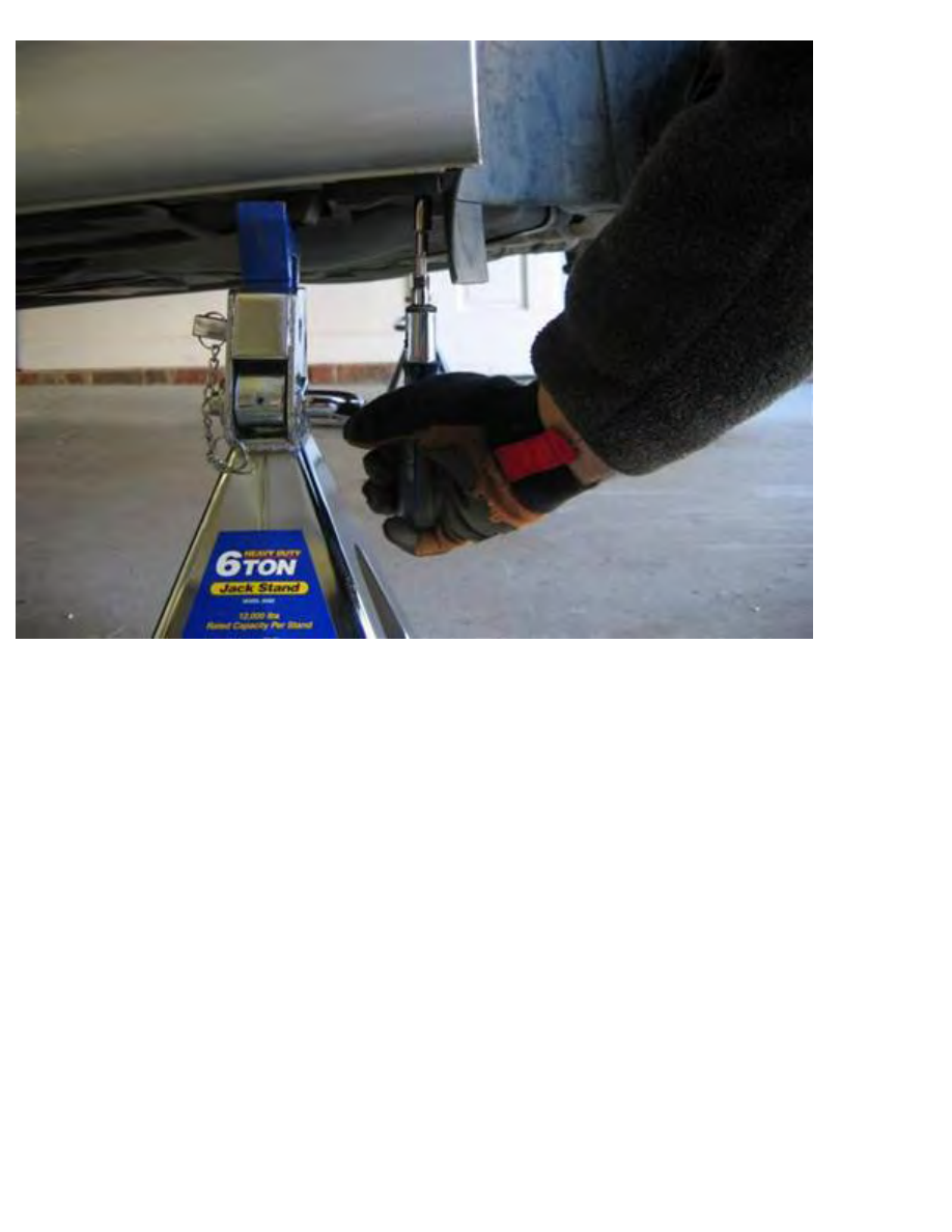
Beisan Systems - Procedures - Rear Shocks Procedure
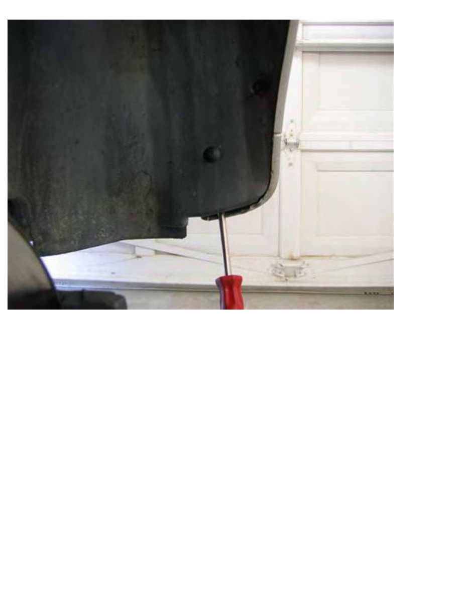
Remove 2 mud guard screws from under car (8mm 1/4” / 1/4” driver).
http://www.beisansystems.com/procedures/rear_shocks_procedure.htm (21 of 40)9/22/2009 10:45:58 AM
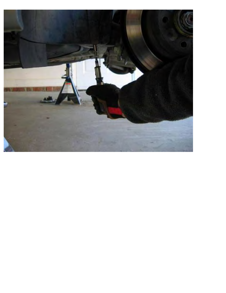
Beisan Systems - Procedures - Rear Shocks Procedure
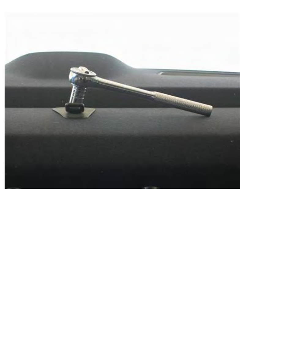
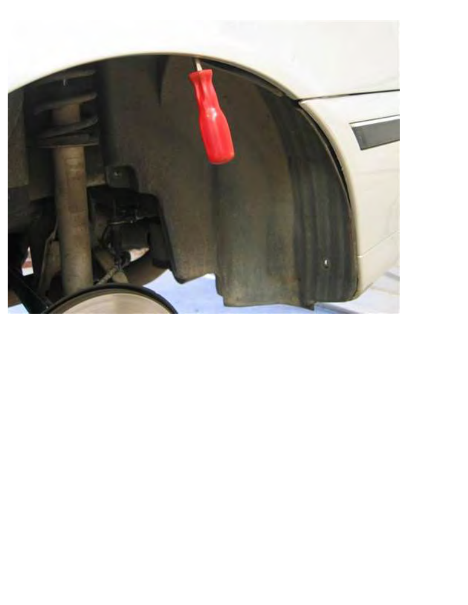
Remove wheel well liner screw under car adjacent to mud guard (8mm 1/4” / 1/4” driver).
http://www.beisansystems.com/procedures/rear_shocks_procedure.htm (22 of 40)9/22/2009 10:45:58 AM
Beisan Systems - Procedures - Rear Shocks Procedure
Remove 2 wheel well liner mount nuts at each side of shock (10mm 1/4” / 1/4” driver).
http://www.beisansystems.com/procedures/rear_shocks_procedure.htm (23 of 40)9/22/2009 10:45:58 AM
Beisan Systems - Procedures - Rear Shocks Procedure
Pry off 3 wheel well plastic rivets at rear. Pry out middle rivet pin (flathead, panel remover), then pry/
twist between bumper and liner to pull out rivet (panel remover).
Note: Third, none visible rivet, is at inside rear of fender/bumper.
Left side: Remove plastic rivet at rear frame mount under car (flathead, panel remover).
http://www.beisansystems.com/procedures/rear_shocks_procedure.htm (24 of 40)9/22/2009 10:45:58 AM
Beisan Systems - Procedures - Rear Shocks Procedure
Remove wheel well liner. Pry off liner at fender rim (panel remover).
Pull liner down and out of car.
Note: Liner may also be removed from inner mount bolts and pushed up to facilitate easier removal at
the fender rim.
http://www.beisansystems.com/procedures/rear_shocks_procedure.htm (25 of 40)9/22/2009 10:45:58 AM
Beisan Systems - Procedures - Rear Shocks Procedure
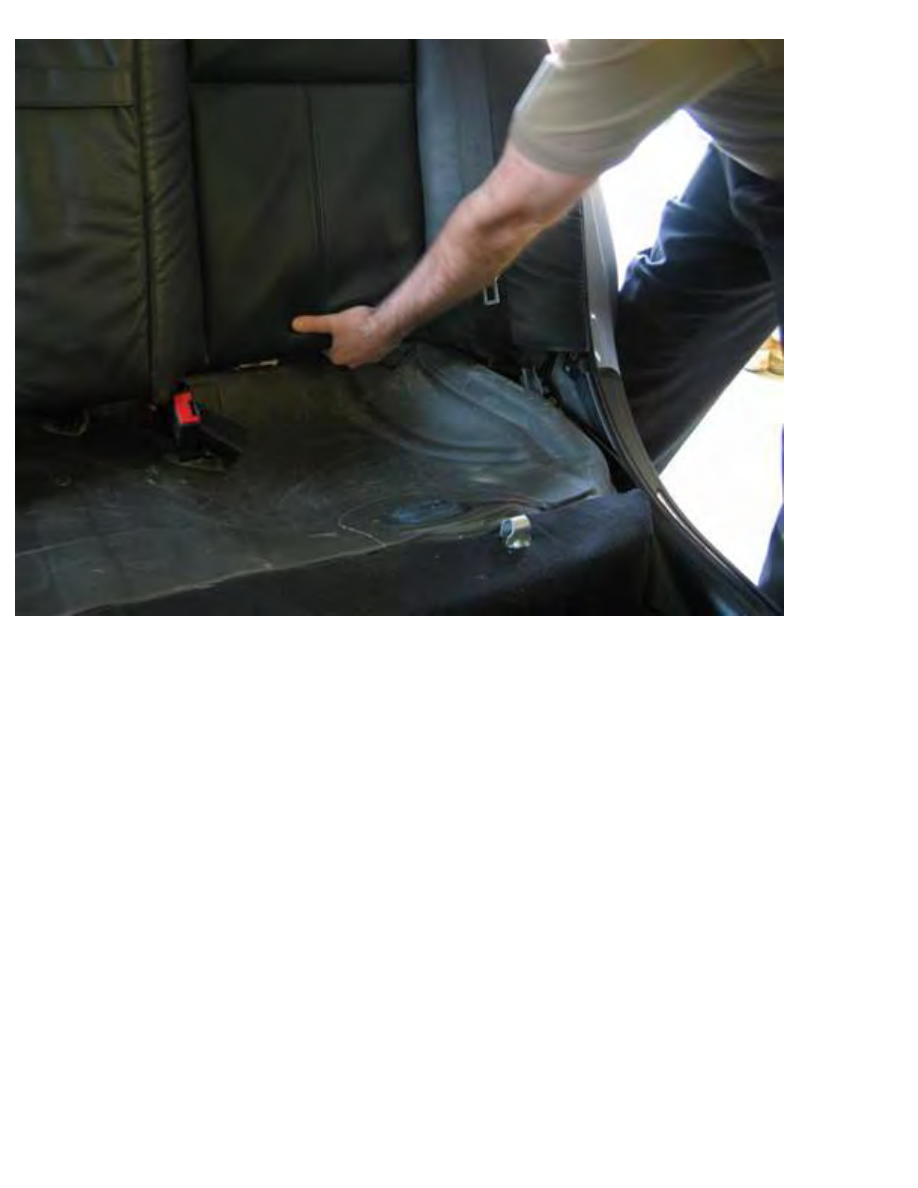
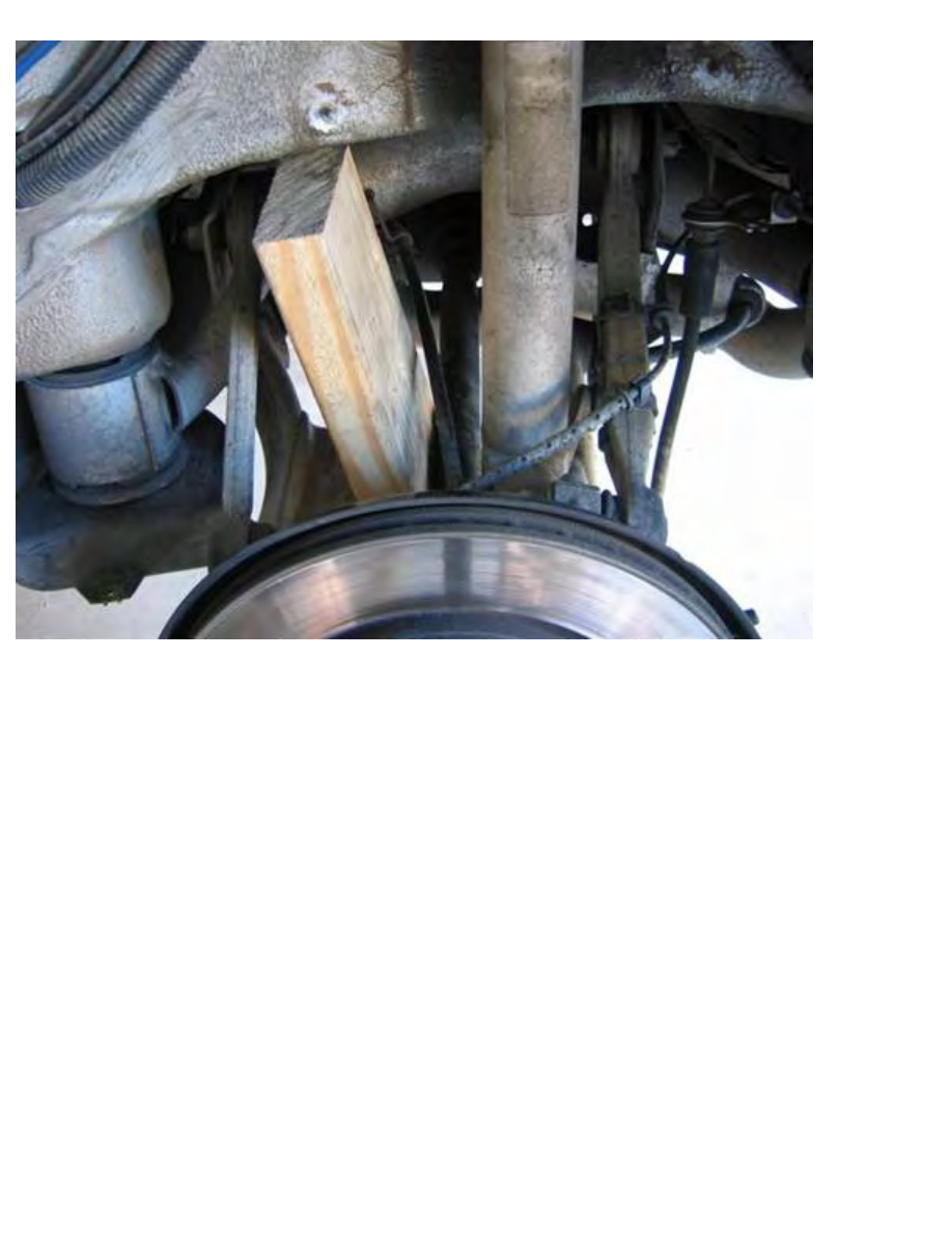
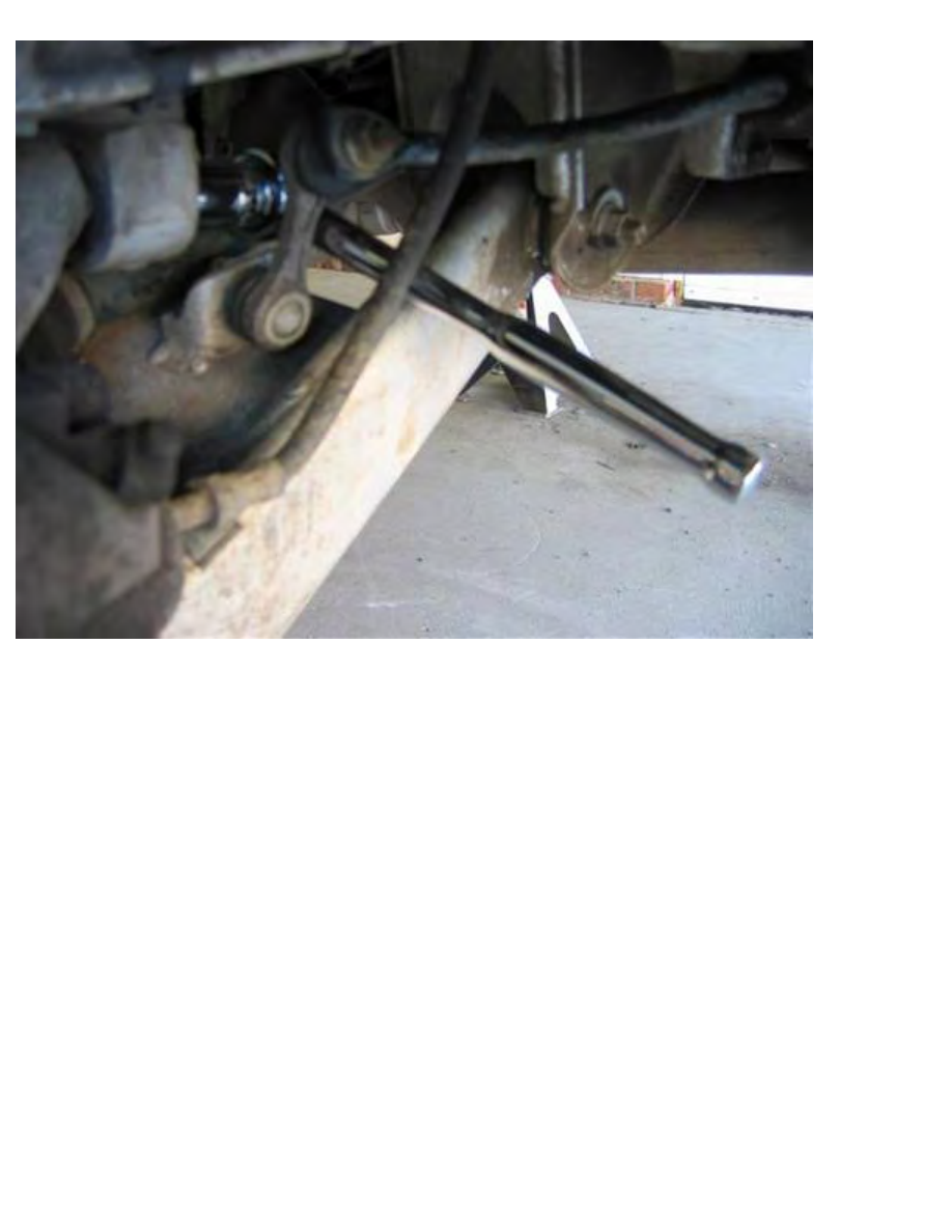
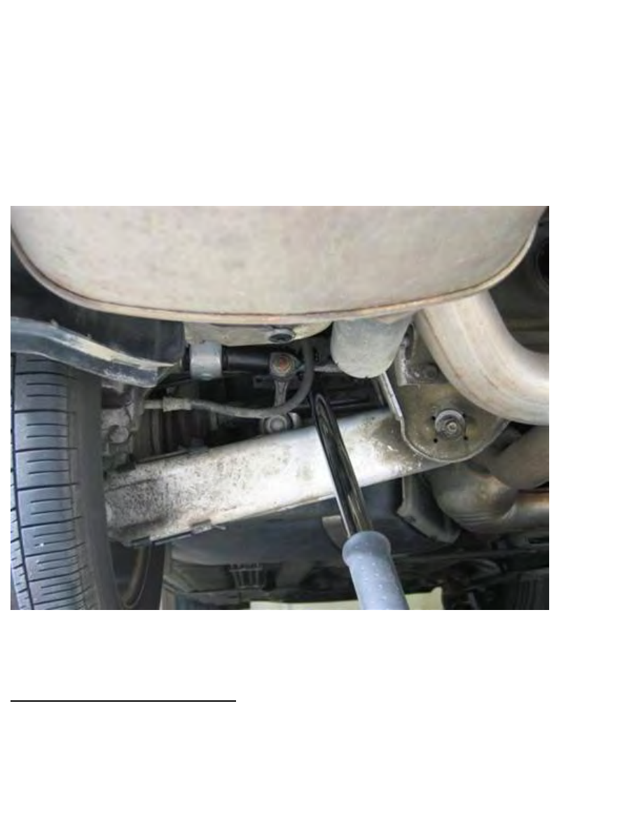
Place vertical separator between swing arm and car body. While pressing down on wheel hub (foot/leg),
wedge in separator at swing arm front of axel (wood block).
Note: This step will serve to restrain wheel carrier / swing arm movement, and facilitate space for shock
manipulation.
Note: Be careful not to scrape against underbody coating. Shorten wedge length as necessary to facilitate
insertion without scrapping.
http://www.beisansystems.com/procedures/rear_shocks_procedure.htm (26 of 40)9/22/2009 10:45:58 AM
Beisan Systems - Procedures - Rear Shocks Procedure
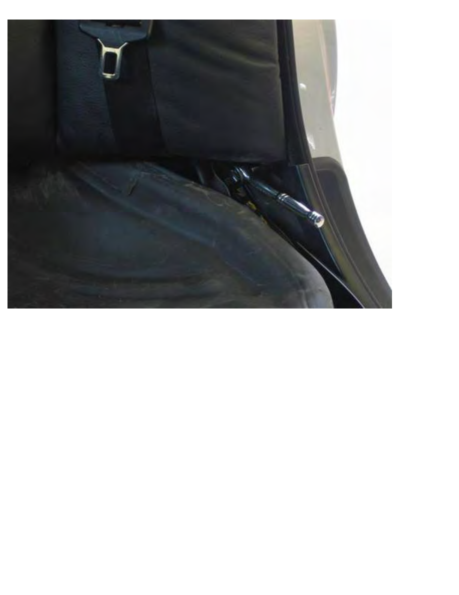
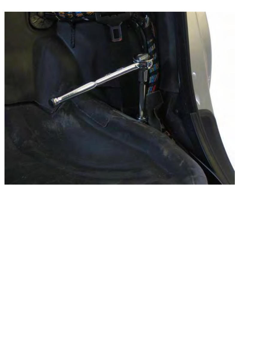
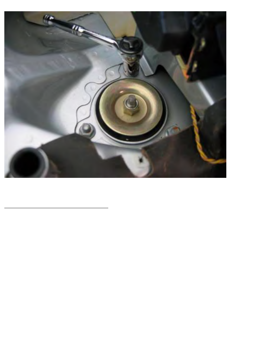
Remove shock / wheel carrier mounting bolt (21mm socket 1/2” / 1/2” ratchet).
http://www.beisansystems.com/procedures/rear_shocks_procedure.htm (27 of 40)9/22/2009 10:45:58 AM
Beisan Systems - Procedures - Rear Shocks Procedure
Left side:
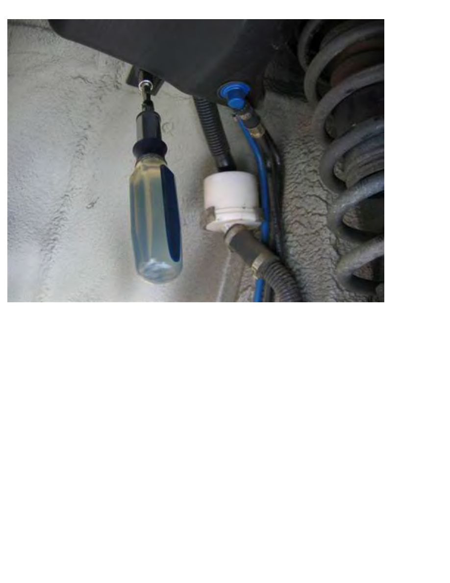
Remove fuel evaporation tank at upper wheel well. Remove mounting nut at front end (10mm socket
1/4” / 1/4” driver). Unclip hoses/cables from mounting bracket. Pull tank forward and down. Rotate tank
and hoses/cables down and to rear.
http://www.beisansystems.com/procedures/rear_shocks_procedure.htm (28 of 40)9/22/2009 10:45:58 AM
Beisan Systems - Procedures - Rear Shocks Procedure
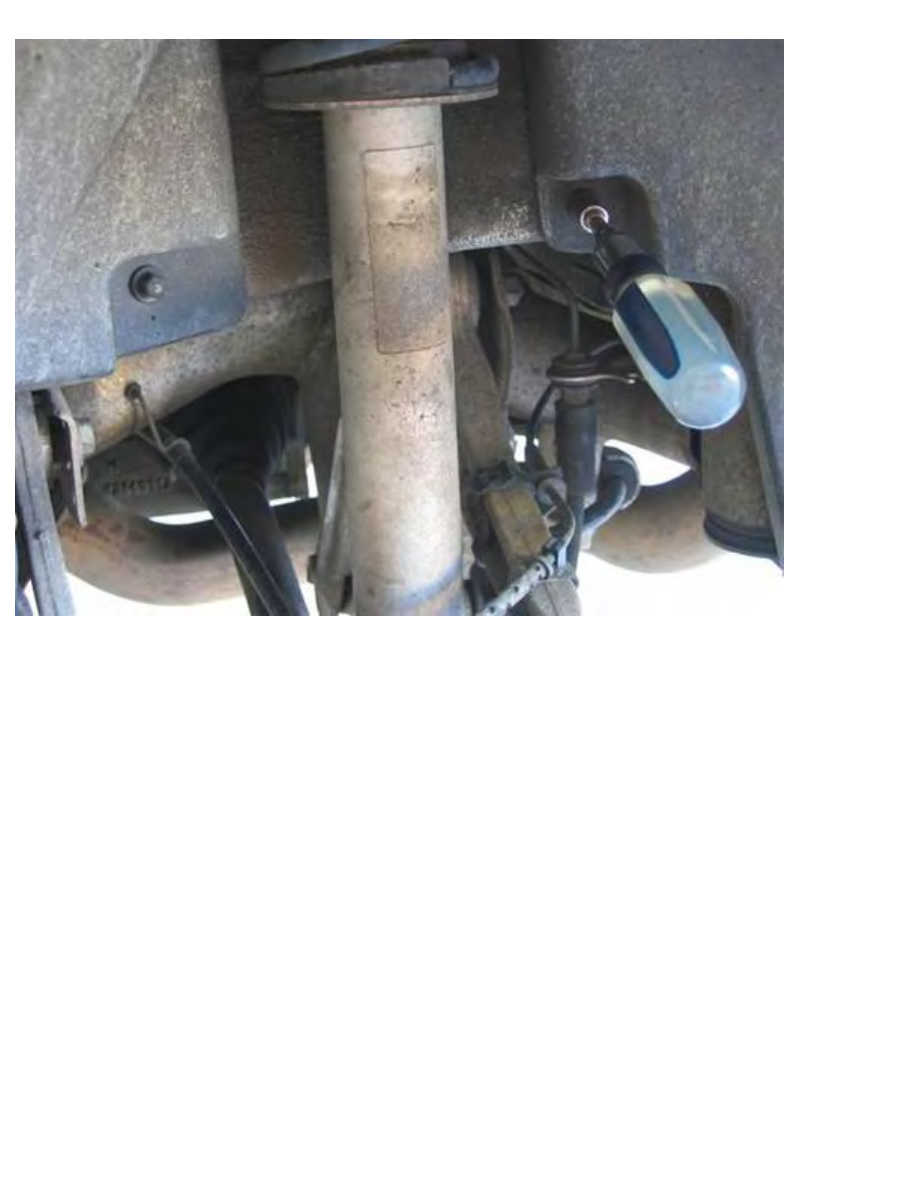
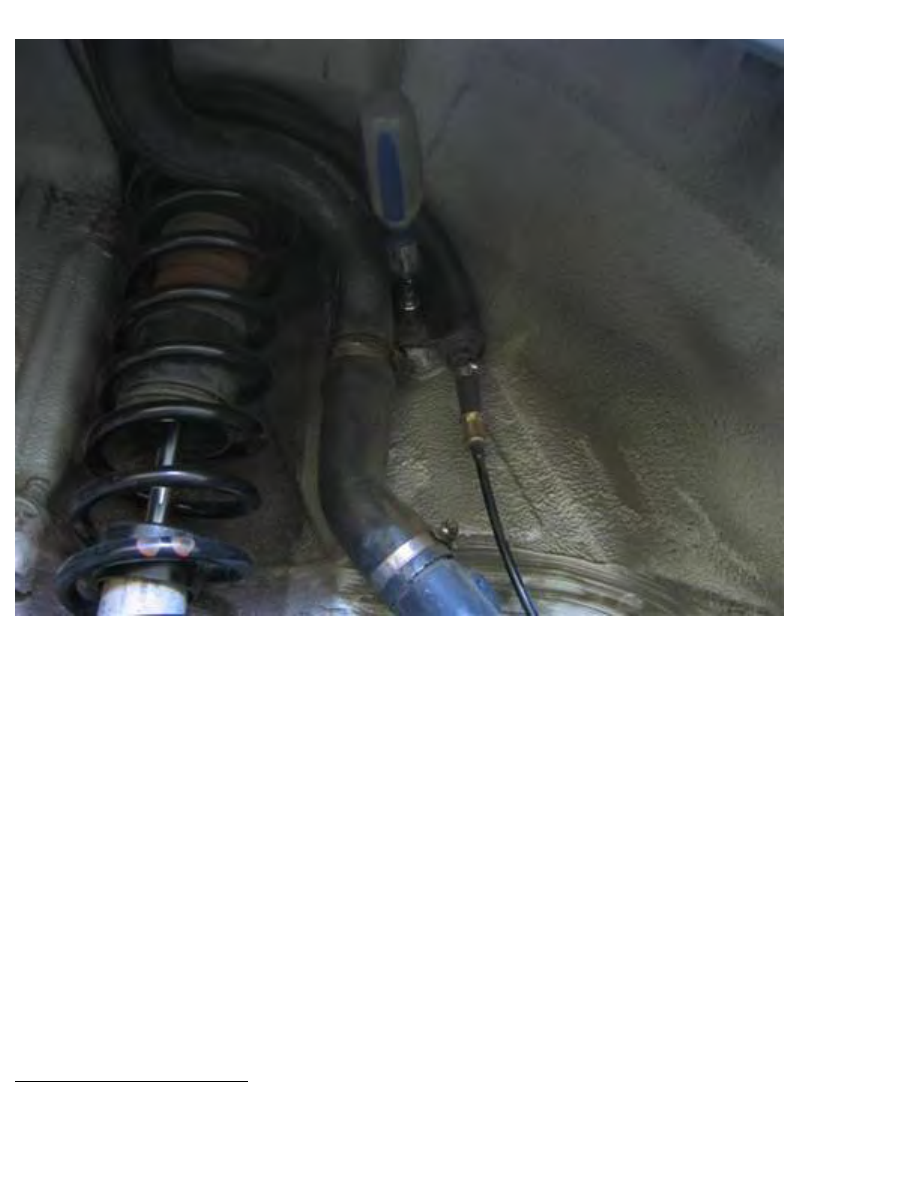
Right side:
Remove fuel hoses from wheel well mounting.
Remove fuel filler cap and block off inner opening (crumpled paper towel).
Remove nut at midway bracket (picture) (10 mm socket 1/4” / 1/4” driver).
Remove nut at hose top bracket (10 mm socket 1/4” / 1/4” driver).
Pull filler neck into wheel well and pull off top bracket.
Pull off midway bracket.
Fold hose down and rest hose neck on rotor.
Remove shock assembly from wheel well.
Left side: Rotate shock 180° so shock protruding bushing points to car inboard side. Move shock bottom
to car inboard side, while moving shock top down and to car outboard side. Remove shock from wheel
well.
Repeat procedure for second side.
Replacement of shock
http://www.beisansystems.com/procedures/rear_shocks_procedure.htm (29 of 40)9/22/2009 10:45:58 AM
Beisan Systems - Procedures - Rear Shocks Procedure
Clean spring thoroughly (glass cleaner / towels). There should be no debris or grease on spring when
done; clean and dry.
Coat both spring press spindle (bolt) threads with lubricant (graphite based grease). Also coat both
spindle heads clasp contact surfaces.
Note: This is essential for proper function and maintenance of tool.
Clean spring press clasps (coil seats) (brake cleaner / towels).
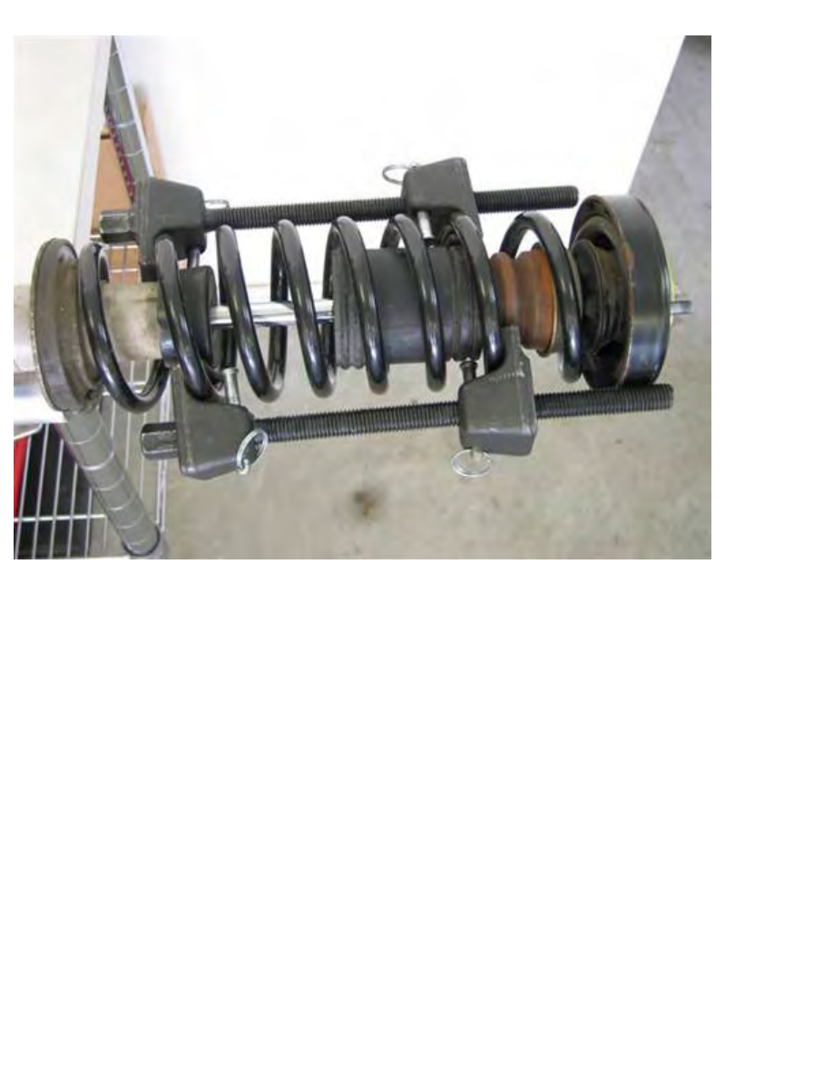
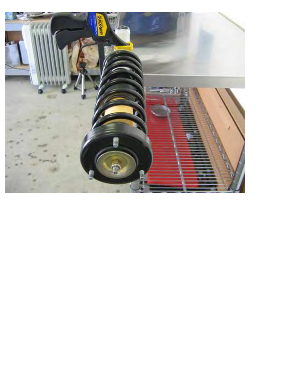
Stand shock vertically on end.
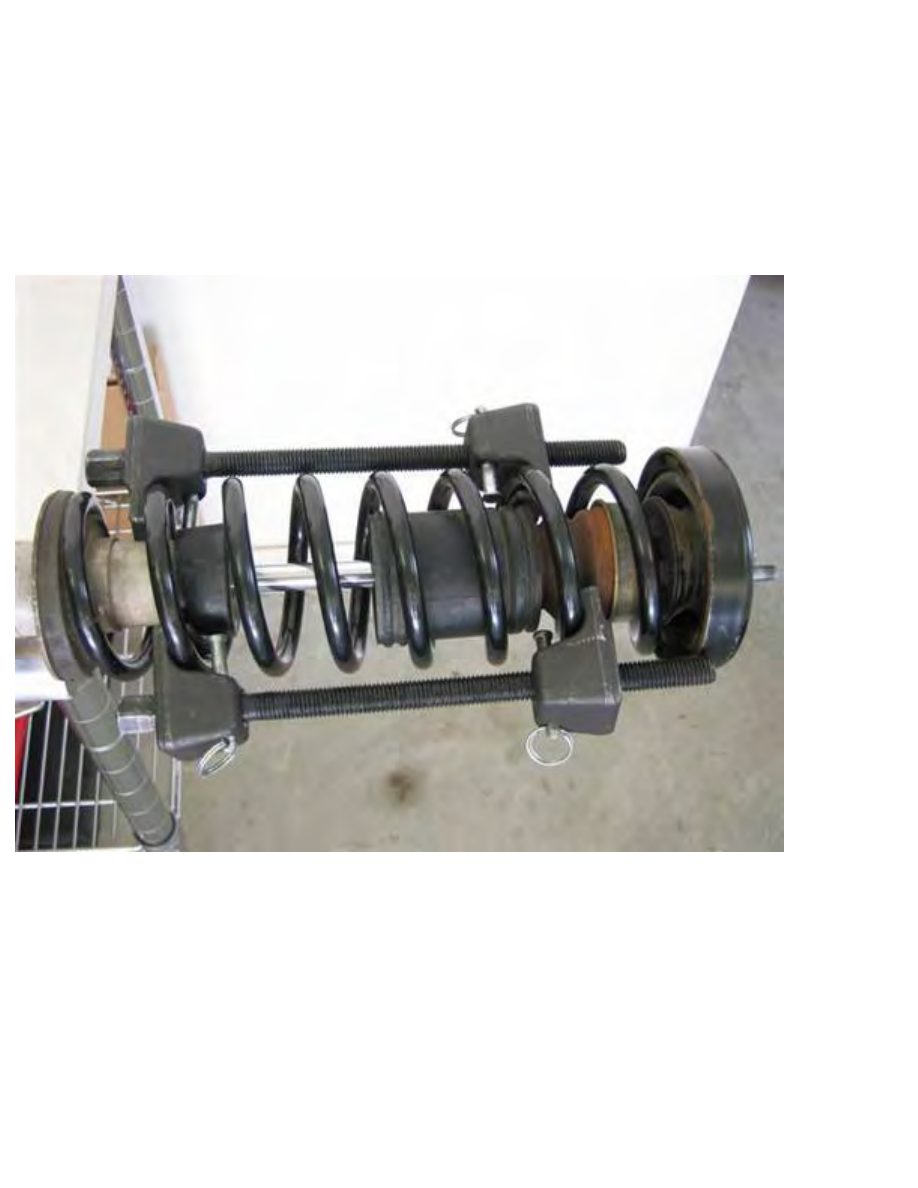
Place spring press tail clasp on coil at bump stop top. Work clasp as far up spring/coil without jamming
against a component.
Place spring press head clasp on coil, 5 coils down spring, keeping spindle strait on shock axis.
Tighten spindle to maintain clasps positions.
Perform same as above with second spring press, but placing first spring press tail clasp 180° down coil
from first spring press tail clasp.
Spring presses should be on opposite sides of spring.
http://www.beisansystems.com/procedures/rear_shocks_procedure.htm (30 of 40)9/22/2009 10:45:58 AM
Beisan Systems - Procedures - Rear Shocks Procedure
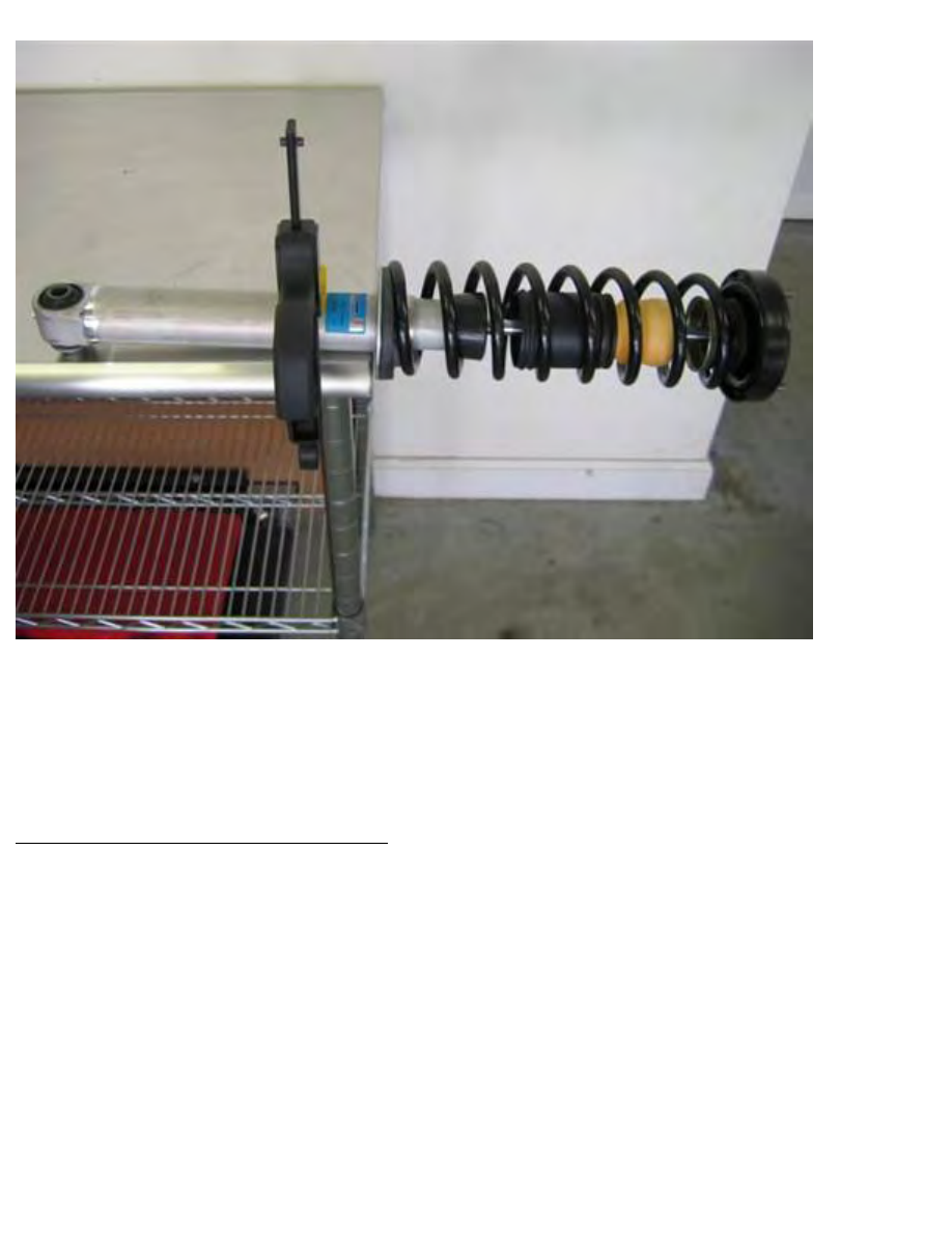
Note: It’s best to have shock horizontal when performing press process (floor pad or lap).
Tighten spindles (3/4” socket 1/2” / 1/2” ratchet | 3/4” combo wrench), rotating often between spindles.
Maintaining proportional spindle clasp to clasp lengths is essential to keeping a spring press from
sliding. Be careful not to jar spring presses.
Press process is complete when spring has some play between upper and lower seats, ~2” pressed.
http://www.beisansystems.com/procedures/rear_shocks_procedure.htm (31 of 40)9/22/2009 10:45:58 AM
Beisan Systems - Procedures - Rear Shocks Procedure
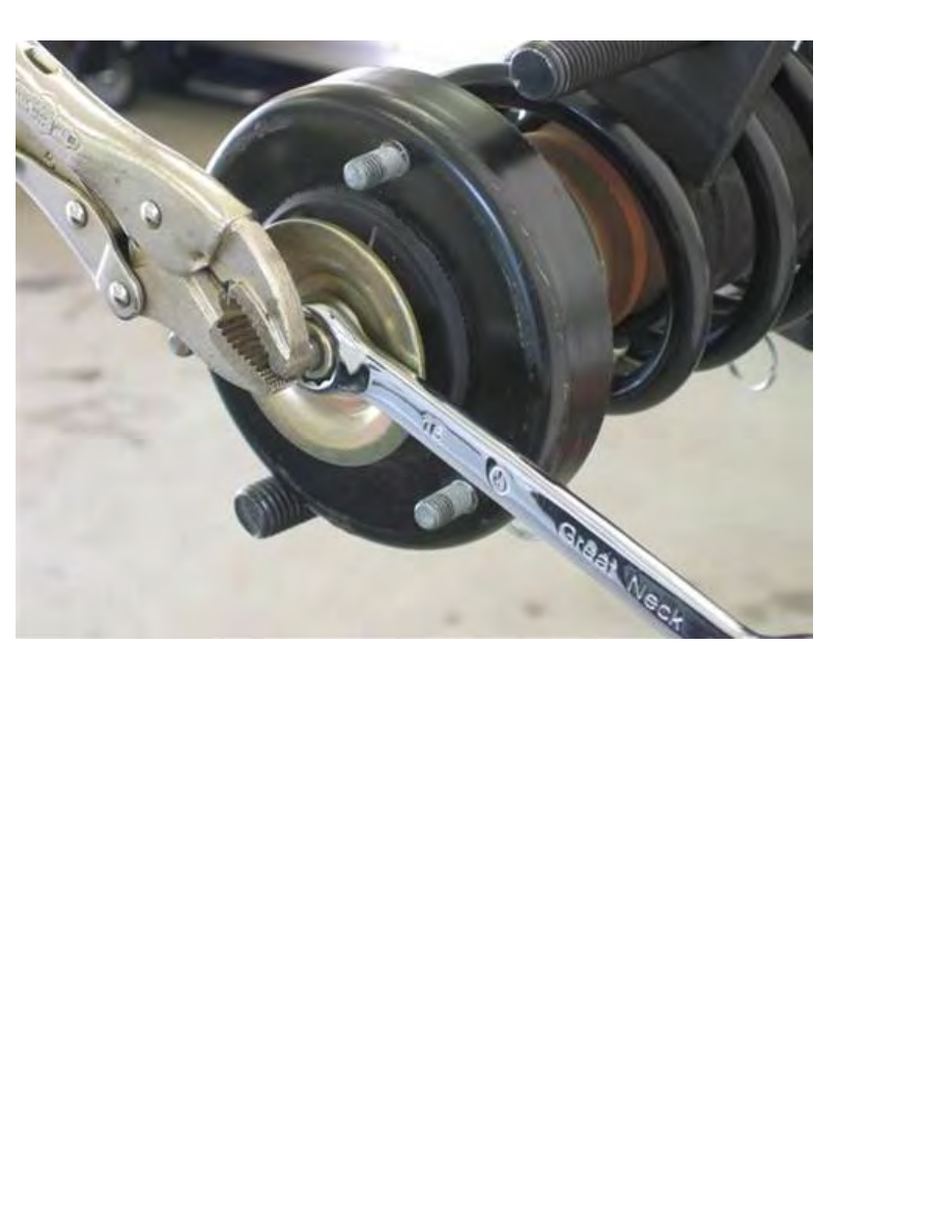
Note: I performed the following with shock standing on end.
Counter torque shock mount nut and shock piston rod to break nut seize (16mm combo wrench, vice
grips).
Counter hold shock piston rod and unscrew shock mount nut to remove nut (vice grips, 16mm combo
wrench).
Dismantle shock assy.
Remove bump stop / plastic boot from spring through spring lower end. Push through on bump stop
(dead blow hammer handle), and collapse plastic boot rim as needed.
Clean reusable parts (brake cleaner (metal) | glass cleaner (rubber/plastic) / towels, wire brush); large
washer, shock mount, metal cup, plastic boot, end coils of spring.
http://www.beisansystems.com/procedures/rear_shocks_procedure.htm (32 of 40)9/22/2009 10:45:58 AM
Beisan Systems - Procedures - Rear Shocks Procedure
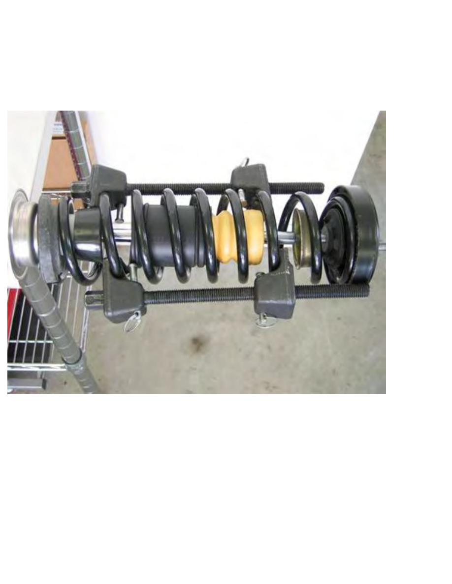
Note: Above picture shows exact positioning discussed below.
Insert/twist new bump stop tapered end into plastic boot accordion indentation end, until bump stop
mates with accordion indentation.
Insert bump stop / plastic boot into spring from spring upper end. Push in on bump stop (dead blow
hammer handle), and collapse plastic boot rim as needed
Place new lower spring pad on new shock lower spring seat (perch).
Place new upper spring pad on upper spring seat (shock mount bottom end). Orient pad so 3 inside
indentations align to 3 bolt heads.
With new shock standing on end (floor pad), assemble shock apparatus.
Place spring with boot/stop onto piston rod. Push bump stop down onto piston rod.
Place metal cup, concave side down, onto piston rod.
Place shock mount on piston rod, placing spring tip into upper spring pad notch.
http://www.beisansystems.com/procedures/rear_shocks_procedure.htm (33 of 40)9/22/2009 10:45:58 AM
Beisan Systems - Procedures - Rear Shocks Procedure
Place large washer, concave side up, on piston rod.
Place new self-locking shock mount nut onto piston rod and initially screw on (hand).
Counter hold shock piston rod and tighten shock mount nut (vice grips, 16mm combo wrench).
Fully tighten, 27 Nm (20 ft-lb) (vice grips, 16mm combo wrench).
Note: It’s best to have shock horizontal when uncompressing spring (floor pad or lap).
Push spring up shock piston rod, pressing spring tip into upper spring pad notch.
Place lower spring pad onto spring bottom, aligning pad notch onto spring tip.
Unscrew spring presses, rotating often between spindles (3/4” socket / 1/2” ratchet | 3/4” combo
wrench). Maintaining proportional spindle clasp to clasp lengths is essential to keeping a spring press
from sliding. Be careful not to jar spring presses.
http://www.beisansystems.com/procedures/rear_shocks_procedure.htm (34 of 40)9/22/2009 10:45:58 AM
Beisan Systems - Procedures - Rear Shocks Procedure
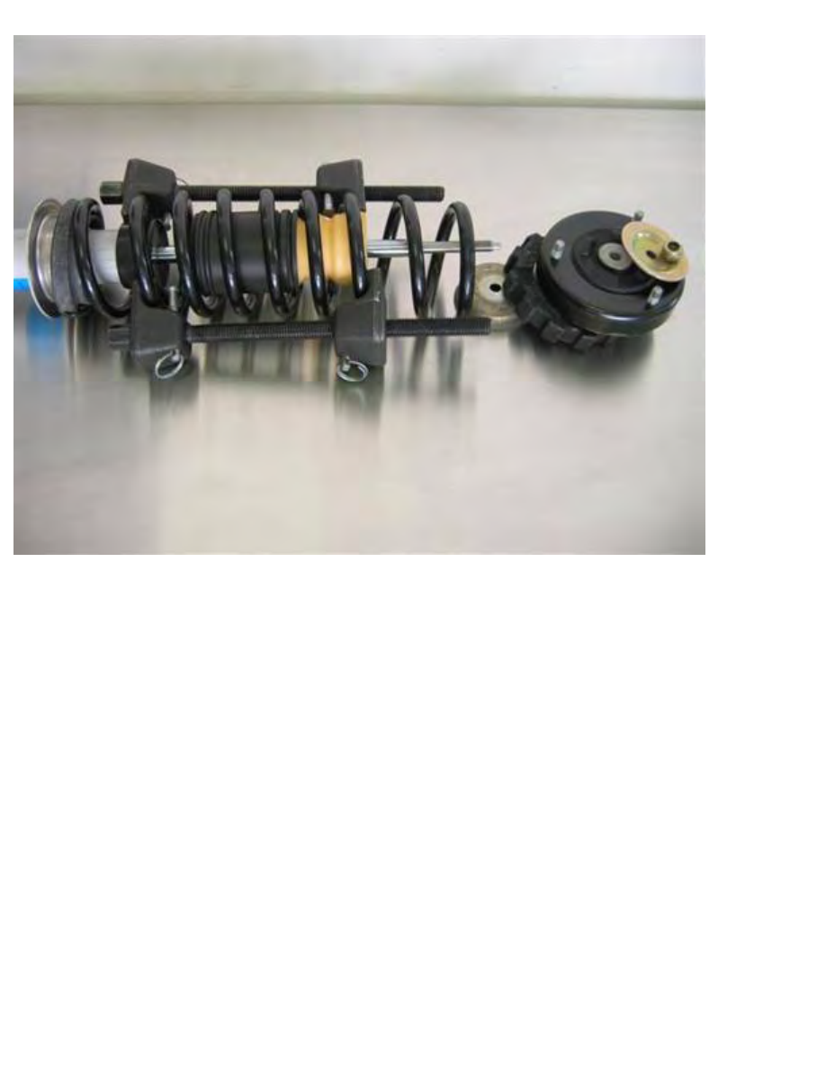
Note: Picture shows shock after uncompressing is complete.
Once lower spring pad and spring bottom moderately seat onto shock lower seat (perch), align shock
short bushing end middle with one of three bolts at shock mount top.
Rotate shock counter to spring coil downward spiral to maintain lower spring pad notch on spring end.
Stop when perfectly aligned. If alignment position is overshot, continue turning shock and align with
next bolt.
http://www.beisansystems.com/procedures/rear_shocks_procedure.htm (35 of 40)9/22/2009 10:45:58 AM
Beisan Systems - Procedures - Rear Shocks Procedure
Continue uncompressing spring, rotating often between spring presses and not jarring them.
Once spring has fully seated and spring presses are loose, remove spring presses.
Adjust position of spring bottom coil onto spring pad (dead blow hammer).
Repeat procedure for second side.
Installation of spring/shock on car
Clean (brake cleaner (metal) | glass cleaner (rubber/plastic) / towels, wire brush) following parts:
1. Wheel carrier shock mount surface and mounting bolt
2. Shock tower bolt/nut contact surfaces.
3. Wheel well liner top side, and bottom side mount contact surfaces.
4. Wheel well inner rim and liner mounting bolts.
Insert shock assy into wheel well (reverse of removal).
Align shock bottom protruding bushing with wheel carrier shock mount.
Insert shock mount 3 bolts into shock tower holes.
Insert shock bushing into wheel carrier shock mount.
http://www.beisansystems.com/procedures/rear_shocks_procedure.htm (36 of 40)9/22/2009 10:45:58 AM

Beisan Systems - Procedures - Rear Shocks Procedure
Initially screw on 3 new self-locking nuts onto shock mount at rear shelf.
Screw on shock / wheel carrier mounting bolt (hand).
Tighten bolt until snug, then loosen 1/2 turn (21mm socket 1/2” / 1/2” ratchet).
Note: Bolt should only be tightened fully with car resting on ground (later step).
Remove vertical separator between swing arm and car body. While pressing down on wheel hub (foot/
leg), remove separator (wood block).
Left side:
Remount fuel evaporation tank at upper wheel well. Insert tank rear tabs into mounting slots. Insert front
mounting hole onto wheel well mounting bolt. Screw on and tighten mounting nut (10mm socket 1/4” /
1/4” driver). Clip hoses/cables onto mounting bracket.
Right side:
Insert fuel filler neck into fuel compartment.
Insert upper hose mounting bracket onto upper mounting bolt.
Insert middle hose mounting bracket onto middle mounting bolt.
Screw on and tighten mounting nuts onto mounting bolts.
Reinstall fuel filler cap.
Reinstall wheel well liner.
Insert liner into wheel well and mount onto 2 bolts at each side of shock. Verify liner upper rim fits to
outside of shock mount.
Pry liner outer rim into fender rim, working from rear to front (hands).
Screw on and tighten 2 mud guard screws (8mm 1/4” / 1/4” driver).
Screw on and tighten liner screw adjacent to mud guard (8mm 1/4” / 1/4” driver).
Insert 3 wheel well plastic rivets at rear. Insert rivet with middle pin withdrawn, then insert pin.
Left side: Install plastic rivet at rear frame mount under car.
Screw on and tighten 2 wheel well liner mounting nuts at each side of shock (10mm 1/4” / 1/4” driver).
Fully tighten 3 shock mount nuts (rear shelf), 28 Nm (21 ft-lb) (13mm socket 1/4” / 1/4” ratchet &
extension).
http://www.beisansystems.com/procedures/rear_shocks_procedure.htm (37 of 40)9/22/2009 10:45:58 AM
Beisan Systems - Procedures - Rear Shocks Procedure
Reinstall (twist on) shock mount rubber cup, and orient tabs to fit into body notches.
Repeat procedure for second side.
Install rear wheels and lower car rear (follow appropriate procedure).
Move car ~20ft to allow rear suspension to settle.
With car on ground (“empty weight position”), tighten both sides’ shock / wheel carrier mount bolt
(21mm deep socket 1/2” / 1/2” ratchet).
Fully tighten, 127 Nm (94 ft-lb) (21mm deep socket 1/2” / 1/2” torque wrench).
Installation of rear parcel shelf
Reinstall insulation padding over shock towers. Remount insulation around seat belt controllers.
Note: Reinstall seatbelt controller(s) if previously removed (16mm socket 1/2” / 1/2” ratchet &
extension).
http://www.beisansystems.com/procedures/rear_shocks_procedure.htm (38 of 40)9/22/2009 10:45:58 AM

Beisan Systems - Procedures - Rear Shocks Procedure
Reinstall speakers. Insert rear tab into mounting slot. Screw on and tighten 2 mounting screws (Philips).
Reconnect electrical connector.
Reinsert rear shelf panel.
Pull shoulder harness apparatuses through shelf bracket openings.
Remount shoulder harness shelf brackets. Top inserts and pushes up, bottom snaps in.
Fully seat rear shelf panel.
Install 4 shelf panel plastic rivets. Insert rivet with middle pin withdrawn, then insert pin.
Reinstall child seat anchors. Screw on and tighten bolts with, washer, mount clip, and washer/bushing in
sequential bolt insertion order (13mm socket 3/8” / 3/8” ratchet).
Reinstall bolt caps.
Reinstall middle seat headrest mounting bracket. Screw on and tighten 4 bolts (4mm hex bit 3/8” / 3/8”
ratchet & extension).
Reinstall shoulder harness belt bases. Place metal plate at mount and install bolt (17mm socket 1/2” /
1/2” ratchet).
Note: Middle belt plate mounts behind seat buckle plate.
Reinstall seat backrest. Working from left side (driver side), insert backrest behind middle and right
shoulder harnesses, then bring left shoulder harness around to front of backrest.
Insert 2 hooks at each seat into their mounting brackets.
Install screw at each backrest side bottom (10mm socket 1/4” / 1/4” ratchet).
Reinstall seat bottom. Raise seat front to angle in seat rear. Pull left seat buckle (on strap) up onto seat.
Bring middle and right seat buckles up through designated seat access cavities.
Press seat to rear, then press down at side seat fronts to lock into mounting brackets.
Reinstall C-pillar panels. Wedge panel into mounting position, inserting rear top edge under hooks along
rear window.
http://www.beisansystems.com/procedures/rear_shocks_procedure.htm (39 of 40)9/22/2009 10:45:58 AM

Beisan Systems - Procedures - Rear Shocks Procedure
Press on panel top at each end to mount clips.
Pry door seal onto panel front edge (fingers).
Reinstall C-pillar lights. Reconnect electrical connector.
Insert bottom into panel, then snap in at top.
Reinstall rear seat headrests. Middle seat goes in directly.
Side seats, first insert mounting posts fully into headrests, then mount into position.
A wheel alignment should be performed after the repair.
To my mom, may she always be blessed.
Rajaie (Palestinian)
© Copyright 2009 Beisan Systems LLC
http://www.beisansystems.com/procedures/rear_shocks_procedure.htm (40 of 40)9/22/2009 10:45:58 AM
Document Outline
- beisansystems.com
Wyszukiwarka
Podobne podstrony:
407 B3BG27K1 Demontaz montaz Zespol sprezyny amortyzatora (Tyl ) Nieznany
Amortyzator tył wymiana [F]
amortyzator tył
Audi A4 B5 Wymiana amortyzatorów tył
amortyzacja podatkowa
Amortyzacja pozycki ABC
amortyzacja4
amortyzacja podatkowa teoria
» Otwórz oczy przy TDI tyl
bmw E38 E39 rozladowany akumulator halas z komory silnika
amortyzacja sposób olbiczenia i co to jest
opel vivaro ins klimatyzacyjna tyl
bmw E39 E46 E53 nie dziala dmuchawa
Amortyzator
03 Amortyzacja w finansach przedsiebiorstw rozwiazania
Instalacja modułu Bluetooth w BMW E39
amortyzacja
więcej podobnych podstron