
Electrical Axial Piston Pump
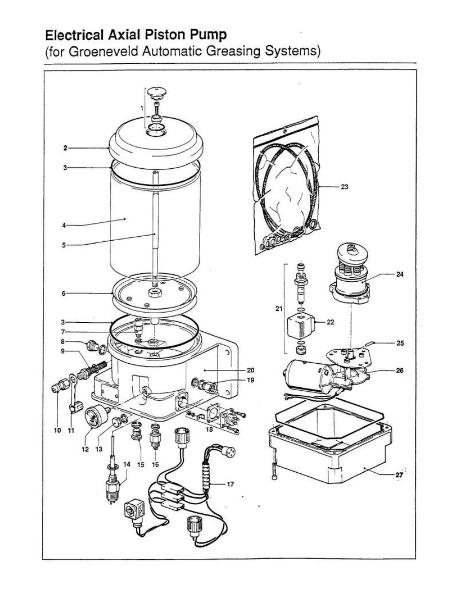
The electric axial pump is activated by the electronic timer. The grease will be pumped from the
reservoir (4) out through the main line (19) to the injector manifolds. The pump remains in operation
throughout the entire cycle period. This cycle time is usually 3 minutes when a standard Groeneveld
electronic timer is used. The normally open return valve (21) is closed by the solenoid (22), at the
same time as the pump is turned on, to close off a return passage to the reservoir. The pump then
builds up grease pressure in the pump and main lines during the cycle. When the pressure reaches 95
bar the pressure relief valve (7) opens, allowing some of the grease to flow back into the reservoir.
Maximum grease pressure is, therefore, limited to 95 bar. The standard version is fitted with a 70 bar,
normally open, pressure switch (16). After 70% of a cycle is complete the timer checks to see if the
pressure switch closed. If during a greasing cycle, the grease pressure does not rise above 70 bar to
close the switch, the electronic timer will sound an alarm (or turn on a warning light – depends on the
type of timer). At the end of a cycle, the timer turns off the power, the pump stops, the return valve
opens and grease in the main line flows back to the reservoir. With the grease pressure dropping to
zero, the injectors can refill themselves for the next cycle.
An optional grease level indicator (14) will also provide a signal to the timer and result in an alarm
signal if the grease in the reservoir gets too low.
On the left side of the pump, behind the filling connector (10) there is a tapped hole in the housing for
air venting and grease overflow. When filling the reservoir with grease, the air above the follower
plate escapes through the hole in the center guide rod (5) which is connected to that tapped hole. If too
much grease is put into the reservoir, causing the follower plate to rise above the ‘maximum line’ then
the excess grease will escape out through that hole in the center guide rod and it will come out of the
vent hole.
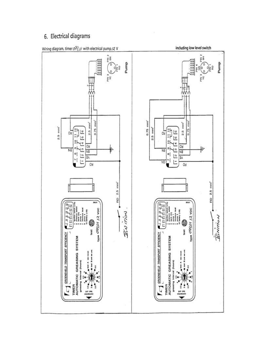
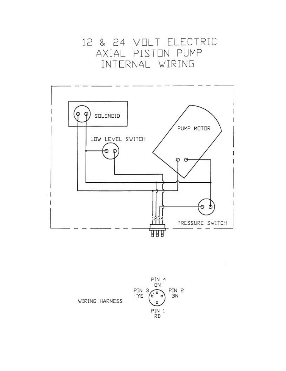
The Pump is wired for a low level switch to pin #4. A low level switch is optional and
added only when the customer requests it.
Wyszukiwarka
Podobne podstrony:
BANK CENTRALNY I JEGO FUNKCJE
Bank centralny 5
Magazyny i centra logistyczne
Europejski Bank Centralny
Bank centralny
Centralne ogrzewanie id 109800 Nieznany
400 man
man ar900
Kaniulacja żył obwodowych i centralnych u noworodków
BANK T02 S Bank Centralny
Przegląd układu tłokowo – korbowego silnika MAN B&W – L 2330 H
Procol Harum The Dead Man's Dream
43. de Man, teoria literatury!!!
Centra Urazowe nie zastąpią SORu, MEDYCYNA, RATOWNICTWO MEDYCZNE, BTLS+chirurgia
elektryka, Kierunki studiów, Architektura, Materiały do nauki=), Budownictwo, Segregacja tematyczna,
Centralka MCR OMEGA, BHP, Instrukcje-Obsługi
więcej podobnych podstron