
Mounting and operating
instructions
SILO SCALE 8to
Code Nr. 99 97 0704
Edition 08/97 M 0704 GB


Thank you very much for your confidence !
You are now the proud owner of a new Big Dutchman
Silo scale 8 t
We are convinced that you will be extremely satisfied with it.
EC Declaration of Conformity
We declare that the design and model of the machine described above, marketed by
ourselves, fully complies with the health and safety requirements of the relevant EC
Directive.
Guarantee Declaration
This machine is guaranteed in accordance with the Big Dutchman International
GmbH General Conditions of Sale for customers in Germany and the Big Dutchman
International GmbH International Conditions of Sale for customers not resident in
Germany.
Note
To ensure that your new equipment will always function properly and efficiently and
to ensure your personal safety, would you be kind enough to:
Study this manual thoroughly and take particular note of the warning and
safety instructions before starting up the machine for the first time.


Table of contents
Page 1
Manual Silo scale 8 t
Edition: 08/97
M 704 GB
Table of contents
1 INTRODUCTION
3
1.1 Symbols
3
1.2 Special safety instructions
3
1.3 General safety instructions
3
1.4 Electrical installations
3
1.5 Maintenance
4
1.6 Ordering spare parts
4
1.7 Liability
5
1.8 Disorders due to power failure
5
1.9 First aid
5
1.10 Copyright
5
1.11 Waste disposal
6
2 SYSTEM DESCRIPTION
7
3 TECHNICAL DATA
8
3.1 Weighing indicator WA991 (Code No. 20 00 3364)
8
3.2 Weigh bar WB 1600 (Code No. 20-00-3351)
9
3.3 Mounting set for WB 1600 under outside silo
10
4 MOUNTING INSTRUCTIONS
11
4.1 Assembly of WB 1600 under silo leg
11
4.2 Connection of the weigh bars
12
4.3 Connection of the weighing indicator
13

Table of contents
Page 2
Manual Silo scale 8 t
Edition: 08/97
M 704 GB
5 OPERATING INSTRUCTIONS
15
5.1 Software settings
15
5.2 Functions
16
5.3 Entering the quantity to be metered in / out - OP-Code -
17
5.4 Error messages
19
6 SPARE PARTS LIST
20
1 Introduction
Page 3
Manual Silo scale 8 t
Edition: 08/97
M 704 GB
1 Introduction
1.1 Symbols
Upon reading this manual you will come across the following symbols:
Warning against dangerous electric tension
1.2 Special safety instructions
Caution This sign indicates risks or insecure procedures possibly
leading to injuries or material damage.
)
Note
This sign indicates notes leading to an effective, economic
and environmentally-conscious handling of the installation.
1.3 General safety instructions
All established safety precautions and other generally accepted safety regulations
and medical references have to be followed.
Please check safety and function control devices to ensure safe and accurate
operation:
• before putting into operation
• at adequate time intervals
• after modifications or repairs.
Follow the directions of the power and water supply companies.
1.4 Electrical installations
All kind of work going beyond the maintenance scope of the equipment are to be
carried out only by a specialist.
Carry out all kinds of work at the device with disconnected electric power supply
cable.
1 Introduction
Page 4
Manual Silo scale 8 t
Edition: 08/97
M 704 GB
Check the electrical wiring and cables for recognisable damage before putting the
device into operation.
Replace damaged wiring and cables, before that, do not take the device into
operation again.
Let damaged or broken plugs be replaced by an electrician.
Do not pull the plug from a socket at the flexible cable.
Covering electrical motors can cause high temperatures so that fire results and the
working means can break down.
1.5 Maintenance
Before working on the electrical installation always disconnect power
supply!
The assembly may only be carried out by persons who are competent and can
guarantee a proper repair because of special training or their knowledge and
practical experiences with the unit.
Repair, maintenance and cleaning operations as well as the removal of functional
disorders may generally only be carried out when the drive is turned off and the
motor is in a standstill.
Only work with appropriate tools; in case of possible danger to hands, use protective
gloves.
After any repair works, the user has to check the proper functioning of the unit or
machine. He may only take the device into operation, when all protective systems
have been put into place again.
Spare parts have at least to correspond to the technical requirements fixed by the
producer of the device. This requirement can be met for example by original spare
parts.
1.6 Ordering spare parts
)
You can find the exact description of the parts for ordering spare parts by
means of the pos. no. in the spare parts list.
Indicate the following for ordering spare parts:
• Code No. and description of the spare part or
•
Pos. No. with description and manual no. in case of parts that are not encoded
• Invoice No. of original invoice
• Current supply, e.g. 220/380V - 3 Ph. - 50 Hz.

1 Introduction
Page 5
Manual Silo scale 8 t
Edition: 08/97
M 704 GB
1.7 Liability
The manufacturer is not responsible for any damages of the machine resulting from
unauthorised changes done by the user.
1.8 Disorders due to power failure
We recommend the installation of warning systems for a better control of your
production units. By this, you protect the birds and thus your own economical health.
In case of power failure, an emergency power-generating set should automatically
supply the system with power.
Emergency power units with universal transmission for connection to a tractor are
also suitable. For further information please contact your property insurance.
1.9 First aid
For the case of an accident, unless specified otherwise, a first-aid kit must always be
available at the place of work. Material taken out and used is to be replaced
immediately.
If you need help, describe the accident as follows:
• where it happened
• what happened
• the number of persons injured
• what danger of injury
• who is passing the message ! (your data)
1.10 Copyright
This manual is subject to copyright. The information and drawings included in this
manual shall not be copied without the manufacturer's consent, nor shall it be used
for anything other than the designated use. It shall also not be given to third parties.
The contents of this manual can be altered without prior notice.
If you find mistakes or unclear information in this manual, please do not hesitate to let
us know.
All trade marks mentioned or shown in the text are trade marks of their respective
owners and are recognised as patented.

1 Introduction
Page 6
Manual Silo scale 8 t
Edition: 08/97
M 704 GB
Copyright 1997 by Big Dutchman
For further information please contact:
Big Dutchman International GmbH
D - 49360 Vechta, Germany
P.O. Box 1163
Phone +49 (0)4447/ 801-0, Telex: 25510 big d, Fax: +49 (0)4447/ 801-237.
1.11 Waste disposal
After finishing the assembly of this installation, dispose of the packing material and
remains which do not need to be further used according to the legal provisions for
recycling.
After putting out of action of the installation, dispose of the component parts accor-
ding to the legal provisions for recycling.
2 System description
Page 7
Manual Silo scale 8 t
Edition: 08/97
M 704 GB
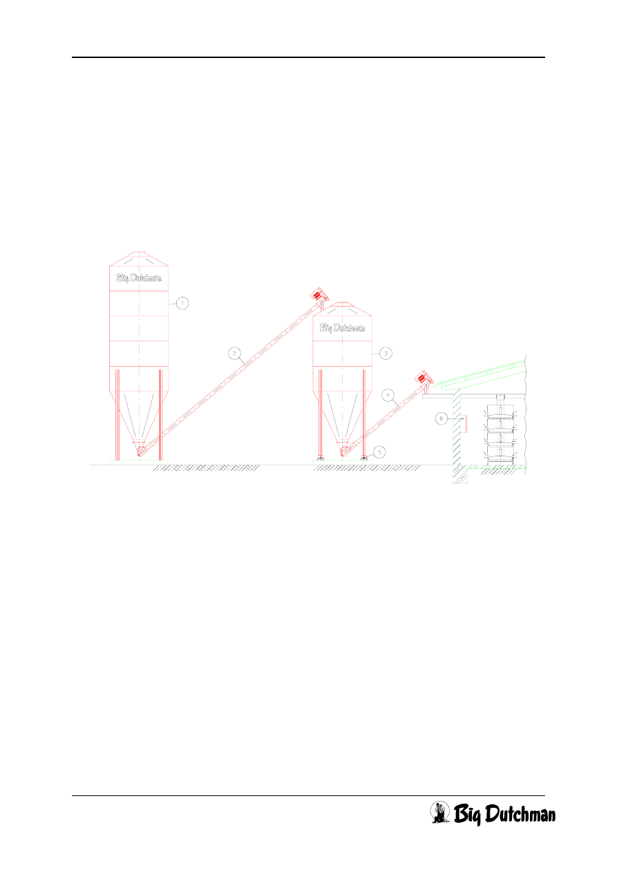
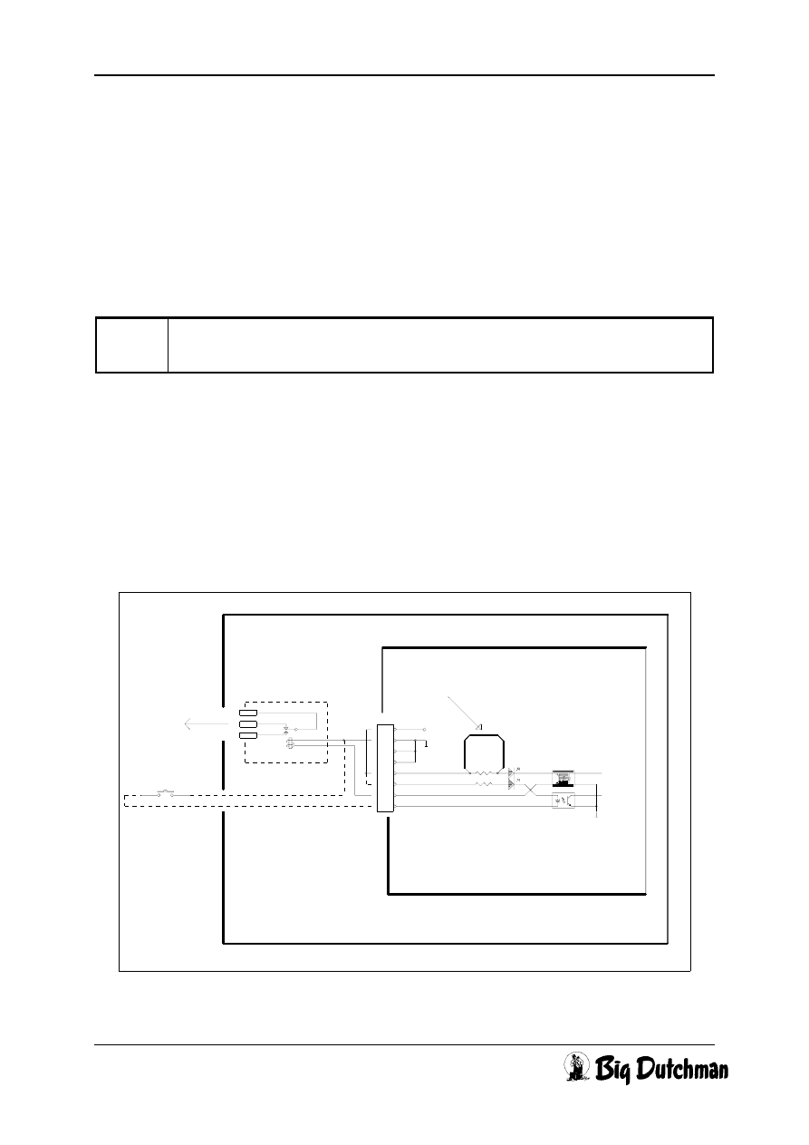
2 System description
The silo scale can weigh a predetermined quantity of feed from the storage silo into
the day silo.
Silo scale 8 t, 4 pt. for day silo
Code No. 20-00-3450
Pos. Description
1
Storage
silo
2
Conveying
auger
3
Day
silo
4
Conveying
auger
5
Weigh
bars
6 Weighing indicator WA991
3 Technical data
Page 8
Manual Silo scale 8 t
Edition: 08/97
M 704 GB
3 Technical data
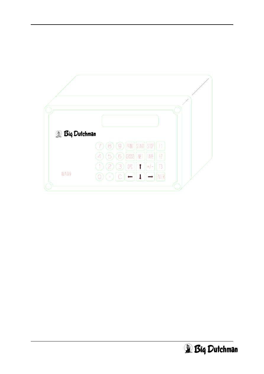
3.1 Weighing indicator WA991 (Code No. 20 00 3364)
Current supply:
230 V - 15 % + 10 %
50/60 Hz
115 V - 15 % + 10 %
50/60 Hz
Connection:
Full bridge weigh bars type WB (all weigh bars are connected
in
parallel)
internal zero point potentiometer
external clock for start of filling
conveying auger via relay contact
Display
8 x 7-Segment LED
Keyboard:
7 x 4 touch-sensitive keyboard
Software:
240 WP99-1, version 1.06, edition 29.08.96 or higher
Housing:
cast iron, IP55, with 6 PG screw unions
3 Technical data
Page 9
Manual Silo scale 8 t
Edition: 08/97
M 704 GB
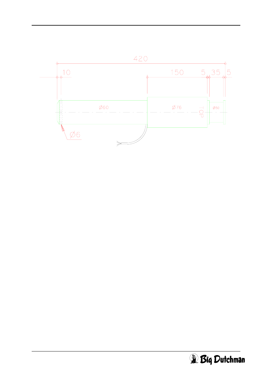
3.2 Weigh bar WB 1600 (Code No. 20-00-3351)
Capacity:
2,000 kg
Precision: 1
%
Impedance: 350
Ω
Connection cable:
10 m
Weight: 10
kg
3 Technical data
Page 10
Manual Silo scale 8 t
Edition: 08/97
M 704 GB
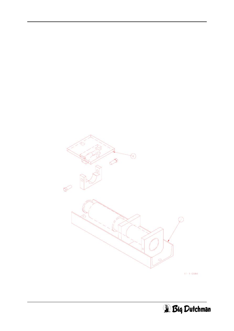
3.3 Mounting set for WB 1600 under outside silo
The mounting set for WB 1600 (Code No. 20-00-3457) comprises the following
parts:
Code No.
Pcs
Description
20 00 3455
1
Bottom plate galv. WB1600 under silo
99 50 3898
2
Express-anchor EXA 12/15 galv.
99 10 3903
1
Hexagon head screw M5x80 DIN 558 galv.
99 20 1033
1
Self-locking counter nut M5 DIN 985-6 galv.
20 00 3459
1
Pressure plate for WB1600 under silo
4 Mounting instructions
Page 11
Manual Silo scale 8 t
Edition: 08/97
M 704 GB
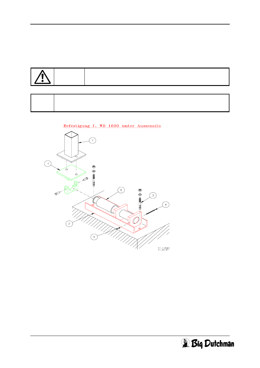
4 Mounting instructions
4.1 Assembly of WB 1600 under silo leg
Caution
During the installation of weigh bars, observe and follow the
local building regulations.
)
The four weigh bars have to be horizontal to the floor. The word TOP on
the weigh bar has to point upwards!
Pos. Code
No.
Description
1 20 00 3459
Pressure plate (2) for WB1600 under silo
2 20 00 3455
Bottom plate (1) galv. WB1600 under silo
3 99 50 3898
Express-anchor EXA 12/15 galv. (drill hole
∅ 12 mm)
4 99 10 3903
Hexagon head screw M5x80 DIN 558 galv.
5 99 20 1033
Self-locking counter nut M5 DIN 985-6 galv.
6 20 00 3351
Weigh bar WB 1600
7
Silo
leg
4 Mounting instructions
Page 12
Manual Silo scale 8 t
Edition: 08/97
M 704 GB
• The screw connection between silo leg and pressure plate has to be adapted to
the respective type of silo, which means that holes have to be drilled according to
the type of silo.
The size and type of fixing screws also have to be adapted to the type of silo.
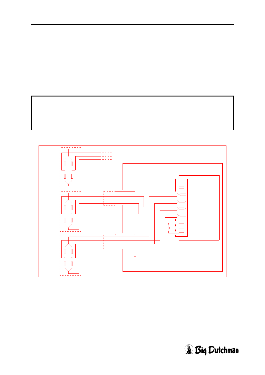
4.2 Connection of the weigh bars
)
All weigh bars are connected in parallel. If the cable to the weigh bars is
not sufficiently long, all cables have to be guided into a branch box, to be
connected in parallel and to be connected to the weighing indicator by
means of a common cable.
BEIGE
BRAUN
BLAU
SCHWARZ
+
-
GND
P3
BEIGE
#3
BRAUN
BLAU
SCHWARZ
O+
I+
I-
WA99
PRINTBOARD
O-
CH
+
-
#2
BEIGE
BRAUN
CT
CCH
CHASSIS = GND
BLAU
SCHWARZ
+
-
#1
WA99 GEHAEUSE
4 Mounting instructions
Page 13
Manual Silo scale 8 t
Edition: 08/97
M 704 GB
4.3 Connection of the weighing indicator
The WP99-1 software comprises a software which can be used for silo as well as for
container scales. This software permits weighing in and metering out of a component.
Hardware requirements:
Applied software: 240 WP99-1, version 1.06, edition 29.08.96 or higher
)
When an update is carried out by a lower version after version 1.06, all
data have to be entered anew. For deleting all existing data use OPC 33.
• Install a relay which is switched from the Tx-output. This relay then switches the
contactor for the auger motor. Only charge the relay with max. 50 V AC/DC and 5
A.
• Solder a bridge above the resistance R39 on the component side of the board
(see diagram).
Wire shorting R39
E+
E+
1
2
3
4
5
6
7
8
P2
4
3
5
1
2
Relay
-9-
-1-
To
Motor
(optional)
Ext. Start
-5-
E-
A1/Tx+
GND
R39
OUT
1
2
4
3
1
2
4
3
GND
IN
B1/Rx+
A2/Tx-
B2/Rx-
WA99 Printboard
File : BATCH.SCH (Rev. : 31/08/94)
WA99 Enclosure
• The wire for external start may be max. 20 m.
4 Mounting instructions
Page 14
Manual Silo scale 8 t
Edition: 08/97
M 704 GB
Caution
Do not put any voltage on the relay contact until
• the appliance No. 5 has been entered
• the DIP-switches SW3-6 (A) - 10 (D) have been switched
into OFF position
• the Reset-button has been pushed.
5 Operating instructions
Page 15
Manual Silo scale 8 t
Edition: 08/97
M 704 GB
5 Operating instructions
5.1 Software settings
The entry for the silo scale is done via OPCode 1, which is described in the following.
This code is automatically available, as soon as the appliance No. 5 has been
entered.
To be able to use the WA99 as silo scale, the following software setting is required:
• Put DIP-switches SW3-1 to SW3-10 into OFF position.
• Put DIP-switches SW3-6(A) and SW3-7(B) into ON position and push the Reset
button.
During runup, information on the used software or the settings are indicated.
• Enter appliance No. 5 under OPC 70.
• Enter the calibration No. by means of one of the following methods:
with OPC 71, standard calibrations can be chosen
with OPC 79, manual calibration can be carried out
with OPC 86, known data of a calibration can be entered.
• Enter the filter characteristics by OPC 65
• Enter zero point under OPC 72
• Put DIP-switches SW3-6 (A) and SW3-7 (B) into OFF position and push the Reset
button.
During runup, information on the appliance No. (d = 005) and the calibration
No. (c = xxx) are indicated.
• Push Reset button to finish.
Caution
If the error message -Err95- is indicated at the end of the
runup, push the F1-button under OPC 97 (after putting DIP-
switches SW3-6(A) and SW3-7(B) into ON position and
pushing the Reset button).
Every error message can be deleted by means of pushing
the OPC-button.
)
If data have been entered by OPC, after entering this OPC it can be left
again by pushing the OPC button and it is indicated as described in 5.2.
5 Operating instructions
Page 16
Manual Silo scale 8 t
Edition: 08/97
M 704 GB
5.2 Functions
The silo scale has different functions:
a) Weigh a predetermined weight in (U), i.e. a predetermined quantity is
weighed into an empty container, which is located on a scale.
Sign for weighing in ─┘
b) Meter a predetermined weight out (∩), i.e. a predetermined quantity is
metered out of a full container which is located on a scale.
Sign for metering out ─┘
The system to be used can be chosen by the F1-button.
c)
Weigh in a quantity up to a certain weight on the scale (r), i.e. the possibly
remaining quantity is taken into account. If this value is already reached
upon starting the weighing-in process, starting is not carried out.
Sign for considering remaining quantity ─┘
Whether this function is used, can be chosen by the F2-button.
r = with taking into account of remaining quantity
blank = without taking into account of remaining quantity
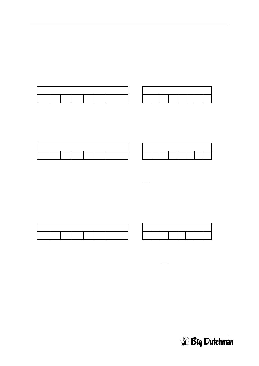
Enter Display
U
Enter Display
F1
∩
Enter Display
F2
r U
5 Operating instructions
Page 17
Manual Silo scale 8 t
Edition: 08/97
M 704 GB
d) Meter a predetermined weight out (∩), i.e. a predetermined quantity is
metered out of a full container which is located on a scale.
Sign for considering remaining quantity ─┘
The difference to b) is that the scale does not allow a negative scale value, i.e. if the
scale indicates a smaller value than the quantity to be metered out, the error
message -Err65- is prompted.
The container then does no longer contain a sufficient quantity.
5.3 Entering the quantity to be metered in / out - OP-Code -
For example: 1500 kg are supposed to be weighed into a silo and the remaining
quantity to be taken into account.
Enter for example 1500 kg
It is supposed to be weighed into the silo.
Sign for weighing in ─┘
Enter Display
F2
r
∩
Enter Display
1 OPC
0 0 0 0 0
∩
Enter Display
0 1 5 0 0 ENTER
0 1 5 0 0
∩
Enter Display
F1
0 1 5 0 0 U
5 Operating instructions
Page 18
Manual Silo scale 8 t
Edition: 08/97
M 704 GB
The remaining quantity is supposed to be taken into account.
Sign for considering remaining quantity ─┘
Back to weight indication, for example 32 kg are on the scale.
Start „Metering in“
this sign flashes ─┘
• Now it is counted down from the indicated value to zero, i.e. the indicated value is
the quantity which is metered in. During metering in, the sign flashes at the very
right of the display. If the value is zero, the display automatically changes to the
scale value.
• If the settings are not changed, metering in can directly be started by pushing the
START button.
• Starting of metering in can also be carried out over an externally connected clock
(see diagram).
• The entry for metering out is done respectively.
Enter Display
F2
0 1 5 0 0 r U
Enter
Display
shows
OPC
0 0 0 3 2
Enter
Display
shows
START
0 1 4 6 8 U

5 Operating instructions
Page 19
Manual Silo scale 8 t
Edition: 08/97
M 704 GB
5.4 Error messages
All error messages in connection with the silo scale (appliance No. 5) are indicated
by a flashing -Err xx-- and can be deleted by pushing the [OPC] button, after the
error has been corrected.
Error No.
Description
65
During metering out (see OPC- 1), the quantity to be metered out is no
longer existing on the scale.

6 Spare parts list
Page 20
Manual Silo scale 8 t
Edition: 08/97
M 704 GB
6 Spare parts list
For ordering spare parts please use the code numbers or position numbers of the
respective component parts listed in the individual sections.
Wyszukiwarka
Podobne podstrony:
29 Zdolność pracownicza
KOMPLEKSY POLAKOW wykl 29 03 2012
6 Wielki kryzys 29 33 NSL
2Ca 29 04 2015 WYCENA GARAŻU W KOSZTOWEJ
wyklad 29 i 30 tech bad
plik (29) ppt
4 JM02 JS05 24 29 złamania
2001 11 29
29 temat(1)
ATMiA 29 1 3 id 71755 Nieznany (2)
29
23 29
2001 12 29
29 35
więcej podobnych podstron