This article was downloaded by: [Politechnika Warszawska]
On: 18 October 2014, At: 10:28
Publisher: Taylor & Francis
Informa Ltd Registered in England and Wales Registered Number: 1072954 Registered office:
Mortimer House, 37-41 Mortimer Street, London W1T 3JH, UK
International Journal of Computer
Integrated Manufacturing
Publication details, including instructions for authors and subscription
information:
http://www.tandfonline.com/loi/tcim20
Conceptual design of a shop floor control
information system
Dah-Chuan Gong & Yueh-Wen Hsieh
Published online: 08 Nov 2010.
To cite this article: Dah-Chuan Gong & Yueh-Wen Hsieh (1997) Conceptual design of a shop floor control
information system, International Journal of Computer Integrated Manufacturing, 10:1-4, 4-16, DOI:
http://dx.doi.org/10.1080/095119297131147
PLEASE SCROLL DOWN FOR ARTICLE
Taylor & Francis makes every effort to ensure the accuracy of all the information (the
“Content”) contained in the publications on our platform. However, Taylor & Francis, our
agents, and our licensors make no representations or warranties whatsoever as to the
accuracy, completeness, or suitability for any purpose of the Content. Any opinions and views
expressed in this publication are the opinions and views of the authors, and are not the views
of or endorsed by Taylor & Francis. The accuracy of the Content should not be relied upon and
should be independently verified with primary sources of information. Taylor and Francis shall
not be liable for any losses, actions, claims, proceedings, demands, costs, expenses, damages,
and other liabilities whatsoever or howsoever caused arising directly or indirectly in connection
with, in relation to or arising out of the use of the Content.
This article may be used for research, teaching, and private study purposes. Any substantial
or systematic reproduction, redistribution, reselling, loan, sub-licensing, systematic supply, or
distribution in any form to anyone is expressly forbidden. Terms & Conditions of access and use
can be found at

Conceptual design of a shop ¯ oor control
information system
DAH-CHUAN GONG and YUEH-WEN HSIEH
Abstract.
This paper presents a conceptual model for
guiding the integrated design and implementation of a
shop
¯ oor
control
information
system
(SFCIS) in
manufacturing. Issues discussed include control decisions,
information ¯ ow, and communication message passing, but
not the content of speci® c shop ¯ oor databases. A bidding
system is assumed for control of job dispatching and route-
ing. Information ¯ ow is described using IDEF
0
. Through an
object- oriented (O± O) approach, the IDEF
0
description is
extended to a message passing timing diagram, similar to the
manufacturing message speci® cation (MMS), to represent
the communication. Also included is an example to illustrate
the proposed SFCIS development procedure.
1. Introduction
Under pressure to reduce production cost, improve
quality, and respond to variable market demands,
industry worldwide is rapidly adopting automation.
Automation requires more than a sequential control
of the production process. It requires coordinating the
production activities on the shop ¯ oor (where produc-
tion resources are supplied), and tracking the system
status to smooth the production. Shop ¯ oor control
(SFC) is crucial in a contemporary manufacturing
system.
The responsibilities of SFC primarily involve job
scheduling, progress monitoring, status reporting, and
corrective actions (Bauer et al. 1991, Melnyk and Carter
1987). SFC has to rapidly re¯ ect the current system
status to allow job processing to be controlled in a real-
time mode. However, the manufacturing system
behaviour, which is an accumulation of status in
time, is highly dependent on the control system
architecture, control function classi® cation, and
allocation of controls to di erent control levels (i.e.
control allocation). In other words, an integrated study
of the control function, architecture, and activities
should be done at the design stage of a manufacturing
shop ¯ oor control system. Furthermore, the control
`message passing’ system is another issue that should
not be ignored, because it is based on the designed
control system and is essential to the execution of
control decisions.
In the past, most research focused on one or some
of the following issues: manufacturing functions,
control architectures, activity descriptions, message
types, and communication (Bauer et al. 1991, Biemans
1990, Browne 1988, Dilts et al. 1991, Jones and McLean
1986, Melnyk and Carter 1987, Lin and Solberg 1992,
Veeramani et al. 1993, Y ep et al. 1993). However, the
message passing content, target (destination), and
timing, deeply a ect the use of shop ¯ oor resources
and are highly related to the selected control
architecture, control function classi® cation and alloca-
tion. Modelling an SFCIS requires a comprehensive
approach to integrate the design of the issues con-
sidered above. In fact, to describe such a conceptual
model is the goal of this paper.
An SFCIS is in charge of data collection, classifica-
tion, management, analysis and message passing on the
shop ¯ oor. It must cooperate with the control system
to execute production activities, deliver high- level
decisions, and monitor the production status to
accomplish the required job processing on time. As
shown in Figure 1, the SFCIS development addresses
the basic issues, which correspond to control,
information, and communication, respectively.
A generic `part life cycle’ model is proposed and
used as the basis for a corresponding IDEF
0
model that
describes both material ¯ ow and information ¯ ow. The
IDEF
0
model is used to develop an object- oriented
representation of activities and information, and
a general message passing timing diagram. This
diagram, which is in a form similar to the MMS
0951-192X/97 $12.00
1997 Taylor & Francis Ltd
INT. J. COMPUTER INTEGRATED MANUFACTURING,
1997,
VOL.
10,
NO.
1-4, 4± 16
Authors
: Dah-Chuan Gong and Yueh-Wen Hsieh, Department of Industrial
Engineering, Chung-Y uan University, Chung-Li, Taiwan 320.
Downloaded by [Politechnika Warszawska] at 10:28 18 October 2014
(E.I. Association, 1989), delivers a channel possibly to
be further implemented in a physical system.
2. Literature review
2.1. Control architectures
Rapid growth of technology in computing and
communication has created a wide range of possibilities
in designing control architectures. As described in
Dilts et al. (1991), there are four basic forms of control
architectures: centralized, hierarchical, modi® ed
hierarchical, and heterarchical. The centralized
control architecture employs a centralized computer
or controller to manage and maintain the records of all
planning and information processing functions.
Machines execute the commands released from the
centralized computer and then feed back the
execution results.
In a strict hierarchical architecture, there is a
rigid master/slave relationship between two adjacent
levels of controllers. Peer communication between
controllers at the same levels is not allowed. Within
the hierarchy of controllers, a superior sees only
its immediate subordinates and not the subordinates
of
its
subordinates.
This
concept
gives each
controller a certain control authority within its
realm.
Basically, a modi® ed hierarchical control architecture
is similar to a strict hierarchical architecture, except
that it allows peer communication. With this feature,
the modi® ed control architecture has a loose master/
slave relationship between control levels. A superior is
responsible for initiating a sequence of activities. The
subordinates are able to cooperate to complete these
activities in sequence.
A heterarchical control architecture is also called a
distributed or cooperative control architecture. One
major feature of this architecture is to pursue the
full local autonomy and a cooperative approach to
global decision making. There are no master/slave
relationships between control components. Parts and
resources are referred to as entities with intelligent
(software) agents (Du
e and Piper 1986, Du
e et al.
1988). Cooperation between entities is implemented
via a negotiation and bidding procedure to accomplish
tasks.
The heterarchical control architecture permits
signi® cant ¯ exibility in operation. However, the price
of this architecture is the heavy communication
burden. Today, the computer technology has been
tremendously improved. The control negotiations are
processed at very high speed. The communication
Conceptual design of a shop ¯ oor control information system
5
Figure 1. An SFCIS development structure.
Downloaded by [Politechnika Warszawska] at 10:28 18 October 2014
burden can be reduced.This architecture can be applied
in a relatively complicated manufacturing system.
Furthermore, the bidding processes mostly corre-
spond to control decision makings. Simple bidding
can strictly simplify the communication. However, the
entire manufacturing system will be operated effec-
tively only when good bidding policies are determined.
2.2. System description methodologies
There are a variety of system description
methodologies for di erent purposes and problem
domains. Examples include data ¯ ow diagrams (DFD),
Jackson diagrams, entity-relation, Petri nets, and the
integrated computer aided manufacturing (ICAM)
DEFinition (IDEF) family. For developing functional
and information models, IDEF has been considered
more appropriate for the manufacturing environment
(Pandya 1994).
The most popular and mature tools of the IDEF
family cover IDEF
0
, IDEF
1
/IDEF
1x
, and IDEF
2
. IDEF
0
was ® rst developed by the US Air Force on its ICAM
programme. The structural analysis methodology of
IDEF
0
allows one to present complex manufacturing
functional relationships hierarchically.
Figure 2 illustrates blocks or units of an IDEF
0
model. Each block corresponds to an activity to be
performed. Four types of arrows are associated with a
block. They are input, output, control, and mechanism,
respectively. A block also indicates the boundary of an
activity. It can be further broken down into several
sub- activities. These sub- activities, located at a lower
level, must present the content of their superior
activity consistently. Related blocks at the same level
are connected in a network. Connections between
blocks represent ¯ ows of control, information, or
materials used, required, or processed between
activities.
The IDEF
0
methodology has been widely used.
Gong and Lin (1994) have demonstrated it as a
starting tool for control determination, classi® cation,
and allocation. Bauer et al. (1991) have applied it to
present the shop ¯ oor control functions and related
information system. The IDEF
0
decomposition process
has also been used as a basis for building up a
manufacturing information model, as given in Kim
et al. (1993).
The O± O method was created from mapping the
software IC to objects (Lee and Sen 1994, O’Grady and
Seshadri 1992). When the O± O method is selected, the
system of interest should be described in terms of
objects. Each object is a discrete and easily identi® ed
entity. It can correspond to a device or a conceptual
control mechanism (software). Attributes contain the
object’s data. Objects with similar characters are
clustered as a class. Objects interact by message
passing. These interactions map intuitively to the
physical system interactions. As such, message passing
should serve as a basis for checking the control
information ¯ ow validity and for aiding system
implementation.
As described in Booch (1994) and Rumbaugh et al.
(1991), the O± O characteristics include classi® cation,
information hiding and encapsulation, inheritance
and polymorphism. During execution, each object’s
attributes and its internal operating scheme are
encapsulated. The object’s internal data cannot be
retrieved directly except via a speci® c channel
supplied by the object. This restriction simpli® es
each individual object behaviour by focusing on its
interface only. Several surveys of applying this O± O
concept in manufacturing can be found in Lee and Sen
(1994) as well O’Grady and Seshadri (1992).
2.3. Information system models
In 1994, Ngwenyama and Grant applied the O± O
method to develop an information model of the
computer integrated manufacturing (CIM) system.
They described the necessary techniques and steps
from the development stage to the implementation.
Related to their work, the SFC should locate at the
operational, not planning, level. The SFC information
analysis should focus on discussions of the necessary
data types, information ¯ ow directions and inter-
relationships between various information types on
the shop ¯ oor.
D.-C. Gong and Y.-W. Hsieh
6
Figure 2. An IDEF
0
diagram.
Downloaded by [Politechnika Warszawska] at 10:28 18 October 2014
Y ep et al. (1993)have also developed an information
¯ ow model, but on a hierarchical control architecture.
Client and server positions are addressed to two
adjacent control levels. In receiving status reports,
the superior acts as a client and requests information
from its subordinates. Kim et al. (1993)propose an O- O
modelling methodology for a manufacturing informa-
tion system. They point out analysis and design as the
two required stages. The manufacturing system is ® rst
decomposed into functions, represented in terms of a
functional diagram. This diagram is then used for
creating three tables: function, data, and operation to
form the ® nal information relationship diagrams. As a
manner of fact, the IDEF
0
and O± O concept are
tools demanded at the analysis and design stages,
respectively.
2.4. Message passing
In SFC, message passing can never be avoided. It
must deliver data or information to the right places via
the correct protocol. The message itself can be as
simple as a signal to trigger the ¯ ow of control
information. Messages passing between devices, there-
fore, can demonstrate the dynamic behaviour of a
manufacturing system. However, devices may come
from di erent vendors with di erent communication
modes or protocols. Some kind of connection
(messaging) standard is required (Shanmugham et al.
1995). The manufacturing message speci® cation which
is de® ned at the ISO/OSI communication protocol
application layer (ISO 9506) is developed for this
purpose. The MMS provides a communication and
interface standard between devices. It also de® nes the
messages, and the required services along with the
companion standard to accomplish the production’s
execution (Electronic Ind. Asso. 1989). Unfortunately,
the MMS speci® ed message types in a factory are
usually broad. The di
culty of implementing the
MMS standard across many devices may make the
MMS not too popular (Shanmugham et al. 1995).
2.5. Summary
As mentioned in Kim et al. (1993), when designing
an information system, one must ® rst understand the
operations of manufacturing functions and their inter-
relationships. Since information ¯ ow conveys the
system control, the required information types are
identi® ed after the analysis and classi® cation of
control functions. Furthermore, under di erent
control architectures the required messages and fre-
quency are di erent. In a hierarchical architecture,
messages are mostly associated with command or
feedback. The message types concerned are few and
® xed. However, this is not the case in a heterarchical
architecture, where messages are required in the
bidding process.
Generally speaking, the control architecture and
functions, information ¯ ow, and message passing are
three related issues that span from analysis to design.
Their contents are related and overlap. Their
development in time can be depicted as in Figure 3.
Finally, comparison of this paper with a survey of
previous research work is illustrated in Table 1.
Conceptual design of a shop ¯ oor control information system
7
Figure 3. Development sequence of three issues.
Table 1. Comparison of research work.
Control architecture
Control functions
Data/information ¯ ow
Message passing
Related research Dilts
et al
. 1991
Groover 1987
Ngwenyama and Grant 1994
Shanmugham
et al
1995
work
Du e 1990
Melnyk and Carter 1987
E.I. Assoc. 1989
Du e and Piper 1986
Du e
et al
. 1988
Kim
et al
. 1993
Bauer
et al
. 1991
Veeramani
et al
. 1993
Browne 1988
Veeramani 1994
Gong and Kuo 1994
Y ep
et al
. 1993
Gong and Lin 1994
Lin and Solberg 1992
This paper
Gong and Hsieh
Downloaded by [Politechnika Warszawska] at 10:28 18 October 2014

3. Assumptions and system components
A manufacturing system receives inputs (i.e. raw
materials) through an input bu er, transforms the
inputs to outputs (i.e. products) through a set of
production operations, and releases the outputs
through an output bu er. Material, in the form of
jobs (lots, batches, parts, etc.) moves between
production operations by means of a transporter
system or transporters. Machines determine the
physical attributes of material/jobs, other than age
and location. The transporters provide the transforma-
tion of age and location through storage and move-
ment. As far as the manufacturing logistics is
concerned, control decisions associated with material
as it ¯ ows through the manufacturing system should
be addressed. Several assumptions are made as
follows.
3.1. Assumptions
Assumption 1:
The manufacturing system under
consideration is a discrete-parts manufacturing system.
Assumption 2:
Machines have internal processing
locations where parts are processed. There may be
additional bu er locations immediately preceding
and following the machine (i.e. the input and output
bu ers).
Assumption 3:
The capability of each machine, i.e. the
set of operation types that can be performed by this
machine, is given.
Assumption 4:
Each job has a process plan, which is a
sequence of required operations.
Assumption 5:
There are three types of control
decisions (Han and McGinnis 1989):
Induction: accepting new jobs into the unit of control.
Dispatching: selecting from a set of jobs the one to be
processed or transported next, where a simple decision
such as ® rst- come-® rst-serve (FCFS)is used for process
dispatching.
Routeing: selecting from a set of available alternative
destinations the one to which a job is to be sent next.
Assumption 6:
A bidding system with predetermined
rules or regulations is applied for making decisions.
Therefore, machines cooperate and follow a bidding
process to accomplish production operations, as do
the transporters.
Assumption 7:
Other parallel messaging situations are
handled based on tie-breaking rules.
For simplicity, there are a number of issues that we
do not address. We do not consider deterioration or
loss of material; we ignore the logistics of ® xtures or
pallets; and we do not consider the database and
computer networking issues.
3.2. System components
As discussed in Du
e (1990)and Veeramani (1994),
current shop ¯ oor control systems tend to be robust,
¯ exible, reliable, modularized, fault tolerant and
extendible. A distributed (or heterarchical) control
architecture seems to be one preferred architecture.
Its ¯ exibility and extendibility allows suppliers to
rapidly adjust their production to re¯ ect the various
market changes of demands and product types (Du
e
and Piper 1988).
In 1987, Melnyk and Carter identi® ed ® ve shop ¯ oor
control functions: (1) order review/release; (2) detailed
scheduling; (3) data collection/monitoring; (4) control/
feedback; and (5) order disposition. Furthermore, in
Bauer’s model, the control of operational issues within a
manufacturing system is addressed in two layers:
factory coordination (FC) and production activity
control (PAC). The FC system has three modulesÐ
scheduler, dispatcher, and monitorÐ to coordinate the
¯ ow of work between various cells. PAC contains two
additional modulesÐ producer and mover± to execute
operations at resources and the material handling
required between them. In comparison with the
Melnyk model, Bauer functional modules provide a
classi® cation closer to the O± O concept. In this paper,
both the Melnyk and Bauer models are referred to for
reviewing the control activities.
From the part ¯ ow viewpoint, the three control
decisions provide a scenario which displays the result
of processing those models. Work orders in terms
of materials or parts received from the planning
system (e.g. the MRP system) are coordinated and
introduced into the shop ¯ oor as an induction
decision. A part processing may be performed at
alternative places. The routeing decision is required
and determined dynamically through negotiation.
However, when an FCFS or ® xed preference
sequence is applied to select parts in front of a
machine to be processed next, the dispatching decision
becomes redundant. The machine dispatching and
routeing decisions are related or even confounded.
For example, a di erent routeing decision may
accumulate a di erent set of parts in front of a
machine and then lead to a di erent process dispatch-
ing sequence on this machine. To reduce control
complexity, either type of decision can be simpli® ed.
In this paper, a simple dispatching decision such as
FCFS is assumed. Therefore, the dispatching issue will not
be addressed explicitly.
D.-C. Gong and Y.-W. Hsieh
8
Downloaded by [Politechnika Warszawska] at 10:28 18 October 2014
The integration of the IDEF
0
and O± O concept
provides a view of a manufacturing system covering its
physical objects, functions, decisions, and information.
In a heterarchical architecture, decisions come out corre-
sponding to the processing of control functions from the
negotiation among objects. Objects are usually de® ned or
classi® ed based on the real system components such that
the knowledge from a model can be easily delivered to
the reader or for further implementation.
Each object has an agent in charge of its information
processing. The agent can be viewed as a `controller’ of
an object. Associated with the direct physical part ¯ ow,
three types of agent are considered: the part agent,
producer agent, and mover agent. Furthermore, in
accomplishing the bidding process, agents of the
monitor and database are required. A brief description
of these ® ve types of agent is presented in the following:
Part agent : is created once a part is introduced into
the system. Besides corresponding to a particular part,
it also tracks the part status and provides an updated
part information.
Producer agent : corresponds to a machine. It also
can be a tool or ® xture, if necessary.
Mover agent : indicates a robot, conveyer, or auto-
mated guided vehicle (AGV). It may contain informa-
tion such as working space, delivery path, speed, or
service target.
Monitor agent : keeps track of the global domain
status. Three goals tend to be reached from the moni-
tor agent. They are (1) monitoring the ¯ ow of informa-
tion, (2) collecting and analysing local information to
provide accurate global information, and (3) adjusting
the bidding rule or policy from a global view, if
required, to increase the entire system performance.
Database agent : just acts as a regular database. It is
able to store historical system data and maintain global
data such as the bidding rule, which is retrievable by
other agents.
4. Model development
An SFCIS model in the form of IDEF
0
is introduced
in this section. In the model development process, the
production activities of a part production life cycle are
examined to detect the necessary controls and the
object interactions that perform those controls. A
timing diagram is converted by fetching information
from the IDEF
0
model.
4.1. Production activities
A new arrival comes into the system because of an
induction decision. Each part has a process plan that
speci® es a sequence of required operations. If more
than one producer (machine) is able to perform the
same operation, then a production bidding process is
initiated. Once a machine is selected, the part may have
to invoke a bidding process with a set of transporters.
For example in an AGV system, there are multiple
vehicles moving on the common network. A vehicle
dispatching decision (assigning a vehicle to deliver a
part) is made when a part movement is required, and
corresponds to a bidding process between the part and
the AGV system
Each machine is considered to have at least two
bu ers for input and output. A part coming to a
machine can be processed immediately when the
machine is idle. Otherwise, it joins the input queue
and waits to be processed in sequence. Once a part has
acquired an idle machine, a time segment is delayed to
represent part processing. If another operation on this
part is required, a new production bidding process is
initiated to select one machine from a set of candidates
for performing this operation. The activities of
producer bidding, mover bidding and processing
happen recursively until all the operations on a part
have been satis® ed. The ® nal bidding among movers
then starts, if necessary, to deliver the part out of the
system for disposal. The production life cycle scheme
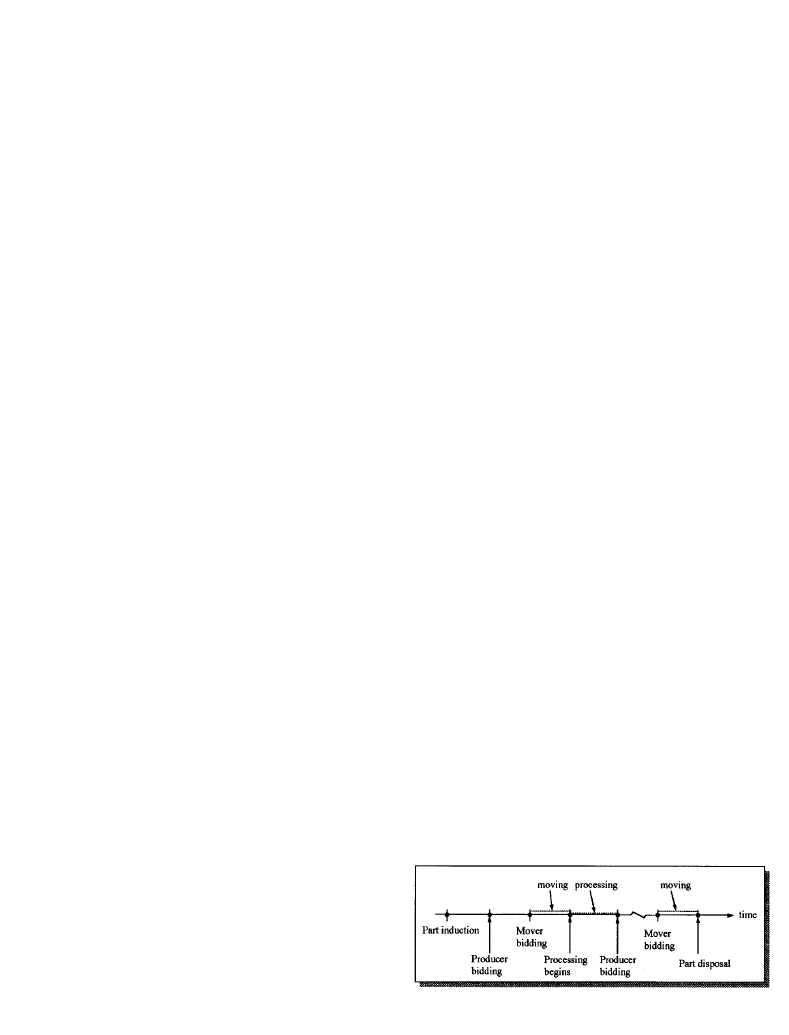
of a part is shown in Figure 4.
Some additional information is revealed in Figure 4.
Each solid black dot denotes an event, or a system status
change. It can be de® ned for a single control function or
for several control functions (or decisions)if they can be
executed in sequence `relatively’ without time delay. A
segment succeeding an event dot represents an activity,
which is enabled only after its event has been triggered.
In brief, certain SFC activities are focused and will
be used as `blocks’ in constructing an IDEF
0
model.
These major activities especially indicate the require-
ment for controls of part production on the shop ¯ oor.
These activities may correspond to the dots and
segments depicted in Figure 4. They also may indicate
an event dot only, if this event contains a control
function which is performed separately. An example is
the machine bidding process. In addition, without the
Conceptual design of a shop ¯ oor control information system
9
Figure 4. The production life cycle scheme of a part.
Downloaded by [Politechnika Warszawska] at 10:28 18 October 2014
monitoring activity, control decisions cannot be made
with proper information. Therefore, the relevant SFC
activities are: (1) task announcement; (2) machine bid-
ding; (3)mover bidding and delivery; (4)task processing;
(5) mover bidding and disposal; and (6) monitoring.
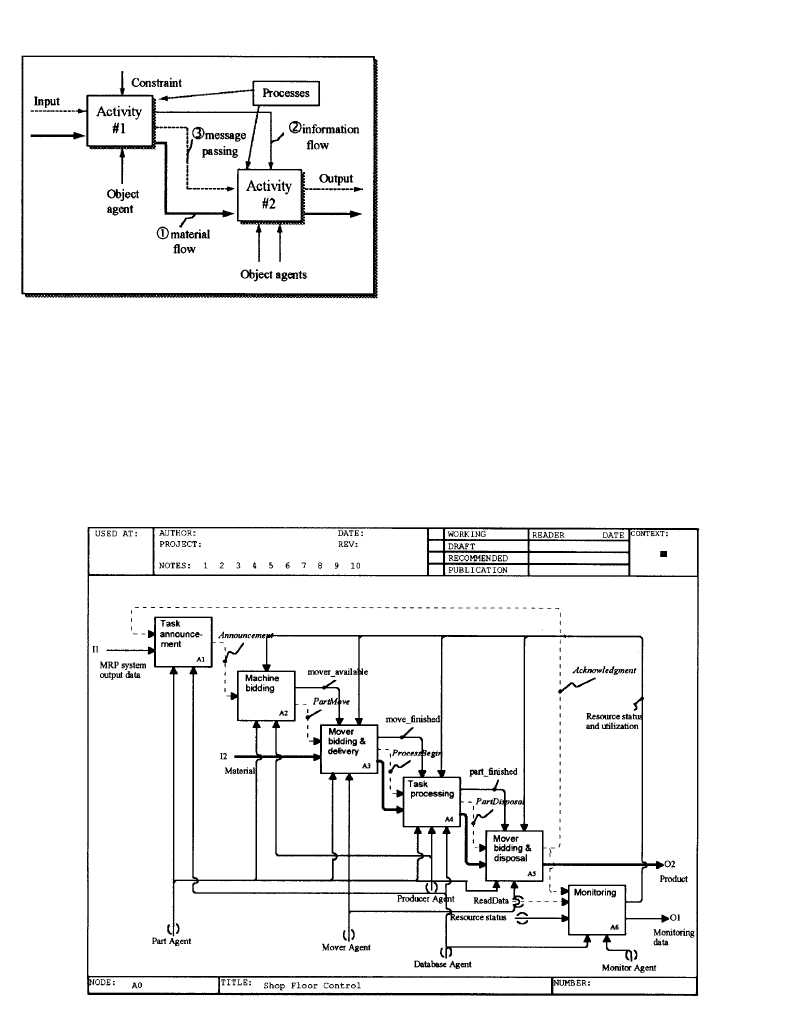
4.2. The SFCIS IDEF
0
model
As discussed in Section 2.2, the selected IDEF
0
methodology allows hierarchical presentation of the
complex manufacturing functional relationships. It
can address the materials and information ¯ ow
explicitly. In order to combine the O± O concept to
construct the desired message passing diagram, some
modi® cation of IDEF
0
has been made. As presented in
Figure 5, three types of lines are applied to replace the
original input and output. The bold line indicates the
material ¯ ow, the thin line is the information ¯ ow, and
the broken line denotes the passing message. The
information output from one block may become the
`control constraint’ of another block. However, message
passing only acts between the input and output of
di erent blocks. Mechanisms, the upward arrows, initi-
ally represent the resources used to perform an activity
block. In Figure 5 they are replaced by the object agents
to show how objects interact.
To create an SFCIS IDEF
0
model, the concerned
blocks are ® rst listed from the part production ¯ ow
view. The bold lines identifying the material ¯ ow are
then drawn. Third, the information ¯ ow lines are
placed where the control information must ¯ ow.
Next, the message passing lines are added to support
the information ¯ ow and the object agents are added
to indicate with whom the interactions happen. An
IDEF
0
model at its level 0 is constructed and supplied
as in Figure 6.
D.-C. Gong and Y.-W. Hsieh
10
Figure 5. Modi® ed IDEF
0
blocks.
Figure 6. An SFCIS IDEF
0
model (A0).
Downloaded by [Politechnika Warszawska] at 10:28 18 October 2014
The major purpose of this paper is to demonstrate
a systematic approach that facilitates construction of
an SFCIS model. Instead of having a drawn- out
presentation, we select only enough level of details to
show how it works. Also, only enough message passing
content is shown. As illustrated in Figure 6, work orders
are output from the MRP system and immediately input
to the task announcement block. The Announcement
message from each part agent to its candidate
producer agents starts a machine bidding process.
Once a producer agent wins a bid, the current infor-
mation of `mover
-
available’ is retrieved to select the
mover agents capable of joining the delivery bidding
process. A PartMove message is further transmitted to
the mover bidding and delivery block (noted as A3) to
indicate the creation of a delivery service request and
the start of a move bidding process.
When a part arrives at its destination, a message
(EndofDelivery, in Figure 8) is released to indicate the
completion of a delivery service. Furthermore,
between a part agent and a producer agent there
exists a sequence of message passing containing a
ProcessBegin signal to start an operation at the block
A4. After processing, a message to initiate the next
activity is sent to block A2 if another operation is
required, or to block A5 if all operations have been
completed. For simplicity, the former situation does
not appear explicitly in Figure 6, but it has been
discussed in detail in Section 4.1 and depicted in
Figure 4. Once a part has completed all the required
operations and has been delivered to an out-bound
location (indicating out of the system), the mover agent
has to forward an Acknowledgement message back to the
A1 block to update the part list information.
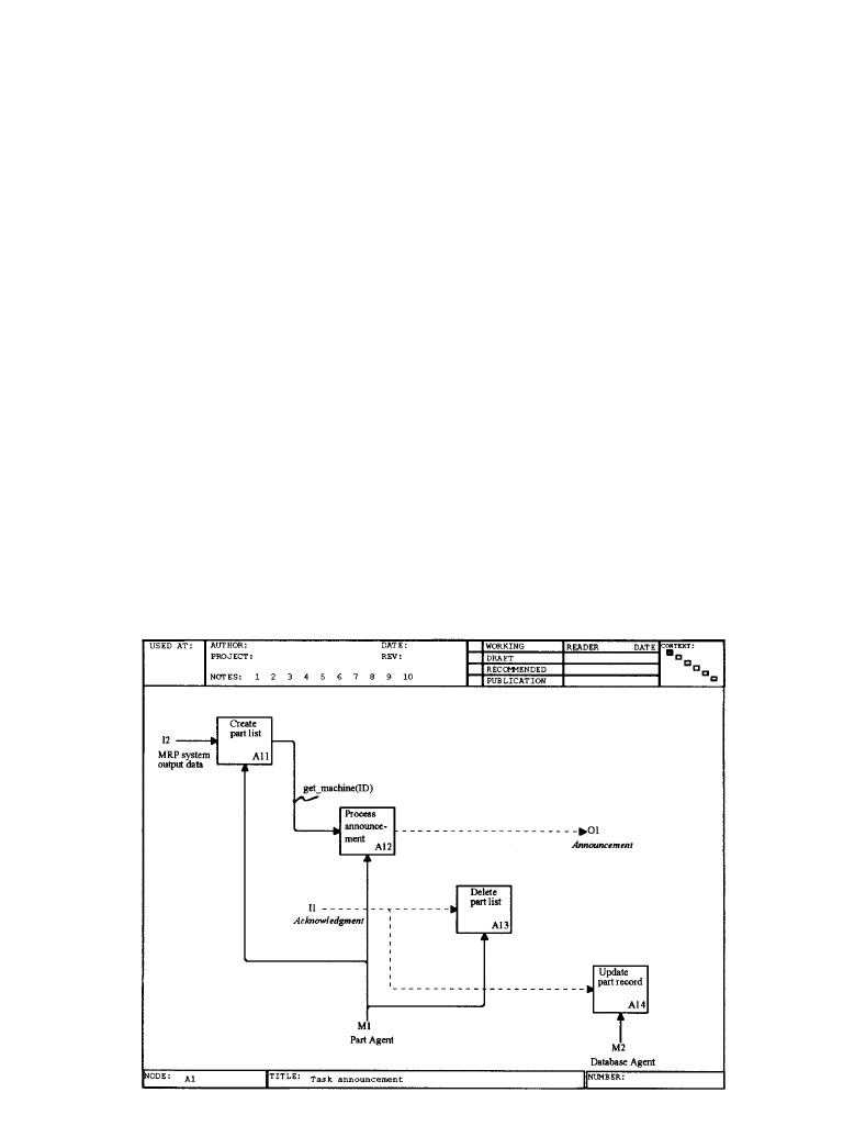
Many inner activities of each block are invisible at
this level. They can be represented at the next level
or further lower levels. As given in Figure 7, the
next level activity blocks of the block task announce-
ment, denoted as A1, include `create part list’,
`process
announcement’, `delete part
list’ and
`update part record’, numbered A11, A12, A13, and
A14, respectively. There are two inputs to the A1 block
and one output from it to another block. To maintain
consistency, exactly two inputs and one output ¯ ow
in or out of blocks A11± A14 from or to their
environment.
In the same manner, decomposition can be
obtained for blocks A2± A6. The details of activity
names and their associated agents and information
are listed in Table 2. There is a design issue of how
deeply to decompose a block. An IDEF
0
model can be
decomposed into blocks that are as detailed as needed.
In this paper, we decompose the model into blocks to
such a level that each block on this level contains only
one type of agent. In this way, information ¯ ow and
message passing can be clearly identi® ed between
Conceptual design of a shop ¯ oor control information system
11
Figure 7. Activities blocks inside A1.
Downloaded by [Politechnika Warszawska] at 10:28 18 October 2014

di erent objects (i.e. agents). Their interactions in
terms of information can then be referred to as a
basis for developing an entity-relational model for
further database design.
4.3. Message passing timing diagram
Manufacturing can be treated as one integrated
message passing process. However, each subprocess is
a process in itself. Basically, a process is grouped
`independently’ of other processes from the time and
interacting objects. During a message passing process,
the system data or information continue updating.
This circumstance shows the correlation between the
information ¯ ow and the message passing process.
However, to be one step closer to implementation,
a timing diagram describing the message passing
process should be created. When the O± O concept is
integrated into an IDEF
0
model, block mechanisms are
replaced by object agents. The identifying message and
interactions between di erent objects are therefore
obvious. By using those messages and interactions, and
by following the IDEF
0
activity blocks executing
sequence, a message passing time diagram can be
obtained.
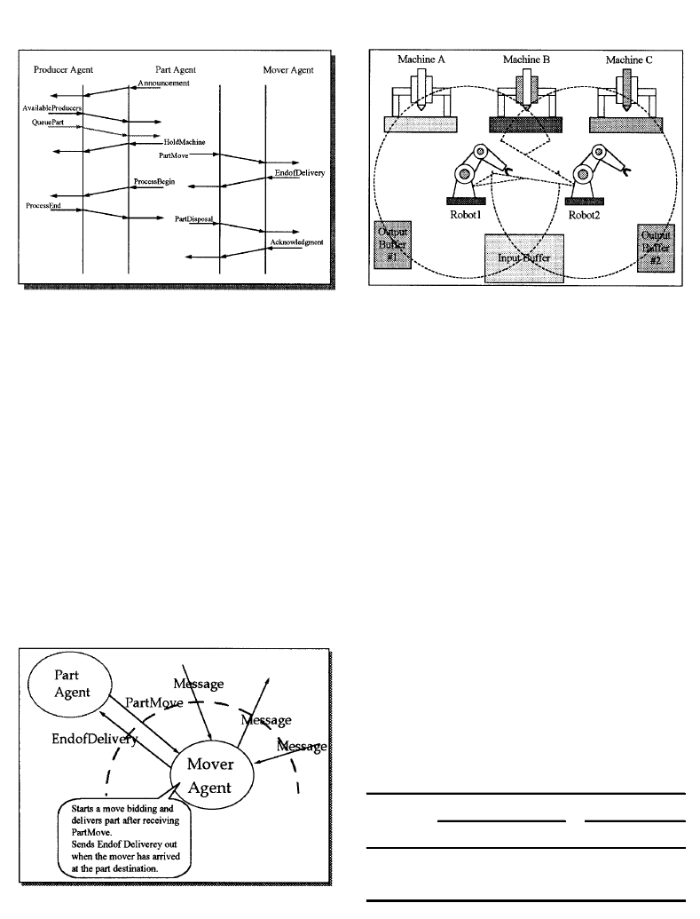
Figure 8 illustrates a partial timing diagram for
producer agent, part agent and mover agent. Some
messages in Figure 8 were not seen in Figure 6, because
they appear at levels below block A0. Note that message
passing is not limited to di erent agent types; it can
also happen between agents of the same type (e.g. for
dispatching vehicles in an AGVS). This has not been
addressed in this ® gure.
In fact, the timing diagram is an important
reference for a programmable logic controller (PLC)
program designer. A set of arrows explicitly present
the passing route. By referring to the timing diagram,
D.-C. Gong and Y.-W. Hsieh
12
Table 2. Summary of activity blocks, objects and information.
Activity Name
Object agent
Information
A1: Task announcement
Part agent
Database agent
A11: Create part list
Part agent
Production orders (or comments) and part information list
A12: Process announcement
Part agent
Available machine list
A13: Delete part list
Part agent
Deleted part information
A14: Update part record
Database agent
Updated part historical data
A2: Machines bidding
Part agent
Producer agent
A21: Check machine status
Producer agent
Machine current status
A22: List available machines
Part agent
Machine capacity and capability
A23: Select machine
Producer agent
Bidding result
A3: Mover bidding and delivery
Part agent
Mover agent
A31: Check mover status
Mover agent
Mover current status
A32: List available movers
Part agent
Mover capacity and capabilities
A33: Select mover
Mover agent
Bidding result
A34: Deliver part to destination
Mover agent
Information on the delivery route
A35: Update record
Part agent
Delivery request completion information
A4: Task processing
Part agent
Producer agent
Database agent
A41: Check machine program
Producer agent
Process data and part processing program
A42: Send program
Database agent
Part processing program
A43: Process task
Producer agent
Condition or data from processing (e.g. tooling, temperature)
A44: Update part list
Part agent
Updated part production information
A5: Mover bidding and disposal
Part agent
Mover agent
A51: Check mover status
Mover agent
Mover current status
A52: List available movers
Part agent
Mover capacity and capability
A53: Select mover
Mover agent
Bidding result
A54: Deliver part out of the system
Mover agent
Information on mover way to disposal
A6: Monitoring
Monitor agent
Resource status and utilization, production progress, and
Database agent
other production related sensory data
Downloaded by [Politechnika Warszawska] at 10:28 18 October 2014
the designer can understand the interaction sequence
between objects, and then write the control program.
In reality, many messages can relate to one object. It
is impossible to depict the entire production in one
timing diagram. Instead, the timing diagram is always
created from each object’s view. In this way, an object
only considers sending messages or reacting to receipt
of a message. The object need not have any knowledge
of the entire system interactions. For example, a part
does not know the delivery procedure being executed
by a vehicle. Once the vehicle arrives at the part
destination, a message of EndofDelivery is released. A
schematic of objects and their message passing in this
example is illustrated in Figure 9.
5. Illustration
To demonstrate the SFCIS design idea and to help
in the understanding of the proposed development
procedure, a simple example is presented in this section.
5.1. System description
A distributed control manufacturing cell is
assumed to process three part types. One distinct
operation is required by each part type. Machine,
robot, input bu er and output bu er are the other
four major components considered in this cell. Their
quantities and the cell con® guration are displayed in
Figure 10.
Machines A, B, and C have di erent capabilities.
Machine A is able to process type 1 and type 3 parts,
machine B can process all three part types, but
machine C cannot process the ® rst part type. The
dotted circles in Figure 10 indicate the workspaces of
two robots, respectively. Both robots share the same
input bu er, but have their own output bu ers. Table 3
lists the capabilities of the various machines and
robots.
Because this cell features distributed control, an
arriving part is stored in the input bu er and waits for
a bidding process to determine the machine to which it
should be sent. Once machine B is selected, an
additional bidding process between robot 1 and
Conceptual design of a shop ¯ oor control information system
13
Figure 8. An example of the message passing timing diagram.
Figure 9. A schematic of object agents and message passing.
Figure 10. A manufacturing cell con® guration.
Table 3. Capabilities of the machines and robots.
Part type
Mover
Type 1
Type 2 Type 3 Robot 1
Robot 2
Machine A
Ö
Ö
Ö
Machine B
Ö
Ö
Ö
Ö
Ö
Machine C
Ö
Ö
Ö
Downloaded by [Politechnika Warszawska] at 10:28 18 October 2014

robot 2 is held. After this operation, the part is moved
via a robot to the output bu er and removed from the
cell.
5.2. System information ¯ ow
In analysing the information ¯ ow, we apply the
proposed development procedure to consider control
functions, to construct an IDEF
0
model, and to obtain
the required data or information for the ® ve objective
agents as listed in Table 4. When a part arrives at the
cell, its agent generates identi® cation data, type data,
status data, process data, and priority data. Priority
indicates, for example, urgency. It may be ® xed and
consistent with the part production due date. It may
also be dynamically adjusted according to the current
system status, especially the machine and bu er status,
to obtain better system performance. The communica-
tion between a part agent and each producer agent
starts after an operation announcement is released (as
given at block A12 in Figure 7). Based on a speci® c
policy, a bidding process is initiated and ends by
sending a message of the result from the producer
agent who wins the bid to the part agent.
Once robot selection is required, a PartMove
message is transmitted to the robots. A robot can
join the bidding only when it is in ready (or idle) or
move
-
® nished (i.e. just completing a move) mode. It
cannot join the bidding if in busy (or moving) or
interlock mode. Refer to block A3 in Figure 6. Note
that the interlock mode is set to avoid collision
between robots.
When a machine is required to perform an opera-
tion, an NC program ® le should be delivered from the
database agent. The status of part and machine is then
updated. After the operation, a robot is responsible for
moving the part to the output bu er and feed back an
Acknowledgement message. Based on this message, the
monitor agent and the database agent start to monitor
and update data such as the processing time,
completion time and cell status.
5.3. Passing messages
Each object agent is normally in `waiting’ mode. It
waits for a new message (or signal) and reacts under
allowable conditions. Possible incoming messages and
conditions of the object agents are illustrated in
Table 5. This table, combined with the IDEF
0
model,
can serve as a basis for creating the message passing
timing chart.
6. Conclusion
Models are created to represent systems. They are
expected to provide a basis for guiding the implemen-
tation of a system. However, there is usually a gap
between design and implementation of manufacturing
systems. The gap exists when the level of abstraction of
D.-C. Gong and Y.-W. Hsieh
14
Table 4. Data contents of the ® ve object agents.
Agents
Data Type
Description
Part agent
PartID
{
0001, 0002, 0003, 0004, 0005
. . .
}
PartType
{
Type1, Type2, Type3
}
Status
{
Queue, Moving, Processing, Part
-
® nished
}
ProcessData
{
NC
-
® le1, NC
-
® le2
,
. . . ,
NC
-
® le
#
}
Priority
{
Low, High
}
Producer agent
MachineID
{
MachineA, MachineB, MachineC
}
ProcessTime
{
5 min, 10 min
,
. . . ,
real number
}
Status
{
Busy, Idle, Maintenance
}
ToolLife
{
5 min, 10 min
,
. . . ,
real number
}
Quality
{
Low, High
}
Mover agent
MoverID
{
Robot1, Robot2
}
Status
{
Moving, move
-
® nished, Ready, Interlock
}
Database agent
NC
-
program
{
NC
-
® le1, NC
-
® le2
,
. . . ,
NC
-
® le
#
}
History
-
data
{
System statistics
}
Monitor agent
Utilization
{
P%
}
Total
-
product
{
Number
}
MachineStatus
{
Busy, Idle, Maintenance, Utilization
}
MoverStatus
{
Moving, move
-
® nished, Ready, Interlock
}
PartStatus
{
Queue, Moving, Processing, Part
-
® nished
}
Downloaded by [Politechnika Warszawska] at 10:28 18 October 2014

a design model is distant from the implementation, or
when not su
cient issues are considered in developing
a model. The shop ¯ oor control information has the
responsibilities of data collection, data management,
and message passing. When developing an SFCIS, one
needs an `engineering’ way to address its related
issuesÐ control, information, and communications.
In this paper, an integrated model of a shop ¯ oor
control information system has been discussed in the
context of system development. Distributed control is
assumed, although the basic approach should be valid
for hierarchical control as well. From the part produc-
tion life cycle, six major activities are determined in
Section 4.1. By applying the O± O concept, ® ve objects
of interest are considered. The control functions are
presented in terms of three control decisions
(induction, routeing and dispatching) on the shop
¯ oor
Furthermore, IDEF has been considered appropriate
for developing functional and information models for
the manufacturing environment. In order to explicitly
express the information ¯ ow, including passing
messages, a modi® ed IDEF
0
block was presented. In
the form of this block, an SFCIS IDEF
0
model was
consequently introduced in Section 4.2. The IDEF
0
model was decomposed to a level at which each block
has one type of object agent. A message passing timing
diagram can therefore be depicted by the messages
between objects. Based on this diagram, designers can
develop the necessary control programs.
Acknowledgement
The authors especially thank Dr Leon McGinnis for
his comments and suggestions.
References
B
AUER
, A., B
ROWNE
, J., B
OWDEN
, R., D
UA GGAN
, J., and L
Y ONS
,
G., 1991,
Shop Floor Control SystemsÐ from Design to Implemen-
tation
(Chapman & Hall, New Y ork).
B
IEMANS
, F. P. M., 1990,
Manufacturing Planning and ControlÐ A
R eference Model
(Elsevier Science Publishers, N.J.)
B
OOCH
, G., 1994,
Object-Oriented Analysis and Design with
Applications
(Benjamin Cummings).
B
OUCHER
, T. O., and J
AFARI
, M. A., 1992, Design of a factory
¯ oor sequence controller from a high level system
speci® cation.
Journal of Manufacturing Systems
, 11, 401± 417.
B
OUCHER
, T. O. M., J
AFA RI
, A., and M
EREDITH
, G. A., 1989,
Petri net control of an automated manufacturing cell.
Computer Ind. Eng
., 17, 459± 463.
B
ROWNE
, J., 1988, Production activity controlÐ a key aspect
of production control.
International Journal of Production
R esearch
, 26, 415± 427.
D
ILTS
, D. M., B
OY D
, N. P., and W
HORMS
, H. H., 1991, The
evolution of control architecture automated manufactur-
ing system.
Journal of Manufacturing Systems
, 10, 79± 93.
D
UFFIE
, N. A., 1990, Synthesis of heterarchical manufacturing
systems.
Computers in Industry
, 14, 167± 174.
D
UFFIE
, N. A. R., C
HITTURI
, R., and M
OU
, J. I., 1988, Fault-
tolerant heterarchical control of heterogeneous manufactur-
ing system entities.
Journal of Manufacturing Systems
, 7, 315± 326.
D
UFFIE
, N. A., and P
IPER
, R. S., 1986, Nonhierarchical control
of manufacturing systems.
Journal of Manufacturing Systems
, 5,
137± 139.
Electronic Industries Association, 1989, Manufacturing
message speci® cationÐ service de® nition and protocol,
EIA Standard
.
G
ONG
, D. C., and K
UO
, Y . L., 1994, Formal speci® cation of a
hybrid shop ¯ oor control architecture using LOTOS.
The
Third International Conference on Automation Technology
, 4,
Taipei, Taiwan, July, pp. 271± 277.
G
ONG
, D. C., and L
IN
, K. F., 1994, Conceptual design of a shop
¯ oor control system from IDEF
0
.
Computer Ind. Eng
., 27,
119± 122.
G
ROOVER
, M. P., 1987,
Automation, Production Systems, and
Computer Integrated Manufacturing
(Prentice-Hall, Englewood
Cli s, NJ).
Conceptual design of a shop ¯ oor control information system
15
Table 5. Receiving messages of object agents.
Agents
Message
Condition
Part agent
AvailableProducers
Machine in working condition
QueuePart
Machine
=
busy
Endof Delivery
Arriging at destination
ProcessEnd
End of operation
Acknowledment
Out of the system
Producer agent
Announcement
Input buffer
/
=
empty
HoldMachine
Machine
=
idle
ProcessBegin
Operation to be started
Mover agent
PartMove
To bid robot
PartDisposal
To bid robot and move to the output bu er
Database agent
StoreFile
SendFile
Monitor agent
ReadData
Downloaded by [Politechnika Warszawska] at 10:28 18 October 2014

H
AN
, M. H., and M
C
G
INNIS
, L. F., 1989, Work¯ ow control in
¯ exible manufacturing: minimization of stockout cost.
International Journal of Production R esearch
, 27, 701± 716.
J
ONES
, A. T., and M
C
L
EAN
, C. R., 1986, A proposed hierarchical
control model for automated manufacturing systems.
Journal
of Manufacturing Systems
, 5, 15± 25.
K
IM
, C., K
IM
, K., and C
HOI
, I., 1993, An object- oriented
information modeling methodology for manufacturing
information systems.
Computer Ind. Eng
., 24, 337± 353.
L
EE
, K. H., and S
EN
, S., 1994, ICOSS: a two- layer object- based
intelligent cell control architecture.
Computer-Integrated
Manufacturing Systems
, 7, 100± 112.
L
IN
, G. Y. J., and S
OLBERG
, J. J., 1992, Integrated shop ¯ oor control
using autonomous agents.
IIE Transactions
, 24(3), 57± 71.
M
ELNY K
, S. A., and C
ARTER
, P. L., 1987,
Production Activity
Control
(Richard D. Irwin, Homewood, IL).
N
GWENY AMA
, O. K., and G
RANT
, D. A., 1994, Enterprise
modeling for CIM information systems architectures: an
object- oriented approach.
Computers Ind. Eng
., 26, 279± 293.
O’G
RADY
, P., and S
ESHADRI
, R., 1992, Operation of X-
cellÐ an intelligent cell control system.
Computer-Inte-
grated Manufacturing Systems
, 5, 21± 30.
P
ANDY A
, K., V
INODRAI
, 1994, Model for production planning
and control decisions at cell level: a case study.
Computer
Integrated Manufacturing Systems
, 7, 75± 92.
R
UMBAUGH
, J., B
LAHA
, M., P
REMERLANI
, W., E
DDY
, F., and
L
ORENSEN
, W., 1991,
Object-Oriented Modeling and Design
(Prentice-Hall International, Englewood Cli s, NJ).
S
HANMUGHAM
, S. G., B
EAUMARIAGE
, T. G., R
OBERTS
, C. A., and
R
OLLIER
, D. A., 1995, Manufacturing communication: a
review of the MMS approach.
Computers Ind. Eng
., 28,
1± 21.
V
EERAMANI
, D., B
HARGAVA
, B., and B
ARASH
, M. M., 1993,
Information system architecture for heterarchical control
of large FMSs.
Computer Integrated Manufacturing Systems
, 6,
76± 92.
V
EERAMANI
, D., 1994, Distributed and dynamic shop-¯ oor
control in intelligent manufacturing systems.
Conference on
Computer Integrated Manufacturing in the Process Industries
, pp.
296± 410.
Y
EP
, C. K., B
OEY
, S. H., and G
OH
, J., 1993, Information ¯ ow
modeling of a ¯ exible cell controller.
Proceedings of the
International Conference on Industrial Electronics, Control, and
Instrumentation
, 1, pp. 575± 580.
D.-C. Gong and Y.-W. Hsieh
16
Downloaded by [Politechnika Warszawska] at 10:28 18 October 2014
Wyszukiwarka
Podobne podstrony:
095119296131788id 8134 Nieznany (2)
Gor±czka o nieznanej etiologii
02 VIC 10 Days Cumulative A D O Nieznany (2)
Abolicja podatkowa id 50334 Nieznany (2)
45 sekundowa prezentacja w 4 ro Nieznany (2)
4 LIDER MENEDZER id 37733 Nieznany (2)
Mechanika Plynow Lab, Sitka Pro Nieznany
katechezy MB id 233498 Nieznany
2012 styczen OPEXid 27724 Nieznany
metro sciaga id 296943 Nieznany
Mazowieckie Studia Humanistyczn Nieznany (11)
cw 16 odpowiedzi do pytan id 1 Nieznany
perf id 354744 Nieznany
DO TEL! 5= Genetyka nadci nieni Nieznany
Opracowanie FINAL miniaturka id Nieznany
3 Podstawy fizyki polprzewodnik Nieznany (2)
interbase id 92028 Nieznany
Mbaku id 289860 Nieznany
więcej podobnych podstron