4B•1
Chapter 4 Part B: Fuel and exhaust systems -
single-point fuel injection models
Contents
Accelerator cable - removal, refitting and adjustment 4
Accelerator pedal - removal and refitting 5
Air cleaner air temperature control system - general
information and component renewal 3
Air cleaner assembly and intake ducts - removal and refitting 2
Air cleaner filter element renewal See Chapter 1
Bosch Monopoint system components - removal and refitting . . . . 14
Exhaust manifold - removal and refitting 17
Exhaust system - general information, removal and refitting 18
Exhaust system check See Chapter 1
Fuel filter - renewal See Chapter 1
Fuel gauge sender unit - removal and refitting 10
Degrees of difficulty
Fuel injection system - depressurisation 8
Fuel injection system - testing and adjustment 13
Fuel injection systems - general information 7
Fuel pump - removal and refitting 9
Fuel tank - removal and refitting 11
General fuel system checks See Chapter 1
General information and precautions 1
Idle speed and mixture adjustment See Chapter 1
Inlet manifold - removal and refitting 16
Magneti Marelli system components - removal and refitting 15
Throttle body - removal and refitting 12
Unleaded petrol - general information and usage 6
Easy, suitable for
novice with little
experience
Fairly easy, suitable
for beginner with
some experience
Fairly difficult, suitable
for competent DIY
mechanic
Difficult, suitable for
experienced DIY
mechanic
Very difficult,
suitable for expert DIY
or professional
Specifications
System type
1124 cc (H1A engine) models Bosch Monopoint A2.2
1360 cc (KDY engine) models Bosch Monopoint A2.2
1360 cc (KDX engine) models Bosch Monopoint MA3.0
Early 1580 cc (B4A engine) models Magneti Marelli G5.S2
Later 1580 cc (B4A engine) models Magneti Marelli G6.12
1580 cc (BDY engine) models Magneti Marelli G6.10
Note: Refer to the relevant part of Chapter 2 for further information on engine code identification
Fuel system data
Fuel pump type Electric, immersed in tank
Fuel pump regulated constant pressure:
Bosch system 1.0 bar
Magneti Marelli system 0.8 ± 0.1 bar
Specified idle speed (not adjustable) 850 ± 50 rpm (controlled by ECU)
Idle mixture CO content:
Bosch system (not adjustable) Less than 1.0 % (controlled by ECU)
Magneti Marelli system*:
1580 cc (B4A engine) models 1.0 to 2.0 %
1580 cc (BDY engine) models Less than 1.0 % (controlled by ECU)
*On the Magneti Marelli system, idle mixture adjustment is possible, but only using special electronic equipment - see text
Recommended fuel
Minimum octane rating:
1580 cc (B4A engine) models 95 RON unleaded (UK unleaded premium) or
97 RON leaded (UK "4-star")
1580 cc (BDY engine) models, and all 1124 cc and 1360 cc models . 95 RON unleaded (UK unleaded premium).
Leaded fuel must not be used
4B•2 Fuel and exhaust systems - single-point fuel injection models
Torque w r e n c h settings Nm lbf ft
Inlet manifold nuts:
1124 cc and 1360 cc models 8 6
1580 cc models 22 16
Exhaust manifold nuts:
1124 cc and 1360 cc models 16
12
1580 cc models 22 16
Exhaust system fasteners:
1124 cc and 1360 cc models:
Front pipe-to-manifold nuts 30 22
Front pipe mounting bolt 35 26
Front pipe-to-intermediate pipe nuts 10 7
Clamping ring nuts 20 15
1580 cc models:
Front pipe-to-manifold nuts 10 7
Clamping ring nuts 20 15
The fuel system consists of a fuel tank
(which is mounted under the rear of the car,
with an electric fuel pump immersed in it), a
fuel filter, fuel feed and return lines, and the
throttle body assembly (which incorporates
the single fuel injector and the fuel pressure
regulator). In addition, there is an Electronic
Control Unit (ECU) and various sensors,
electrical components and related wiring. The
air cleaner contains a disposable paper filter
element, and incorporates a flap valve air
temperature control system. This allows cold
air from the outside of the car and warm air
from around the exhaust manifold to enter the
air cleaner in the correct proportions.
Refer to Section 7 for further information on
the operation of each fuel injection system,
and to Section 18 for information on the
exhaust system.
Throughout this Section, it is occasionally
necessary to identify vehicles by their engine
codes rather than by engine capacity. Refer to
the relevant Part of Chapter 2 for further
information on engine code identification.
Warning: Many of the procedures
in this Chapter require the
removal of fuel lines and
connections, which may result in
some fuel spillage. Before carrying out any
operation on the fuel system, refer to the
precautions given in "Safety first!" at the
beginning of this manual, and follow them
implicitly. Petrol is a highly-dangerous and
volatile liquid, and the precautions
necessary when handling it cannot be
overstressed.
Note: Residual pressure will remain in the
fuel lines long after the vehicle was last used.
When disconnecting any fuel line, first
depressurise the fuel system as described in
Section 8.
1124 cc and 1360 cc models
1 Refer to Chapter 4A, Section 2, substituting
"throttle body" for all references to the
carburettor.
1580 cc models
Removal
2 Slacken the retaining clip, and disconnect
the air cleaner housing-to-throttle body duct
from the front of the air cleaner housing.
3 Slacken the retaining clip, and disconnect
the air cleaner air temperature control valve
assembly from the end of the air cleaner
housing.
4 Free the air cleaner housing retaining strap
from its retaining clip, then lift the air cleaner
housing away from its mounting bracket. If
necessary, the mounting bracket can then be
unbolted and removed from the engine
compartment (see illustrations).
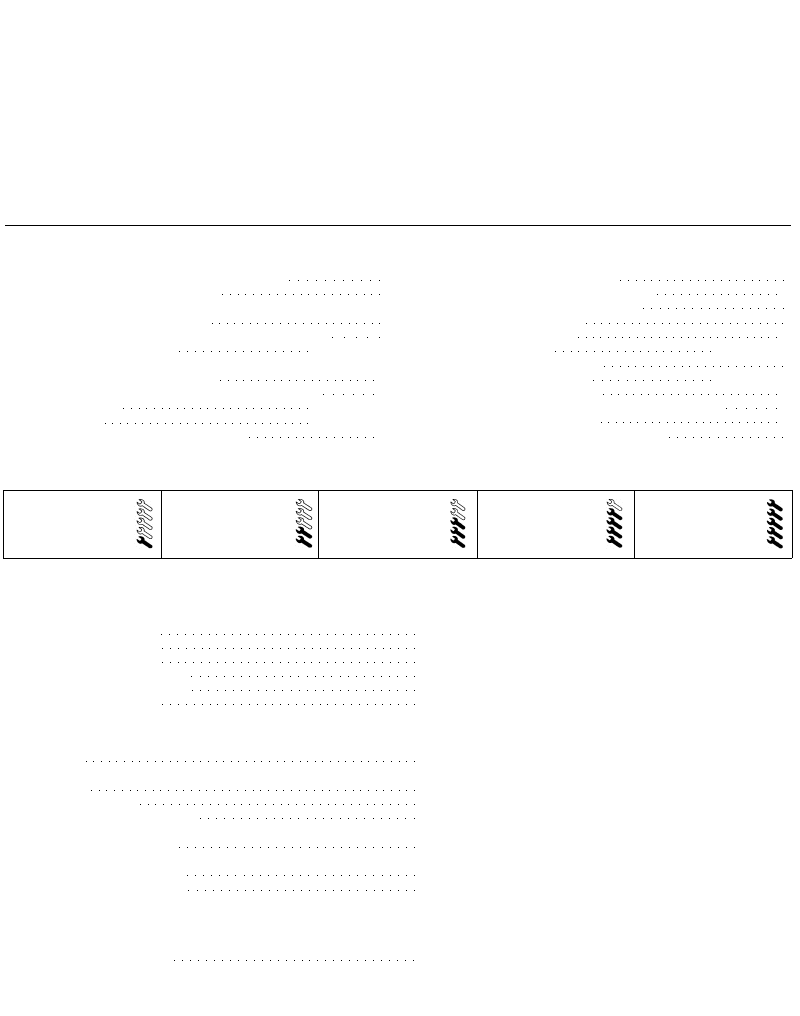
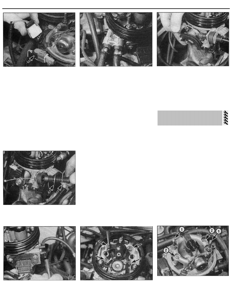
5 To remove the intake duct, first disconnect
the vacuum hose from the air temperature
control valve diaphragm. If not already done,
slacken the retaining clip securing the control
valve to the air cleaner housing. Undo the
nut(s) securing the front of the duct to the
vehicle body, then release the fastener
securing the rear of the duct in position.
Disconnect the hot-air intake hose from the
manifold shroud, and remove the duct and
hose assembly from the engine compartment
(see illustration).
2.4a On 1580 cc models, release the
rubber retaining strap . . .
2.4b . . . and lift the air cleaner housing out
of the engine compartment
2.4c Air cleaner mounting bracket
retaining bolts (arrowed) -1580 cc models
2.5 Removing the intake duct and hose
assembly -1580 cc models
1 General information and
precautions
2 Air cleaner assembly and intake
ducts - removal and refitting
Fuel and exhaust systems - single-point fuel injection models 4B•3
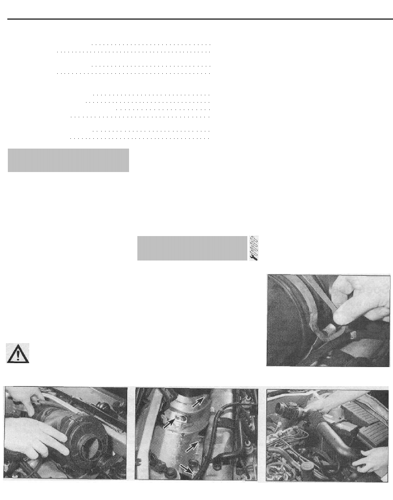
6 To remove the air cleaner housing-to-
throttle body duct, disconnect the breather
hose from the side of the duct, then
disconnect the vacuum hoses from the air
temperature control system vacuum valve,
noting their correct fitted positions. Slacken
the retaining clip securing the duct to the air
cleaner housing, then slacken and remove the
two nuts and washers securing the duct to the
throttle body. Remove the duct from engine
compartment. On early models, it will be
necessary to disconnect the auxiliary air valve
hose from the duct, and to recover the rubber
sealing ring from the top of the throttle body
(see illustrations).
Refitting
7 Refitting is a reversal of the removal
procedure, ensuring that all hoses are
properly reconnected, and that all ducts are
correctly seated and securely held by their
retaining clips.
1124 cc and 1360 cc models
1 Refer to Chapter 4A, Section 3, substituting
"throttle body" for all references to the
carburettor.
1580 cc models
General information
2 Refer to Chapter 4A, Section 3, substituting
"throttle body" for all references to the
carburettor.
Vacuum switch - renewal
3 Remove the air cleaner-to-throttle body
duct as described in paragraph 6 of Section 2.
4 Bend up the tangs on the switch retaining
clip, then remove the clip and withdraw the
switch from inside the duct.
5 On refitting, ensure the switch and duct
mating surfaces are clean and dry, and
position the switch on the inside of the duct.
Refit the retaining clip, then press the switch
firmly against the duct, securing it in position
by bending down the retaining clip tangs.
6 Refit the duct as described in Section 2.
Air temperature control valve -
renewal
7 Disconnect the vacuum pipe from the air
temperature control valve, then slacken the
retaining clips securing the valve to the air
cleaner housing, hot-air intake hose, and the
intake duct.
8 Disconnect the intake duct and hose from
the control valve, then free the valve from the
air cleaner assembly and remove it from the
vehicle.
9 Refitting is the reverse of the removal
2.6a Undo the two retaining nuts . . .
procedure, noting that the air temperature
control valve assembly can only be renewed
as a complete unit.
1 Refer to Chapter 4A, Section 7, substituting
"throttle body" for all references to the
carburettor. On automatic transmission
models, once the accelerator cable is
correctly adjusted, check the kickdown cable
adjustment as described in Chapter 7B.
Refer to Chapter 4A, Section 8.
Note: The information given in this Chapter is
correct at the time of writing. If updated
information is thought to be required, check
with a Citroen dealer. If travelling abroad,
consult one of the motoring organisations (or a
similar authority) for advice on the fuel
available.
1 The fuel recommended by Citroen is given
in the Specifications Section of this Chapter,
followed by the equivalent petrol currently on
sale in the UK.
2 All Citroen ZX single-point injection models
are designed to run on fuel with a minimum
octane rating of 95 (RON). All 1124 cc and
1360 cc models are equipped with catalytic
converters, and therefore must be run on
unleaded fuel only. Under no circumstances
should leaded (UK "4-star") fuel be used, as
this may damage the catalytic converter. This
also applies to later 1580 cc models with a
catalytic converter. Early 1580 cc models
without a catalytic converter can, however, be
run on leaded fuel without modification or risk
of damage.
3 Super unleaded petrol (98 octane) can also
be used in all models if wished, though there
is no advantage in doing so.
2.6b . . . then detach the duct from the
throttle body, and recover the sealing ring
Bosch Monopoint A2.2 system -
1124 cc and early 1360 cc models
1 The Bosch Monopoint A2.2 fuel injection
system is fitted to all 1124 cc fuel-injected
models, and to early fuel-injected 1360 cc
(KDY engine) models. The system
incorporates a closed-loop catalytic
converter and an evaporative emission
control system, and complies with the latest
emission control standards. The system
operates as follows.
2 The fuel pump, immersed in the fuel tank,
pumps fuel from the fuel tank to the fuel
injector, via a filter mounted underneath the
rear of the vehicle. Fuel supply pressure is
controlled by the pressure regulator in the
throttle body assembly. The regulator
operates by allowing excess fuel to return to
the tank.
3 The electrical control system consists of the
ECU, along with the following sensors.
(a) Throttle potentiometer - informs the ECU
of the throttle position, and the rate of
throttle opening or closing.
(b) Coolant temperature sensor - informs the
ECU of engine temperature.
(c) Intake air temperature sensor - informs
the ECU of the temperature of the air
passing through the throttle body.
(d) Lambda sensor - informs the ECU of the
oxygen content of the exhaust gases
(explained in greater detail in Part D of
this Chapter).
(e) Microswitch (built into idle speed stepper
motor) - informs the ECU when the
throttle valve is closed (ie when the
accelerator pedal is released).
(f) Ignition HT coil - ECU monitors the coil
low tension (LT) circuit to determine the
engine speed.
4 All the above information is analysed by the
ECU and, based on this, the ECU determines
the appropriate fuelling requirements for the
engine. The ECU controls the fuel injector by
varying its pulse width - the length of time the
injector is held open - to provide a richer or
3 Air cleaner air temperature
control system -
general information and
component renewal
7 Fuel injection systems - general
information
5 Accelerator pedal -
removal and refitting
6 Unleaded petrol -
general information and usage
4 Accelerator cable - removal,
refitting and adjustment

4B•4 Fuel and exhaust systems - single-point fuel injection models
weaker mixture, as appropriate. The mixture is
constantly varied by the ECU, to provide the
best setting for cranking, starting (with either a
hot or cold engine), warm-up, idle, cruising,
and acceleration.
5 The ECU also has full control over the
engine idle speed, via a stepper motor which
is fitted to the throttle body. The motor
pushrod rests against a cam on the throttle
valve spindle. When the throttle valve is
closed (accelerator pedal released), the ECU
uses the motor to vary the opening of the
throttle valve and so control the idle speed.
6 The ECU also controls the exhaust and
evaporative emission control systems, which
are described in detail in Part D of this
Chapter.
7 If there is an abnormality in any of the
readings obtained from either the coolant
temperature sensor, the intake air
temperature sensor or the lambda sensor, the
ECU enters its back-up mode. In this event,
the ECU ignores the abnormal sensor signal,
and assumes a pre-programmed value which
will allow the engine to continue running
(albeit at reduced efficiency). If the ECU enters
this back-up mode, the warning light on the
instrument panel will come on, and the
relevant fault code will be stored in the ECU
memory.
8 If the warning light comes on, the vehicle
should be taken to a Citroen dealer at the
earliest opportunity. A complete test of the
engine management system can then be
carried out, using a special electronic
diagnostic test unit which is simply plugged
into the system's diagnostic connector.
Bosch Monopoint MA3.0 system -
later 1360 cc models
9 The Bosch Monopoint MA3.0 engine
management (fuel injection/ignition) system is
fitted to all later 1360 cc models with the
KDX engine. The system differs from the
earlier A2.2 system in that it is an engine
management system, controlling both the fuel
injection system and ignition system, rather
than purely a fuel injection system. Refer to
Chapter 5 for information on the ignition side
of the system.
10 The fuel injection side of the system is
very similar to the A2.2 system described
above, the only difference being that a couple
of additional sensors are incorporated into the
system. A crankshaft sensor is fitted to the
engine, to inform the ECU of engine speed
and crankshaft position, and a vehicle speed
sensor is fitted to the gearbox, to inform the
ECU of the road speed.
11 The crankshaft sensor is needed since the
ECU also controls the ignition side of the
system, and cannot use the ignition low
tension (LT) circuit to calculate engine speed.
The sensor works in conjunction with a
reluctor ring fixed to the rear of the flywheel.
The reluctor ring originally has a total of sixty
teeth, which are equally-spaced at intervals of
6°. Of these sixty teeth, two adjacent teeth are
removed, to leave a gap of 18°. The ECU uses
this gap to establish where TDC is, and
calculates engine speed from the frequency of
teeth passing the crankshaft sensor.
Magneti Marelli system - 1580 cc
models
12 On 1580 cc models, a Magneti Marelli
engine management (fuel injection/ignition)
system is fitted. There are three versions of
the system, all of which differ slightly, but
operate on the same principle. The
differences are as follows.
13 Early models with the B4A (XU5M 2K)
engine are fitted with the G5.S2 system. This
system differs from later models in thatlt uses
an auxiliary air valve to control the engine idle
speed.
14 Later models with the B4A (XU5M 2K or
3K) engine are fitted with the G6.12 system.
On this system, a stepper motor is fitted to the
throttle body assembly to control the engine
idle speed.
15 Later models with the BDY engine are
fitted with the G6.10 system. This system is a
development of the G6.12 system,
incorporating a catalytic converter and an
evaporative emission control system.
16 The fuel injection side of the system
operates as described in the following
paragraphs. Refer to Chapter 5 for information
on the ignition side of the system.
17 The fuel pump, immersed in the fuel tank,
pumps fuel from the fuel tank to the fuel
injector, via a filter. Fuel supply pressure is
controlled by the pressure regulator in the
throttle body assembly. The regulator
operates by allowing excess fuel to return to
the tank. To reduce emissions and to improve
driveability when the engine is cold, engine
coolant is passed through the manifold and
around the throttle body assembly.
18 The electrical control system consists of
the ECU, along with the following sensors.
(a) Manifold absolute pressure (MAP) sensor
- informs the ECU of the load on the
engine (expressed in terms of inlet
manifold vacuum).
(b) Crankshaft sensor - informs the ECU of
crankshaft position and engine speed.
(c) Throttle potentiometer - informs the ECU
of the throttle position, and the rate of
throttle opening/closing.
(d) Coolant temperature sensor - informs the
ECU of engine temperature.
(e) Fuel/air mixture temperature sensor -
informs the ECU of the temperature of the
fuel/air mixture charge entering the
cylinders.
(f) Lambda (oxygen) sensor - informs the
ECU of the oxygen content of the exhaust
gases (explained in greater detail in Part D
of this Chapter).
19 In addition, the ECU senses battery
voltage (adjusting the injector pulse width to
suit, and using the stepper motor to increase
the idle speed and, therefore, the alternator
output if the voltage is too low). Short-circuit
protection and diagnostic capabilities are
incorporated into the ECU, and it can both
receive and transmit information via the
engine management circuit diagnostic
connector, thus permitting engine diagnosis
and tuning by special diagnostic equipment.
20 All the above signals are compared by the
ECU, using digital techniques, with set values
pre-programmed (mapped) into its memory.
Based on this information, the ECU selects
the response appropriate to those values, and
controls the ignition HT coil (see Chapter 5),
and the fuel injector (varying its pulse width -
the length of time the injector is held open - to
provide a richer or weaker mixture, as
appropriate). The mixture, idle speed and
ignition timing are constantly varied by the
ECU, to provide the best settings for cranking,
starting (with either a hot or cold engine),
warm-up, idle, cruising, and acceleration.
21 On the G5.S2 system, the ECU controls
the idle speed via an auxiliary air valve. The air
valve is connected to the air intake duct and
to the throttle body, downstream of the
throttle valve. When the throttle valve is
closed, the ECU controls the opening of the
valve, which in turn regulates the amount of
air entering the manifold, and so controls the
idle speed.
22 On the G6.12 and G6.10 systems, the
ECU regulates the engine idle speed via a
stepper motor which is fitted to the throttle
body. The motor has a pushrod controlling the
opening of an air passage which bypasses the
throttle valve. When the throttle valve is
closed, the ECU controls the movement of the
motor pushrod, which regulates the amount of
air which flows through the throttle body
passage, and so controls the idle speed. The
bypass passage is also used as an additional
air supply during cold starting.
23 On the G6.10 system, the ECU also
controls the exhaust and evaporative
emission control systems, which are
described in detail in Part D of this Chapter.
24 If there is an abnormality in any of the
readings obtained from any of engine
management circuit sensors, the ECU enters
its back-up mode. In this event, the ECU
ignores the abnormal sensor signal, and
assumes a pre-programmed value which will
allow the engine to continue running (albeit at
reduced efficiency). On entering this back-up
mode, the engine management warning light
in the instrument panel will come on,
informing the driver of the fault, and the
relevant fault code will be stored in the ECU
memory.
25 If the warning light comes on, the vehicle
should be taken to a Citroen dealer at the
earliest opportunity. A complete test of the
engine management system can then be
carried out, using a special electronic
diagnostic test unit which is simply plugged
into the system's diagnostic connector.
Fuel and exhaust systems - single-point fuel injection models 4B•5
Note: Refer to the warning note in Section 1
before proceeding.
Warning: The following
procedure will merely relieve the
pressure in the fuel system -
remember that fuel will still be
present in the system components, and
take precautions accordingly before
disconnecting any of them.
1 The fuel system referred to in this Section is
defined as the tank-mounted fuel pump, the
fuel filter, the fuel injector and the pressure
regulator in the injector housing, and the
metal pipes and flexible hoses of the fuel lines
between these components. All these contain
fuel which will be under pressure while the
engine is running, and/or while the ignition is
switched on. The pressure will remain for
some time after the ignition has been
switched off, and it must be relieved in a
controlled fashion when any of these
components are disturbed for servicing work.
2 Disconnect the battery negative terminal.
3 Place a suitable container beneath the
connection or union to be disconnected, and
have a large rag ready to soak up any
escaping fuel not being caught by the
container.
4 Slowly loosen the connection or union nut
to avoid a sudden release of pressure, and
position the rag around the connection, to
catch any fuel spray which may be expelled.
Once the pressure is released, disconnect the
fuel line. Plug the pipe ends, to minimise fuel
loss and prevent the entry of dirt into the fuel
system.
Note: Refer to the warning note in Section 1
before proceeding.
Removal
1 Disconnect the battery negative lead.
2 For access to the fuel pump, tilt or remove
the rear seats as described in Chapter 11.
3 Using a screwdriver, carefully prise the
plastic access cover from the floor to expose
the fuel pump. The pump is located under the
right-hand cover.
4 Disconnect the wiring connector from the
fuel pump, and tape the connector to the
vehicle body, to prevent it disappearing
behind the tank.
5 Mark the hoses for identification purposes,
then slacken the feed and return hose
retaining clips. Where the crimped-type
Citroen hose clips are fitted, cut the clips and
discard them; use standard worm-drive hose
clips on refitting. Disconnect both hoses from
the top of the pump, and plug the hose ends.
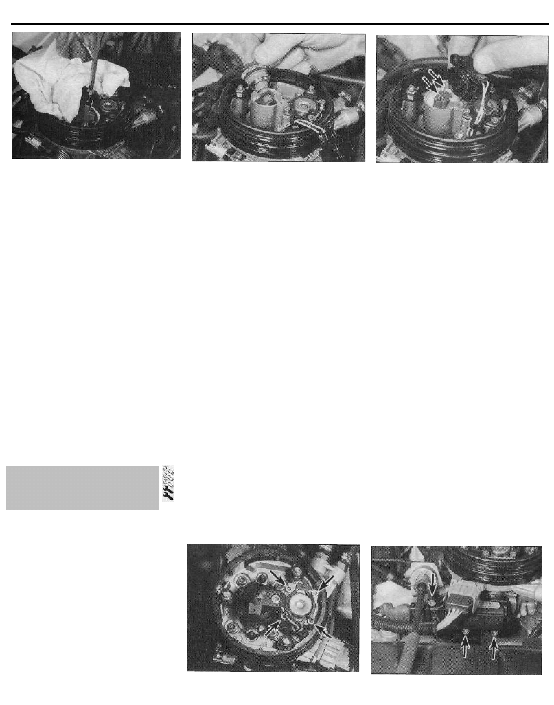
6 Noting the alignment marks on the tank,
pump cover and the locking ring, unscrew the
ring and remove it from the tank. This is best
accomplished by using a screwdriver on the
raised ribs of the locking ring. Carefully tap
the screwdriver to turn the ring anti-clockwise
until it can be unscrewed by hand.
7 Displace the pump .cover, then reach into
the tank and unclip the pump from the tank
base. Lift the fuel pump assembly out of the
fuel tank, taking great care not to damage the
filter, or to spill fuel onto the interior of the
vehicle. Recover the rubber sealing ring and
discard it - a new one must be used on
refitting.
8 Note that the fuel pump is only available as
a complete assembly - no components are
available separately.
Refitting
9 Ensure the fuel pump pick-up filter is clean
and free of debris. Fit the new sealing ring to
the top of the fuel tank.
10 Carefully manoeuvre the pump assembly
into the fuel tank, and clip it into position in
the base of the tank.
11 Align the mark on the fuel pump cover
with the centre of the three alignment marks
on the fuel tank, then refit the locking ring.
Securely tighten the locking ring, then check
that the locking ring, pump cover and tank
marks are all correctly aligned.
12 Reconnect the feed and return hoses to
the top of the fuel pump, using the marks
made on removal to ensure that they are
correctly reconnected, and securely tighten
their retaining clips.
13 Reconnect the pump wiring connector.
14 Reconnect the battery negative terminal,
and start the engine. Check the fuel pump
feed and return hoses unions for signs of
leakage.
15 If all is well, refit the plastic access cover.
Tilt or refit the rear seat as described in
Chapter 11 (as applicable).
10 Fuel gauge sender unit -
removal and refitting
Refer to Chapter 4A, Section 5, noting that
there are no fuel pipe connections to the
sender unit.
11 Fuel tank -
removal and refitting
Refer to Chapter 4A, Section 6, noting that
it will be necessary to depressurise the fuel
system as the feed and return hoses are
disconnected (see Section 8). It will also be
necessary to disconnect the wiring connector
from the fuel pump before lowering the tank
out of position.
12 Throttle body -
removal and refitting
Note: Refer to the warning note in Section 1
before proceeding.
Removal
1 Disconnect the battery negative terminal.
2 On 1124 cc and 1360 cc models, remove
the air cleaner housing-to-throttle body duct,
using the information given in Section 2.
3 On 1580 cc models, relieve any pressure in
the cooling system by unscrewing the filler
cap. Undo the two nuts securing the intake
duct to the throttle body, and position the
duct clear of the body along with its rubber
sealing ring. Working quickly to minimise
coolant loss, disconnect the two coolant
hoses from the rear of the throttle body
assembly, and plug the hose ends with a
suitable bolt or screw (see illustration).
4 Depress the retaining clips and disconnect
the wiring connectors from the throttle
12.3 Throttle body coolant hoses
(arrowed) -1580 cc models
12.4a On 1124 cc and 1360 cc models,
disconnect the wiring connectors from the 12.4b . . . the idle control stepper motor
throttle potentiometer . . . and the injector wiring loom (arrowed)
8 Fuel injection system -
depressurisation
9 Fuel pump -
removal and refitting
4B•6 Fuel and exhaust systems - single-point fuel injection models
12.4c Disconnecting the throttle
potentiometer wiring connector - 1580 cc
models (injector wiring connector arrowed)
potentiometer, the idle control stepper motor
(where fitted), and the injector wiring loom
connector which is situated on the side of the
throttle body (see illustrations).
5 Bearing in mind the information given in
Section 8 about depressurising the fuel
system, release the retaining clips and
disconnect the fuel feed and return hoses
from the throttle body assembly. If the original
crimped-type Citroen clips are still fitted, cut
the clips and discard them; use standard
worm-drive hose clips on refitting (see
illustration).
6 Disconnect the accelerator inner cable from
the throttle cam, then withdraw the outer
12.6b . . . then free the outer cable from its
bracket, and recover the flat washer and
spring clip (arrowed) - 1360 cc model
shown
12.5 Throttle body fuel feed and return
hose unions (1360 cc model shown)
cable from the mounting bracket, along with
its flat washer and spring clip (see
illustrations).
7 Disconnect the distributor vacuum hose,
idle control auxiliary air valve and/or purge
valve hose from the throttle body (as
applicable) (see illustration).
8 Slacken and remove the bolts securing the
throttle body assembly to the inlet manifold,
then remove the assembly along with its
gasket and/or insulating spacer (see
illustrations).
9 If necessary, with the throttle body
removed, undo the retaining screws and
separate the upper and lower sections, noting
the gasket which is fitted between the two.
Refitting
10 Refitting is a reverse of the removal
procedure, bearing in mind the following
points:
(a) Where applicable, ensure the mating
surfaces of the upper and lower throttle
body sections are clean and dry. Fit a new
gasket and reassemble the two sections,
tightening the retaining screws securely.
(b) Ensure the mating surfaces of the
manifold and throttle body are clean and
dry, then fit a new gasket. Securely
tighten the throttle body retaining bolts.
(c) Ensure all hoses are correctly
reconnected and, where necessary, that
their retaining clips are securely
tightened.
12.6a Disconnect the accelerator inner
cable from the throttle cam . . .
(d) On completion, adjust the accelerator
cable using the information given in
Section 4.
(e) On 1580 cc models, check and, if
necessary, top-up the cooling system as
described in Chapter 1.
Testing
1 If a fault appears in the fuel injection
system, first ensure that all the system wiring
connectors are securely connected and free
of corrosion. Ensure that the fault is not due to
poor maintenance; ie, check that the air
cleaner filter element is clean, the spark plugs
are in good condition and correctly gapped,
the valve clearances are correctly adjusted,
the cylinder compression pressures are
correct, the ignition timing is correct, and that
the engine breather hoses are clear and
undamaged, referring to Chapters 1, 2 and 5
for further information.
2 If these checks fail to reveal the cause of
the problem, the vehicle should be taken to a
suitably-equipped Citroen dealer for testing. A
wiring block connector is incorporated in the
engine management circuit, into which a
special electronic diagnostic tester can be
plugged. The connector is located inside
either the engine compartment junction box or
12.7 Disconnecting the purge valve hose
from the throttle body - 1360 cc model
12.8a Throttle body retaining bolts
(arrowed) -1360 cc model
12 8b Throttle bodv retaining bolts/
studs (1) and upper body retaining
screws (2) - 1580 cc model
13 Fuel injection system -
testing and adjustment
Fuel and exhaust systems - single-point fuel injection models 4B•7
14.3a Undo the injector cap retaining
screw, noting the use of a rag to catch any
fuel spray . . .
the ECU plastic box. The tester will locate the
fault quickly and simply, alleviating the need
to test all the system components individually,
which is a time-consuming operation that also
carries a risk of damaging the ECU.
Adjustment
3 Experienced home mechanics with a
considerable amount of skill and equipment
(including a tachometer and an accurately
calibrated exhaust gas analyser) may be able to
check the exhaust CO level and the idle speed.
However, if these are found to be in need of
adjustment, the car must be taken to a suitably-
equipped Citroen dealer for further testing.
4 On the Bosch Monopoint system, no
adjustment is possible. Should the idle speed
or exhaust gas CO level be incorrect, then a
fault must be present in the fuel injection
system.
5 On the Magneti Marelli system, it is
possible to adjust the mixture setting (exhaust
gas CO level) and ignition timing. However,
adjustments can be made only by re-
programming the ECU, using special
diagnostic equipment connected to the
system via the diagnostic connector.
14 Bosch Monopoint system
components -
removal and refitting
Note: On later 1360 cc models with the MA3.0
system, the throttle body is effectively a
sealed unit, with no components available
separately. This means that, if any of the
throttle body components (including the idle
control stepper motor) become faulty, the
complete assembly must be renewed.
Fuel injector
Note: Refer to the warning note in Section 1
before proceeding. If a faulty injector is
suspected, before condemning the injector, it
is worth trying the effect of one of the
proprietary injector-cleaning treatments.
On later 1360 cc models with the MA3.0
system, at the time of writing, neither the fuel
injector or its seals are available separately. If
the injector is faulty, the complete throttle
body assembly must be renewed. Refer to
14.3b . . . then lift off the cap and withdraw
the injector
your Citroen dealer for the latest information.
Although the unit can be dismantled for
cleaning, if required, it should not be
disturbed unless absolutely necessary.
1 Disconnect the battery negative terminal.
2 Remove the air cleaner-to-throttle body
duct, using the information given in Section 2.
3 Undo the injector cap retaining screw, then
lift off the cap and withdraw the injector from
the housing, noting the sealing ring and O-
ring. As the cap screw is slackened and the
injector is withdrawn, place a clean rag over
the injector, to catch any fuel spray which may
be released (see illustrations).
4 Refitting is a reversal of the removal
procedure, ensuring that the injector sealing
ring(s) and injector cap O-ring are in good
condition. When refitting the injector cap,
ensure that the injector pins are correctly
aligned with the cap terminals - the terminals
are marked "+" and "-" for identification (see
illustration).
Fuel pressure regulator
Note: Refer to the warning note in Section 1
before proceeding. At the time of writing, the
fuel pressure regulator assembly was not
available separately from the throttle body
assembly. Refer to a Citroen dealer for the
latest information. Although the unit can be
dismantled for cleaning, if required, it should
not be disturbed unless absolutely necessary.
5 Disconnect the battery negative terminal.
6 Remove the air cleaner-to-throttle body
14.4 On refitting, ensure that the cap
terminals are correctly aligned with the
injector pins (arrowed)
duct, using the information given in Section 2.
7 Using a marker pen, make alignment marks
between the regulator cover and throttle
body, then slacken and remove the cover
retaining screws (see illustration). As the
screws are slackened, place a clean rag over
the cover, to catch any fuel spray which may
be released.
8 Lift off the cover, then remove the spring
and withdraw the diaphragm, noting its
correct fitted orientation. Remove all traces of
dirt, and examine the diaphragm for signs of
splitting. If damage is found, it will probably
be necessary to renew the throttle body
assembly.
9 Refitting is a reverse of the removal
procedure, ensuring that the diaphragm and
cover are fitted the correct way round, and that
the retaining screws are securely tightened.
Idle control stepper motor
Note: On later 1360 cc models with the MA3.0
system, at the time of writing, the idle control
stepper motor was not available separately. If
the motor is faulty, the complete throttle body
assembly must be renewed. Refer to your
Citroen dealer for the latest information.
10 Disconnect the battery negative terminal.
11 Depress the retaining clip, and disconnect
the wiring connector from the idle control
stepper motor.
12 Undo the retaining screws, and remove
the motor from the front of the throttle body
(see illustration).
14.7 Fuel pressure regulator retaining
screws (arrowed)
14.12 Idle control stepper motor retaining
screws (arrowed)
4B•8 Fuel and exhaust systems - single-point fuel injection models
14.15 Intake air temperature sensor
(arrowed) is an integral part of the injector
cap
13 Refitting is a reverse of the removal
procedure, ensuring that the motor retaining
screws are securely tightened.
Throttle potentiometer
14 The throttle potentiometer is a sealed unit,
and under no circumstances should it be
disturbed. For this reason, on some models, it
is secured to the throttle body assembly by
tamperproof screws. If the throttle
potentiometer is faulty, the complete throttle
body assembly must be renewed - refer to
your Citroen dealer for the latest information.
Intake air temperature sensor
Note: Refer to the warning note in Section 1
before proceeding. On later 1360 cc models
with the MA3.0 system, at the time of writing,
the intake air temperature sensor was not
available separately. If the sensor is faulty, the
complete throttle body assembly must be
renewed. Refer to your Citroen dealer for the
latest information.
15 The intake air temperature sensor is an
integral part of the throttle body injector cap
(see illustration). To remove the cap, first
disconnect the battery negative terminal, then
remove the air cleaner-to-throttle body duct,
using the information given in Section 2.
16 Depress the retaining clip, and disconnect
the wiring connector from the front of the
throttle body.
14.18 Circular plastic cover (where fitted)
is retained by three nuts
17 Place a clean rag over the injector cap, to
catch any fuel spray which may be released.
Undo the injector cap retaining screw, and lift
off the cap along with its O-ring.
18 Where necessary, undo the three retaining
nuts and remove the circular plastic cover
from the top of the throttle body (see
illustration).
19 Release the injector cap connector from
the throttle body, and remove the injector cap
assembly (see illustration).
20 Refitting is a reversal of the removal
procedure, ensuring that the injector cap O-
ring is in good condition. Take care to ensure
that the cap terminals are correctly aligned
with the injector pin, and securely tighten the
cap retaining screw.
Coolant temperature sensor
21 Refer to Chapter 3.
Electronic control unit (ECU)
22 The ECU is located inside the plastic box
which is situated directly in front of the
battery.
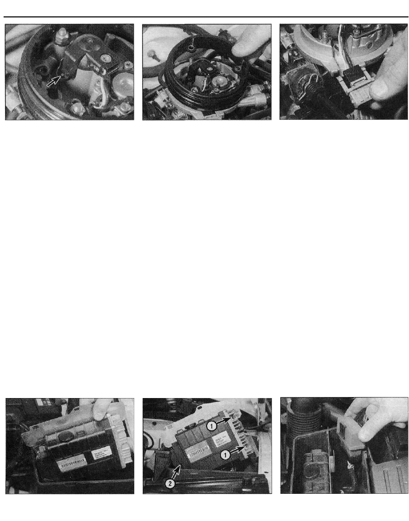
23 To remove the ECU, first disconnect the
battery.
24 Unclip the lid from the box, and slide out
the ECU and mounting plate. Disconnect the
wiring connector(s) from the ECU, slacken
and remove the bolts securing it to the
mounting plate, and remove it from the
vehicle (see illustrations).
14.19 Injector cap wiring connector is a
push fit in the throttle body
25 Refitting is a reverse of the removal
procedure, ensuring that the wiring
connectors are securely reconnected.
Fuel injection system relay unit
26 The relay unit is inside the plastic box
which is situated directly in front of the
battery.
27 To remove the relay unit, first disconnect
the battery.
28 Unclip the lid from the box, then unclip the
relay unit from the mounting plate, disconnect
the wiring connector and remove it from the
vehicle (see illustration).
29 Refitting is the reverse of removal,
ensuring that the relay unit is securely held in
position by its retaining clip.
Injector resistor
30 The injector resistor is inside the plastic
box which is situated directly in front of the
battery.
31 To remove the resistor, first disconnect
the battery.
32 Unclip the lid from the box, then slide out
the mounting plate and undo the resistor
retaining bolt. Disconnect the wiring
connector, and remove the resistor from the
vehicle (see illustration).
33 Refitting is a reversal of the removal
procedure.
14.24a Slide out the mounting plate . . .
14.24b . . . then undo the retaining
bolts (1), disconnect the wiring
connector (2), and remove the ECU
14.28 Removing the fuel injection system
relay unit
Fuel and exhaust systems - single-point fuel injection models 4B•9
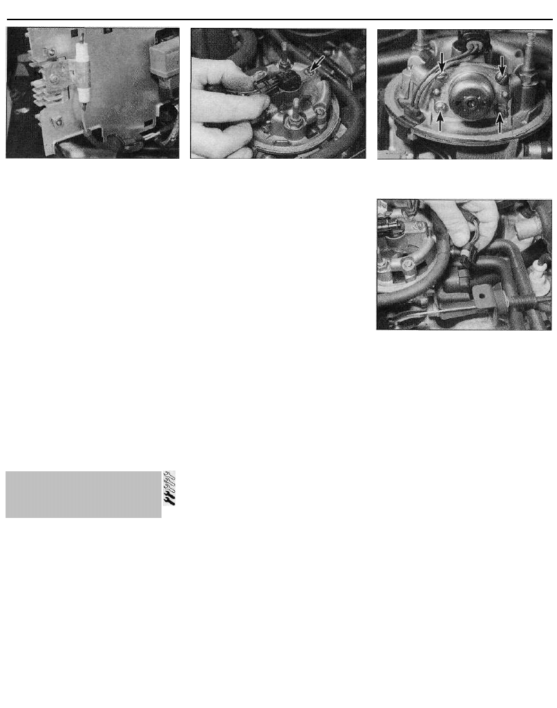
14.32 Injector resistor is mounted on the
rear of the ECU mounting plate
Crankshaft sensor (MA3.0 system)
- later 1360 cc models
34 The crankshaft sensor is situated on the
front face of the transmission (clutch) housing.
35 To remove the sensor, first disconnect the
battery negative terminal.
36 Trace the wiring back from the sensor to
the wiring connector, and disconnect it from
the main harness.
37 Prise out the rubber grommet, then undo
the retaining bolt and withdraw the sensor
from the transmission.
38 Refitting is a reverse of the removal
procedure. Ensure that the sensor retaining
bolt is securely tightened, and that the
grommet is correctly seated in the
transmission housing.
Vehicle speed sensor (MA3.0
system) - later 1360 cc models
39 The vehicle speed sensor is an integral
part of the speedometer drive housing. Refer
to Chapter 7A, Section 6 for removal and
refitting details.
Fuel injector
Note: Refer to the warning note at the start of
this Section before proceeding. If a faulty
injector is suspected, before condemning the
injector, it is worth trying the effect of one of
the proprietary injector-cleaning treatments. If
this fails, the vehicle should be taken to a
Citroen dealer for testing using the
appropriate specialist equipment. At the time
of writing, it appears that the fuel injector is
not available separately and, if faulty, the
complete upper throttle body assembly must
be renewed. Refer to a Citroen dealer for the
latest information.
1 Disconnect the battery negative terminal.
2 Slacken and remove the two nuts and
washers securing the intake duct to the
15.3 Disconnecting the injector wiring
connector. Injector retaining clip screw
(arrowed)
throttle body, and move the duct out of the
way. Remove the rubber sealing ring from the
top of the throttle body.
3 Release the retaining tangs, and disconnect
the injector wiring connector (see
illustration).
4 Undo the retaining screw, then remove the
retaining clip and lift the injector out of the
housing, noting its sealing ring. As the screw
is slackened, place a clean rag over the
injector, to catch any fuel spray which may be
released.
5 Refitting is a reverse of the removal
procedure, ensuring that the injector sealing
ring is in good condition.
Fuel pressure regulator
Note: Refer to the warning note in Section 1
before proceeding. At the time of writing, the
fuel pressure regulator assembly was not
available separately from the throttle body
assembly. Refer to a Citroen dealer for the
latest information. Although the unit can be
dismantled for cleaning, if required, it should
not be disturbed unless absolutely necessary.
6 Slacken and remove the two nuts and
washers securing the intake duct to the
throttle body, and move the duct out of the
way, along with its rubber sealing ring.
Disconnect the battery negative terminal.
7 Using a marker pen, make alignment marks
between the regulator cover and throttle
body, then undo the four retaining screws
(see illustration). As the screws are
slackened, place a clean rag over the cover,
to catch any fuel spray which may be
released.
8 Lift off the cover, then remove the spring
and withdraw the diaphragm, noting its
correct fitted orientation. Remove all traces of
dirt, and examine the diaphragm for signs of
splitting. If damage is found, it will apparently
be necessary to renew the complete upper
throttle body assembly, as described earlier in
this Section.
9 Refitting is a reverse of the removal
procedure, ensuring that the diaphragm and
cover are fitted the correct way around, and
that the retaining screws are securely
tightened.
15.7 Fuel pressure regulator is retained by
four screws (arrowed)
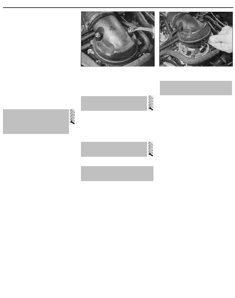
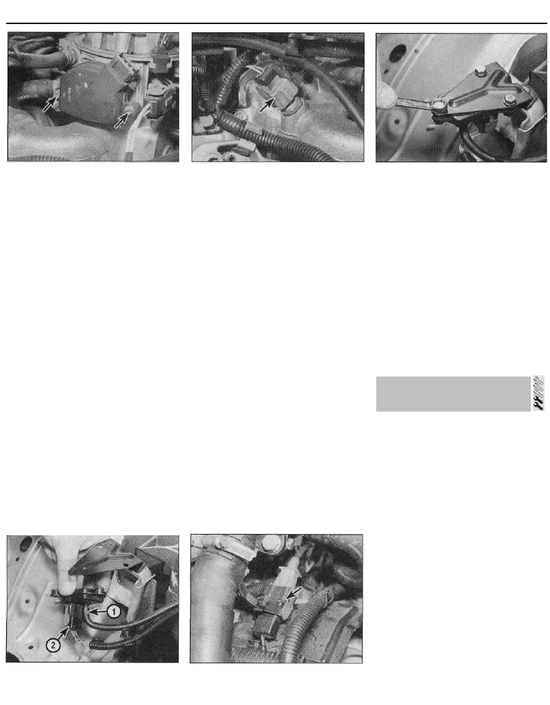
15.15 Disconnecting the stepper motor
wiring connector
Idle control auxiliary air valve -
G5.S2 system
10 The idle control auxiliary air valve is
situated directly behind the throttle body,
mounted onto the cylinder head.
11 To remove the valve, first disconnect the
battery.
12 Slacken the retaining clips, and
disconnect the two hoses from the side of the
valve. Mark the hoses to ensure they are
correctly reconnected on refitting.
13 Disconnect the wiring connector, then
undo the two retaining nuts and remove the
auxiliary air valve from the engine
compartment.
14 Refitting is a reverse of the removal
procedure.
Idle control stepper motor - G6.12
and G6.10 systems
Note: At the time of writing, it appears that the
stepper motor is not available separately and,
if faulty, the complete lower throttle body
assembly must be renewed as described
earlier in this Section. Refer to your Citroen
dealer for the latest information.
15 To remove the stepper motor, depress the
retaining tabs and disconnect the wiring
connector (see illustration). Undo the two
retaining screws, and withdraw the motor
from the rear of the throttle body assembly.
16 Refitting is a reverse of removal.
15 Magneti Marelli system
components -
removal and refitting
4B•10 Fuel and exhaust systems - single-point fuel injection models
15.18 Throttle potentiometer is secured to
the throttle body by two screws (arrowed)
Throttle potentiometer
17 Disconnect the battery negative terminal,
then depress the retaining tabs and
disconnect the wiring connector from the
throttle potentiometer.
18 Undo the two retaining screws, and
remove the throttle potentiometer from the
right-hand side of the throttle body assembly
(see illustration).
19 Refitting is a reversal of the removal
procedure, ensuring that the throttle
potentiometer tang is correctly engaged with
the throttle spindle.
Fuel/air mixture temperature
sensor
20 The fuel/air mixture temperature sensor is
screwed into the right-hand side of the inlet
manifold, and is removed as follows (see
illustration).
21 To remove the sensor, first disconnect the
battery negative terminal.
22 Disconnect the wiring connector, then
unscrew the fuel/air mixture temperature
sensor from the inlet manifold.
23 Refitting is a reverse of the removal
procedure, ensuring that the switch is
securely tightened.
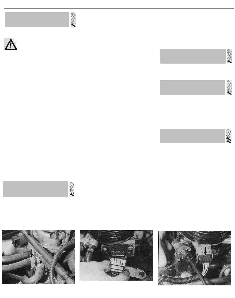
Manifold absolute pressure (MAP)
sensor
24 The MAP sensor is mounted on a bracket
15.20 The fuel/air mixture temperature
sensor (arrowed) is screwed into the right-
hand side of the inlet manifold
situated on the right-hand side of the engine
compartment, next to the alternator.
25 To remove the sensor, first disconnect the
battery negative terminal.
26 Slacken and remove the three retaining
nuts and bolts, then free the MAP sensor from
the bracket. Disconnect the wiring connector
and vacuum hose, and remove the sensor
from the engine compartment (see
illustrations).
27 Refitting is a reverse of the removal
procedure.
Coolant temperature sensor
28 Refer to Chapter 3, Section 6.
Crankshaft sensor
29 The crankshaft sensor is fitted to the top
of the transmission housing, beside the left-
hand end of the cylinder block.
30 To remove the sensor, first disconnect the
battery negative terminal.
31 Trace the wiring back from the sensor to
its wiring connector, then depress the
retaining tabs and disconnect it from the main
wiring harness. Release the wiring connector
from any relevant retaining clips (see
illustration).
32 To gain access to the sensor, it is
necessary to remove the metal plate from the
top of the transmission housing. The plate is
retained by one of the engine-to-transmission
15.26a Undo the three retaining bolts .
bolts, and by a second bolt securing the plate
to the top of the transmission.
33 With the plate removed, undo the bolt
securing the sensor to the transmission
housing, and remove the sensor from the
vehicle.
34 Refitting is a reverse of removal, ensuring
that the sensor retaining bolt is securely
tightened.
Electronic control unit (ECU)
35 Refer to paragraphs 22 to 25 of Sec-
tion 14.
Fuel injection system relay unit
36 Refer to paragraphs 26 to 29 of Sec-
tion 14.
15.26b . . . then release the MAP sensor
from its mounting bracket, and disconnect
the vacuum hose (1) and wiring connector (2)
15.31 The crankshaft sensor wiring
connector (arrowed) is situated on top of
the transmission housing
Removal
1124 cc and 1360 cc models
1 Remove the throttle body as described in
Section 12.
2 Drain the cooling system as described in
Chapter 1.
3 Slacken the retaining clip, and disconnect
the coolant hose(s) from the manifold.
4 Slacken the retaining clip, and disconnect
the vacuum servo unit hose from the left-hand
side of the manifold.
5 Make a final check that all the necessary
vacuum/breather hoses have been
disconnected from the manifold.
6 Unscrew the six retaining nuts, then
manoeuvre the manifold away from the head
and out of the engine compartment. Note that
there is no manifold gasket.
1580 cc models
7 Remove the throttle body as described in
Section 12.
8 Drain the cooling system as described in
Chapter 1.
9 Disconnect the wiring connector from the
fuel/air mixture temperature sensor, which is
situated on the right-hand side of the
manifold.
16 Inlet manifold -
removal and refitting
Fuel and exhaust systems - single-point fuel injection models 4B•11
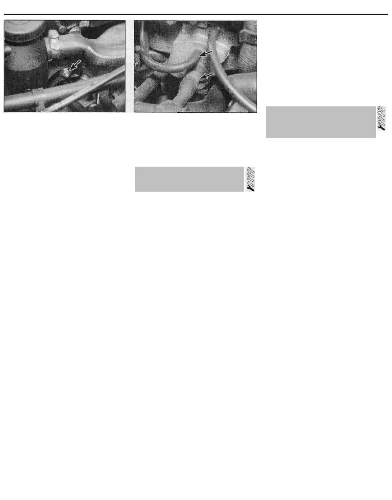
16.10 Oil filler/breather retaining nut
(arrowed) - 1580 cc models
16.12 Inlet manifold coolant hose and
MAP sensor hose (arrowed) -1580 cc
models
(b) Ensure that the manifold and cylinder
head sealing faces are clean and flat, and
fit the new manifold gaskets. Tighten the
manifold retaining nuts to the specified
torque.
(c) Reconnect the front pipe to the manifold
using the information given in Section 18.
(d) On 1580 cc models, refit the disturbed air
cleaner components as described in
Section 2.
18 Exhaust system -
general information, removal
and refitting
10 Undo the nut securing the oil
filler/breather to the side of the manifold, then
release the assembly from its retaining stud,
and position it clear of the manifold (see
illustration).
11 Undo the bolt securing the wiring/hose
support bracket to the top of the manifold,
and position the bracket clear of the manifold.
12 Disconnect the coolant hose and the MAP
sensor vacuum hose from the front of the
manifold (see illustration).
13 Undo and remove the six manifold
retaining nuts and washers, and remove the
manifold from the engine. Remove the gasket
and discard it - a new one should be used on
refitting.
Refitting
1124 cc and 1360 cc models
14 Refitting is the reverse of the removal
procedure, noting the following points:
(a) Ensure that the manifold and cylinder
head mating surfaces are clean and dry,
and apply a thin coating of suitable
sealing compound to the manifold mating
surface. Refit the manifold, and tighten its
retaining nuts to the specified torque.
(b) Ensure that all relevant hoses are
reconnected to their original positions,
and are securely held (where necessary)
by their retaining clips.
(c) Refit the throttle body as described in
Section 12.
(d) On completion, refill the cooling system
as described in Chapter 1.
1580 cc models
15 Refitting is a reverse of the removal
procedure, noting the following points:
(a) Ensure that the manifold and cylinder
head mating surfaces are clean and dry,
and fit a new manifold gasket Refit the
manifold, and tighten its retaining nuts to
the specified torque.
(b) Ensure that all relevant hoses are
reconnected to their original positions,
and are securely held (where necessary)
by the retaining clips.
(c) Refit the throttle body as described in
Section 12.
(d) On completion, refill the cooling system
as described in Chapter 1.
Removal
1124 cc and 1360 cc models
1 Refer to Chapter 4A, Section 16, noting that
the lambda (oxygen) sensor wiring connectors
should be disconnected. Alternatively, care
must be taken to support the front pipe, to
avoid any strain being placed on the sensor
wiring.
1580 cc models
2 Remove the air cleaner housing and
mounting bracket, as described in Section 2.
3 Slacken the clip securing the hot-air intake
hose to the bottom of the air temperature
control valve, then disconnect the hose from
the manifold shroud and remove it from the
engine compartment.
4 Undo the remaining manifold shroud
retaining bolts, and remove the shroud.
5 Firmly apply the handbrake, then jack up
the front of the vehicle and support it on axle
stands.
6 Slacken and remove the two nuts securing
the front pipe flange joint to the manifold, and
recover the springs. Remove the bolts, then
free the front pipe from the manifold, and
recover the wire-mesh sealing ring. Either
support the front pipe to avoid placing any
strain on the lambda sensor wiring (where
fitted), or disconnect the wiring connectors.
7 Undo the eight retaining nuts securing the
manifold to the head. Manoeuvre the manifold
out of the engine compartment, and discard
the manifold gaskets.
Refitting (all models)
8 Refitting is the reverse of the removal
procedure, noting the following points:
(a) Examine all the exhaust manifold studs for
signs of damage and corrosion; remove
all traces of corrosion, and repair or
renew any damaged studs.
General information
1 On 1124 cc and 1360 cc models, the
exhaust system consists of four sections; the
front pipe, the catalytic converter, the
intermediate pipe, and the tailpipe and main
silencer box. All exhaust sections are joined
by a flanged joint. The front pipe joints are
secured by nuts and bolts, the catalytic
converter joint being of the spring-loaded ball
type, to allow for movement in the exhaust
system. The catalytic converter-to-
intermediate pipe joint and the intermediate
pipe-to-silencer joint are secured by a
clamping ring.
2 On 1580 cc models without a catalytic
converter, the exhaust system consists of two
sections; the front pipe and intermediate
silencer box, and the tailpipe and main
silencer box. On 1580 cc models with a
catalytic converter, the system consists of
three sections; the front pipe and catalytic
converter, the intermediate pipe and silencer
box, and the tailpipe and main silencer box.
The front pipe-to-manifold joint is of the
spring-loaded ball type, to allow for
movement in the exhaust system, the other
joint(s) being secured by a clamping ring.
3 The system is suspended throughout its
entire length by rubber mountings.
Removal
4 Each exhaust section can be removed
individually, or alternatively, the complete
system can be removed as a unit. Even if only
one part of the system needs attention, it is
often easier to remove the whole system and
separate the sections on the bench.
5 To remove the system or part of the
system, first jack up the front or rear of the
car, and support it on axle stands.
Alternatively, position the car over an
inspection pit, or on car ramps.
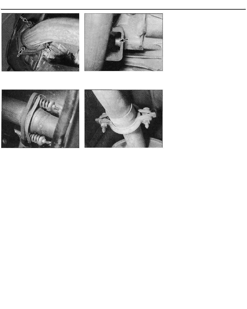
Front pipe -1124 cc and 1360 cc
models
6 Trace the wiring back from the lambda
(oxygen) sensor to its wiring connectors, and
disconnect it from the main wiring harness.
7 Undo the nuts securing the front pipe
flange joint to the manifold, and the single bolt
17 Exhaust manifold -
removal and refitting
4B•12 Fuel and exhaust systems - single-point fuel injection models
18.7a Front pipe-to-manifold retaining 18.7b . . . and front pipe mounting bolt
nuts (arrowed)... (arrowed) - 1124 cc and 1360 cc models
(viewed from underneath)
18.8 Front pipe-to-catalytic converter joint
- 1124 cc and 1360 cc models
securing the front pipe to its mounting bracket
(see illustrations). Separate the flange joint,
and collect the gasket.
8 Slacken and remove the two nuts securing
the front pipe to the catalytic converter, and
recover the spring cups and springs (see
illustration). Remove the bolts, then withdraw
the front pipe from underneath the vehicle,
taking care not to damage the lambda sensor,
and recover the wire-mesh gasket from the
joint.
Front pipe assembly -1580 cc models
without a catalytic converter
9 Slacken and remove the two nuts securing
the front pipe to the manifold, and recover the
spring cups and springs. Remove the bolts,
then release the front pipe from the manifold,
and recover the wire-mesh gasket from the
joint.
10 Slacken the front pipe-to-tailpipe
clamping ring bolts, and disengage the clamp
from the flange joint (see illustration).
11 Free the front pipe assembly from its
mounting rubbers, and withdraw it from
underneath the vehicle.
Front pipe assembly -1580 cc models
with a catalytic converter
12 Trace the wiring back from the lambda
(oxygen) sensor to its wiring connectors, and
disconnect it from the main wiring harness.
13 Disconnect the front pipe from the
manifold and intermediate pipe as described
18.10 Typical exhaust system clamping
ring
above in paragraphs 9 and 10, then remove
the front pipe assembly from underneath the
vehicle. Be careful not to drop it - the catalytic
converter is fragile.
Catalytic converter -1124 cc and 1360
cc models
14 Undo the two nuts securing the front pipe
flange joint to the catalytic converter. Recover
the springs and spring cups, and withdraw the
bolts.
15 Slacken the catalytic converter-to-
intermediate pipe clamping ring bolts, and
disengage the clamp from the flange joint.
16 Free the catalytic converter from the
intermediate pipe, then withdraw it from
underneath the vehicle. Be careful not to drop
it - it is fragile. Recover the wire-mesh gasket
from the front pipe joint.
Intermediate pipe -1124 cc and 1360
cc models
17 Slacken the clamping ring bolts, and
disengage the clamps from both the
intermediate pipe flange joints.
18 Free the intermediate pipe from its
mounting rubbers, then disengage it first from
the tailpipe and then from the catalytic
converter. Remove the intermediate pipe from
underneath the vehicle.
Intermediate pipe -1580 cc models
with a catalytic converter
19 Slacken the clamping ring bolts, and
disengage the clamps from both the
intermediate pipe flange joints.
20 Free the intermediate pipe from its
mounting rubbers, then disengage it first from
the tailpipe and then from the front pipe.
Remove the intermediate pipe from
underneath the vehicle.
Tailpipe - all models
21 Slacken the intermediate pipe-to-tailpipe
clamping ring bolts, and disengage the clamp
from the flange joint.
22 Unhook the tailpipe from its mounting
rubbers, and remove it from the vehicle.
Complete system - all models
23 Using the information given under the
relevant sub-heading above, unbolt the front
pipe from the manifold, removing the bolt
securing the front pipe to its mounting bracket
and/or disconnecting the lambda sensor
wiring (as applicable). Free the system from all
its mounting rubbers, and withdraw it from
under the vehicle.
Heat shield(s) - all models
24 The heat shields are secured to the
underside of the body by various nuts and
bolts. Each shield can be removed once the
appropriate exhaust section has been
removed. If the shield is being removed to
gain access to a component located behind it,
it may prove sufficient in some cases to
remove the retaining nuts and bolts, and
simply lower the shield, without disturbing the
exhaust system.
Refitting
25 Each section is refitted by reversing the
removal procedure, noting the following
points:
(a) Ensure that all traces of corrosion have
been removed from the flanges, and
renew all necessary gaskets.
(b) Inspect the rubber mountings for signs of
damage or deterioration, and renew as
necessary.
(c) Prior to assembling a spring-loaded ball
type joint, a smear of high-temperature
grease should be applied to the joint
mating surfaces. Citroen recommend the
use of Gripcott AF G2 grease (available
from your Citroen dealer).
(d) On joints which are secured by clamping
rings, apply a smear of exhaust system
jointing paste to the joint mating surfaces,
to ensure an gas-tight seal. Tighten the
clamping ring nuts evenly and
progressively to the specified torque, so
that the clearance between the clamp
halves is equal on either side.
(e) Before tightening the exhaust system
fasteners, ensure that all rubber
mountings are correctly located, and that
there is adequate clearance between the
exhaust system and vehicle underbody.
Wyszukiwarka
Podobne podstrony:
zx 01
Matematyka PG PP kl2 MPZ sprawdzian 04B arkusz
zx 00
zx 04d
zx 08
elektro wyklad 04b
PR1 04b
04b RACHUNEK ZYSKÓW I STRAT
zx 10
zx 04c
04b BUDOWA CIALA STALEGOid 53 Nieznany (2)
zx 07a
0656PWsrTz1 Rysunek 04b
zx 02a
PREZENTACJA FIRMY „X
FIG-04B
więcej podobnych podstron