1
Chapter 2 Fluid Statics
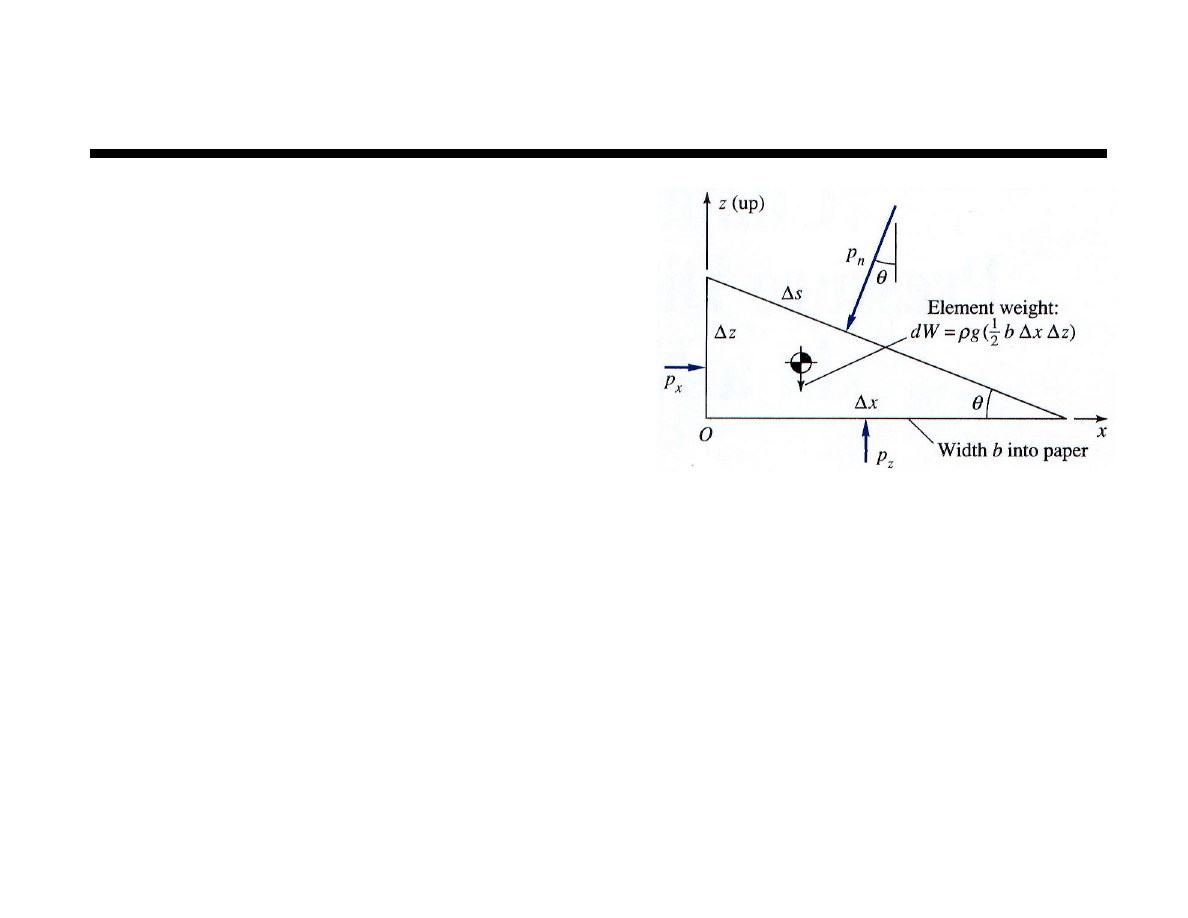
Fluid Statics
3 concepts can be developed
from a force analysis on
a triangular fluid element
1. Pressure is constant along
a horizontal plane
2. Pressure at a point is
independent of direction
3. Pressure change in any direction is proportional to
Fluid density
Gravitational acceleration
Change in vertical depth
These basic concepts are key to the solution of fluid
statics problems
2
Chapter 2 Fluid Statics
Fluid Statics
The concepts presented on the previous slide lead
to following for a static fluid
1. Two points at the same depth have the same pressure
2. The orientation of a surface has no bearing on the
pressure at a point
3. Vertical depth is key in determining pressure change
A general force analysis
on a fluid in motion
with constant properties,
ρ
and
µ
, produces
!p =
" g # a
{
}
+
µ!
2
V
3
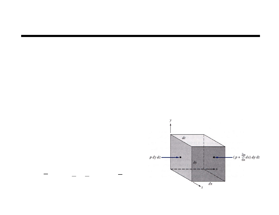
Chapter 2 Fluid Statics
Fluid Statics
Pressure change in a fluid in general depends on
1. Effects of fluid statics
Chapter 2
2. Inertial effects
Chapter 3
3. Viscous effects
Chapters 6 & 7
For problems involving both 1 & 2, the net
acceleration vector controls magnitude and
direction of pressure gradient
The equation can be simplified for a fluid at rest
! & g
(
)
! & a
(
)
µ
!
2
V
(
)
g
! a
{
}
!p =
" g # a
{
}
+
µ!
2
V
$ !p =
" g
%p
%x
= 0
%p
%y
= 0
%p
%z
=
dp
dz
= #
" g
p
2
# p
1
= #
" gdz
1
2
&
4
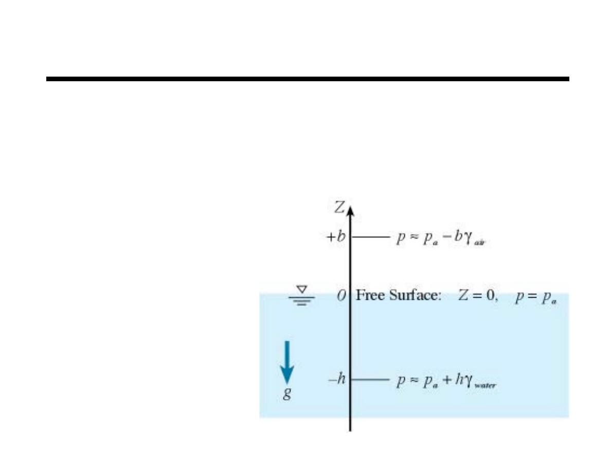
Chapter 2 Fluid Statics
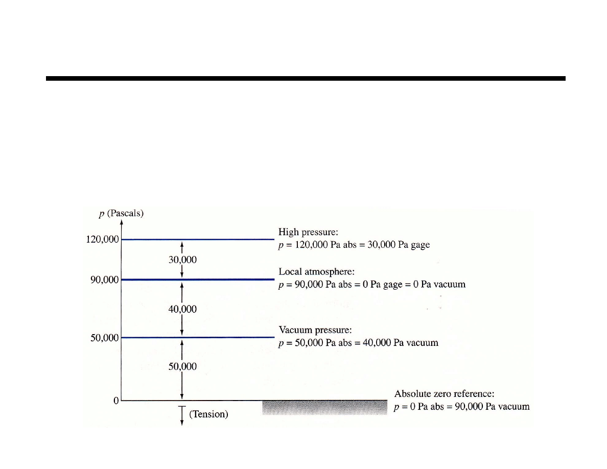
Pressure Reference
Absolute pressure, p
abs
p relative to absolute zero
Gage pressure , p
gage
p relative p
atm
when p > p
atm
Vacuum pressure , p
gage
p relative p
atm
when p < p
atm
p
atm
pressure due to local atmosphere only (std p
atm
at sea level)
5
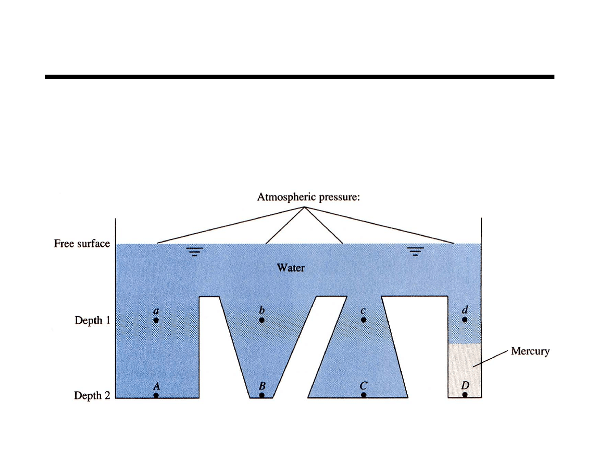
Chapter 2 Fluid Statics
Hydrostatic Pressure in Liquids
a, b, c & d at same pressure
A, B & C at same pressure (different from above)
D different from A, B & C
6
Chapter 2 Fluid Statics
Hydrostatic Pressure in Liquids
For incompressible fluids (liquids)
integrates to
z
2
– z
1
> 0 for z
2
above z
1
but p
2
– p
1
< 0
For incompressible,
static fluid
p
2
! p
1
= !
" gdz
1
2
#
p
2
! p
1
= !
"g z
2
! z
1
(
)
p
2
! p
1
= !
"g z
2
! z
1
(
)
= !
# z
2
! z
1
(
)
7
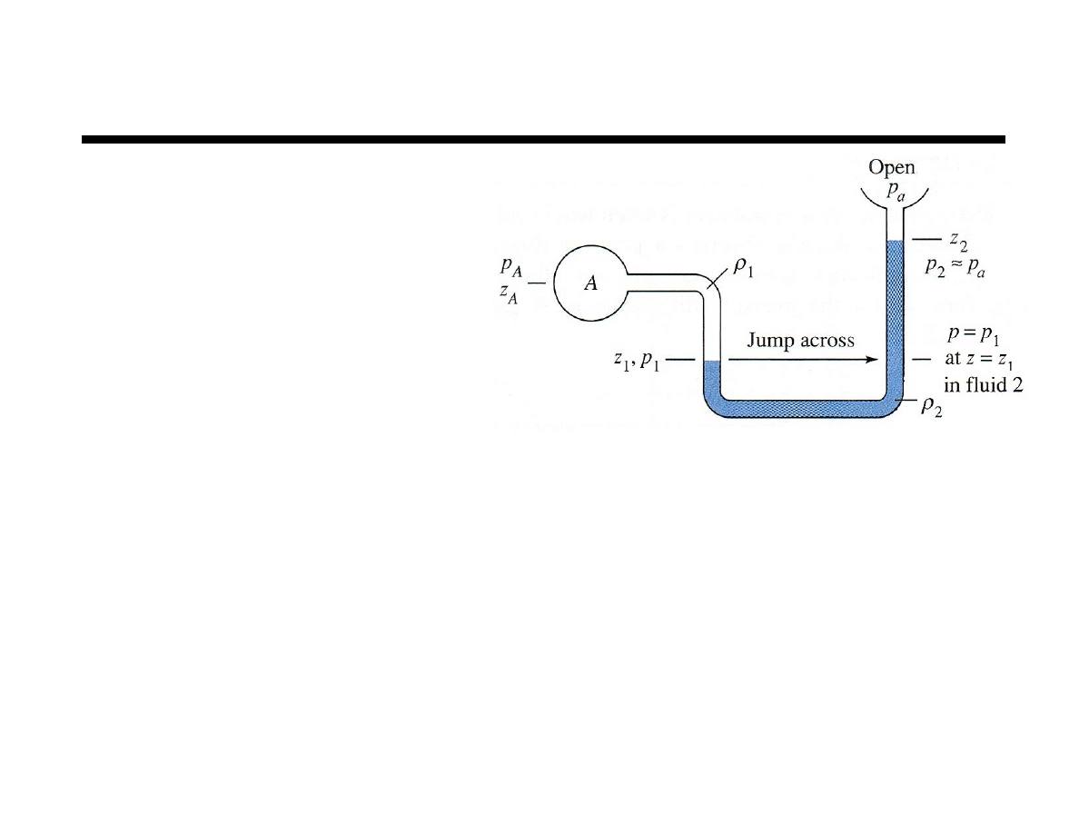
Chapter 2 Fluid Statics
The Manometer
A U–tube, multi–fluid manometer
Overall pressure
difference
Note: z is positive going up and
z
A
> z
1
z
1
< z
2
z
2
< z
a
p
A
! p
a
= p
A
! p
1
(
)
+ p
1
! p
2
(
)
+ p
2
! p
a
(
)
p
A
! p
a
= !
"
1
g z
A
! z
1
(
)
!
"
2
g z
1
! z
2
(
)
!
"
air
g z
2
! z
a
(
)

8
Chapter 2 Fluid Statics
Steps to Analyze a Manometer
1.
On a schematic of the manometer label points at each end and at
each intermediate fluid interface
2.
Express overall pressure difference in terms of appropriate
intermediate pressures
3.
Express each intermediate pressure difference in terms of
appropriate specific weight times elevation change,
ρ
gh
Take care to
1.
Include all pressure differences
2.
Use correct
Δ
z and
ρ
g for each fluid
3.
Use correct sign for each
Δ
z (if
Δ
p is p
A
–p
1
then
Δ
z is z
A
–z
1
)
4.
Be careful with units
p
A
! p
B
= p
A
! p
1
(
)
+ p
1
! p
2
(
)
+ p
2
! p
B
(
)
p
A
! p
B
= !
"
1
g z
A
! z
1
(
)
!
"
2
g z
1
! z
2
(
)
!
"
air
g z
2
! z
B
(
)
9
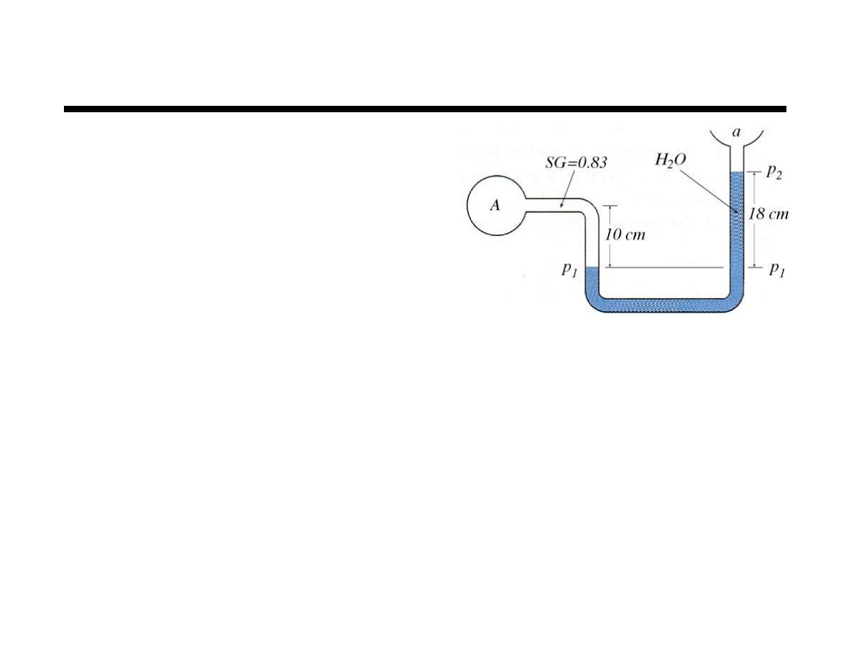
Chapter 2 Fluid Statics
Example
Determine the gage pressure at A
if p
a
=101.3 kPa and the fluid at
A is Meriam red oil No. 3
Neglect air term
!
g
( )
w
=
"
w
= 9790 N/m
3
!
g
( )
air
=
"
air
= 11.8 N/m
3
!
g
( )
A
=
"
A
= SG
( )
!
g
( )
w
= 0.83
(
)
9790
(
)
= 8126 N/m
3
p
A
! p
a
= p
A gage
= p
A
! p
1
(
)
+ p
1
! p
2
(
)
+ p
2
! p
a
(
)
p
A gage
= !
" g
( )
A
z
A
! z
1
(
)
!
" g
( )
w
z
1
! z
2
(
)
!
" g
( )
air
z
2
! z
B
(
)
p
A gage
= ! 8126 N/m
3
(
)
0.1 m
(
)
! 9790 N/m
3
(
)
0.18 m
(
)
= 949.6 N/m
3
10
Chapter 2 Fluid Statics
Hydrostatic Forces on Gases
Gasses are compressible, thus, density is variable
For an ideal gas the expression for pressure gradient is
For isothermal conditions T=T
o
Up to an altitude of 36,000 ft the mean
atmospheric temperature decreases linearly
Substitute the linear temperature profile into expression for pressure
dp
dz
= !
"
g
= !
p
RT
g
or
dp
p
1
2
#
= ln
p
2
p
1
= !
g
R
dz
T
1
2
#
p
2
= p
1
exp
g z
2
! z
1
(
)
RT
o
"
#
$
%
&
'
T
! T
o
" B z
T
o
= 518˚R = 288˚K B = 0.00357˚R/ft = 0.0065˚K/m
p
= p
a
1
!
B z
T
o
"
#$
%
&'
g / RB
( )
g / RB
( )
= 5.26 for air and R = 287
m
2
s
2
˚K
11
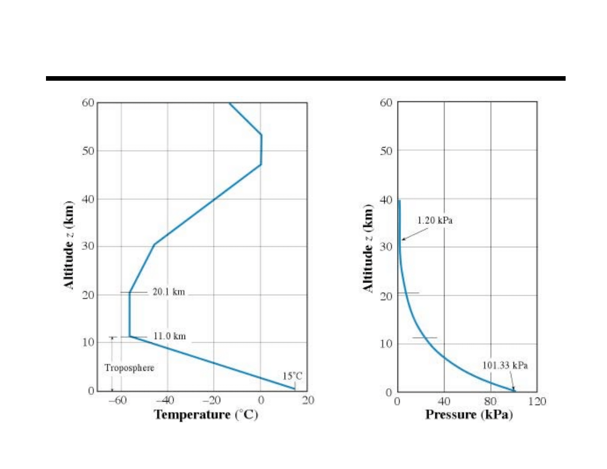
Chapter 2 Fluid Statics
Standard Atmosphere

12
Chapter 2 Fluid Statics
Forces on Plane Surfaces
The force exerted on a submerged surface relate to
the weight of fluid bearing on the surface
A container with a flat horizontal bottom surface
area A
b
and water depth h will experience
a downward force on its bottom of
Additional effort is required to determine the forces
(horizontal and vertical) on non–horizontal
submerged surfaces
F
=
! hA
b
13
Chapter 2 Fluid Statics
Force on Plane Surface
Consider the surface
as shown below
At any point
Total force on plate
Force equal to pressure at centroid times
area independent of shape or angle
p
= p
a
+
! h
F
=
pdA
A
!
=
p
a
+
" h
(
)
dA
A
!
= p
a
A
+
" hdA
A
!
= p
a
A
+
" sin# $ dA
A
!
= p
a
A
+
" sin# $
CG
A
= p
a
A
+
" h
CG
A
F
= p
CG
A
!
CG
=
1
A
!dA
A
"
h
CG
= sin
# !
CG
14
Chapter 2 Fluid Statics
Center of Pressure (CP)
Resultant force at CP produces
an equivalent moment
F
y CP
= ypdA
A
!
= y p
a
+
" #
sin
$
(
)
dA
A
!
=
"
sin
$
y
#
dA
A
!
=
"
sin
$
y
#
CG
% y
(
)
dA
A
!
=
"
sin
$ #
CG
y dA
A
!
% y
2
dA
A
!
(
)
F
y CP
= %
"
sin
$
I
xx
y
CP
= %
"
sin
$
I
xx
p
CG
A
similarly
x
CP
= %
"
sin
$
I
xy
p
CG
A
15
Chapter 2 Fluid Statics
Forces on Plane Surfaces
x
CP
& y
CP
both measured with respect to centroid of surface
x
CP
& y
CP
both measured in the inclined plane of the surface
Special Case: most problems involving a single, homogeneous
fluid pressure atmospheric is neglected and the fluid specific
weight cancels in the x
CP
& y
CP
expressions
Summary
Resultant force is determined from product of p
CG
and area
The centroid used to determine magnitude of force not force location
Resultant force location at CP – y
CP
below centroid and x
CP
to one side
x
CP
= 0 for surfaces with vertical symmetry plane
F
=
!
h
CG
A y
CP
= "
I
xx
sin
#
h
CG
A
x
CP
= "
I
xy
sin
#
h
CG
A
16
Chapter 2 Fluid Statics
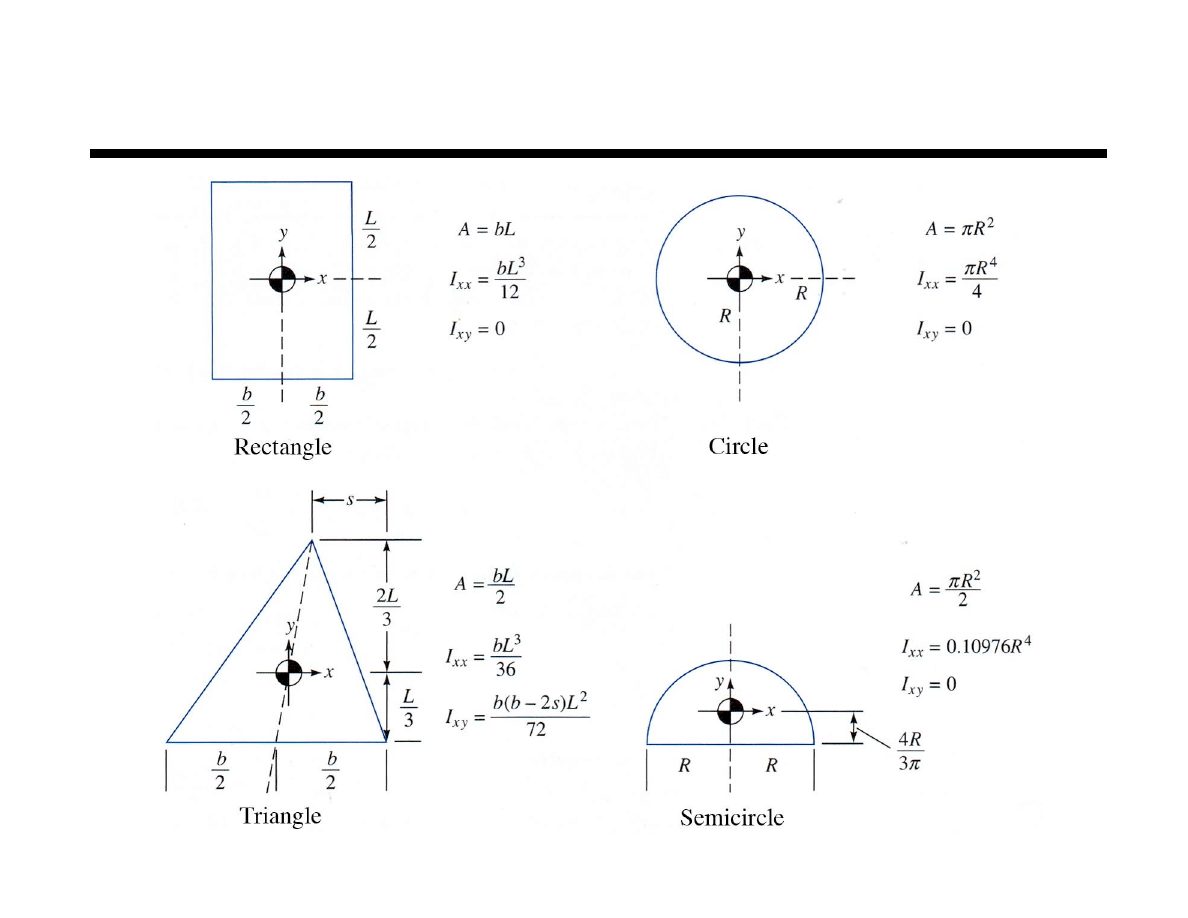
Centrodial Moments of Inertia
17
Chapter 2 Fluid Statics
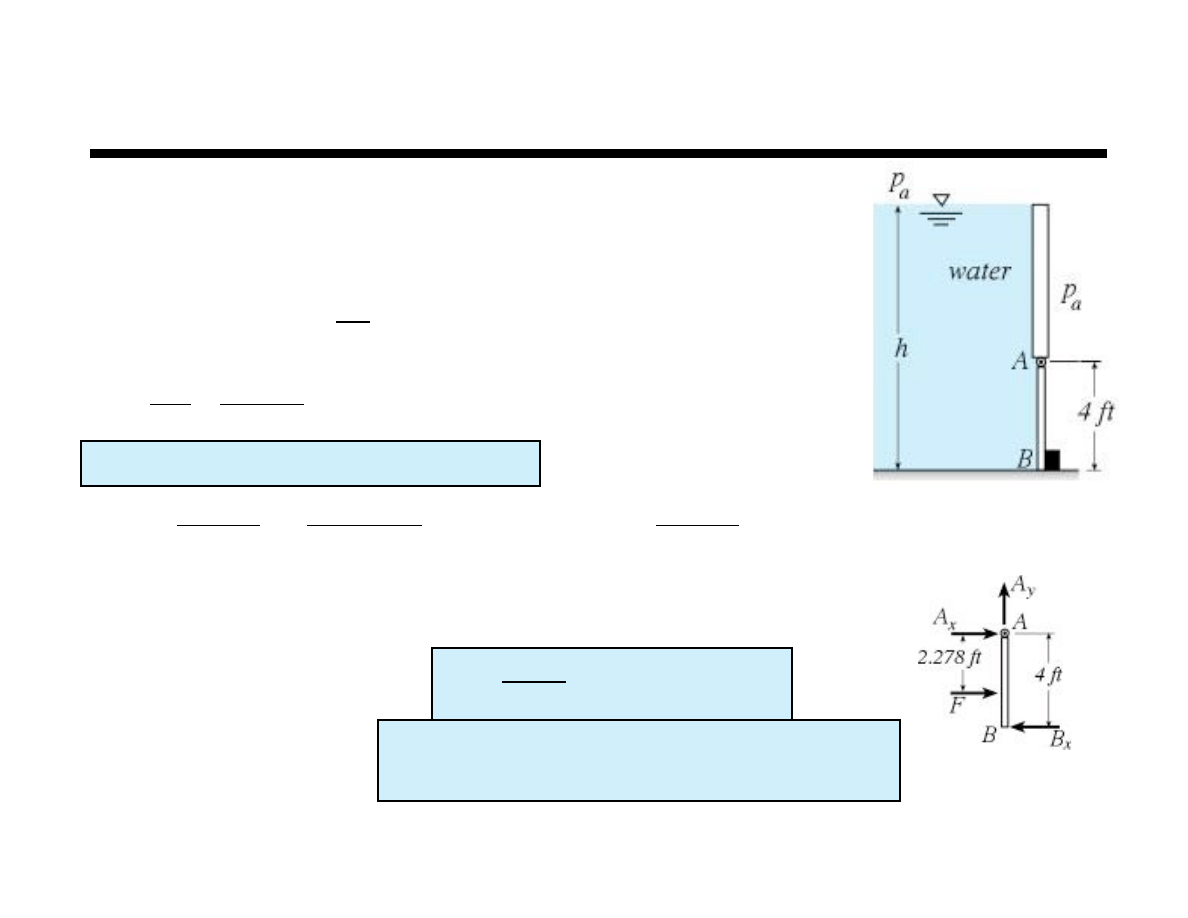
Example
Gate AB is 5 ft wide into the plane, hinged at A, and restrained
by a stop at B. The water is 20˚C. Compute (a) the force on
stop B and (b) the reactions at A if the water depth h = 9.5 ft.
CP is in center of gate front to back and 2.278 ft from A
p
a
cancels
! = 62.4
lbf
ft
3
h
CG
= 9.5 " 2 = 7.5ft
# = 90˚ sin(#) = 1
I
xx
=
bL
3
12
=
4
( )
5
3
( )
12
= 41.67ft
4
I
xy
= 0ft
4
A
= 4
( )
5
( )
= 20ft
2
F
=
! h
CG
A
= 62.4
(
)
7.5
( )
20
( )
= 9360lbf
y
CP
= "
I
xy
sin
#
h
CG
A
= "
41.67
(
)
1
( )
7.5
( )
20
( )
= "0.278ft x
CP
= "
I
xy
sin
#
h
CG
A
= 0ft
M
A
!
= 0 = 2.278
(
)
F
" 4B
x
# B
x
=
2.278
4
F
= 5330.5lbf $
F
x
!
= 0 = A
x
+ F " B
x
# A
x
= B
x
" F = 5330.5 " 9360 = "4074.8lbf $
A
y
= 0lbf
18
Chapter 2 Fluid Statics
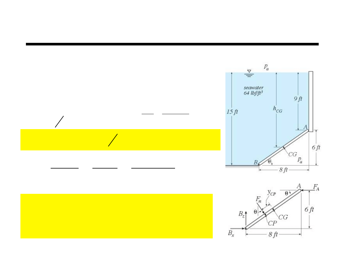
Example
A 5 ft wide gate hinged at B holds seawater as shown. Find
Net hydrostatic force gate
Horizontal force on wall at A
Hinge reactions at B
neglect p
a
A
= 10ft
( )
5 ft
( )
= 50ft
2
!
= tan
"1
6
8
( )
= 36.87˚
F
n
= p
CG
A
=
#
h
CG
A
= 64 lbf
ft
3
(
)
12 ft
( )
50 ft
2
(
)
= 38,400 lbf !
y
CP
= !
I
xx
" sin#
p
CG
A
= !
I
xx
sin
#
h
CG
A
= !
417 ft
4
(
)
0.6
( )
12 ft
( )
50 ft
2
(
)
= !0.417ft
x
CP
= 0 due to symmetry
M
B
$
= 0 = 6 F
A
! 5 ! 0.417
(
)
F
n
% F
A
= 29,331lbf &
F
x
$
= 0 = B
x
+ F
n
sin
# ! F
A
% B
x
= 6,291 lbf '
F
z
$
= 0 = B
z
! F
n
cos
# % B
z
= 30,720 lbf (
CG in center of gate
h
CG
= 9ft + 3ft=12ft
I
xx
=
bh
3
12
=
5
( )
10
3
( )
12
= 417ft
4
19
Chapter 2 Fluid Statics
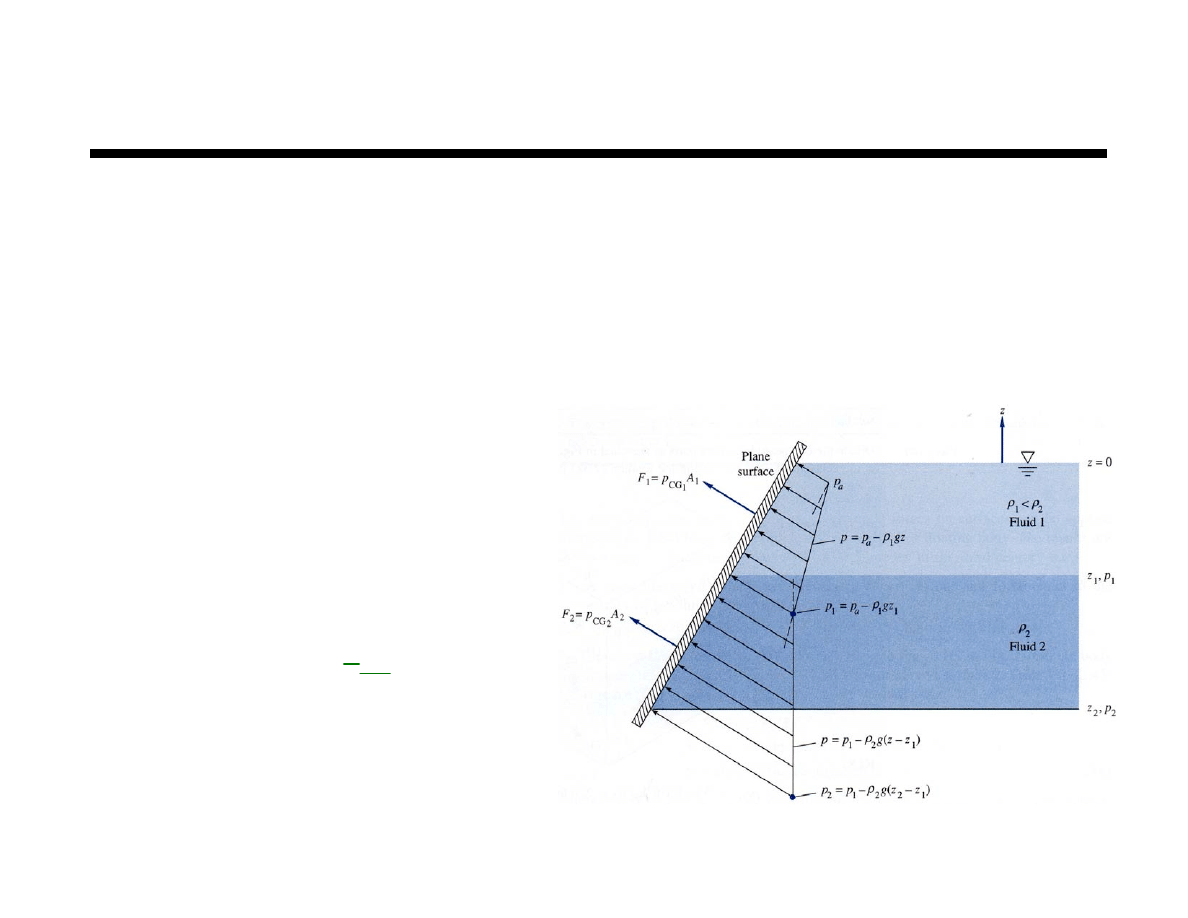
The portion of the surface in each layer must be
considered separately
Identify the area of surface in contact with each layer
Locate CG
j
for portion of surface in layer
j
Determine pressure at CG
j
Calculate force on portion
of surface in layer
j
Calculate y
CP
& x
CP
for layer
j
Repeat for each layer
Combine forces via vector algebra
Plane Surfaces in Layered Fluids
F
j
= p
CG
j
A
j
20
Chapter 2 Fluid Statics
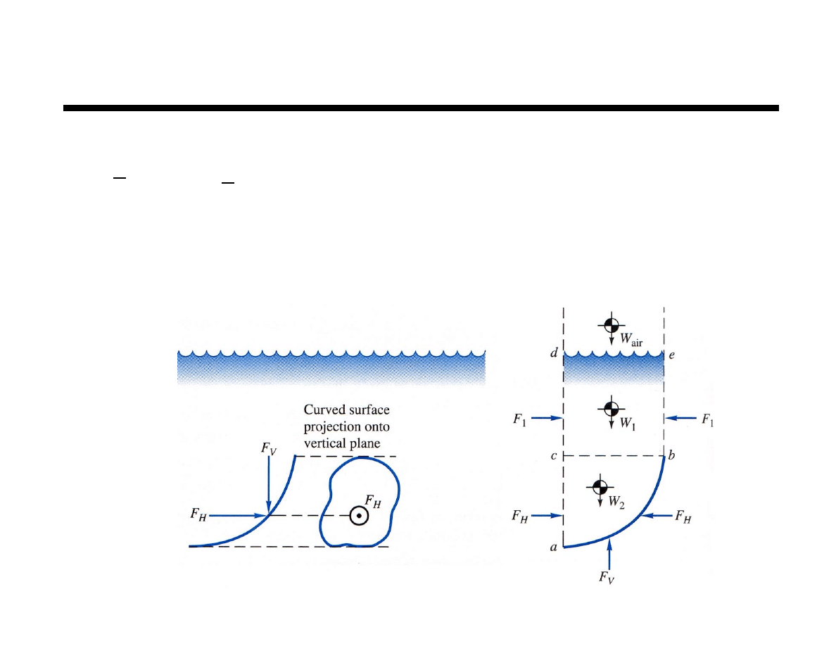
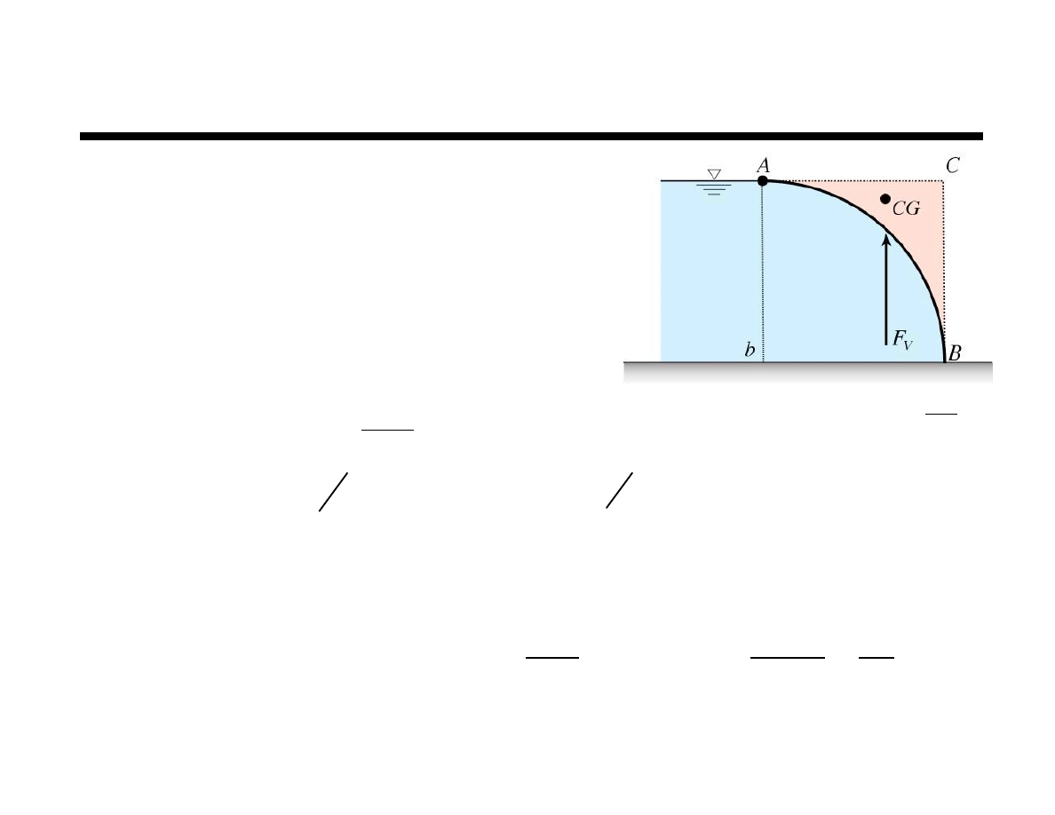
Forces on Curved Surfaces
The force could be determined from
This approach may be avoided by considering the
vertical and horizontal forces separately
F
=
p
!n
( )
dA
A
"
F
V
= W
air
+ W
1
+ W
2
& F
H
= p
CG
A
V
21
Chapter 2 Fluid Statics
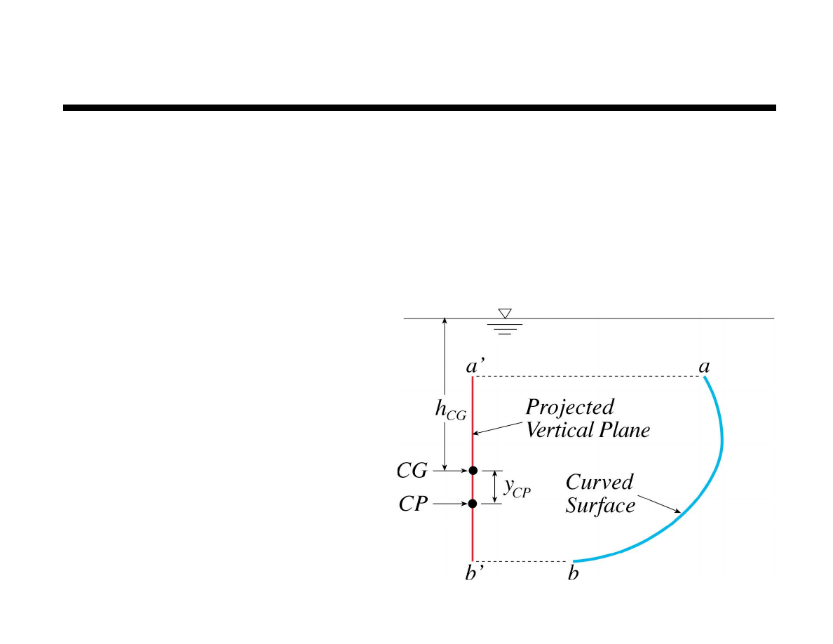
Horizontal Force Component
The horizontal force component on a curved surface
is equal to the force on the plane area formed by a
projection of the curved surface onto a vertical
plane normal to the component
Horizontal force acts
through the CP of the
projected area
(not the CG)

22
Chapter 2 Fluid Statics
Horizontal Force Component
To determine the horizontal force component on a
curved surface in a hydrostatic fluid
Project curved surface onto appropriate vertical plane
Perform all further calculations on vertical plane
Determine location of centroid (CG) of vertical plane
Determine depth of centroid (h
CG
of vertical plane)
Determine pressure at
centroid of vertical plane
Calculate where A is the curved surface
projected area on the vertical plane
F
h
passes through center of pressure in vertical plane
All analysis performed on vertical plane projection
p
CG
=
! h
CG
F
H
= p
CG
A
V
23
Chapter 2 Fluid Statics
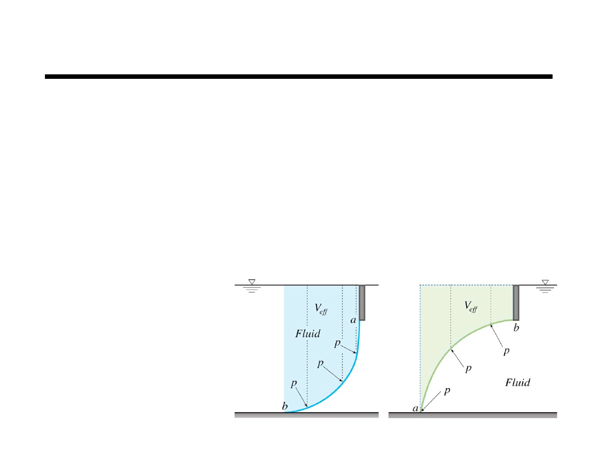
Vertical Force Component
The vertical force component on a curved surface is
equal to the weight of the effective column of fluid
Effective column of fluid is used because there may not be
fluid above the surface – rather identify the the column f
fluid that would be required to exert the pressure at each
location of the surface
Identify curved surface in contact with fluid
Identify pressure at each point on curved surface
Identify height
of fluid required
to develop pressure
These collective
heights combine to
form the effective
column of fluid
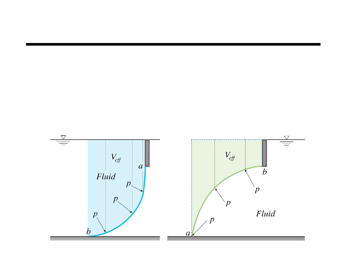
24
Chapter 2 Fluid Statics
Vertical Force Component
The vertical force acts vertically through the centroid (CG)
of the effective column of fluid
Identify effective column of fluid necessary to cause pressure at surface
Determine volume of effective column of fluid
Calculate weight of effective column of fluid
F
V
passes through the centroid of effective column of fluid
F
V
=
!
V
eff
25
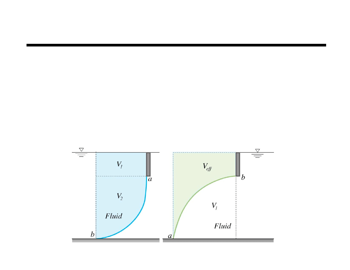
Chapter 2 Fluid Statics
Finding Location of Centroid of V
eff
Centroid – location where a point, area, volume,
or mass can be placed to yield the same first
moment of the distributed area, volume, mass, etc.
For example
x
CG
V
1
=
xdV
V
1
!
If V
eff
= V
1
+ V
2
then x
CG
V
eff
= x
1
V
1
+ x
2
V
2
If V
eff
= V
eff
then V
T
= V
eff
+ V
1
and x
T
V
T
= x
1
V
1
+ x
CG
V
eff
26
Chapter 2 Fluid Statics
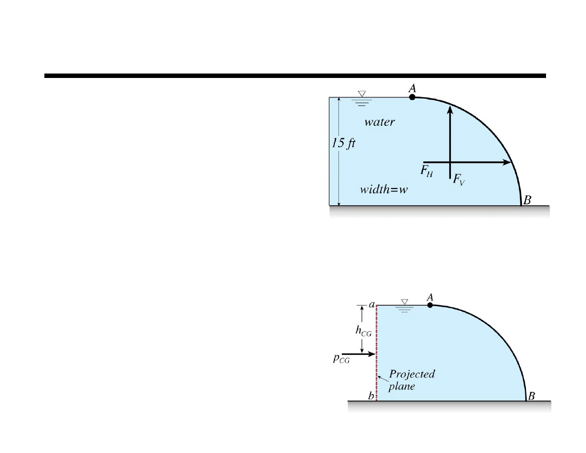
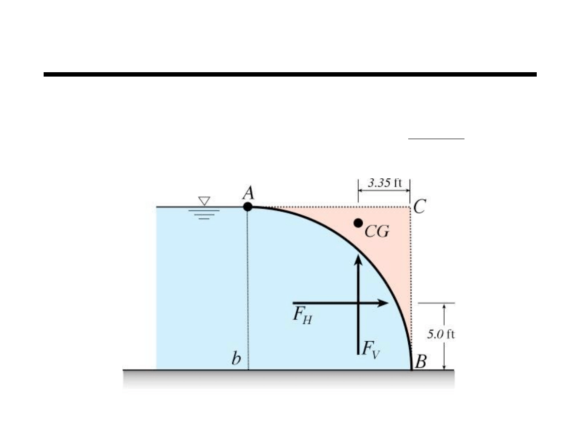
Example
Gate AB holds back 15 ft of water.
Neglecting the weight of the gate,
determine the magnitude (per unit
width) and location of the hydrostatic
forces on the gate and the resisting
moment at B.
Horizontal component
Project curved surface onto vertical plane
Locate centroid of vertical projection
Find pressure at centroid of vertical projection
All calculations done with projected area
Curved surface projects onto
plane a–b as a rectangle 15 ft by w
(not a quarter circle)
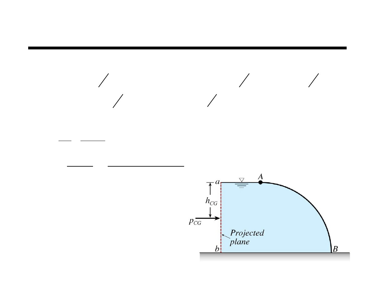
27
Chapter 2 Fluid Statics
Example
Horizontal component
Location
!
=
"
g
= 62.4 lbf
ft
3
h
CG
= 7.5ft p
CG
=
!
h
CG
= 62.4 lbf
ft
3
(
)
7.5 ft
(
)
= 468lbf
ft
2
F
H
= p
CG
A
= 468lbf
ft
2
(
)
15 ft
( )
w
#$
%& = 7020 w lbf ft of width '
I
xx
=
bh
3
12
=
w 15
3
( )
12
= 281.25 wft
4
y
CG
= !
I
xx
sin
"
h
CG
A
= !
281.25 w ft
4
(
)
sin 90˚
(
)
7.5 ft
(
)
15 ft
( )
w
(
)
= !2.5ft
that is 2.5 ft below CG, 5 ft above bottom
or 9 ft below the free surface
28
Chapter 2 Fluid Statics
Example
Vertical component
FV equals the weight of the effective fluid
column above the curved surface (in pink)
What volume of fluid will produce actual
pressure distribution on curved surface?
Location — F
V
acts through centroid of effective volume (volume ABC)
use concept of first moment of area (moments about left side of figure)
CG of quarter circle is
4 R
3
!
V
eff
= V
ABC
V
rec
= V
qc
+ V
ABC
V
ABC
= V
rec
! V
qc
V
ABC
= V
eff
= 15
2
( )
w
!
"
15
2
( )
4
w
= 48.29wft
3
F
V
=
# V
eff
= 62.4 lbf
ft
3
(
)
48.29 w ft
3
(
)
= 3013 w lbf
ft of width $
A
rec
= A
qc
+ A
ABC
M
rec
= M
qc
+ M
ABC
M
ABC
= M
rec
! M
qc
x
CG
A
ABC
= x
rec
A
rec
! x
qc
A
qc
x
CG
15
2
!
"
15
2
4
#
$%
&
'(
= 7.5
( )
15
2
( )
!
4
( )
15
( )
3
"
#
$%
&
'(
"
15
2
4
x
CG
= 11.65ft 11.65 ft right of the origin of the quarter circle and 3.35 ft left of B
29
Chapter 2 Fluid Statics
Example
Moment about B to maintain equilibrium
M
B
= 0
!
= M
B
+ 5F
H
w
+ 3.35F
V
w
" M
B
= #45,194 w
ft–lbf
ft of width
30
Chapter 2 Fluid Statics
Buoyancy
Archimedes laws of buoyancy
Body immersed in a fluid experiences a
vertical buoyant force equal to the
weight of the volume of fluid it displaces
Floating body displaces its own
weight in the fluid
Buoyant acts upward through centroid
of volume of fluid displaced
F
B
= F
V
1
( )
!
F
V
2
( )
F
B
=
p
2
! p
1
(
)
A
H
"
dA
H
= !
#
z
2
! z
1
(
)
A
H
"
dA
H
=
#V
B

31
Chapter 2 Fluid Statics
Pressure Distribution in Rigid Body Motion
Problems considered so far were for static fluids
Extend static fluid analysis to rigid body motion
Entire fluid mass moves and accelerates uniformly
(as a rigid body)
The container of fluid shown below is accelerated
uniformly up and to the right as shown
Wyszukiwarka
Podobne podstrony:
9 Ch organiczna WĘGLOWODANY
ch wrzodowa prof T Starzyńska
ch zwyrodnieniowa st
Ch 28 Pelites
11 Ch organiczna AMINOKWASY I BIAŁKAid 12388 ppt
3 ch org zwiazki funkcyjne
WYKúAD 4 MASA» J CH cd
Reh amb w ch Parkinsona
Wykład Ch F konduktometria
Wykład Ch F wielkości kol
Ch Pageta
więcej podobnych podstron