Service Manual 171
■
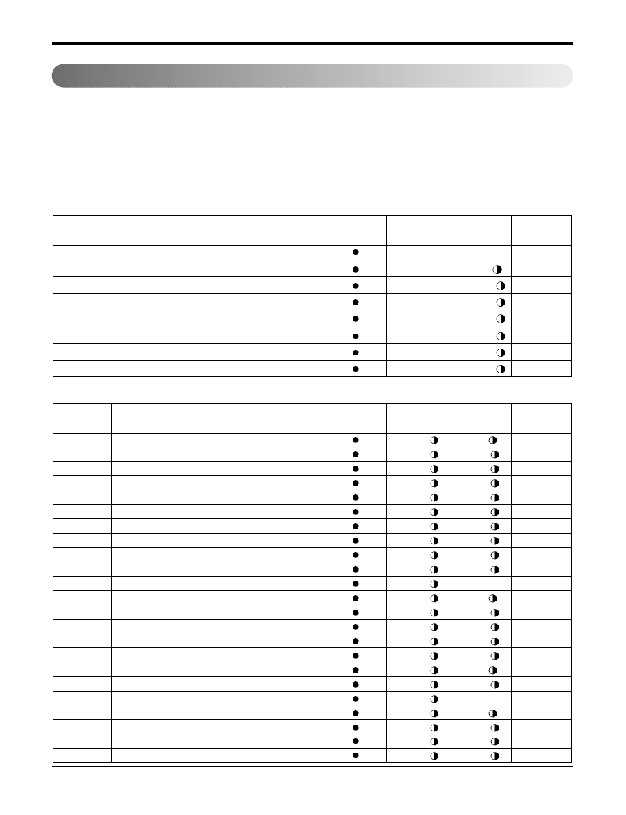
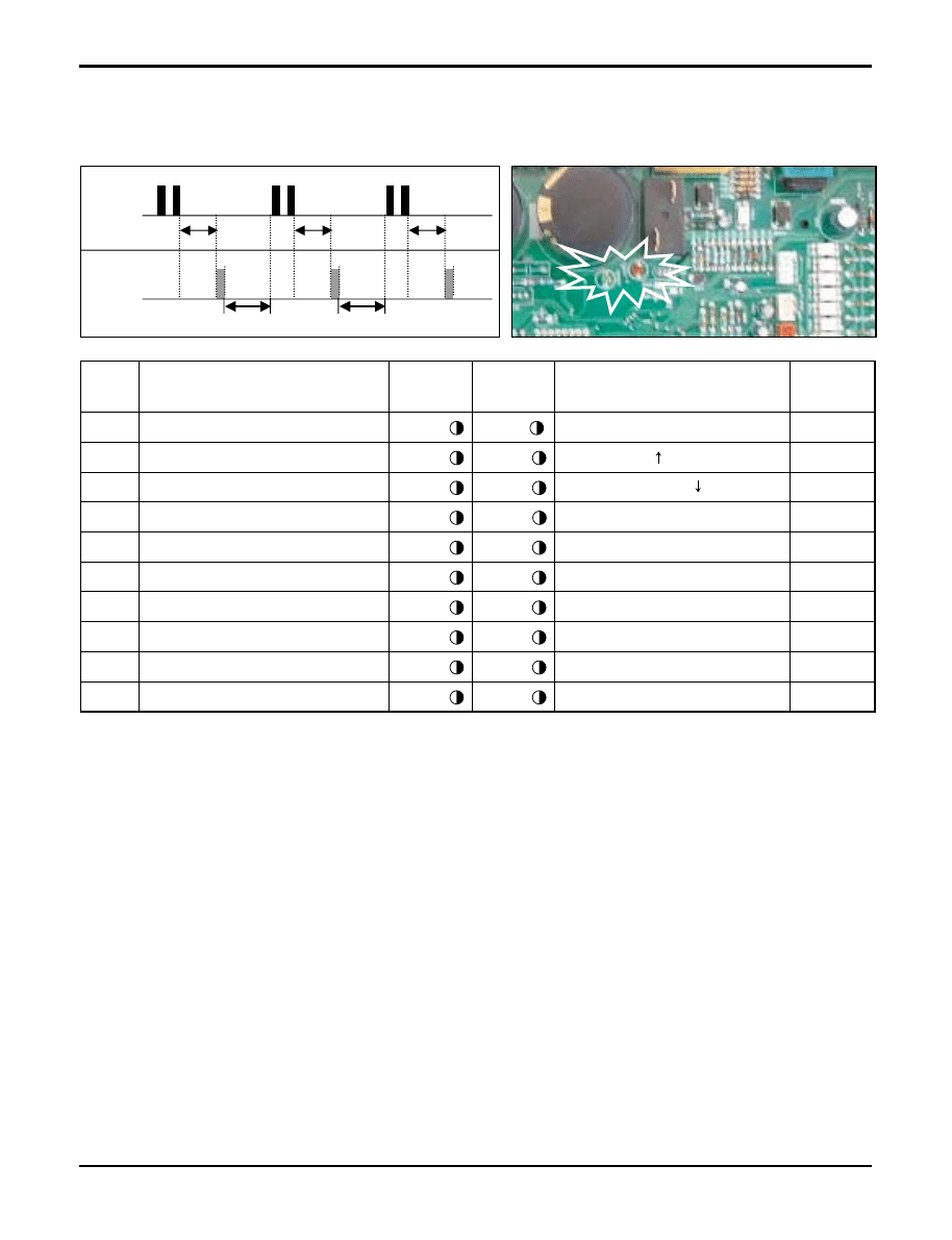
Error Indicator
• The function is to self-diagnoisis airconditioner and express the troubles identifically if there is any trouble.
• Error mark is ON/OFF for the operation LED of evaporator body in the same manner as the following table.
• If more than two troubles occur simultaneously, primarily the highest trouble fo error code is expressed.
• After error occurrence, if error is released, error LED is also released simultaneously.
• To operate again on the occurrence of error code, be sure to turn off the power and then turn on.
• Having or not of error code is different from Model.
Troubleshooting Guide
Self-diagnosis Function
Indoor Error
Error code
Description
INV TPS
LED 1
(Red)
LED 2
(Green)
Indoor
Status
00
No Error
ON
01
Indoor Room themistor error
1time
OFF
02
Indoor in-piping sensor error
2times
OFF
03
Remote controller error
3times
OFF
04
Drain Pump error
4times
OFF
05
Communcation error between in and out
5times
OFF
06
Indoor Out-Piping sensor error
6times
OFF
07
Differnt mode operation
7times
OFF
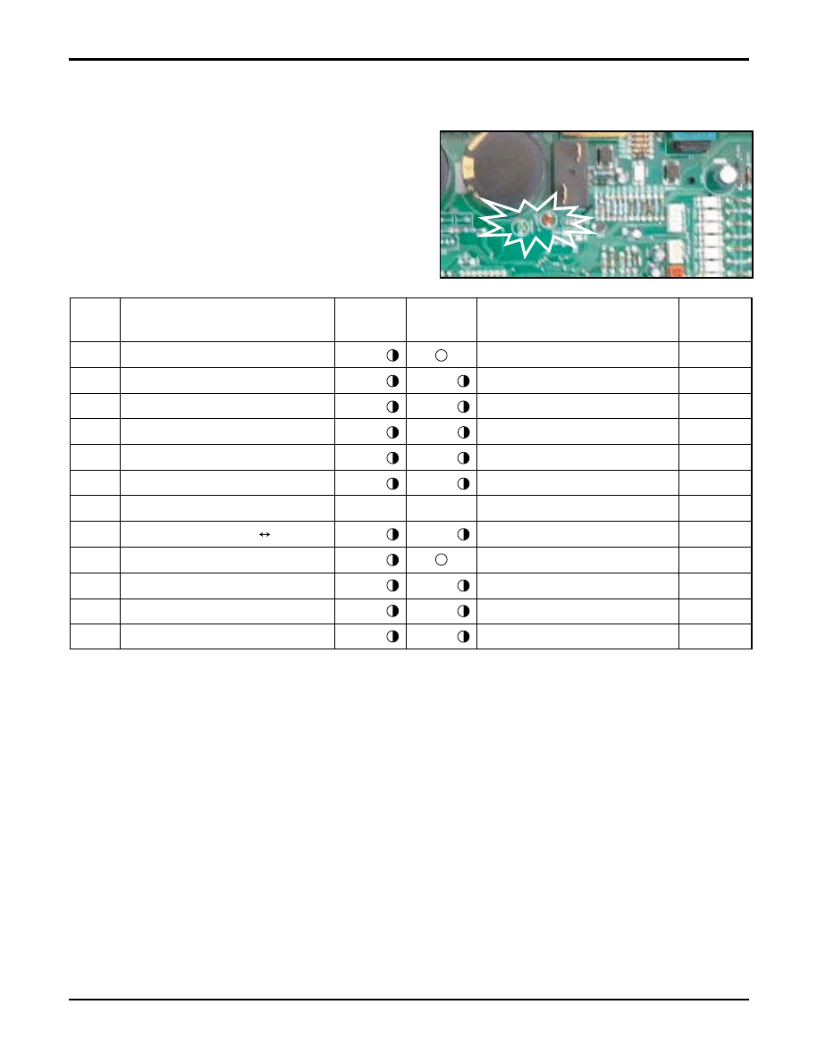
Outdoor Error
Error Code
Description
INV TPS
LED 1
(Red)
LED 2
(Green)
Indoor
Status
21
DC Peak (IPM Fault)
2times
1time
OFF
22
CT 2(Max CT)
2times
2times
OFF
23
DC Link Low Volt.
2times
3times
OFF
24
L_P/Heater Sink
2times
4times
OFF
25
Low voltage / Over voltage
2times
5times
OFF
26
DC Comp Position Error
2times
6times
OFF
27
PSC Fault Error
2times
7times
OFF
28
DC Link High Volt
2times
8times
OFF
32
D-Pipe High (INV)
3times
2times
OFF
33
D-Pipe High (Normal)
3times
3times
OFF
40
CT Sensor (Open/Short)
4times
O
OFF
41
INV. D-PipeTh Error(Open/Short)
4times
1time
OFF
44
Outdoor air Th Error(Open/Short)
4times
4times
OFF
45
Cond. Pipe Th Error(Open/Short)
4times
5times
OFF
46
Suction Pipe Error(Open/Short)
4times
6times
OFF
47
Const D-pipe Th Error(Open/Short)
4times
7times
OFF
51
Capacity over
5times
1time
OFF
53
Signal error (Indoor
↔
Outdoor)
5times
3times
OFF
60
EEPROM Check Sum Error
6times
O
OFF
61
Cond. Pipe High
6times
1time
OFF
62
Heatsink High
6times
2times
OFF
63
Cond. Pipe Low
6times
3times
OFF
65
Heatsoml Th error (Open/Short)
6times
5times
OFF
172 Multi type Air Conditioner
Troubleshooting Guide
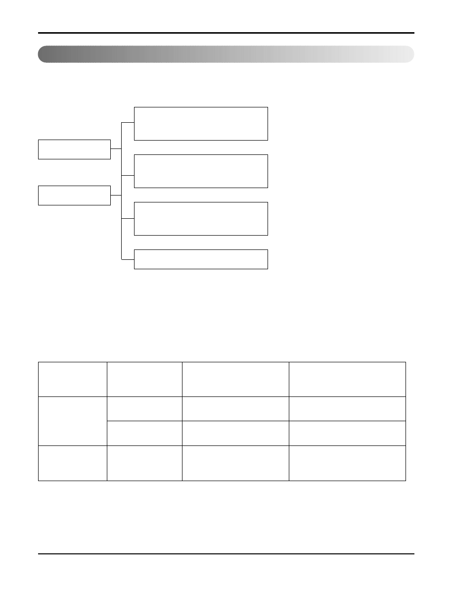
Trouble analysis
1. Check temperature difference between intake and discharge air, and operating current.
All amount of refrigerant leaked out.
Check refrigeration cycle.
Refrigerant leakage
Clog of refrigeration cycle
Defective compressor
Excessive amount of refrigerant
Normal
Notice:
Temperature difference between intake and discharge air depends on room air humidity. When the room air
humidity is relatively higher, temperature difference is smaller. When the room air humidity is relatively lower
temperature difference is larger.
2. Check temperature and pressure of refrigeration cycle.
Notice:
1. The suction pressure is usually 4.5~6.0 kg/cm
2
G at normal condition.
2. The temperature can be measured by attaching the thermometer to the low pressure tubing and wrap it with
putty.
Temp. difference
: approx. 0°C
Current
: less than 80% of
rated current
Temp. difference
: approx. 8°C
Current
: less than 80% of
rated current
Temp. difference
: less than 8°C
Current
: near the rated
current
Temp. difference
: over 8°C
Temp. Difference
Operating Current
Suction pressure
Temperature
(Compared with
(Compared with
Cause of Trouble
Description
the normal value)
the normal value)
High
Defective compressor
Current is low.
Normal
Excessive amount of
High pressure does not quickly
refrigerant
rise at the beginning of operation.
Insufficient amount of
Current is low.
Lower
Higher
refrigerant(Leakage)
Clogging
Higher
Cycle Troubleshooting Guide
Service Manual 173
Troubleshooting Guide
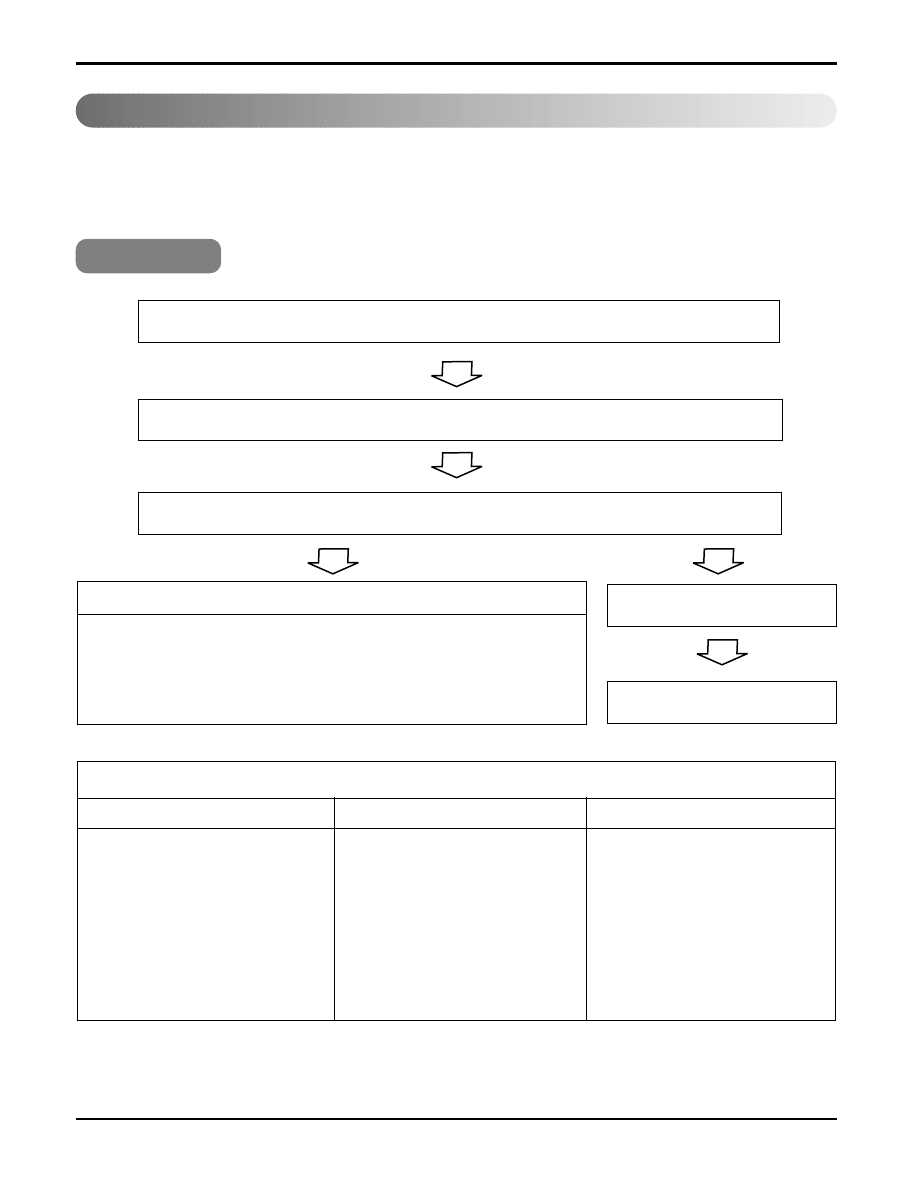
Electronic Parts Troubleshooting Guide
❇
Refer to electronic contorol device drawing & schematic diagram.
1. A2UW146FA0/1/2, A2UW166FA0/1, A2UW186FA0, A3UW186FA0/1
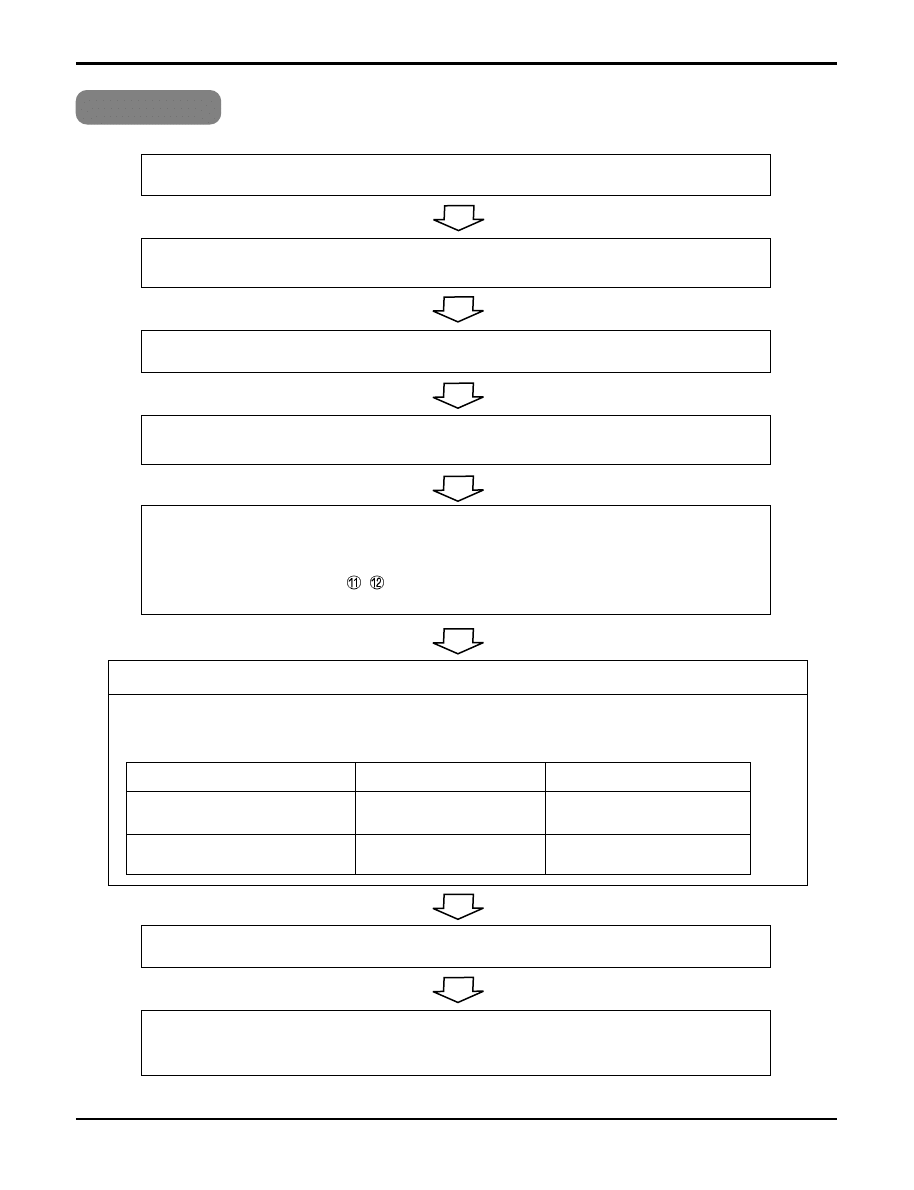
The Product doesn’t operate at all.
Turn off the main power and wait until LED on outdoor PCB is off.
Turn on the main power again.
Does "Beeping" sound is made from the indoor unit?
• Primarily, the operating condi-
tion of Micom is O.K.
• Check CN-DISP1
Check the voltage of power(AC220V/AC240V, 50Hz).
• The voltage of main power.
• The voltage applied to the unit.
• The connecting method of Indoor/Outdoor connecting cable (each color)
• The P.W.B. Ass'y
(Fuse, Noise Filter, Power Transformer, IC01D, IC02D, etc.)
Trouble 1
NO
YES
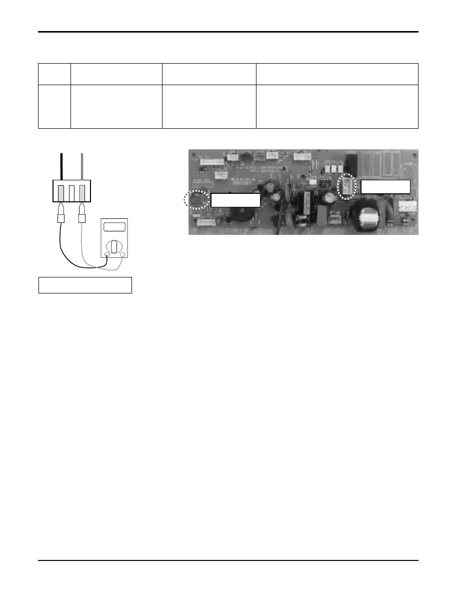
The operation check of the P.C.B. Ass'y
Procedure
1) The input voltage of power trans-
former.
2) The output voltage of power
transformer.
3) IC01D(7812)
4) IC02D(7805)
5) IC01A(KIA7036)
Specification
1) AC230V ± 30V
: Check the rated voltage
2) 14V ± 3V
3) DC12V
4) DC5V
5) The voltage of micom pin 29
: DC4.5V
↑
Remedy
1) Replace
power transfomer.
2) Replace
power transfomer.
3) Replace IC01D.
4) Replace IC02D.
5) Replace IC01A.
174 Multi type Air Conditioner
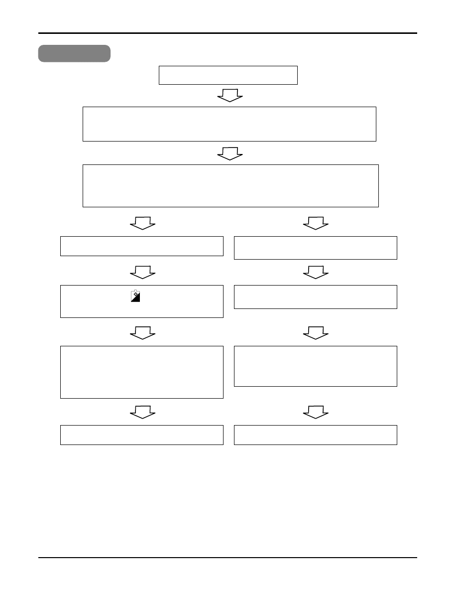
Troubleshooting Guide
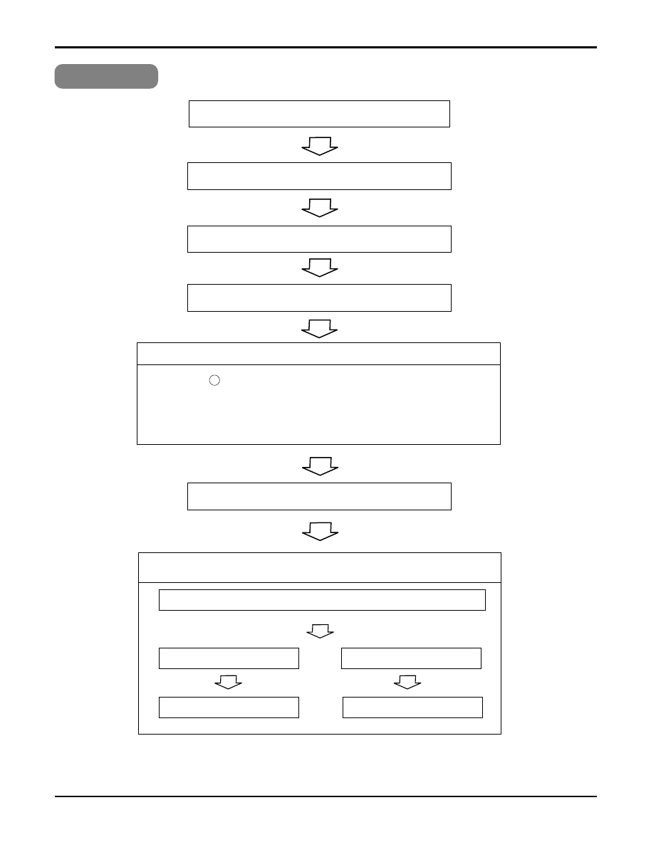
Turn on main power.
While the compressor has been stopped, the compressor does not operate
owing to the delaying function for 3 minutes after stopped.
When the compressor stopped Indoor Fan is driven by a low speed.
At this point the wind speed is not controlled by the remote controller.
(When operated in the Sleeping Mode, the wind speed is set to the low speed as force.)
Caused by the remote controller.
Caused by other parts except
the remote controller
When the mark ( ) is displayed in LCD
screen, replace battery.
Check the contact of CN-DISP 1 connector
When the detect switch (double key) inside the
remote controller door is fault, it is impossible to
operate temperature regulating(
▲
/
▼
) and wind
speed selecting.
Check DISP PWB Ass'y
-Voltage between CN1
➀
-
➆
: DC +5V
Check the Display PWB Ass'y
• Check receiver ass'y
Product doesn't operate with the remote controller.
Trouble 2
Service Manual 175
Troubleshooting Guide
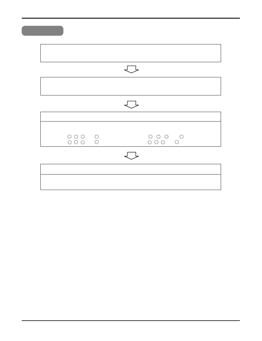
Turn on the main power.
When in air circulation mode, compressor/outdoor fan is stopped.
Turn off main power.
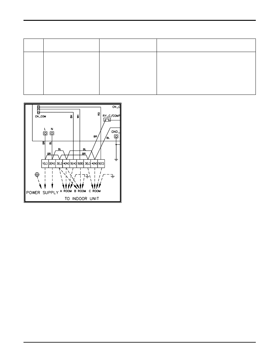
Check the electrical wiring diagram of Outdoor side.
Check the open or short of connecting wires between Indoor and Outdoor.
Check the sensor for Indoor temperature is attatched as close as to be effected by the
themperature of Heat Exchange (EVA.)
When the sensor circuit for Indoor temperature and connector are in bad connection or are
not engaged, Compressor/Outdoor fan is stopped.
• Check the related circuit of R02H(12.1K), R01H(1K), R04H(6.2K), R03H(1K), C01H(102),
C02H(102), Micom(pin No.
,
).
• Check the Indoor temperature sensor is disconnected or not (about 10K at 25°C).
Check the Relay(RY-PWR, RY-START) for driving Compressor.
• Check the voltage between brown and blue cable of terminal to connect the Outdoor
(About AC220V / 240V).
• Check the related circuit of relay in Outdoor PCB Ass'y.
Operate Cooling Mode by setting the disired temperature of the remote controller is less
than one of the Indoor temperature by 1°C at least.
The Compressor/Outdoor Fan are don't operate
Trouble 3
Check Point
Between Micom(No. 19) and
GND
DC 5V
DC 0V
DC 12V
DC 1V
↓
Between IC01M(No. 10) and
GND
Comp. ON
Comp. OFF
176 Multi type Air Conditioner
Troubleshooting Guide
When indoor Fan does not operate.
Trouble 4
Check the SSR high speed operation by remote control.
(the Indoor Fan Motor is connected)
Turn off main power.
Check the connection of CN-FAN.
Check the Fan Motor.
Check the Fuse(AC250V, T2A).
Turn on the main power
Check the related circuit of indoor Fan Motor.
• The pin No.
38
of micom and the part for driving SSR.(Q01M)
• Check the related pattern.
• Check the SSR.
- SSR Open: Indoor Fan Motor never operate.
- SSR short: Indoor Fan Motor always operates in case of ON or OFF.
The voltage of Pin No 1(orange) and 3(black) of CN-FAN.
About AC 160V over
About AC 50V over
SSR is not damaged
Check SSR
Service Manual 177
Troubleshooting Guide
• Confirm that the vertical louver is normally geared with the shaft of Stepping Motor.
• If the regular torque is detected when rotating the vertical louver with hands
⇒
Normal
• Check the connecting condition of CN-U/D or CN0L/R Connector
• Check the soldering condition(on PCB) of CN-U/D or CN0L/R Connector
Check the operating circuit of the vertical louver
• Confirm that there is DC +12V between pin
➀
of CN-U/D, CN0L/R and GND.
• Confirm that there is a soldering short at following terminals.
- Between
1
,
2
,
3
and
4
of MICOM
- Between
17
,
18
,
19
and
20
of MICOM
- Between
4
,
5
,
6
and
7
of IC01M
- Between
5
,
6
,
7
and
8
of IC01M
When the louver does not operate.
Trouble 5
If there are no problems after above checks.
• Confirm the assembly condition that are catching and interfering parts in the link of the
vertical louver
178 Multi type Air Conditioner
Troubleshooting Guide
General Information
■
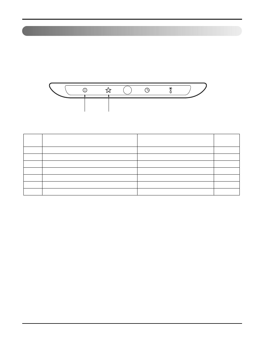
Error Indicator (Indoor)
• The function is to self-diagnosis air conditioner and express the troubles if there is any trouble.
• Error mark is displayed on display window of indoor units and wired-remote controller, and LED of outdoor unit
control board.
• If more than two troubles occur simultaneously, lower number of error code is first displayed.
• After error occurs, if error is released, error LED is also released simultaneously.
■
Indoor Error
1 digit
10 digit
Case of error
Contents
Error
code
Open / Short
Outlet pipe sensor
06
Different operation mode
Different operation mode
07
Communication Poorly
Float switch Open
Communication Poorly
Open / Short
Open / Short
Air sensor (open/short)
01
Inlet pipe sensor
02
Communication(Indoor
↔
Wired R/Control)
03
Drain pump/ Float switch
04
Communication(Indoor
↔
Outdoor)
05
Off
Off
Off
Off
Off
Off
Off
Indoor
Status
Service Manual 179
Troubleshooting Guide
■
Error Indicator (Outdoor)
Outdoor Error
Ex) Error 21 (DC Peack)
1 Time
1 Time
1 Time
2 Times
2 Times
2 Times
1 Sec.
2 Sec.
2 Sec.
1 Sec.
1 Sec.
LED01G
(RED)
LED02G
(GREEN)
Case of error
LED02G
(Green)
LED01G
(Red)
Contents
Error
code
Compressor malfunction,IPM Fault
Current is 14A
DC Link volt. Is 140V
Low / High press switch OPEN
Abnormal AC volt. Input.
Off
Off
Off
IPM Fault (Compressor Over current)
CT 2(Max. Current)
DC Link Low Volt.
Low / High press
AC Low / AC High Volt.
DC Compressor Position
PSC Fault
DC Link High Volt
Discharge Pipe Temp. High (INV)
Discharge Pipe Temp. High (Cons.)
21
22
23
24
25
26
27
28
32
33
Off
Off
Off
Off
Off
Off
Off
Off
Off
Off
Outdoor
Status
2 times
2 times
2 times
2 times
2 times
2 times
2 times
2 times
3 times
3 times
1 time
2 times
3 times
4 times
5 times
6 times
7 times
8 times
2 times
3 times
180 Multi type Air Conditioner
Troubleshooting Guide
■
Error Indicator (Outdoor)
Outdoor Error
Case of error
LED02G
(Green)
LED01G
(Red)
Contents
Error
code
CT Circuit malfunction
Open / Short
Open / Short
Open / Short
Open / Short
Open / Short
Over combination
Communication Poorly
Check sum mismatching
Cond. Temp. high
Heat sink temp. high
Open / Short
CT Circuit
D-pipe sensor INV. (open/ short)
Air sensor (open/ short)
Cond. Pipe sensor (open/ short)
Suction pipe sensor (open/ short)
D-pipe sensor Cons. (open/ short)
Over capacity
Communication (Indoor
Outdoor)
EEPROM check sum
Cond. Pipe sensor temp. high
Heat sink sensor temp. high
Heat sink sensor (open/ short)
40
41
44
45
46
47
51
53
60
61
62
65
Off
Off
Off
Off
Off
Off
Off
Off
Off
Off
Off
Off
Outdoor
Status
4 times
4 times
4 times
4 times
4 times
4 times
5 times
5 times
6 times
6 times
6 times
6 times
1 time
4 times
5 times
6 times
7 times
1 times
3 times
1 time
2 times
5 times
Service Manual 181
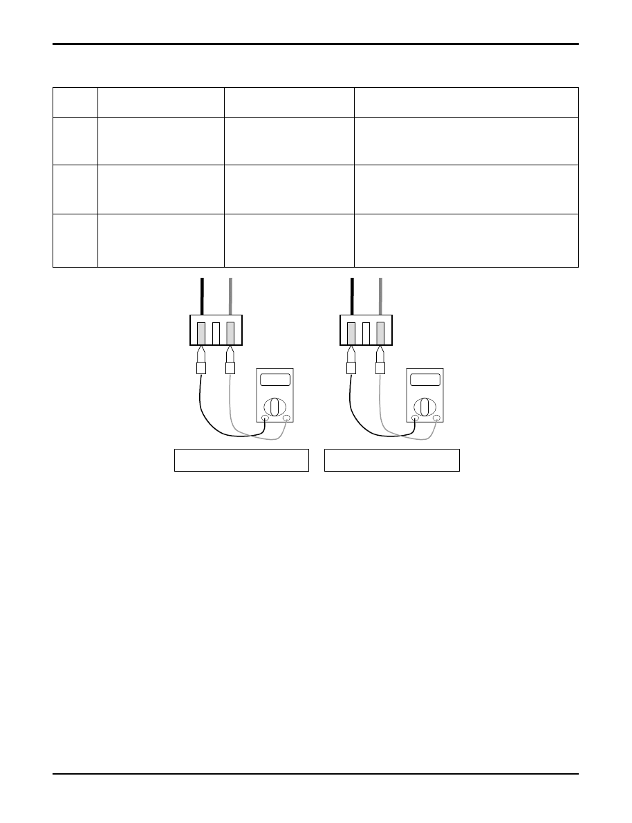
Troubleshooting Guide
1) Troubleshooting CH01, CH02, CH06
Ω
10k
Ω
Check the resistance
Check the voltage
V
2.5Vdc
01
02
06
Indoor air sensor
Indoor inlet pipe sensor
Indoor outlet pipe sensor
• Open / Short
• Soldered poorly
• Internal circuit error
• Open / Short
• Soldered poorly
• Internal circuit error
• Open / Short
• Soldered poorly
• Internal circuit error
Normal resistor : 10K
Ω
/ at 25°C (Unplugged)
Normal voltage : 2.5Vdc / at 25°C (plugged)
Normal resistor : 5K
Ω
/ at 25°C (Unplugged)
Normal voltage : 2.5Vdc / at 25°C (plugged)
Normal resistor : 5K
Ω
/ at 25°C (Unplugged)
Normal voltage : 2.5Vdc / at 25°C (plugged)
Display
code
Title
Cause of error
Check point & Normal condition
Check Point
1. Unplug the sensor on Indoor unit PCB.
2. Estimate the resistance of each sensor.
3. If the resistance of the sensor is 10K
Ω
/ 5K
Ω
at 25°C, then sensor is normal.
4. If the resistance of the sensor is 0 K
Ω
or
∞
, then sensor is abnormal.
→
Change the sensor.
5. Plug the sensor on Indoor unit PCB and Power ON.
6. Estimate the voltage of each sensor.
7. If the voltage of the sensor is 2.5Vdc at 25°C, then sensor is normal.
8. If the resistance of the sensor is 0 or 5Vdc, then sensor is abnormal.
→
Repair or Change the PCB.
182 Multi type Air Conditioner
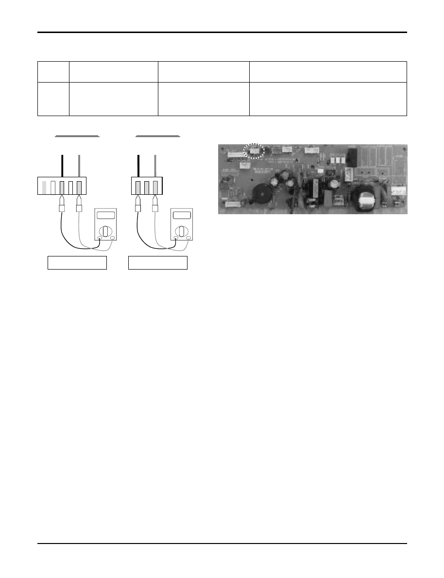
Troubleshooting Guide
2) Troubleshooting CH03
Check the Volt.
Indoor Unit
V
12Vdc
12V
S
GND
Check the Volt.
Wired R/C
V
12Vdc
12V
S
GND
CN-REMO
03
Communication
Wired R/C
• Open / Short
• Wrong connection
• Connection of wire
• Main PCB Volt. DC12V
• Noise interference
Display
code
Title
Cause of error
Check point & Normal condition
Check Point
1. Check the wire connection. (Open / Short)
→
Repair the connection
2. Check the soldering state of connector. (Soldered poorly)
→
Repair or Change the PCB.
3. Check the volt. Of main PCB power source. (DC 12V, DC 5V)
→
Repair or Change the main PCB.
4. Check the installation of wired remote controller. (Noise interference)
→
Adjust the state of installation
Service Manual 183
Troubleshooting Guide
3) Troubleshooting CH04
Check the resistance
Ω
0
Ω
CN Float
CN-Float
CN-D/PUMP
04
Drain pump
/ Float switch
• Float switch Open.
(Normal : short)
• The connection of wire(Drain pump/ Float switch)
• Drain pump power input. (220V)
• Drain tube installation.
• Indoor unit installation. (Inclination)
Display
code
Title
Cause of error
Check point & Normal condition
Check Point
1. Check the wire connection. (Open, Soldered poorly)
→
Repair the connection or change the PCB.
2. Check the resistance of float switch (Abnormal : Open, Normal : short)
→
Check the float switch.
3. Check the level of water
4. Check the volt. Of Drain pump power supply. (AC 230V)
→
Repair or Change the main PCB.
184 Multi type Air Conditioner
4) Troubleshooting CH05, CH53
04
/
53
Communication
(Indoor
→
Outdoor)
• Communication poorly
• Power input AC 220V. (Outdoor, Indoor)
• The connector for transmission is disconnected.
• The connecting wires are misconnected.
• The GND1,2 is not connected at main GND.
• The communication line is shorted at GND.
• Transmission circuit of outdoor PCB is abnormal.
• Transmission circuit of indoor PCB is abnormal.
Display
code
Title
Cause of error
Check point & Normal condition
Check Point
1. Check the input power AC230V. (Outdoor, Indoor unit)
2. Check the communication wires are correctly connected.
→
Adjust the connection of wire
→
Confirm the wire of “Live”, “Neutral”
3. Check the resistance between communication line and
GND. (Normal : Over 2M
Ω
)
4. Check the connector for communication is correctly
connected.
5. Check the connection of GND1, GND2, and main GND.
6. If one indoor unit is operated normally, outdoor PCB is no
problem.
→
Check the another indoor unit.
* CH05 is displayed at indoor unit, CH53 is displayed at out-
door unit.
Troubleshooting Guide
Service Manual 185
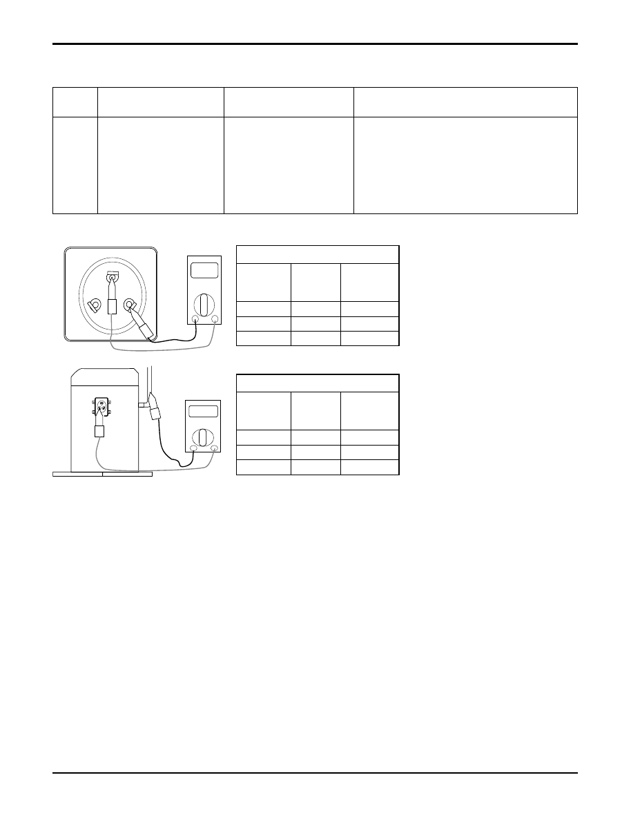
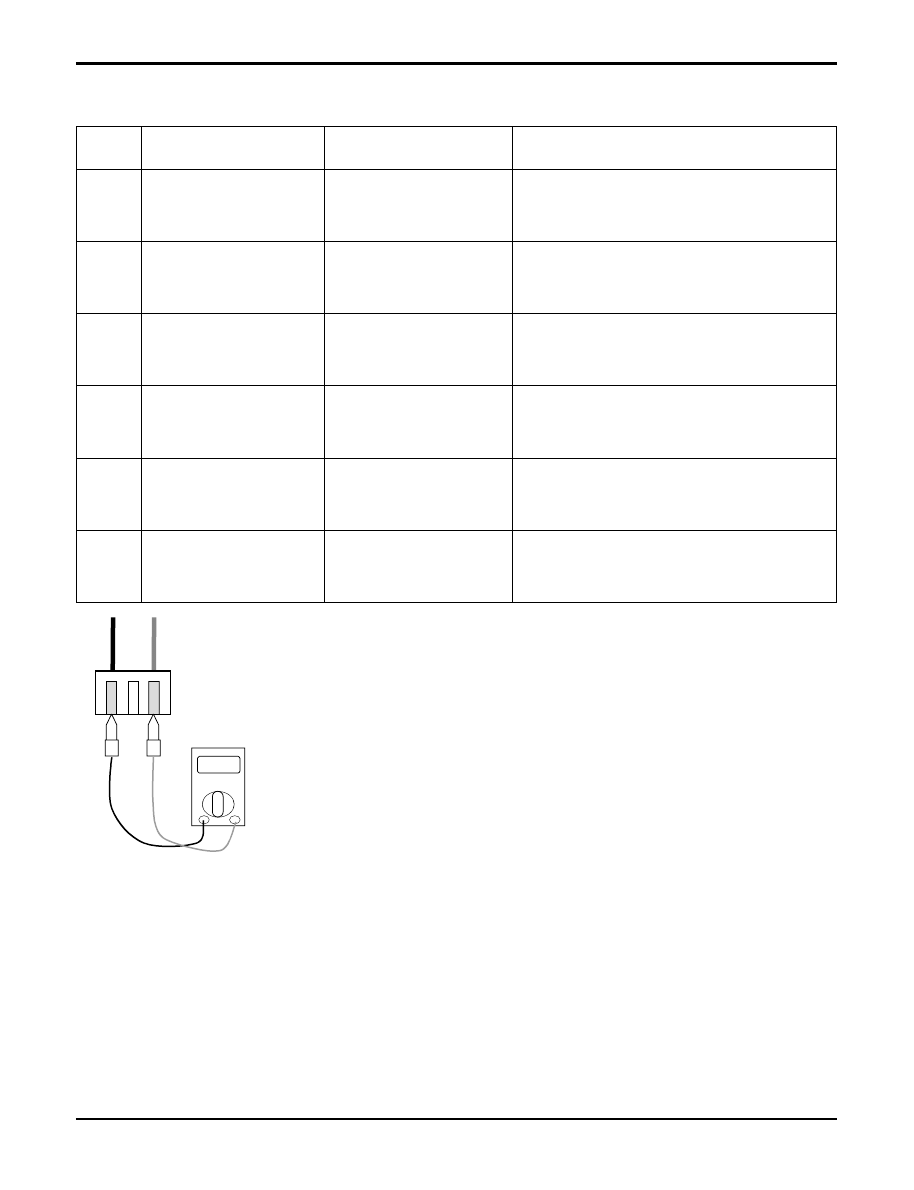
5) Troubleshooting CH21
Ω
Comp
Copper
pipe
Resistance(
Ω
) at 20°C
Resistance(
Ω
) at 20
°
C
0.64
0.64
0.64
Inverter
comp.
V-W
W-U
U-V
Terminal
0.8
0.8
0.8
Constant
comp.
2M
Ω
2M
Ω
2M
Ω
Inverter
comp.
V-GND
W-GND
U-GND
Terminal
2M
Ω
2M
Ω
2M
Ω
Constant
comp.
V
U
W
Ω
Comp
21
DC Peak
• Instant over current
• Over Rated current
• Poor insulation of IPM
• An instant over current in the U,V,W phase
- Comp lock
- The abnormal connection of U,V,W
• Over load condition
- Overcharging of refrigerant
- Pipe length.
• Poor insulation of compressor
Display
code
Title
Cause of error
Check point & Normal condition
Check Point
1. Check the wire connection. (U,V,W)
2. Check the load condition. (Refrigerant, Pipe length, …)
→
Adjust the load condition
3. Check the electricity leakage of the compressor.
→
Normal : Over 2M
Ω
.
4. Check the resistance of compressor.
→
Normal : 0.65
Ω
(INV), 0.8
Ω
(Cons.)
→
No difference at each terminal.
5. Check the insulation from water at IPM part.
→
Check the trace of water.
6. Check the IPM circuit.
Troubleshooting Guide
186 Multi type Air Conditioner
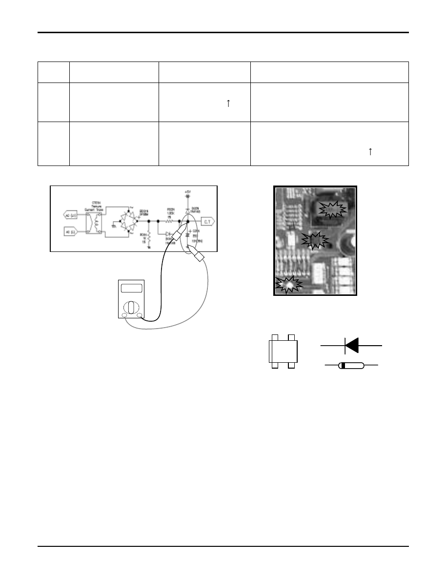
6) Troubleshooting CH22
V
+
-
+
-
+
-
21
22
Max. C/T
C/T
Internal circuit
Over current (14A
)
Initial current error
Malfunction of compressor
Blocking of pipe
Low voltage input
Refrigerant, pipe length, blocked, …
Malfunction of current detection circuit.
(Open / Short)
The voltage of “C01N” Is 4.0Vdc(25A)
.
Display
code
Title
Cause of error
Check point & Normal condition
Check Point
1. Check the power source.
2. Check the fan operation is right.
3. Check the current.
4. Check the install condition.
5. Check the internal circuit. (C/T, Diode, Resistor)
Troubleshooting Guide
Service Manual 187
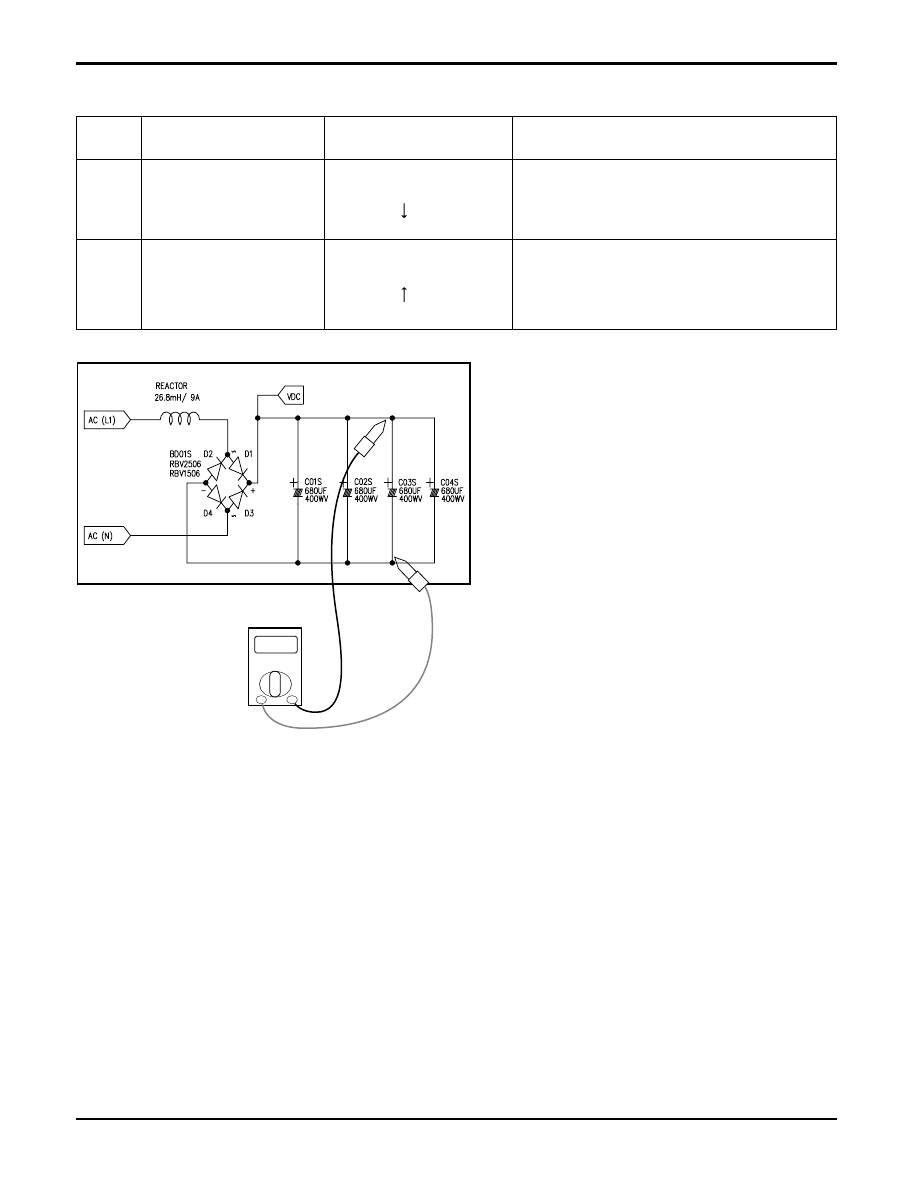
7) Troubleshooting CH23, CH28
V
23
28
DC Link
Low voltage.
DC Link
High voltage
• DC link volt. is
140Vdc
.
• DC link volt. is
420Vdc
.
• Check the power source.
• Check the components.
• Check the power source.
• Check the components.
Display
code
Title
Cause of error
Check point & Normal condition
Check Point
1. Check the power source.
2. Check the components
(B/Diode, Reactor, PSC Parts )
Troubleshooting Guide
188 Multi type Air Conditioner
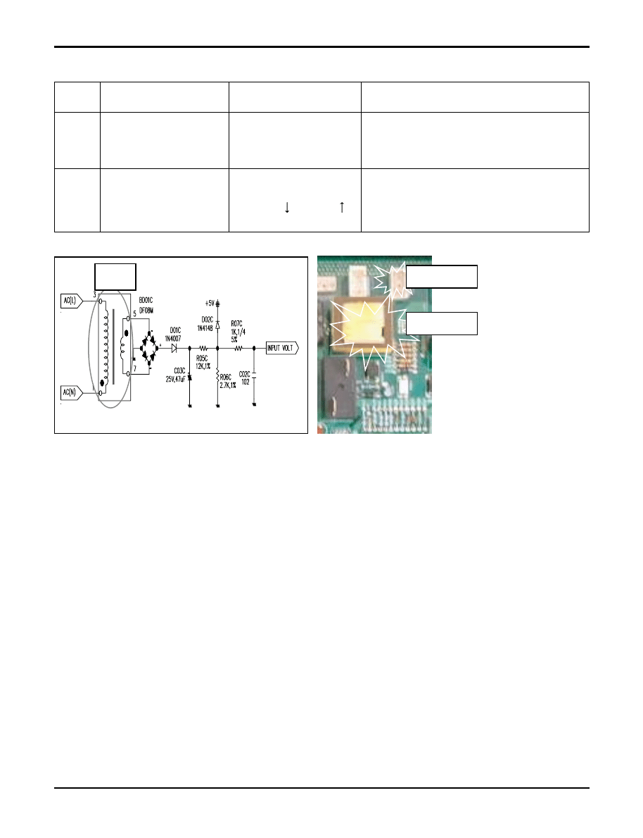
8) Troubleshooting CH24, CH25
CN TRNAS1
CN PRESS
TRANS1
50Hz, DC12V
24
25
Press S/W Open
Input voltage
• Low / High press
S/W open.
• Abnormal Input voltage
(140Vac
, 300Vac
.
• Check the connection of “CN_Press”.
• Check the components.
• Check the power source.
• Check the components.
Display
code
Title
Cause of error
Check point & Normal condition
Check Point
• CH 24
1. Check the connection of “CN_PRESS”
2. Check the install condition for over load.
3. Check the SVC V/V open.
4. Check the leakage of refrigerant.
• CH 25
1. Check the power source.
2. Check the components
(Trans1, B/Diode, Diode, Resistance)
Troubleshooting Guide
Service Manual 189
Troubleshooting Guide
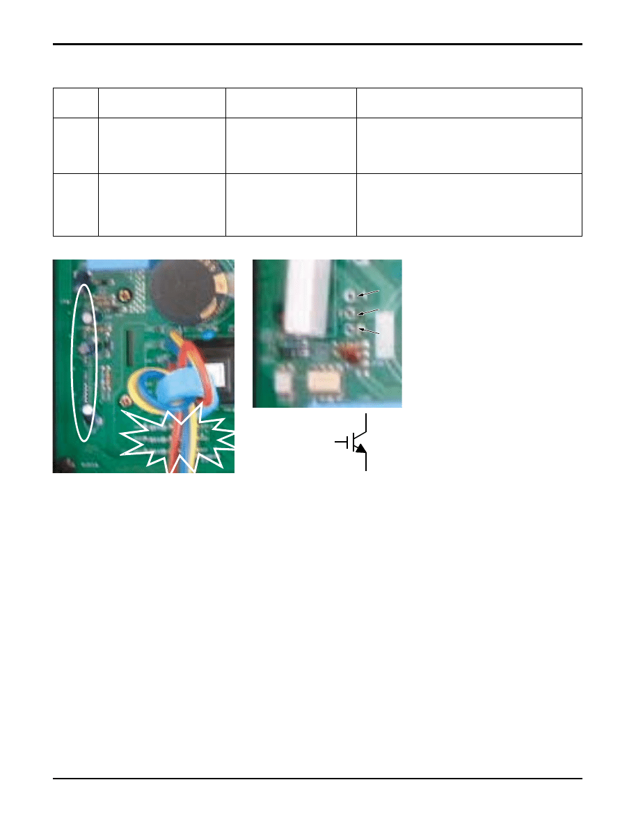
9) Troubleshooting CH26, CH27
E
C
B
E
C
B
E
C
B
26
27
DC Compressor
Position
PSC Fault
• Compressor
position detect error
• Over current at “IGBT”
• Check the connection of comp wire “U,V,W”
• Malfunction of compressor
• Check the component of “IPM”, detection parts.
• Check the component of “IGBT” .
• Check the components.
Display
code
Title
Cause of error
Check point & Normal condition
Check Point
• CH 26
1. Check the connection of “U,V,W”
2. Check the insulation of IPM part.
3. Check the compressor. (same with CH21)
• CH 27
1. Check the component of “IGBT”
2. Check the components
(IGBT, R04S, NF1, BD02S)
190 Multi type Air Conditioner
Troubleshooting Guide
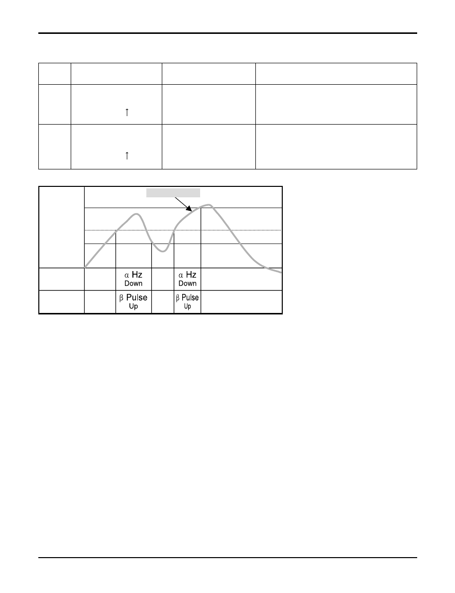
10) Troubleshooting CH32, CH33
LEV Openness
(Pulse)
COMP Frequency
(Hz)
Toff(105)
°
C
T1(90)
°
C
T2(95)
°
C
OFF
Normal
OFF Control
Normal
Normal
Normal
D-Pipe temp.
32
33
D-pipe (Inverter)
temp. high
(105°C
)
D-pipe (Constant)
temp. high
(105°C
)
• Discharge sensor
(Inverter) temp. high
• Discharge sensor
(Cons.) temp. high
• Check the discharge pipe sensor for INV.
• Check the install condition for over load.
• Check the leakage of refrigerant.
• Check the SVC V/V open.
• Check the discharge pipe sensor for Cons.
• Check the install condition for over load.
• Check the leakage of refrigerant.
• Check the SVC V/V open.
Display
code
Title
Cause of error
Check point & Normal condition
Check Point
• CH 32
1. Check the install condition for over load.
2. Check the SVC V/V open.
3. Check the leakage of refrigerant.
• CH 33
1. Check the install condition for over load.
2. Check the SVC V/V open.
3. Check the leakage of refrigerant.
4. Check the constant compressor. (same with CH21)
Service Manual 191
11) Troubleshooting CH41, CH44, CH45, CH46, CH47, CH65
Ω
41
44
45
46
47
65
D-pipe sensor (Inverter)
Air sensor
Condenser Pipe sensor
Suction Pipe sensor
D-pipe sensor (Constant)
Heat sink sensor
• Open / Short
• Soldered poorly
• Internal circuit error
• Open / Short
• Soldered poorly
• Internal circuit error
• Open / Short
• Soldered poorly
• Internal circuit error
• Open / Short
• Soldered poorly
• Internal circuit error
• Open / Short
• Soldered poorly
• Internal circuit error
• Open / Short
• Soldered poorly
• Internal circuit error
• Normal resistor : 200K
Ω
/ at 25°C (Unplugged)
• Normal voltage : 4.5Vdc / at 25°C (plugged)
• Normal resistor : 10K
Ω
/ at 25°C (Unplugged)
• Normal voltage : 2.5Vdc / at 25°C (plugged)
• Normal resistor : 5K
Ω
/ at 25°C (Unplugged)
• Normal voltage : 2.5Vdc / at 25°C (plugged)
• Normal resistor : 5K
Ω
/ at 25°C (Unplugged)
• Normal voltage : 2.5Vdc / at 25°C (plugged)
• Normal resistor : 200K
Ω
/ at 25°C (Unplugged)
• Normal voltage : 4.5Vdc / at 25°C (plugged)
• Normal resistor : 10K
Ω
/ at 25°C (Unplugged)
• Normal voltage : 2.5Vdc / at 25°C (plugged)
Display
code
Title
Cause of error
Check point & Normal condition
Check Point
1. Estimate the resistance of each sensor.(Unplugged)
2. Estimate the voltage of each sensor.(Plugged)
3. If the resistance of the sensor is 0 k
Ω
or
∞
, then sensor is abnormal.
If the voltage of the sensor is 0 V or 5Vdc, then sensor is abnormal.
Troubleshooting Guide
192 Multi type Air Conditioner
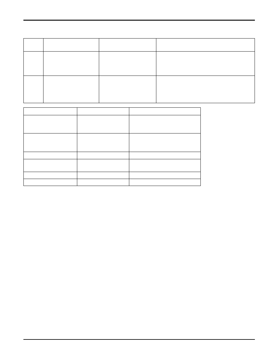
12) Troubleshooting CH51, CH60
51
60
Over capacity
EEPROM
Check sum
• Over capacity
Combination
• Check sum error
• Check the indoor unit capacity.
• Check the combination table.
• Check the PCB ASM P/No.
• Check the poor soldering.
Display
code
Title
Cause of error
Check point & Normal condition
Check Point
• CH 51
1. Check the indoor unit capacity.
• CH 60
1. Check the insertion condition of EEPROM.
2. Check the poor soldering
Troubleshooting Guide
Model
Gross max. capacity
Max. single indoor unit capacity
A2UW146FA0
A2UW146FA1
21k
12k
A2UW146FA2
A2UW166FA0
A2UW166FA1
24k
12K
A2UW186FA0
A3UW186FA0
30k
12k
A3UW246FA0
33k
18K
A4UW246FA0
A4UW306FA0
39k
18K
A6UW406FA0
52k
24K
Service Manual 193
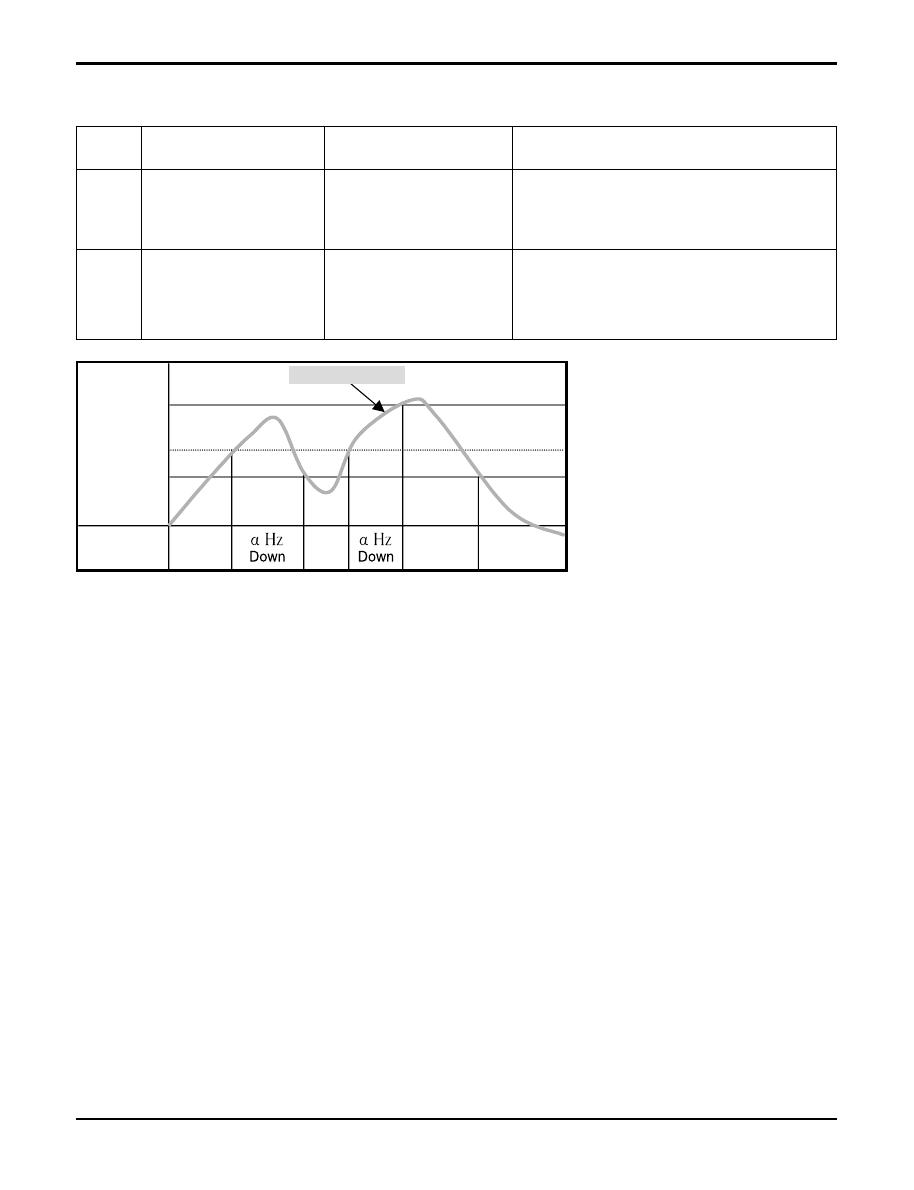
13) Troubleshooting CH61, CH62
61
62
Condenser
pipe sensor
temp. high
Heat sink sensor
temp. high
• Condenser pipe sensor
detected high
temp.(65°C)
• Heat sink sensor
detected high
temp.(85°C)
• Check the load condition.
• Check the sensor of Condenser pipe sensor.
• Check the fan is locked.
• Check the sensor of heat sink.
Display
code
Title
Cause of error
Check point & Normal condition
Check Point
• CH 61
1. Check the install condition for over load.
(Refrigerant, Pipe length, Blocked, …)
• CH 62
1. Check the fan is locked.
2. Check the Outdoor temp. is very high.
COMP Frequency
(Hz)
Toff
°
C
T1
°
C
T2
°
C
OFF
Normal
Normal
Normal
Heat Sink temp.
Troubleshooting Guide
Wyszukiwarka
Podobne podstrony:
liczba gorotworu L i Lg id 2678 Nieznany
BLEDY LOGICZNE id 75111 Nieznany (2)
bledy i statystyka id 90029 Nieznany
bledy 3 id 90025 Nieznany (2)
5 Bledy termoelektr MEP id 4005 Nieznany
4 Bledy instalacyjne MEP id 375 Nieznany
LG falowniki i filtry id 267643 Nieznany
bledy id 75132 Nieznany (2)
bledy 3 id 90025 Nieznany (2)
5 Bledy termoelektr MEP id 4005 Nieznany
Abolicja podatkowa id 50334 Nieznany (2)
4 LIDER MENEDZER id 37733 Nieznany (2)
katechezy MB id 233498 Nieznany
metro sciaga id 296943 Nieznany
perf id 354744 Nieznany
interbase id 92028 Nieznany
Mbaku id 289860 Nieznany
Probiotyki antybiotyki id 66316 Nieznany
miedziowanie cz 2 id 113259 Nieznany
więcej podobnych podstron