
. . . . . . . . . . . . . . . . . . . . . . . . . . . . . . . . . . . . .
Notice
The information in this guide is subject to change without notice.
COMPAQ COMPUTER CORPORATION SHALL NOT BE LIABLE FOR
TECHNICAL OR EDITORIAL ERRORS OR OMISSIONS CONTAINED HEREIN;
NOR FOR INCIDENTAL OR CONSEQUENTIAL DAMAGES RESULTING FROM
THE FURNISHING, PERFORMANCE, OR USE OF THIS MATERIAL.
This guide contains information protected by copyright. No part of this guide may be
photocopied or reproduced in any form without prior written consent from Compaq
Computer Corporation.
1997 Compaq Computer Corporation.
All rights reserved. Printed in the U.S.A.
Compaq and LTE are registered in the U. S. Patent and Trademark Office.
Armada is a trademark of Compaq Computer Corporation.
Microsoft, MS-DOS, and Windows are registered trademarks of Microsoft Corporation.
The software described in this guide is furnished under a license agreement or
nondisclosure agreement. The software may be used or copied only in accordance with
the terms of the agreement.
Product names mentioned herein may be trademarks and/or registered trademarks of their
respective companies.
Maintenance and Service Guide
Compaq
ArmadaStation
Compaq
Armada MiniStation E
Compaq
Armada MiniStation EX
Compaq Armada 7000 Family of Personal Computers
First Edition August 1997
Documentation Part Number 272412-001
Spare Part Number 296391-001
Compaq Computer Corporation

. . . . . . . . . . . . . . . . . . . . . . . . . . . . . . . . . . . . .
Contents
v
Contents
Preface
Symbols.............................................................................................................. ix
Technician Notes ............................................................................................... ix
Serial Number ..................................................................................................... x
Locating Additional Information........................................................................ x
Chapter 1
Product Description
1.1 ArmadaStation Features............................................................................1-1
1.2 ArmadaStation Components.....................................................................1-4
Activity Lights.............................................................................................1-8
MultiBay......................................................................................................1-8
Half-Height Bay ..........................................................................................1-8
Security Lock...............................................................................................1-9
PC Card Slots ..............................................................................................1-9
Regional Modem and Ethernet Differences ..............................................1-10
PCI and ISA Expansion Boards ................................................................1-10
1.3 Armada MiniStation Features.................................................................1-11
1.4 Armada MiniStation Components ..........................................................1-13
Activity Lights...........................................................................................1-16
MultiBay....................................................................................................1-16
Security Lock.............................................................................................1-16
PC Card Slots ............................................................................................1-17
Regional Modem and Ethernet Differences ..............................................1-17
Chapter 2
Troubleshooting
Before Replacing Parts ....................................................................................2-1
Solving Docking and Undocking Problems................................................2-2
Solving Expansion Board Problems............................................................2-3
Solving Network Problems .........................................................................2-3
Chapter 3
Illustrated Parts Catalog
3.1 ArmadaStation Components.....................................................................3-2
3.2 Miscellaneous Base Plastics Kit Components..........................................3-4
3.3 Miscellaneous Base Hardware Kit Components ......................................3-5
3.4 Miscellaneous Cable Kits .........................................................................3-6
3.5 Miscellaneous Cable Kit Components .....................................................3-8
3.6 Miscellaneous ...........................................................................................3-9
3.7 Documentation..........................................................................................3-9
3.8 Armada MiniStation Components ..........................................................3-10

. . . . . . . . . . . . . . . . . . . . . . . . . . . . . . . . . . . . .
vi
Contents
3.9 Miscellaneous Enclosures Kit Components ...........................................3-12
3.10 Miscellaneous Plastics Kit Components ..............................................3-13
3.11 MultiBay/PC Card Assembly ...............................................................3-14
3.12 ArmadaStation and Armada MiniStation Options ...............................3-16
3.13 Miscellaneous .......................................................................................3-18
3.14 Documentation......................................................................................3-18
Chapter 4
Removal and Replacement Preliminaries
4.1 Electrostatic Discharge .............................................................................4-1
Generating Static .........................................................................................4-1
Preventing Electrostatic Damage to Equipment .........................................4-2
Preventing Damage to Drives .....................................................................4-2
Grounding Methods ....................................................................................4-3
Grounding Workstations .............................................................................4-3
Grounding Equipment.................................................................................4-4
Recommended Materials and Equipment ...................................................4-4
4.2 Service Considerations .............................................................................4-5
Tool and Software Requirements................................................................4-5
Screws..........................................................................................................4-5
Cables and Connectors ................................................................................4-6
Plastic Parts .................................................................................................4-6
Chapter 5
ArmadaStation Removal and Replacement Procedures
5.1 Serial Number ...........................................................................................5-1
5.2 Disassembly Sequence Chart ...................................................................5-2
5.3 Preparing the ArmadaStation for Disassembly ........................................5-3
5.4 External Components ...............................................................................5-4
Compaq Logo ..............................................................................................5-4
ArmadaStation Feet.....................................................................................5-5
Alignment Tray Assembly ..........................................................................5-6
5.5 Rear Panel Assembly................................................................................5-8
5.6 Upper Case Assembly ............................................................................5-11
5.7 Drive Cage Shield...................................................................................5-14
5.8 Half-Height Bays ....................................................................................5-16
Half-Height Drives ....................................................................................5-16
Half-Height MultiBay Adapters................................................................5-22
5.9 I/O Assembly ..........................................................................................5-31
5.10 Top Brace..............................................................................................5-35
5.11 Left Speaker Assembly.........................................................................5-38
5.12 Control Panel Cable..............................................................................5-39
5.13 Control Panel Assembly .......................................................................5-40

. . . . . . . . . . . . . . . . . . . . . . . . . . . . . . . . . . . . .
Contents
vii
5.14 Expansion Boards .................................................................................5-50
5.15 Mechanism Assembly...........................................................................5-52
5.16 Power Supply........................................................................................5-55
5.17 Backplane Assembly.............................................................................5-57
5.18 Expansion Card Cage ...........................................................................5-59
Chapter 6
Armada MiniStation Removal and Replacement Procedures
6.1 Serial Number ...........................................................................................6-1
6.2 Disassembly Sequence Chart....................................................................6-2
6.3 Preparing the Armada MiniStation for Disassembly ...............................6-3
6.4 External Components................................................................................6-4
Compaq Logo ..............................................................................................6-4
Armada MiniStation Feet ............................................................................6-5
6.5 Enclosure Cover........................................................................................6-6
6.6 Module Assembly .....................................................................................6-7
6.7 Power Supply ..........................................................................................6-11
6.9 MultiBay/PC Card Assembly .................................................................6-12
Chapter 7
Specifications
7.1 ArmadaStation Physical and Environmental Specifications....................7-1
7.2 Armada MiniStation Physical and Environmental Specifications ...........7-2
Appendix A
Connector Pin Assignments
...............................................................................A-1
Appendix B
Power Cord Set Requirements
3-Conductor Power Cord Set.......................................................................... B-1
General Requirements ................................................................................ B-1
Country-Specific Requirements ................................................................. B-2
Notes ........................................................................................................... B-2
Index
............................................................................................................................ I-1

. . . . . . . . . . . . . . . . . . . . . . . . . . . . . . . . . . . . .
Preface
Preface
ix
This Maintenance and Service Guide is a troubleshooting guide that can be used for
reference when servicing the Compaq ArmadaStation and Armada MiniStation E
and EX.
Compaq Computer Corporation reserves the right to make changes to the Compaq
ArmadaStation and Armada MiniStation E and EX without notice.
Additional information is available on the Compaq ArmadaStation and Armada
MiniStation E and EX Illustrated Parts Map. Information for the Compaq Armada 7700
Family of Personal Computers is available in the Compaq Armada 7700 Family of
Personal Computers Maintenance and Service Guide and Illustrated Parts Map.
Symbols
The following words and symbols mark special messages throughout this guide:
!
WARNING: Text set off in this manner indicates that failure to follow directions in the
warning could result in bodily harm or loss of life.
CAUTION: Text set off in this manner indicates that failure to follow directions in the
caution could result in damage to equipment or loss of information.
IMPORTANT:
Text set off in this manner presents clarifying information or specific
instructions.
NOTE:
Text set off in this manner presents commentary, sidelights, or interesting points
of information.
Technician Notes
!
WARNING: Only authorized technicians trained by Compaq should attempt to repair this
equipment. All troubleshooting and repair procedures are detailed to allow only
subassembly/module level repair. Because of the complexity of the individual boards and
subassemblies, no one should attempt to make repairs at the component level or to
make modifications to any printed wiring board. Improper repairs can create a safety
hazard. Any indication of component replacement or printed wiring board modifications
may void any warranty or exchange allowances.
!
WARNING: The computer is designed to be electrically grounded. To ensure proper
operation, plug the AC power cord into a properly grounded electrical outlet only.
CAUTION: To properly ventilate your system, you must provide at least 3 inches
(7.62 cm) of clearance on the front and back of the computer.

. . . . . . . . . . . . . . . . . . . . . . . . . . . . . . . . . . . . .
x
Preface
Serial Number
When requesting information or ordering spare parts, provide the ArmadaStation or
Armada MiniStation serial number. The ArmadaStation serial number is located on the
right side below the PCI/ISA expansion slots; the Armada MiniStation serial number is
located on the left side above the power button.
Locating Additional Information
The following documentation is available to support the ArmadaStation and Armada
MiniStation:
■ Compaq ArmadaStation documentation set
■ Compaq Armada MiniStation documentation set
■ Service training guides
■ Compaq Service Advisories and Bulletins
■ Compaq QuickFind
■ Compaq Service Quick Reference Guide
■ Compaq ArmadaStation and Armada MiniStation E and EX Maintenance and
Service Guide
■ Compaq ArmadaStation and Armada MiniStation E and EX Illustrated Parts Map
■ Compaq Armada 7700 Family of Personal Computers Maintenance and Service
Guide
■ Compaq Armada 7700 Family of Personal Computers Illustrated Parts Map

. . . . . . . . . . . . . . . . . . . . . . . . . . . . . . . . . . . . .
Chapter 1
Introduction
1-1
Product Description
1.1 ArmadaStation Features
The Compaq ArmadaStation provides fully integrated desktop capabilities for the
Compaq Armada 7000 Family of Personal Computers. The ArmadaStation eliminates
the need to disconnect external devices when you remove the computer.
Figure 1-1. Compaq ArmadaStation

. . . . . . . . . . . . . . . . . . . . . . . . . . . . . . . . . . . . .
1-2
Introduction
The ArmadaStation provides a MultiBay device bay, a half-height device bay, two
PC Card slots, integrated Ethernet, integrated stereo speakers, modem connections,
computer I/O port replication, and connections for up to two PCI or ISA expansion
boards. When the computer is docked in the ArmadaStation, the total system
functionality includes:
■ Support for up to three MultiBay devices simultaneously
■ Overall system support for up to four hard drives
*
or two diskette drives
■ Up to three CD-ROM drives installed as follows:
– Three CD-ROM drives: The two drives in the ArmadaStation must be used for
data; the CD-ROM drive in the computer can then be used for audio or data.
*
– Two CD-ROM drives: You can have one drive in the ArmadaStation and one
in the computer; either drive can be data or audio. If both drives are in the
ArmadaStation, they must be for data only.
*
– One CD-ROM drive: The drive can be either data or audio and in either the
computer or ArmadaStation.
*
■ Two PC Card slots
■ Overall system support for up to four PC cards
■ Charging of up to four battery packs
*
■ Any combination of two 32-bit PCI and 16- or 8-bit ISA expansion boards
*
An Armada 7000 Half-Height MultiBay Adapter must be installed in the
ArmadaStation to support up to four hard drives or battery packs, or three CD-ROM
drives or MultiBay devices.

. . . . . . . . . . . . . . . . . . . . . . . . . . . . . . . . . . . . .
Introduction
1-3
The ArmadaStation also provides a variety of external equipment connectors. The
following connectors are located on the ArmadaStation:
■ Serial port
■ Parallel port
■ External mouse port
■ External keyboard port
■ External CRT port for resolutions up to 1280 × 1024
■ RJ-11 modem jack (North America, Latin America, Japan, and Hong Kong
modem models)
■ 25-pin modem connector (Europe, Middle East, Africa, and Asia Pacific modem
models)
■ Ethernet RJ-45 jack
■ Ethernet BNC connector (Europe, Middle East, Africa, and Asia Pacific models)
■ Two PC Card slots
■ MIDI/joystick port
■ Headphones out
■ Infrared interface for IrDA wireless operations
■ Infrared transceiver port
■ Stereo speakers
■ Stereo line-in, line-out
■ Microphone out

. . . . . . . . . . . . . . . . . . . . . . . . . . . . . . . . . . . . .
1-4
Introduction
1.2 ArmadaStation Components
The external components on the top, front, and right side of the ArmadaStation are
shown in Figure 1-2 and described in Table 1-1.
Figure 1-2. ArmadaStation Components: Top, Front, and Right Side
Table 1-1
ArmadaStation Components: Top, Front, and Right Side
Item
Description
1
Monitor support cover slots (2)
2
Alignment guides (2)
3
Alignment tray
4
Stereo speakers (2)
5
Half-height bay
6
Docking latch
7
MultiBay
8
MultiBay device release button
9
Docking connector

. . . . . . . . . . . . . . . . . . . . . . . . . . . . . . . . . . . . .
Introduction
1-5
Additional components on the front and right sides of the ArmadaStation are shown in
Figure 1-3 and described in Table 1-2.
Figure 1-3. ArmadaStation Components: Front and Right Sides
Table 1-2
ArmadaStation Components: Front and Right Sides
Item
Description
1
MultiBay activity light
2
Suspend button
3
Power/suspend light
4
Computer eject button
5
Infrared port
6
Volume control
7
Mute button
8
Power button
9
Keylock
10
Serial number
11
PCI/ISA expansion slots
12
PC Card slots
13
PC Card security post

. . . . . . . . . . . . . . . . . . . . . . . . . . . . . . . . . . . . .
1-6
Introduction
The components on the rear panel and left side of the ArmadaStation are shown in
Figure 1-4 and described in Table 1-3.
Figure 1-4. ArmadaStation Components: Rear Panel and Left Side
Table 1-3
ArmadaStation Components: Rear Panel and Left Side
Item
Description
1
Rear panel release latch
2
Security u-bolt
3
Security cable slot
4
Voltage selector switch
5
Fan
6
Audio bass port

. . . . . . . . . . . . . . . . . . . . . . . . . . . . . . . . . . . . .
Introduction
1-7
The external connectors on the right side and rear panel of the ArmadaStation are
shown in Figure 1-5 and described in Table 1-4.
Figure 1-5. ArmadaStation Connectors: Right Side and Rear Panel
Table 1-4
ArmadaStation Connectors: Right Side and Rear Panel
Item
Description
1
Headphone jack
2
Microphone jack
3
Parallel connector
4
External keyboard/mouse connectors
5
Serial connector
6
External monitor connector
7
Stereo line-out jack
8
Stereo line-in jack
9
Infrared transceiver connector
10
MIDI/joystick connector
11
RJ-11 jack (North America, Latin America, Japan, and Hong Kong modem models)
12
25-pin connector (Europe, Middle East, Africa, and Asia Pacific modem models)
13
BNC connector (Europe, Middle East, Africa, and Asia Pacific models)
14
RJ-45 jack (all models)
15
Power connector

. . . . . . . . . . . . . . . . . . . . . . . . . . . . . . . . . . . . .
1-8
Introduction
Activity Lights
The ArmadaStation has two activity lights.
MultiBay Activity Light
The MultiBay activity light is located on the MultiBay. This light turns on when
information from a removable drive inserted in the ArmadaStation MultiBay is
accessed.
Power/Suspend Light
The power/suspend light is located on the front/right corner of the ArmadaStation and is
visible from both the front and right side of the ArmadaStation. This light turns on
when the system (computer and ArmadaStation) is turned on; this light blinks when the
system is placed in Suspend.
MultiBay
The ArmadaStation features a MultiBay. This MultiBay, along with its release latch, is
removable as a unit. The MultiBay is located in the front of the ArmadaStation base
assembly and secured by the drive cages, drive cage shield, and upper case assembly.
The MultiBay supports the same drives that are used in the computer MultiBay and can
be used to charge batteries.
The ArmadaStation MultiBay supports the following devices:
■ CD-ROM drive
■ Second hard drive
■ Second battery pack
■ Diskette drive
Compaq LTE Elite and LTE 5000 hard drives that are configured for use as secondary
drives can be used in the ArmadaStation MultiBay. A hard drive must be inserted in an
Armada 7000 Hard Drive MultiBay Adapter before it can be inserted in a MultiBay.
The system (computer and ArmadaStation) must be turned off when inserting or
removing a hard drive, diskette drive, or CD-ROM drive from the MultiBay. The
system does not have to be turned off when inserting or removing a battery pack.
Half-Height Bay
The ArmadaStation features one standard half-height bay, which is located on the front
of the ArmadaStation. The half-height bay supports any standard half-height drive or a
half-height MultiBay adapter.

. . . . . . . . . . . . . . . . . . . . . . . . . . . . . . . . . . . . .
Introduction
1-9
Security Lock
The ArmadaStation features a security lock that allows all computer and ArmadaStation
resources (hard drives, diskette drives, CD-ROM drives, PC Cards) to be secured to the
system (computer and ArmadaStation). When the security lock is engaged, the
computer cannot be undocked, and no drives or PC Cards can be removed from the
system.
NOTE: The PC Card security post must first be put in place before the security lock will
prevent PC Cards from being removed from the ArmadaStation.
PC Card Slots
The ArmadaStation has two PC Card slots. The slots support one of the following PC
Card combinations:
■ Two Type I or Type II PC Cards
■ One Type III PC Card in the top slot and a Type I or Type II in the bottom slot. If
a Type III PC Card is inserted in the bottom PC Card slot, no other PC Cards can
be used.
The PC Card slot supports both 5-volt and 3.3-volt PC Cards in accordance with the PC
Card Standard and the Exchangeable Card Architecture (ExCA) Specifications 1.10.
NOTE: Many cards on the market do not comply with PC Card specifications and,
therefore, do not function properly in the computer. To assist in selecting compatible
PC Card devices, Compaq provides a list of third-party cards that have been tested in
Compaq products. To ensure compatibility, select a PC Card from the Compaq PC Card
Solutions List. Call Compaq Reseller Support to have a copy of the list faxed to you.
The only serviceable part of the PC Card slots is the slot door. The rails and connectors
are incorporated into the I/O board.

. . . . . . . . . . . . . . . . . . . . . . . . . . . . . . . . . . . . .
1-10
Introduction
Regional Modem and Ethernet Differences
The modem and Ethernet connectors found on the ArmadaStation vary by region. Refer
to the following table for modem and Ethernet differences:
Table 1-5
ArmadaStation Regional Modem and Ethernet Differences
Countries
Modem Connectors
Ethernet Connectors
RJ-11 Jack
25-Pin
Connector
BNC Connector
(10Base2)
RJ-45 Jack
(10BaseT)
North America
■
■
Latin America
■
■
Hong Kong
■
■
Japan
■
■
Europe
■
■
■
Africa
■
■
■
Middle East
■
■
■
Asia Pacific
■
■
■
PCI and ISA Expansion Boards
The ArmadaStation provides connectors for up to two PCI or ISA expansion boards.
Any combination of two of these expansion boards can be installed in the
ArmadaStation.

. . . . . . . . . . . . . . . . . . . . . . . . . . . . . . . . . . . . .
Introduction
1-11
1.3 Armada MiniStation Features
The Compaq Armada MiniStation provides fully integrated desktop capabilities for the
Compaq Armada 7000 Family of Personal Computers. The Armada MiniStation
eliminates the need to disconnect external devices when you undock the computer from
the Armada MiniStation.
Figure 1-6. Compaq Armada MiniStation
The Armada MiniStation is available in two models to provide expanded functionality.
The Armada MiniStation E and EX models provide port replication, modem
passthrough, and Ethernet features for the Armada 7000 Family of Personal Computers.
The Armada MiniStation EX model provides one MultiBay device bay, a battery
charging bay, and two PC Card slots.

. . . . . . . . . . . . . . . . . . . . . . . . . . . . . . . . . . . . .
1-12
Introduction
When the computer is docked in the Armada MiniStation, the total system functionality
includes:
Table 1-6
Armada MiniStation E & EX System Functionality
Armada MiniStation E
Armada MiniStation EX
Pass-Through Connections
Stereo line in
■
■
Stereo line out
■
■
Microphone
■
■
Serial
■
■
Parallel
■
■
Monitor
■
■
Modem
■
■
Mouse
■
■
Other Features
Cable lock provision
■
■
Integrated AC power
■
■
Infrared transceiver connector
■
■
Ethernet adapter
■
■
Accidental undock protection
■
■
MultiBay
■
PC Card slots
■
Battery charging bay
■
Keylock provision for bays
■

. . . . . . . . . . . . . . . . . . . . . . . . . . . . . . . . . . . . .
Introduction
1-13
1.4 Armada MiniStation Components
The external components on the top and right side of the Armada MiniStation are
shown in Figure 1-7 and described in Table 1-7.
NOTE: The Armada MiniStation E does not contain a battery charging bay or MultiBay.
Figure 1-7. Armada MiniStation Components: Right Side
Table 1-7
Armada MiniStation Components: Top and Right Side
Item
Description
1
Docking latch
2
Battery charging light (Armada MiniStation EX only)
3
Battery charging bay (Armada MiniStation EX only)
4
Eject/keylock button (Armada MiniStation EX only)
5
PC Card slots (Armada MiniStation EX only)
6
Security cable slot
7
Docking lever
8
Docking connector

. . . . . . . . . . . . . . . . . . . . . . . . . . . . . . . . . . . . .
1-14
Introduction
The components on the left side of the Armada MiniStation are shown in Figure 1-8 and
described in Table 1-8.
Figure 1-8. Armada MiniStation Components: Left Side
Table 1-8
Armada MiniStation Components: Left Side
Item
Description
1
Serial number
2
Power button
3
MultiBay eject button (Armada MiniStation EX only)
4
MultiBay (Armada MiniStation EX only)
5
MultiBay activity light (Armada MiniStation EX only)

. . . . . . . . . . . . . . . . . . . . . . . . . . . . . . . . . . . . .
Introduction
1-15
The external components and connectors on the rear panel of the Armada MiniStation
are shown in Figure 1-9 and described in Table 1-9.
Figure 1-9. Armada MiniStation Components: Rear Panel
Table 1-9
Armada MiniStation Components: Rear Panel
Item
Description
Item
Description
1
Stereo line-in jack
9
Infrared transceiver connector
2
Stereo line-out jack
10
RJ-11 jack
(North America, Japan, Latin America, and
Hong Kong modem models)
3
Microphone jack
11
Parallel connector
4
Serial connector
12
External monitor connector
5
External mouse connector
13
25-pin connector
(Europe, Middle East, Africa, and Asia
Pacific modem models)
6
External keyboard connector
14
Fan
7
RJ-45 jack (all models)
15
Power connector
8
BNC connector
(Europe, Middle East, Africa, and Asia
Pacific models)
16
Voltage selector switch

. . . . . . . . . . . . . . . . . . . . . . . . . . . . . . . . . . . . .
1-16
Introduction
Activity Lights
The ArmadaStation MiniStation EX has two activity lights.
MultiBay Light
The MultiBay light is located on the left side of the Armada MiniStation EX and is
visible from both the top and left sides of the Armada MiniStation EX. This light turns
on when information from a removable drive inserted in the MultiBay is accessed.
Battery Charging Light
The battery charging light is located on the right side of the Armada MiniStation EX
and is visible from both the top and right sides of the Armada MiniStation EX. This
light turns on when a battery is charging in the battery charging bay.
MultiBay
The MultiBay is located on the left side of the Armada MiniStation EX. The MultiBay
supports the same MultiBay devices that are supported in the computer MultiBay and
can be used to charge batteries. The Armada MiniStation EX MultiBay supports the
following devices:
■ CD-ROM drive
■ Second hard drive
■ Second battery pack
■ Diskette drive
Compaq LTE Elite and LTE 5000 hard drives that are configured for use as secondary
drives can be used in the Armada MiniStation EX MultiBay. A hard drive must be
inserted in an Armada 7000 Hard Drive MultiBay Adapter before it can be inserted in a
MultiBay.
The system (computer and Armada MiniStation EX) must be turned off when inserting
or removing a hard drive, diskette drive, or CD-ROM drive from the MultiBay. The
system does not have to be turned off when inserting or removing a battery pack.
Security Lock
The Armada MiniStation EX features a security lock that allows all computer and
Armada MiniStation EX resources (hard drives, diskette drives, and CD-ROM drives)
to be secured to the system (computer and Armada MiniStation EX). When the security
lock is engaged, no drives can be removed from the computer or Armada
MiniStation EX.
NOTE: The Armada MiniStation EX security lock does not secure the computer. A
Kensington lock can be used in the security cable slot to prevent the computer from
being undocked.

. . . . . . . . . . . . . . . . . . . . . . . . . . . . . . . . . . . . .
Introduction
1-17
PC Card Slots
The ArmadaStation MiniStation EX has two PC Card slots. The slots support one of the
following PC Card combinations:
■ Two Type I or Type II PC Cards
■ One Type III PC Card in the top slot and a Type I or Type II in the bottom slot. If a
Type III PC Card is inserted in the bottom PC Card slot, no other PC Cards can be
used.
The PC Card slot supports both 5-volt and 3.3-volt PC Cards in accordance with the PC
Card Standard and the Exchangeable Card Architecture (ExCA) Specifications 1.10.
NOTE: Many cards on the market do not comply with PC Card specifications and,
therefore, do not function properly in the computer. To assist in selecting compatible
PC Card devices, Compaq provides a list of third-party cards that have been tested in
Compaq products. To ensure compatibility, select a PC Card from the Compaq PC Card
Solutions List. Call Compaq Reseller Support to have a copy of the list faxed to you.
Regional Modem and Ethernet Differences
The modem and Ethernet connectors found on the Armada MiniStation E and EX vary
by region.
Table 1-10
Armada MiniStation E and EX Modem and Ethernet Differences
Countries
Modem Connectors
Ethernet Connectors
RJ-11 Jack
25-Pin
Connector
BNC Connector
(10Base2)
RJ-45 Jack
(10BaseT)
North America
■
■
Latin America
■
■
Hong Kong
■
■
Japan
■
■
Europe
■
■
■
Africa
■
■
■
Middle East
■
■
■
Asia Pacific
■
■
■

. . . . . . . . . . . . . . . . . . . . . . . . . . . . . . . . . . . . .
Chapter 2
Troubleshooting
2-1
Troubleshooting
This chapter contains troubleshooting information for the ArmadaStation and Armada
MiniStation. Information on how to identify and correct some common hardware,
memory, and software problems is included. Troubleshooting information is covered on
the following topics:
■
Docking and undocking
■
Expansion board
■
Network
Since symptoms can appear to be similar, carefully match the symptoms of the
computer malfunction against the problem description in the Troubleshooting tables to
avoid a misdiagnosis.
Follow these guidelines when troubleshooting:
■
Complete the recommended actions in the order in which they are given.
■
When the problem is resolved, stop performing the troubleshooting steps and do not complete the
remaining recommended actions.
■
Refer to Chapters 5 and 6 for any recommended removal and replacement procedures.
■
If the problem is intermittent, check the ArmadaStation or Armada MiniStation several times to
verify that the problem is solved.
Before Replacing Parts
When troubleshooting a problem, check the following list for possible solutions before
replacing parts:
■
Verify that cables are connected properly to the suspected defective parts.
■
Verify that all required device drivers are installed.

. . . . . . . . . . . . . . . . . . . . . . . . . . . . . . . . . . . . .
2-2
Troubleshooting
Solving Docking and Undocking Problems
The following table lists some common docking problems and recommended actions to
take when they occur.
Table 2-1
Solving Docking and Undocking Problems
Problem
Probable Cause
Recommended Action(s)
Cannot undock computer.
The computer is using
Windows NT and a software
application is running.
Exit all applications and turn off the system if
you are using Windows NT. If the computer is
using Windows 95, the system does not need
to be turned off.
CAUTION: Do not force the Armada
MiniStation docking lever forward. Forcing the
docking lever forward can damage the
locking mechanism.
Security cable is attached.
Unlock security cable.
PC Card cable is attached to
the computer.
Remove cable from PC Cards before
undocking.
The computer will not undock
from the ArmadaStation.
The ArmadaStation is locked.
Unlock the ArmadaStation.
No AC power.
Release the computer from the docking
mechanism by sliding the manual release
lever to the right.
The operating system does
not support undocking while
the computer is on or in
Suspend.
Save all work, exit all applications and turn off
the system before undocking.
The computer will not undock
from the Armada MiniStation.
Connectors are tight.
Grasp the computer and pull forward while
pulling forward on the Armada MiniStation
docking lever.
CAUTION: Do not force the Armada
MiniStation docking lever forward. Forcing the
docking lever forward can damage the
locking mechanism.
The Armada MiniStation
docking lever is defective.
Replace the docking lever.
The computer is not properly
docked or will not dock.
The computer is not properly
seated in the docking system.
Undock the computer and redock it.
No AC power.
Release the computer from the docking
mechanism by sliding the ArmadaStation
manual release lever to the right.

. . . . . . . . . . . . . . . . . . . . . . . . . . . . . . . . . . . . . .
Troubleshooting
2-3
Solving Expansion Board Problems
The following table lists some common expansion board problems and recommended
actions to take when they occur.
Table 2-2
Solving Expansion Board Problems
Problem
Probable Cause
Recommended Action(s)
Expansion board does not
work.
Expansion board is not
properly seated.
Reinstall the expansion board.
Expansion board is not
recognized by the system.
Appropriate drivers for the
expansion board are not
installed.
Obtain the necessary drivers from the
expansion board manufacturer.
Cannot remove hard drive
from ArmadaStation or
Armada MiniStation EX
MultiBay.
ArmadaStation/Armada
MiniStation EX is locked.
Unlock the ArmadaStation/Armada
MiniStation EX and attempt to remove the
hard drive.
Solving Network Problems
This section provides guidelines for troubleshooting common Ethernet network
problems. Refer to these guidelines when you have determined that the computer is not
communicating with the network when docked in the ArmadaStation or Armada
MiniStation. These guidelines do not discuss the process of debugging the network
cabling.
The following are some common problems to check first. Refer to the table below for
additional problems and solutions.
■
Ensure that the cabling is securely attached to the ArmadaStation or Armada MiniStation. A loose
cable is the most common cause of network problems. If the cable is loose, secure it and determine
if the computer can communicate with the network.
■
Determine whether the current computer or another computer has communicated with the network
from the ArmadaStation or Armada MiniStation. If so, determine whether anything was added or
changed that could have stopped the network interface from working.
■
Run Diagnostics before installing the network drivers to verify that the network interface is
working correctly.

. . . . . . . . . . . . . . . . . . . . . . . . . . . . . . . . . . . . .
2-4
Troubleshooting
Table 2-3
Solving Ethernet Network Problems
Problem
Probable Cause
Recommended Action(s)
When turned on, the
computer does not detect the
network.
The computer is not
connected to the Ethernet
network.
Connect the computer to the Ethernet
network.
Suspend or Hibernation was
initiated.
Exit Suspend or Hibernation.
Windows 95: Restart the system by clicking
Start > Shut Down > Restart the Computer.
Windows NT: Click Start > Shut Down.
Power the computer back on.
After installing the network
operating system, the
computer does not detect the
network interface.
The network driver fails to
load during initialization.
If using a network interface
card connected to a parallel
port, the port has been
disabled.
Ensure that network drivers are loaded and
that the drive path is correct.
Enable the parallel port. Restart the system.
Press F10 immediately when the cursor
appears in the top right corner of the screen.
Suspend or Hibernation was
initiated.
Exit Suspend or Hibernation.
Windows 95: Restart the system by clicking
Start > Shut Down > Restart the Computer.
Windows NT: Click Start > Shut Down. Power
the computer back on.
Diagnostics reports a failure.
The cable is not securely
connected to the network
connector on the Ethernet
network.
Ensure that the cable is securely connected to
the proper network connector on the Ethernet
network.
There is a problem with the
cable or device at the other
end of the cable.
Ensure that the cable and device at the other
end of the network connection are operating
properly.
Possible hardware failure.
Replace the Ethernet assembly.
Diagnotics reports no errors,
but the computer does not
communicate with the
network.
Network drivers are not
loaded.
Load the network drivers.
Windows 95: Restart the system by clicking
Start > Shut Down > Restart the Computer.
Windows NT: Click Start > Shut Down. Power
the computer back on.
A network configuration error
may have occurred (i.e., *.ini,
*.inf, *.nif, or CONFIG.SYS
files may need to be modified).
Contact the network administrator.
Suspend or Hibernation was
initiated.
Exit Suspend or Hibernation.
Windows 95: Restart the system by clicking
Start > Shut Down > Restart the Computer.
Windows NT: Click Start > Shut Down. Power
the computer back on.
Continued

. . . . . . . . . . . . . . . . . . . . . . . . . . . . . . . . . . . . . .
Troubleshooting
2-5
Table 2-3
Continued
Problem
Probable Cause
Recommended Action(s)
The computer stopped
communicating with the
network after exiting
Suspend.
The computer does not detect
network drivers.
Windows 95: Restart the system by clicking
Start > Shut Down > Restart the Computer.
Windows NT: Click Start > Shut Down. Power
the computer back on.
The computer stopped
communicating with the
network for no apparent
reason.
The cable is not securely
connected to the network
connector on the Ethernet.
General network failure.
Ensure that the cable is securely connected to
the ArmadaStation/Armada MiniStation and
the Ethernet network.
Ensure that the network you are connected to
is running and has not experienced problems
that would prevent the connection.
The files for the network
drivers have been corrupted.
Reinstall the network drivers.
IMPORTANT: If the 100BaseT Ethernet upgrade module has been installed, remove it
before returning the Ethernet module, ArmadaStation, or Armada MiniStation for
replacement.

. . . . . . . . . . . . . . . . . . . . . . . . . . . . . . . . . . . . .
2-6
Troubleshooting

. . . . . . . . . . . . . . . . . . . . . . . . . . . . . . . . . . . . .
Chapter 3
Illustrated Parts Catalog
3-1
Illustrated Parts Catalog
This chapter provides an illustrated parts breakdown and a reference for spare part
numbers for the Compaq ArmadaStation and Armada MiniStation.

. . . . . . . . . . . . . . . . . . . . . . . . . . . . . . . . . . . . .
3-2
Illustrated Parts Catalog
3.1 ArmadaStation Components
Figure 3-1. ArmadaStation Components

. . . . . . . . . . . . . . . . . . . . . . . . . . . . . . . . . . . . . .
Illustrated Parts Catalog
3-3
Table 3-1
Spare Parts: ArmadaStation Components
Item Description Spare Part Number
1 Monitor support cover 272134-001
2 Upper case assembly 272120-001
3 Alignment tray assembly 296536-001
4
4a
4b
4c
Miscellaneous Base Hardware Kit, includes:
Top brace
Drive cage shield
Drive cage (2)
272118-001
5 Power supply 272128-001
6 Mechanism assembly 272130-001
7
7a
7b
Miscellaneous Base Plastics Kit, includes:
Expansion card cage
Half-height blank bezel cover
272121-001
8 I/O assembly
International version
Japanese version
272129-001
272129-002
272129
-291
9
9a
9b
9c
9d
9e
Miscellaneous Cable Kit, includes:
Hard drive cable
Diskette drive cable
CD-ROM/audio cable
MultiBay cable
Control panel cable
272123-001
10 Backplane assembly 272132-001
11 Left speaker assembly (includes speaker insulator) 272117-001
12 Rear panel assembly 272122-001
13 Base assembly 272133-001
14 Control panel assembly 272127-001
15 Armada 7000 Half-Height MultiBay Adapter 272124-001
Power cord (not illustrated)
Australian
European
Japanese
U.K. English
U.S. English
121258-008
121258-002
121258-007
121258-003
121258-001

. . . . . . . . . . . . . . . . . . . . . . . . . . . . . . . . . . . . .
3-4
Illustrated Parts Catalog
3.2 Miscellaneous Base Plastics Kit Components
Figure 3-2. Miscellaneous Base Plastics Kit Components
Table 3-2
Miscellaneous Base Plastics Kit Components
Spare Part Number 272121-001
Item
Description
1
2
Expansion card cage
Half-height blank bezel cover

. . . . . . . . . . . . . . . . . . . . . . . . . . . . . . . . . . . . . .
Illustrated Parts Catalog
3-5
3.3 Miscellaneous Base Hardware Kit Components
Figure 3-3. Miscellaneous Base Hardware Kit Components
Table 3-3
Miscellaneous Base Hardware Kit Components
Spare Part Number 272118-001
Item
Description
1
2
3
Top Brace
Drive cage shield
Drive cage (2)

. . . . . . . . . . . . . . . . . . . . . . . . . . . . . . . . . . . . .
3-6
Illustrated Parts Catalog
3.4 Miscellaneous Cable Kits
Figure 3-4. Miscellaneous Cable Kits

. . . . . . . . . . . . . . . . . . . . . . . . . . . . . . . . . . . . . .
Illustrated Parts Catalog
3-7
Table 3-4
MultiBay Option Cable Kit
Spare Part Number 298038-001
Item
Description
1
2
3
4
5
Hard drive cable
CD-ROM/audio cable
Drive power cable
Hard drive cable (7”)
Diskette drive cable
Table 3-5
Control Panel Cable Kit
Spare Part Number 272123-001
Item
Description
6
Control panel cable
Table 3-6
ArmadaStation MultiBay Cable Kit
Spare Part Number 298061-001
Item
Description
7
MultiBay cable

. . . . . . . . . . . . . . . . . . . . . . . . . . . . . . . . . . . . .
3-8
Illustrated Parts Catalog
3.5 Miscellaneous Cable Kit Components
Figure 3-5. Miscellaneous Cable Kit Components
Table 3-7
Miscellaneous Cable Kit Components
Spare Part Number 272123-001
Item
Description
1
2
3
4
5
Hard drive cable
Diskette drive cable
CD-ROM/audio cable
MultiBay cable
Control panel cable

. . . . . . . . . . . . . . . . . . . . . . . . . . . . . . . . . . . . . .
Illustrated Parts Catalog
3-9
3.6 Miscellaneous
Table 3-8
Spare Parts: Miscellaneous (not illustrated)
Description
Spare Part Number
ArmadaStation Miscellaneous Base Screw Kit
272131-001
Tool kit, includes:
case utility tool
connector removal tool
loop back plugs
100767-001
3.7 Documentation
Table 3-9
Spare Parts: Documentation
Description
Spare Part Number
Compaq ArmadaStation and Armada MiniStation Maintenance & Service Guide
296390-001
Compaq ArmadaStation and Armada MiniStation Illustrated Parts Map
296391-001
Compaq ArmadaStation and Armada MiniStation Installation and Operations Guide
(both guides included in spare kit)
Dutch
296691-331
Italian
296691-061
English
296691-001
Japanese
296691-291
French
296691-051
Latin American Spanish
296691-161
German
296691-041
Swedish
296691-101

. . . . . . . . . . . . . . . . . . . . . . . . . . . . . . . . . . . . .
3-10
Illustrated Parts Catalog
3.8 Armada MiniStation Components
Figure 3-6. Armada MiniStation Components

. . . . . . . . . . . . . . . . . . . . . . . . . . . . . . . . . . . . . .
Illustrated Parts Catalog
3-11
Table 3-10
Spare Parts: Armada MiniStation Components
Item Description Spare Part Number
1
1a
1b
Miscellaneous Enclosures Kit, includes:
Enclosure cover
Enclosure assembly
298734-001
2 Module assembly
Domestic version
International version
Japanese version
298733-001
298733-002
298733-291
3
3a
3b
3c
3d
3e
Miscellaneous Plastics Kit, includes:
Docking latch knob
Top PC Card door (Armada MiniStation EX only)
Bottom PC Card door (Armada MiniStation EX only)
MultiBay door
MultiBay door springs (not illustrated)
Battery charging bay door
Battery charging bay door springs(not illustrated)
272135-001
4 Power supply
220658-001
5 Lower case insert (Armada MiniStation E only) 297124-001
6 MultiBay/PC Card assembly (Armada MiniStation EX only), includes:
Upper ground shield
MultiBay connector guide
MultiBay board, battery charging board, and wiring harness
PC Card board
MultiBay and battery charging bay door and spring
Top PC Card door and spring
Bottom PC Card door and spring
MultiBay case
MultiBay eject lever
Battery charging bay eject lever
Keylock/eject button (not illustrated)
Lower ground shield
272145-001
Power cord (not illustrated)
Australian
European
Japanese
U.K. English
U.S. English
121258-008
121258-002
121258-007
121258-003
121258-001

. . . . . . . . . . . . . . . . . . . . . . . . . . . . . . . . . . . . .
3-12
Illustrated Parts Catalog
3.9 Miscellaneous Enclosures Kit Components
Figure 3-7. Miscellaneous Enclosures Kit Components
Table 3-11
Miscellaneous Enclosures Kit Components
Spare Part Number
Item
Description
1
2
Enclosure cover
Enclosure assembly

. . . . . . . . . . . . . . . . . . . . . . . . . . . . . . . . . . . . . .
Illustrated Parts Catalog
3-13
3.10 Miscellaneous Plastics Kit Components
Figure 3-8. Miscellaneous Plastics Kit Components
Table 3-12
Miscellaneous Plastics Kit Components
Spare Part Number 272135-001
Item
Description
1
2
3
4
5
6
Docking latch knob
Top PC Card door (Armada MiniStation EX only)
Bottom PC Card door (Armada MiniStation EX only)
MultiBay charging bay door (Armada MiniStation EX only)
Battery charging bay door (Armada MiniStation EX only)
MultiBay connector guide (Armada MiniStation EX only)
PC Card door spring (2) (not illustrated)
MultiBay and battery charging bay door springs (2) (not illustrated)
Screws (2) (not illustrated)

. . . . . . . . . . . . . . . . . . . . . . . . . . . . . . . . . . . . .
3-14
Illustrated Parts Catalog
3.11 MultiBay/PC Card Assembly
Figure 3-9. MultiBay/PC Card Assembly

. . . . . . . . . . . . . . . . . . . . . . . . . . . . . . . . . . . . . .
Illustrated Parts Catalog
3-15
Table 3-13
MultiBay/PC Card Assembly
Spare Part Number 272145-001
Description
MultiBay/PC Card Assembly, includes:
Upper ground shield
MultiBay connector guide
MultiBay board, battery charging board, and wiring harness
PC Card board
MultiBay and battery charging bay doors and springs (2)
Top PC Card door and spring
Bottom PC Card door and spring
MultiBay case (with lower ground shield and keylock/eject button)

. . . . . . . . . . . . . . . . . . . . . . . . . . . . . . . . . . . . .
3-16
Illustrated Parts Catalog
3.12 ArmadaStation and Armada MiniStation Options
Figure 3-10. ArmadaStation and Armada MiniStation Options

. . . . . . . . . . . . . . . . . . . . . . . . . . . . . . . . . . . . . .
Illustrated Parts Catalog
3-17
Table 3-14
Spare Parts: ArmadaStation and Armada MiniStation Options
Item
Description
Spare Part Number Option Part Number
1
ArmadaStation tower stand
272125-001
267863-001
2
Armada 7700 Half-Height MultiBay Adapter
(ArmadaStation only)
272124-001
220681-001
3
LTE 5000 Half-Height MultiBay Adapter
(ArmadaStation only)
272119-001
267864-001
4
Armada 7000 Hard Drive MultiBay Adapter
296695-001
267868-001
5
Headset
273139-001
220460-001
6
Infrared transceiver
185963-001
220687-001
7
100BaseTX Ethernet module
225436-001
225435-001
8
Armada MiniStation monitor support cover
272136-001
272341-001

. . . . . . . . . . . . . . . . . . . . . . . . . . . . . . . . . . . . .
3-18
Illustrated Parts Catalog
3.13 Miscellaneous
Table 3-15
Spare Parts: Miscellaneous (not illustrated)
Description
Spare Part Number
Armada MiniStation Miscellaneous Screw Kit
272138-001
Tool kit, includes:
case utility tool
connector removal tool
loop back plugs
100767-001
3.14 Documentation
Table 3-16
Spare Parts: Documentation
Description
Spare Part Number
Compaq ArmadaStation and Armada MiniStation Maintenance & Service Guide
296390-001
Compaq ArmadaStation and Armada MiniStation Illustrated Parts Map
296391-001
Compaq ArmadaStation and Armada MiniStation Installation and Operations Guide
(both guides included in spare kit)
Dutch
296691-331
Italian
296691-061
English
296691-001
Japanese
296691-291
French
296691-051
Latin American Spanish
296691-161
German
296691-041
Swedish
296691-101

. . . . . . . . . . . . . . . . . . . . . . . . . . . . . . . . . . . . .
Chapter 4
Removal and Replacement Preliminaries
4-1
Removal and Replacement Preliminaries
This chapter provides general service information for the Compaq ArmadaStation and
Armada MiniStation. Adherence to the procedures and precautions described in this
chapter is essential for proper service.
4.1 Electrostatic Discharge
A sudden discharge of static electricity from a finger or other conductor can destroy
static-sensitive devices or microcircuitry. Often the spark is neither felt nor heard, but
damage occurs. An electronic device exposed to electrostatic discharge (ESD) may not
be affected at all and will work perfectly throughout a normal cycle. Or it may function
normally for a while, then degrade in the internal layers, reducing its life expectancy.
Networks built into many integrated circuits provide some protection, but in many
cases, the discharge contains enough power to alter device parameters or melt silicon
junctions.
Generating Static
Table 4-1 shows how different activities generate static electricity and at different
electrostatic voltage levels.
Table 4-1
Typical Electrostatic Voltages
Relative Humidity
Event
10%
40%
55%
Walking across carpet
35,000 V
15,000 V
7,500 V
Walking across vinyl floor
12,000 V
5,000 V
3,000 V
Motions of bench worker
6,000 V
800 V
400 V
Removing DIPS from plastic tube
2,000 V
700 V
400 V
Removing DIPS from vinyl trays
11,500 V
4,000 V
2,000 V
Removing DIPS from Styrofoam
14,500 V
5,000 V
3,500 V
Removing bubble pack from PCBs
26,000 V
20,000 V
7,000 V
Packing PCBs in foam-lined box
21,000 V
11,000 V
5,000 V
NOTE: 700 volts can degrade a product.

. . . . . . . . . . . . . . . . . . . . . . . . . . . . . . . . . . . . .
4-2
Removal and Replacement Preliminaries
Preventing Electrostatic Damage to Equipment
Many electronic components are sensitive to ESD. Circuitry design and structure
determine the degree of sensitivity. The following proper packaging and ground
precautions are necessary to prevent damage.
■
Protect all electrostatic sensitive parts and assemblies with nonconductive or
approved containers or packaging.
■
Keep electrostatic sensitive parts in their containers until they arrive at static-free
stations.
■
Place items on a grounded surface before removing them from their container.
■
Always be properly grounded when touching a sensitive component or assembly.
■
Place reusable electrostatic-sensitive parts from assemblies in protective
packaging or nonconductive foam.
Use transporters and conveyers made of antistatic belts and roller bushings. Mechanized
equipment used for moving materials must be wired to ground and proper materials
selected to avoid static charging. When grounding is not possible, use an ionizer to
dissipate electric charges.
Preventing Damage to Drives
To prevent static damage to drives, follow these precautions:
■
Handle drives gently, using static-guarding techniques.
■
Store drives in the hard drive carrying case. Do not use the MultiBay device
carrying case.
■
Avoid dropping drives from any height onto any surface.
■
Handle drives on surfaces that have at least one inch of shock-proof foam.
■
Avoid touching the connectors on the hard drive.

. . . . . . . . . . . . . . . . . . . . . . . . . . . . . . . . . . . . .
Removal and Replacement Preliminaries
4-3
Grounding Methods
The method for grounding must include either a wrist strap or a foot strap at a grounded
workstation. When seated, wear a wrist strap connected to a grounded system. When
standing, use footstraps and a grounded floor mat.
Table 4-2
Static Shielding Protection Levels
Method
Voltage
Antistatic plastic
1,500 V
Carbon-loaded plastic
7,500 V
Metallized laminate
15,000 V
Grounding Workstations
To prevent static damage at the workstation, follow these precautions:
■
Cover the workstation with approved static-dissipative material. Provide a wrist
strap connected to the work surface and properly grounded tools and equipment.
■
Use static-dissipative mats, heel straps, or air ionizers to provide added protection.
■
Handle electrostatic sensitive components, parts, and assemblies by the case or
PCB laminate. Handle them only at static-free workstations.
■
Avoid contact with pins, leads, or circuitry.
■
Turn off power and input signals before inserting and removing connectors or test
equipment.
■
Use fixtures made of static-safe materials when fixtures must directly contact
dissipative surfaces.
■
Keep work area free of conductive materials such as ordinary plastic assembly
aids and plastic foam.
■
Use field service tools, such as cutters, screwdrivers, and vacuums, that are
conductive.
■
Use a portable field service kit with a static-dissipative vinyl pouch that folds out
into a work mat. Also, use a wrist strap and a ground cord for the work surface.
Ground the cord to the chassis of the equipment undergoing test or repair.

. . . . . . . . . . . . . . . . . . . . . . . . . . . . . . . . . . . . .
4-4
Removal and Replacement Preliminaries
Grounding Equipment
Use the following equipment to prevent static electricity damage to equipment:
Wrist Straps are flexible straps with a minimum of one megohm +/- 10% resistance in
the ground cords. To provide proper ground, a strap must be worn snug against the skin.
On grounded mats without banana-plug connectors, connect a wrist strap with alligator
clips.
Heelstraps/Toestraps/Bootstraps can be used at standing workstations and are
compatible with most types of shoes or boots. On conductive floors or dissipative floor
mats, use them on both feet with a minimum of one megohm resistance between the
operator and ground. To be effective, the conductive strips must be worn in contact with
the skin.
Recommended Materials and Equipment
Other materials and equipment that are recommended for use in preventing static
electricity include:
■
Antistatic tape
■
Antistatic smocks, aprons, or sleeve protectors
■
Conductive bins and other assembly or soldering aids
■
Nonconductive foam
■
Conductive tabletop workstations with ground cord of one megohm resistance
■
Static-dissipative table or floor mats with hard tie to ground
■
Field service kits
■
Static awareness labels
■
Wrist straps and footwear straps providing one megohm +/- 10% resistance
■
Material handling packages
■
Nonconductive plastic bags
■
Nonconductive plastic tubes
■
Nonconductive tote boxes
■
Metal tote boxes
■
Opaque shielding bags
■
Transparent metallized shielding bags
■
Transparent shielding tubes

. . . . . . . . . . . . . . . . . . . . . . . . . . . . . . . . . . . . .
Removal and Replacement Preliminaries
4-5
4.2 Service Considerations
Listed below are some of the considerations that you should keep in mind during the
disassembly and assembly of the ArmadaStation or Armada MiniStation.
Tool and Software Requirements
To service the ArmadaStation or Armada MiniStation, you need the following:
■
Torx T-8 screwdriver
■
Torx T-10 screwdriver (for memory door screw)
■
3/16-inch nut driver (for all screwlocks except docking connector)
■
7-mm hex socket (for docking connector screwlocks)
■
Connector removal tool
■
Display bezel removal tool
■
Diagnostics software
Screws
The screws used in the ArmadaStation or Armada MiniStation are not interchangeable.
If an incorrect screw is used during the reassembly process, it can damage the unit.
Compaq strongly recommends that all screws removed during disassembly be kept with
the part that was removed, then returned to their proper locations.
CAUTION: When servicing the ArmadaStation or Armada MiniStation, ensure that all
screws are kept with the part with which they belong. Using an improper screw during
reassembly can damage the ArmadaStation or Armada MiniStation.
IMPORTANT:
As each subassembly is removed from the ArmadaStation or Armada
MiniStation, it should be placed away from the work area to prevent damage.

. . . . . . . . . . . . . . . . . . . . . . . . . . . . . . . . . . . . .
4-6
Removal and Replacement Preliminaries
Cables and Connectors
Cables must be handled with extreme care to avoid damage. Apply only the tension
required to seat or unseat the cables during insertion or removal from the connector.
Handle cables by the connector whenever possible. In all cases, avoid bending, twisting,
or tearing the cables, and ensure that the cables are routed in such a way that they
cannot be caught or snagged by parts being removed or replaced. Handle flex cables
with extreme care; they can tear easily.
CAUTION: When servicing the ArmadaStation or Armada MiniStation, ensure that cables
are placed in their proper location during the reassembly process. Improper cable
placement can damage the ArmadaStation or Armada MiniStation.
Plastic Parts
Plastic parts can be damaged by the use of excessive force during disassembly and
reassembly. When handling the plastic parts, use care. Use a bezel removal tool to
separate plastic components. Apply pressure only at the points designated in the
maintenance instructions.

. . . . . . . . . . . . . . . . . . . . . . . . . . . . . . . . . . . . .
Chapter 5
ArmadaStation Removal and Replacement Procedures
5-1
ArmadaStation Removal and
Replacement Procedures
This chapter presents the removal and replacement procedures for the ArmadaStation.
5.1 Serial Number
The ArmadaStation serial number should be reported to Compaq when requesting
information or ordering spare parts. The serial number is displayed on the right side of
the ArmadaStation, below the expansion slot connectors (Figure 5-1).
Figure 5-1. ArmadaStation Serial Number Location

. . . . . . . . . . . . . . . . . . . . . . . . . . . . . . . . . . . . .
5-2
ArmadaStation Removal and Replacement Procedures
5.2 Disassembly Sequence Chart
Use the chart below to determine the section number and disassembly sequence for
removing components from the ArmadaStation.
5.3 Preparing the ArmadaStation for
Disassembly
5.4 External Components
Compaq Logo
ArmadaStation Feet
Alignment Tray Assembly
5.5 Rear Panel Assembly
5.6 Upper Case Assembly
5.7 Drive Cage Shield
5.8 Half-Height Bays
Half-Height Drives
Half-Height MultiBay Adapters
5.9 I/O Assembly
5.10 Top Brace
5.11 Left Speaker Assembly
5.12 Control Panel Cable
5.13 Control Panel Assembly
5.14 Expansion Boards
5.15 Mechanism Assembly
5.16 Power Supply
5.17 Backplane Assembly
5.18 Expansion Card Cage
Figure 5-2. ArmadaStation Disassembly Sequence

. . . . . . . . . . . . . . . . . . . . . . . . . . . . . . . . . . . . .
ArmadaStation Removal and Replacement Procedures
5-3
5.3 Preparing the ArmadaStation
for Disassembly
Before beginning removal and replacement procedures, follow these steps:
1. Turn the ArmadaStation keylock clockwise to unlock it.
2. Undock the computer from the ArmadaStation.
3. Turn off the ArmadaStation.
4. Disconnect the power cord from the wall outlet
1
(Figure 5-3).
5. Disconnect the power cord from the ArmadaStation
2
.
Figure 5-3. Disconnecting the ArmadaStation
6. Disconnect any external devices.
7. If installed, remove any MultiBay devices from the ArmadaStation MultiBays.
8. If installed, remove any PC Cards from the ArmadaStation PC Card slots.

. . . . . . . . . . . . . . . . . . . . . . . . . . . . . . . . . . . . .
5-4
ArmadaStation Removal and Replacement Procedures
5.4 External Components
This section describes the removal and replacement procedures that do not require
access to the internal components of the ArmadaStation. This includes:
■ Compaq logo
■ Feet
■ Alignment tray assembly
Compaq Logo
You need to install a Compaq logo on the ArmadaStation or monitor support cover only
if the old logo is damaged or removed. The logo is an adhesive-backed label. Remove
the protective covering from the adhesive back, and install the logo in its location on the
ArmadaStation (Figure 5-4) The logo reads from left to right when viewed from the
front of the unit.
Figure 5-4. Installing a Compaq Logo

. . . . . . . . . . . . . . . . . . . . . . . . . . . . . . . . . . . . .
ArmadaStation Removal and Replacement Procedures
5-5
ArmadaStation Feet
The feet for the ArmadaStation are rectangular, adhesive-backed rubber pads. Install the
feet by removing the protective covering from the adhesive back and placing the feet in
their positions on the bottom of the ArmadaStation (Figure 5-5).
Figure 5-5. Installing ArmadaStation Feet

. . . . . . . . . . . . . . . . . . . . . . . . . . . . . . . . . . . . .
5-6
ArmadaStation Removal and Replacement Procedures
Alignment Tray Assembly
The alignment tray assembly is used to align the computer on the ArmadaStation. The
left side of the computer should be aligned with the left side of the alignment tray
assembly when docking the computer.
To remove the alignment tray assembly from the ArmadaStation, pull forward on the
docking restraint latch (Figure 5-6).
Figure 5-6. Removing the Alignment Tray Assembly

. . . . . . . . . . . . . . . . . . . . . . . . . . . . . . . . . . . . .
ArmadaStation Removal and Replacement Procedures
5-7
To install the alignment tray assembly, follow these steps:
1. Place the alignment tray assembly on the upper case assembly.
2. Align the tabs in the back of the alignment tray assembly with the slots in the upper
case assembly (Figure 5-7).
3. Push the alignment tray assembly into place on the upper case assembly.
Figure 5-7. Installing the Alignment Tray Assembly

. . . . . . . . . . . . . . . . . . . . . . . . . . . . . . . . . . . . .
5-8
ArmadaStation Removal and Replacement Procedures
5.5 Rear Panel Assembly
The rear panel assembly is spared as a unit and consists of the:
■ Rear panel
■ Rear panel shield
■ Rear panel release latch
To remove the rear panel assembly, follow these steps:
1. Prepare the ArmadaStation for disassembly (Section 5.3).
2. Position the ArmadaStation so the rear panel is facing forward.
3. Slide the rear panel release latch to the left
1
(Figure 5-8).
4. Grasp the rear panel assembly by the bottom outside edges and swing the panel out
and up
2
.
Figure 5-8. Removing the Rear Panel Assembly

. . . . . . . . . . . . . . . . . . . . . . . . . . . . . . . . . . . . .
ArmadaStation Removal and Replacement Procedures
5-9
NOTE: Once the rear panel assembly has been removed, the manual release lever is
accessible (Figure 5-9). When this lever is moved to the right, the mechanism assembly,
which secures the computer when it is docked in the ArmadaStation, releases and
allows the computer to be manually undocked.
Figure 5-9. Manual Release Lever

. . . . . . . . . . . . . . . . . . . . . . . . . . . . . . . . . . . . .
5-10
ArmadaStation Removal and Replacement Procedures
Before installing the rear panel assembly, make sure the manual release lever is
positioned as far to the left as it will go.
To install the rear panel assembly, follow these steps:
1. Slide the rear panel release latch to the left.
2. Align the tabs on the top edge of the rear panel assembly with the slots on the back
edge of the upper case assembly (Figure 5-10).
Figure 5-10. Installing the Rear Panel Assembly
3. Swing down the bottom edge of the rear panel assembly until it latches onto the
base assembly.
NOTE: When installing the rear panel assembly, make sure the BNC Ethernet
connector (if present) does not interfere with the assembly.
4. Slide the rear panel release latch to the right.

. . . . . . . . . . . . . . . . . . . . . . . . . . . . . . . . . . . . .
ArmadaStation Removal and Replacement Procedures
5-11
5.6 Upper Case Assembly
The upper case assembly is spared as a unit and consists of the:
■ Top cover
■ PC Card door
■ Speaker grills
■ Monitor support cover slot buttons
■ Label
To remove the upper case assembly, follow these steps:
1. Prepare the ArmadaStation for disassembly (Section 5.3).
2. Position the ArmadaStation so the front is facing forward.
3. Remove the alignment tray assembly (Section 5.4).
4. Remove the rear panel assembly (Section 5.5).
5. Remove the three screws securing the upper case assembly to the base assembly
(Figure 5-11).
Figure 5-11. Removing the Upper Case Assembly Screws

. . . . . . . . . . . . . . . . . . . . . . . . . . . . . . . . . . . . .
5-12
ArmadaStation Removal and Replacement Procedures
6. Grasp the back of the upper case assembly, lift up on the back of the assembly, and
swing it forward (Figure 5-12).
Figure 5-12. Removing the Upper Case Assembly
7. Set aside the upper case assembly.

. . . . . . . . . . . . . . . . . . . . . . . . . . . . . . . . . . . . .
ArmadaStation Removal and Replacement Procedures
5-13
To install the upper case assembly, follow these steps.
1. Align the front edge of the upper case assembly with the front edge of the base
assembly
1
(Figure 5-13).
2. Swing the back of the upper case assembly back and down until it rests on the base
assembly
2
.
Figure 5-13. Installing the Upper Case Assembly
3. Replace the three upper case screws.
NOTE: When installing the upper case assembly, make sure the ribs on the center of
the base assembly are engaged in the slot in the front of the upper case assembly.

. . . . . . . . . . . . . . . . . . . . . . . . . . . . . . . . . . . . .
5-14
ArmadaStation Removal and Replacement Procedures
5.7 Drive Cage Shield
The drive cage shield is located in the base assembly and covers the half-height bay
assemblies. To remove the drive cage shield, follow these steps:
1. Prepare the ArmadaStation for disassembly (Section 5.3).
2. Remove the alignment tray assembly (Section 5.4).
3. Remove the rear panel assembly (Section 5.5).
4. Remove the upper case assembly (Section 5.6).
5. Remove the three screws securing the drive cage shield to the base assembly
1
(Figure 5-14).
6. Lift up on the front of the drive cage shield and pull forward to fully disengage
2
.
Figure 5-14. Removing the Drive Cage Shield
7. Pull the drive cage shield forward until the shield clears the base assembly.

. . . . . . . . . . . . . . . . . . . . . . . . . . . . . . . . . . . . .
ArmadaStation Removal and Replacement Procedures
5-15
To install the drive cage shield, follow these steps:
1. Align the tabs on the back of the shield
1
with the slots in the backplane assembly
(Figure 5-15).
NOTE: Make sure any cables used to connect half-height drive assemblies are properly
tucked underneath the slots in the backplane cover and not resting on top of the drive
cages before installing the drive cage shield.
2. Swing the front of the shield down
2
.
3. Install the three screws securing the shield to the base assembly
3
. Note that the
middle screw is different in size and type from the other two screws.
NOTE: Make sure the screw installed on the right side of the drive cage shield
4
secures the control panel assembly ground strap to the drive cage shield.
Figure 5-15. Installing the Drive Cage Shield

. . . . . . . . . . . . . . . . . . . . . . . . . . . . . . . . . . . . .
5-16
ArmadaStation Removal and Replacement Procedures
5.8 Half-Height Bays
The ArmadaStation features one standard half-height bay, which is located on the front
of the ArmadaStation. This bay supports any standard half-height drive (such as a
diskette or hard drive) or a MultiBay (using a half-height MultiBay adapter).
A MultiBay comes as standard equipment in the ArmadaStation right half-height bay.
This allows you to use removable drives from the computer or charge battery packs.
To access the half-height bays, follow these steps:
1. Prepare the ArmadaStation for disassembly (Section 5.3).
2. Remove the alignment tray assembly (Section 5.4).
3. Remove the rear panel assembly (Section 5.5).
4. Remove the upper case assembly (Section 5.6).
5. Remove the drive cage shield (Section 5.7).
Once these steps have been completed, standard half-height drives and half-height
MultiBay adapters can be installed and removed.
Half-Height Drives
To remove a half-height drive from an ArmadaStation half-height bay, complete these
steps:
1. Remove the drive cage shield (Section 5.7).
2. Disconnect the cables attached to the half-height drive.
3. Lift the half-height drive out of the base assembly.
Reverse the removal procedure described above to reinstall a half-height drive.
If a half-height drive is being installed in the ArmadaStation left half-height bay for the
first time, complete these steps:
1. Remove the drive cage shield (Section 5.7).
2. Lift the drive cage out of the base assembly.

. . . . . . . . . . . . . . . . . . . . . . . . . . . . . . . . . . . . .
ArmadaStation Removal and Replacement Procedures
5-17
3. Remove the half-height bay blank bezel cover from the drive cage (Figure 5-16).
Figure 5-16. Removing the Half-Height Bay Blank Bezel Cover

. . . . . . . . . . . . . . . . . . . . . . . . . . . . . . . . . . . . .
5-18
ArmadaStation Removal and Replacement Procedures
4. Remove the screws from the sides of the half-height drive (Figure 5-17).
NOTE: The half-height drive should have two screws installed in each side. If these
screws are missing, appropriate-sized screws must be obtained to secure the
half-height drive to the drive cage shield.
Figure 5-17. Removing the Half-Height Drive Screws

. . . . . . . . . . . . . . . . . . . . . . . . . . . . . . . . . . . . .
ArmadaStation Removal and Replacement Procedures
5-19
5. Place the drive cage over the half-height drive. Align the front of the drive with the
tab on the front of the drive cage (Figure 5-18).
NOTE: The drive cage should be aligned so the “L” and “LEFT” indicators can be
read when the half-height drive is installed in the ArmadaStation left half-height bay.
Figure 5-18. Aligning the Half-Height Drive with the Drive Cage

. . . . . . . . . . . . . . . . . . . . . . . . . . . . . . . . . . . . .
5-20
ArmadaStation Removal and Replacement Procedures
6. Install the screws securing the half-height drive to the drive cage (Figure 5-19).
Figure 5-19. Installing the Half-Height Drive Screws

. . . . . . . . . . . . . . . . . . . . . . . . . . . . . . . . . . . . .
ArmadaStation Removal and Replacement Procedures
5-21
7. Insert the half-height drive assembly in the base assembly, making sure to align the
alignment holes on the drive cage with the alignment pins in the base assembly
(Figure 5-20).
Figure 5-20. Installing a Half-Height Drive
8. Attach the appropriate cable to the connectors on the half-height drive and the
ArmadaStation. Refer to the documentation that came with the half-height drive for
information about which ArmadaStation connectors to use.
Reverse the installation procedure described above to remove a half-height drive.

. . . . . . . . . . . . . . . . . . . . . . . . . . . . . . . . . . . . .
5-22
ArmadaStation Removal and Replacement Procedures
Half-Height MultiBay Adapters
To remove a half-height MultiBay adapter, complete these steps:
1. Remove the drive cage shield (Section 5.7).
2. Disconnect the hard drive, CD-ROM/audio, diskette drive, and MultiBay cables from
the half-height MultiBay adapter.
3. Lifting the left side first, lift the adapter out of the base assembly until the security
extension bar on the right side is clear (Figure 5-21).
Figure 5-21. Removing a Half-Height MultiBay Adapter
Reverse the removal procedure described above to reinstall a half-height MultiBay
adapter.
Installing a Half-Height MultiBay Adapter
If a half-height MultiBay adapter is being installed in the ArmadaStation left half-height
bay for the first time, complete these steps:
1. Remove the drive cage shield (Section 5.7).
2. Lift the drive cage out of the base assembly.

. . . . . . . . . . . . . . . . . . . . . . . . . . . . . . . . . . . . .
ArmadaStation Removal and Replacement Procedures
5-23
3. Remove the half-height bay blank bezel cover from the drive cage.
4. Remove the screws from the sides of the half-height MultiBay adapter (Figure 5-22).
Figure 5-22. Removing the Half-Height MultiBay Adapter Screws

. . . . . . . . . . . . . . . . . . . . . . . . . . . . . . . . . . . . .
5-24
ArmadaStation Removal and Replacement Procedures
5. Place the drive cage over the half-height MultiBay adapter. Align the front of the
adapter with the tab on the front of the drive cage (Figure 5-23).
Figure 5-23. Aligning the Half-Height MultiBay Adapter with the Drive Cage

. . . . . . . . . . . . . . . . . . . . . . . . . . . . . . . . . . . . .
ArmadaStation Removal and Replacement Procedures
5-25
6. Install the screws securing the half-height MultiBay adapter to the drive cage
(Figure 5-24).
Figure 5-24. Installing the Half-Height MultiBay Adapter Screws

. . . . . . . . . . . . . . . . . . . . . . . . . . . . . . . . . . . . .
5-26
ArmadaStation Removal and Replacement Procedures
7. Turn the drive cage/half-height MultiBay adapter assembly upside down. Position
the security extension bar
1
as far to the left as it will go. This is done by pressing
the tabs
2
on the lock slide and moving the security extension bar to the left until it
locks on the first tab
3
(Figure 5-25).
If the half-height MultiBay adapter is being installed in the right half-height bay, the
security extension bar should lock in the middle tab.
Figure 5-25. Alignment of the Security Extension Bar
NOTE: Step 7 is not necessary when installing a Compaq LTE 5000 Half-Height
MultiBay Adapter.
8. Turn the drive cage/half-height MultiBay adapter assembly right side up.

. . . . . . . . . . . . . . . . . . . . . . . . . . . . . . . . . . . . .
ArmadaStation Removal and Replacement Procedures
5-27
9. Swing the drive cage/half-height MultiBay adapter assembly into the base assembly
from left to right. Make sure the security extension bar
1
extends to the right. If an
Armada 7000 Half-Height MultiBay Adapter is being installed in the left half-height
bay, the bar must fit into the channel
2
on the MultiBay installed in the right
half-half bay. Align the holes on the drive cage with the alignment pins in the base
assembly (Figure 5-26).
Figure 5-26. Installing the Half-Height MultiBay Adapter Assembly

. . . . . . . . . . . . . . . . . . . . . . . . . . . . . . . . . . . . .
5-28
ArmadaStation Removal and Replacement Procedures
10. Connect the diskette drive cable to the diskette drive connector on the half-height
MultiBay adapter (Figure 5-27).
Figure 5-27. Connecting the Diskette Drive Cable to the Armada 7000 Half-Height MultiBay Adapter

. . . . . . . . . . . . . . . . . . . . . . . . . . . . . . . . . . . . .
ArmadaStation Removal and Replacement Procedures
5-29
11. Connect the hard drive cable to its respective connectors on the half-height MultiBay
adapter and backplane assembly (Figure 5-28).
Figure 5-28. Connecting the Hard Drive Cable to the Armada 7000 Half-Height MultiBay Adapter and
Backplane Assembly

. . . . . . . . . . . . . . . . . . . . . . . . . . . . . . . . . . . . .
5-30
ArmadaStation Removal and Replacement Procedures
12. Connect the MultiBay cable to the half-height MultiBay adapter (Figure 5-29).
CAUTION: Be careful when connecting the MultiBay cable to the half-height MultiBay
adapter. The connectors can only connect one way. Attempts to connect the cable the
wrong way can result in damage to the connectors on the cable and the half-height
MultiBay adapter.
The connectors are properly seated and connected when the plastic connector housing
on the MultiBay cable fits flush in the plastic connector housing on the half-height
MultiBay adapter.
Figure 5-29. Connecting the MultiBay Cable to the Armada 7000 Half-Height MultiBay Adapter
Reverse the installation procedure described above to remove a half-height
MultiBay adapter.

. . . . . . . . . . . . . . . . . . . . . . . . . . . . . . . . . . . . .
ArmadaStation Removal and Replacement Procedures
5-31
13. Connect the CD-ROM/audio cable to its respective connectors on the half-height
MultiBay adapter and backplane assembly (Figure 5-30).
Figure 5-30. Connecting the CD-ROM/Audio Cable to the Armada 7000 Half-Height MultiBay
Adapter and Backplane Assembly
5.9 I/O Assembly
The I/O assembly consists of the I/O board, connector board, PC Card assembly, and
I/O panel. The I/O assembly must be removed to install the 100BaseTX Ethernet
module on 10BaseT Ethernet models.
CAUTION: Make sure the PC Card eject buttons are properly seated before removing the
I/O assembly. Failure to seat the buttons can result in damage to the PC Card and I/O
board assemblies.
!
WARNING: To reduce the risk of personal injury from hot surfaces, allow the internal
system components to cool before touching the I/O board.
To remove the I/O assembly, follow these steps:
1. Prepare the ArmadaStation for disassembly (Section 5.3).
2. Remove the rear panel assembly (Section 5.5).

. . . . . . . . . . . . . . . . . . . . . . . . . . . . . . . . . . . . .
5-32
ArmadaStation Removal and Replacement Procedures
3. Remove the two screws
1
securing the I/O assembly to the top brace (Figure 5-31).
4. Grasp the outside edges of the I/O assembly and pull the assembly until it
disconnects
2
.
CAUTION: Be careful when removing the I/O assembly. The assembly includes a
multiple-pin connector that is firmly connected to the backplane assembly. Pull firmly to
disconnect the I/O assembly from the backplane assembly.
Figure 5-31. Removing the I/O Assembly

. . . . . . . . . . . . . . . . . . . . . . . . . . . . . . . . . . . . .
ArmadaStation Removal and Replacement Procedures
5-33
To install the 100BaseTX Ethernet module, follow these steps:
1. Prepare the ArmadaStation for disassembly (Section 5.3).
2. Remove the rear panel assembly (Section 5.5).
3. Remove the I/O assembly (Section 5.9).
4. Remove the four jumpers from the I/O assembly
1
(Figure 5-32).
5. Connect the 100BaseTX Ethernet module to the connectors on the right side of the
I/O assembly
2
.
Figure 5-32. Installing the 100BaseTX Ethernet Module

. . . . . . . . . . . . . . . . . . . . . . . . . . . . . . . . . . . . .
5-34
ArmadaStation Removal and Replacement Procedures
To install the I/O assembly, follow these steps:
1. Align the right side of the I/O bracket with the groove in the expansion card
cage (Figure 5-33).
2. Slide the I/O assembly into the ArmadaStation
1
until the assembly connector seats
itself on the backplane assembly.
NOTE: Make sure the manual release lever does not interfere with the installation of
the I/O bracket.
3. Install the two screws that secure the I/O assembly to the top brace
2
.
Figure 5-33. Installing the I/O Assembly

. . . . . . . . . . . . . . . . . . . . . . . . . . . . . . . . . . . . .
ArmadaStation Removal and Replacement Procedures
5-35
5.10 Top Brace
The top brace separates the power supply, I/O assembly, mechanism assembly, and
backplane assembly from the upper case assembly. The top brace must be removed to
access the power supply, mechanism assembly, and backplane assembly.
To remove the top brace, follow these steps:
1. Prepare the ArmadaStation for disassembly (Section 5.3).
2. Remove the alignment tray assembly (Section 5.4).
3. Remove the rear panel assembly (Section 5.5).
4. Remove the upper case assembly (Section 5.6).
5. Remove the two screws securing the I/O assembly to the top brace (Section 5.9).
NOTE: It is not necessary to remove the I/O assembly before removing the top brace.
6. Remove the two screws securing the top brace to the base assembly
1
and power
supply
2
(Figure 5-34).
Figure 5-34. Removing the Top Brace Screws

. . . . . . . . . . . . . . . . . . . . . . . . . . . . . . . . . . . . .
5-36
ArmadaStation Removal and Replacement Procedures
7. Lift up on the rear edge of the top brace and swing the brace forward until it clears
the ArmadaStation (Figure 5-35).
Figure 5-35. Removing the Top Brace

. . . . . . . . . . . . . . . . . . . . . . . . . . . . . . . . . . . . .
ArmadaStation Removal and Replacement Procedures
5-37
To install the top brace, follow these steps:
1. Align the tabs on the front of the top brace
1
with the slots on the top of the
backplane assembly (Figure 5-36).
2. Swing down the back edge of the top brace until the brace is resting on the base
assembly and power supply
2
.
Figure 5-36. Installing the Top Brace
3. Install the two screws securing the top brace to the base assembly and power supply.

. . . . . . . . . . . . . . . . . . . . . . . . . . . . . . . . . . . . .
5-38
ArmadaStation Removal and Replacement Procedures
5.11 Left Speaker Assembly
The left speaker assembly consists of the left speaker, its cover, and its insulator. To
remove the left speaker assembly, follow these steps:
1. Prepare the ArmadaStation for disassembly (Section 5.3).
2. Remove the alignment tray assembly (Section 5.4).
3. Remove the rear panel assembly (Section 5.5).
4. Remove the upper case assembly (Section 5.6).
5. Remove the drive cage shield (Section 5.7).
6. Remove the three screws
1
securing the left speaker assembly to the base assembly
(Figure 5-37).
7. Disconnect the left speaker assembly cable
2
from the backplane connector.
8. Lift the speaker assembly and insulator
3
from the base assembly.
Figure 5-37. Removing the Left Speaker Assembly
Reverse the removal procedure described above to install the left speaker assembly.

. . . . . . . . . . . . . . . . . . . . . . . . . . . . . . . . . . . . .
ArmadaStation Removal and Replacement Procedures
5-39
5.12 Control Panel Cable
The control panel cable connects the control panel to the backplane connector and is
spared as a unit.
To remove the control panel cable, follow these steps:
1. Prepare the ArmadaStation for disassembly (Section 5.3).
2. Remove the alignment tray assembly (Section 5.4).
3. Remove the rear panel assembly (Section 5.5).
4. Remove the upper case assembly (Section 5.6).
5. Remove the top brace (Section 5.10).
6. Disconnect the control panel cable from the backplane assembly (Figure 5-38).
Figure 5-38. Disconnecting the Control Panel Cable

. . . . . . . . . . . . . . . . . . . . . . . . . . . . . . . . . . . . .
5-40
ArmadaStation Removal and Replacement Procedures
7. Untuck the control panel cable from the backplane assembly.
8. Remove the control panel assembly (Section 5.13). The control panel cable can be
disconnected from the control panel assembly when the assembly is removed from
the base assembly.
NOTE: Be careful not to damage the control panel cable on the drive cage shield
when removing the control panel assembly.
Refer to Section 5.13 for instructions on connecting and positioning the control panel
cable.
5.13 Control Panel Assembly
The control panel assembly is located on the right side of the base assembly and
consists of the following:
■ Security lock
■ Infrared lens
■ Right speaker
■ Power, eject, suspend, and volume/mute buttons
■ Control panel board
■ Suspend lightpipe
■ C/U actuator
To remove the control panel assembly, follow these steps:
1. Prepare the ArmadaStation for disassembly (Section 5.3).
2. Remove the alignment tray assembly (Section 5.4).
3. Remove the rear panel assembly (Section 5.5).
4. Remove the upper case assembly (Section 5.6).
5. Disconnect and untuck the control panel from the backplane assembly (Section 5.12).
6. Remove the screw from the right side of the drive cage shield that secures the control
panel ground cable (Section 5.7).

. . . . . . . . . . . . . . . . . . . . . . . . . . . . . . . . . . . . .
ArmadaStation Removal and Replacement Procedures
5-41
7. Remove the three screws
1
securing the control panel assembly to the base assembly
(Figure 5-39).
8. Lift the control panel assembly and control panel cable
2
from the base assembly.
Figure 5-39. Removing the Control Panel Assembly

. . . . . . . . . . . . . . . . . . . . . . . . . . . . . . . . . . . . .
5-42
ArmadaStation Removal and Replacement Procedures
9. Disconnect the control panel cable from the control panel assembly (Figure 5-40).
Figure 5-40. Disconnecting the Control Panel Cable

. . . . . . . . . . . . . . . . . . . . . . . . . . . . . . . . . . . . .
ArmadaStation Removal and Replacement Procedures
5-43
After the control panel assembly has been removed, inspect the control panel spacer to
determine if it should be replaced. To replace the control panel spacer, follow these
steps:
1. Completely remove the old control panel spacer from the base assembly
(Figure 5-41).
2. Remove the backing from the new control panel spacer and install it in the base
assembly in the indicated position.
NOTE: Make sure the control panel spacer fits flush against the top and right edges of
the sheetmetal on the lower case.
Figure 5-41. Replacing the Control Panel Spacer
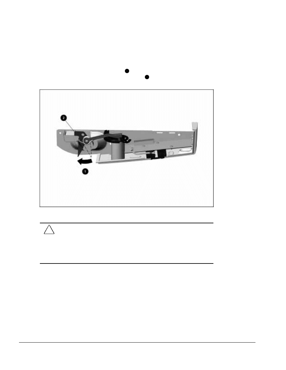
. . . . . . . . . . . . . . . . . . . . . . . . . . . . . . . . . . . . .
5-44
ArmadaStation Removal and Replacement Procedures
To install the control panel assembly, follow these steps:
1. Connect the control panel cable to the connector on the control panel assembly.
2. Rotate the security actuator clockwise
1
and push it toward the control panel
assembly until it locks on the indicated position
2
(Figure 5-42).
Figure 5-42. Rotating the Security Actuator to the Proper Position
CAUTION: Be careful when connecting the control panel cable to the control panel
assembly. The connectors only connect one way. Attempts to connect the cable the
wrong way can result in damage to the connectors on the control panel cable and control
panel assembly.
The connectors are properly seated and connected when the plastic connector housing
on the control panel cable fits flush in the plastic connector housing on the control panel
assembly.
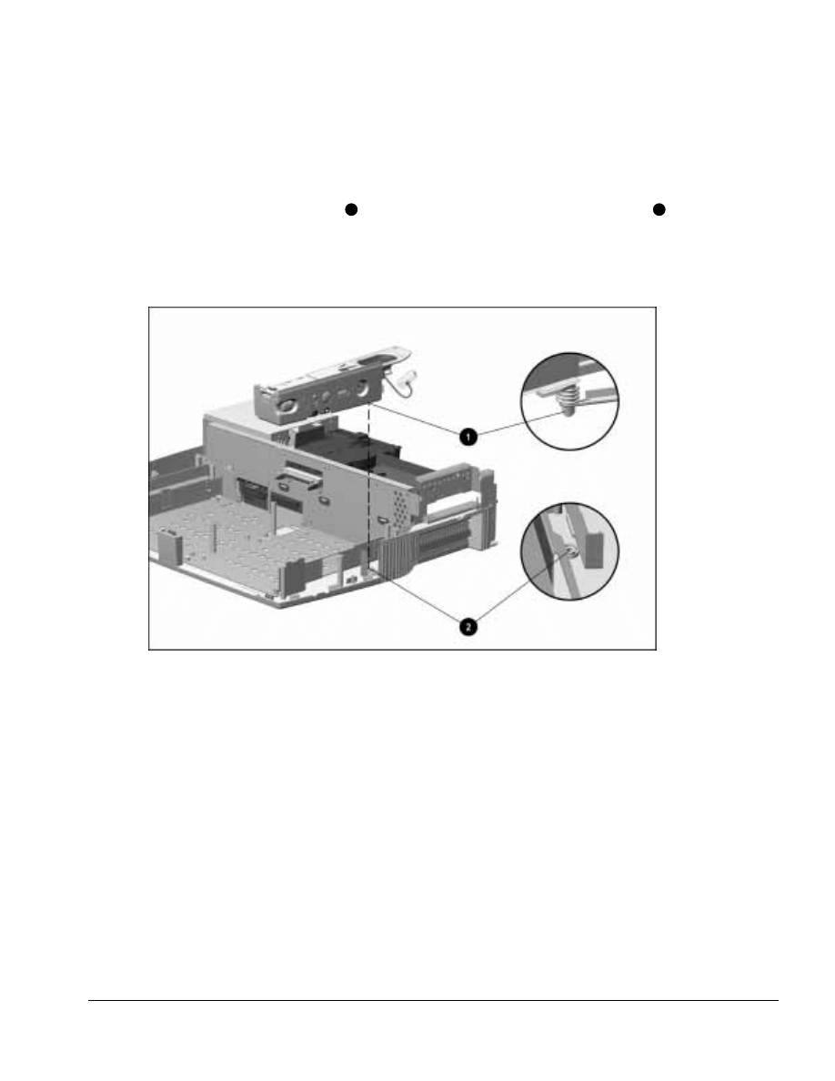
. . . . . . . . . . . . . . . . . . . . . . . . . . . . . . . . . . . . .
ArmadaStation Removal and Replacement Procedures
5-45
3. Bend the control panel ground cable up and over the top surface of the control panel
housing.
4. Insert the control panel assembly into the base assembly, making sure the pin on
which the actuator spring sits
1
fits into the alignment hole in the base assembly
2
(Figure 5-43).
NOTE: Be careful not to trip the security actuator during the control panel assembly
installation.
Figure 5-43. Installing the Control Panel Assembly
NOTE: Make sure the control panel cable does not get pinned underneath the control
panel assembly. The cable should rest in the right half-height bay when the control
panel assembly is installed.
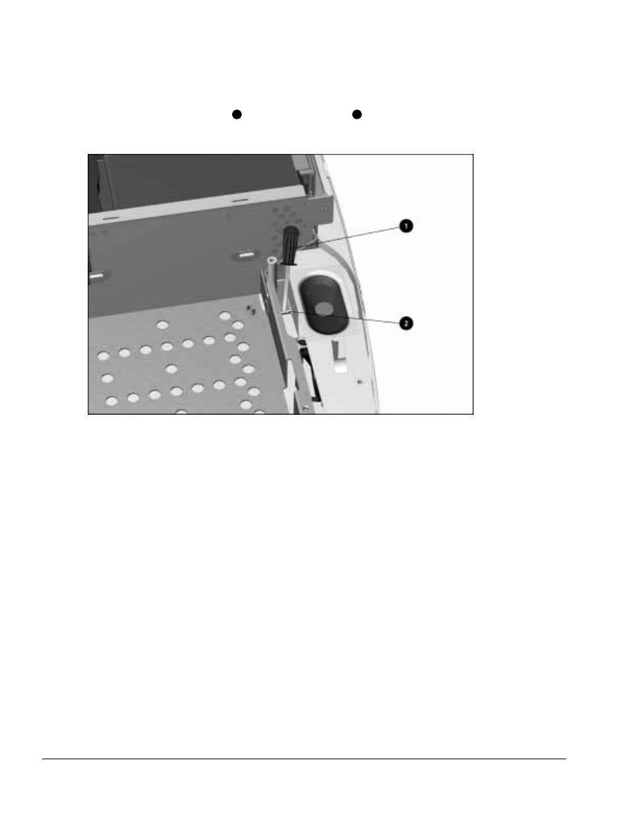
. . . . . . . . . . . . . . . . . . . . . . . . . . . . . . . . . . . . .
5-46
ArmadaStation Removal and Replacement Procedures
5. Use a flat-blade screwdriver
1
to trip the C/U actuator
2
into the proper position by
pushing down on the actuator tab (Figure 5-44).
Figure 5-44. Tripping the C/U Actuator
6. Install the screws securing the control panel assembly to the base assembly.
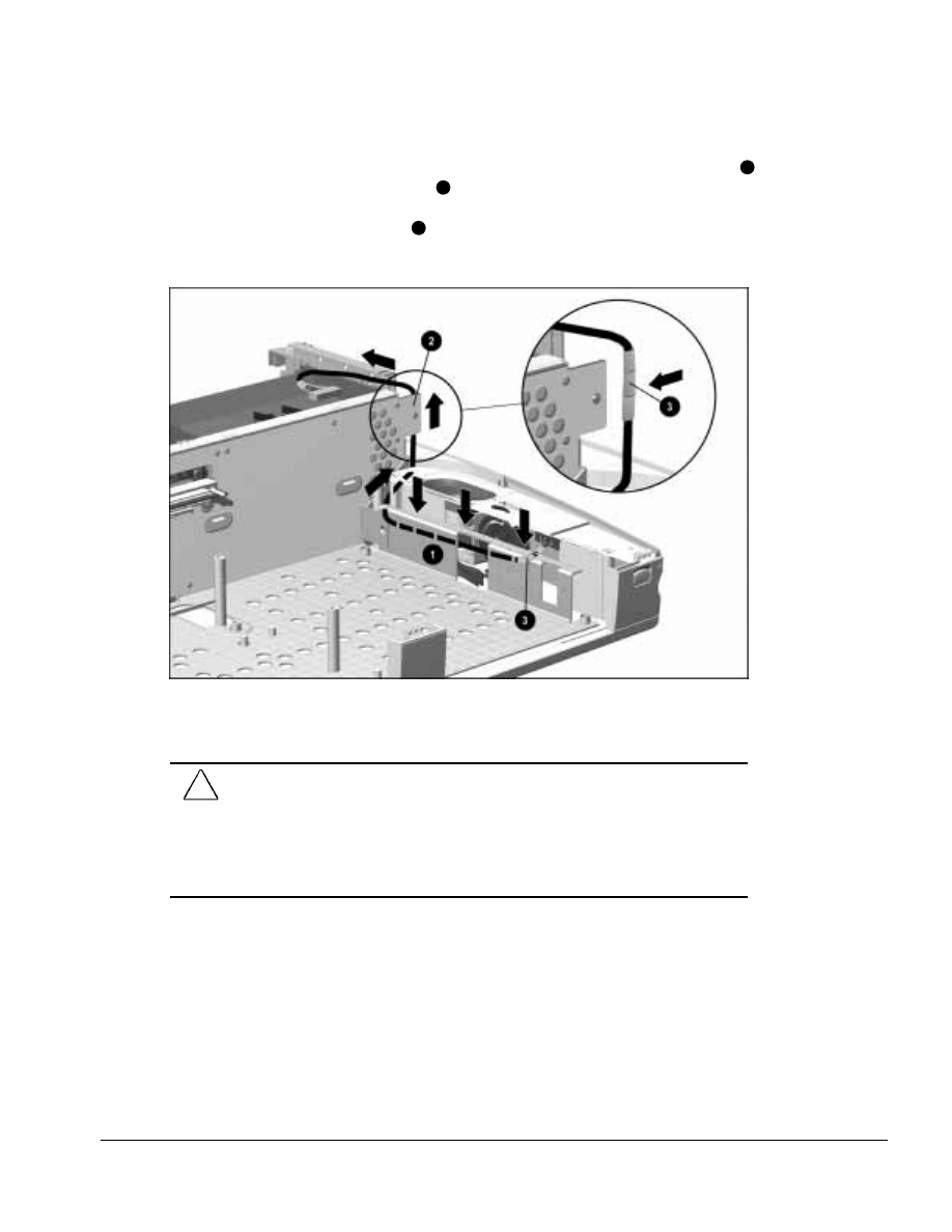
. . . . . . . . . . . . . . . . . . . . . . . . . . . . . . . . . . . . .
ArmadaStation Removal and Replacement Procedures
5-47
7. Route the control panel cable between the control panel and the base assemblies
1
and around the backplane assembly
2
(Figure 5-45). Make sure the protective
wrapping on the control panel cable protects the cable from the base assembly and
backplane assembly sheet metal
3
. The cable end with three pieces of protective
wrapping should be connected to the backplane assembly.
Figure 5-45. Proper Position of the Control Panel Cable
8. Connect the control panel cable to the connector on the backplane assembly.
CAUTION: Be careful when connecting the control panel cable to the backplane
assembly. The connectors only connect one way. Attempts to connect the cable the
wrong way can result in damage to the connectors on the control panel cable and
backplane assembly.
The connectors are properly seated and connected when the plastic connector housing
on the control panel cable fits flush in the plastic connector housing on the backplane
assembly.
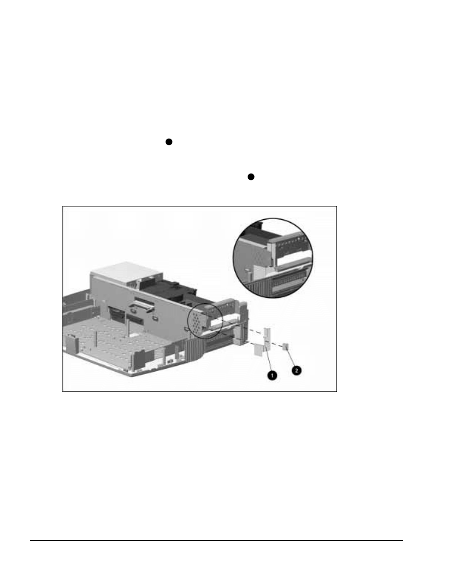
. . . . . . . . . . . . . . . . . . . . . . . . . . . . . . . . . . . . .
5-48
ArmadaStation Removal and Replacement Procedures
NOTE: When routing the control panel cable around the backplane assembly, inspect the
subpan side shield and backplane-brace spacer to determine if they should be replaced.
To replace these components, follow these steps:
1. Completely remove the old subpan side shield and backplane-brace spacer from the
backplane and base assemblies.
2. Insert the subpan side shield
1
between the backplane assembly and lower case
sheetmetal, making sure the square section of the shield is positioned in front of the
backplane assembly as illustrated in Figure 5-46.
3. Remove the backing from the backplane-brace spacer
2
and insert it between the
backplane assembly and the subpan side shield.
Figure 5-46. Replacing the Subpan Side Shield and Backplane-Brace Spacer
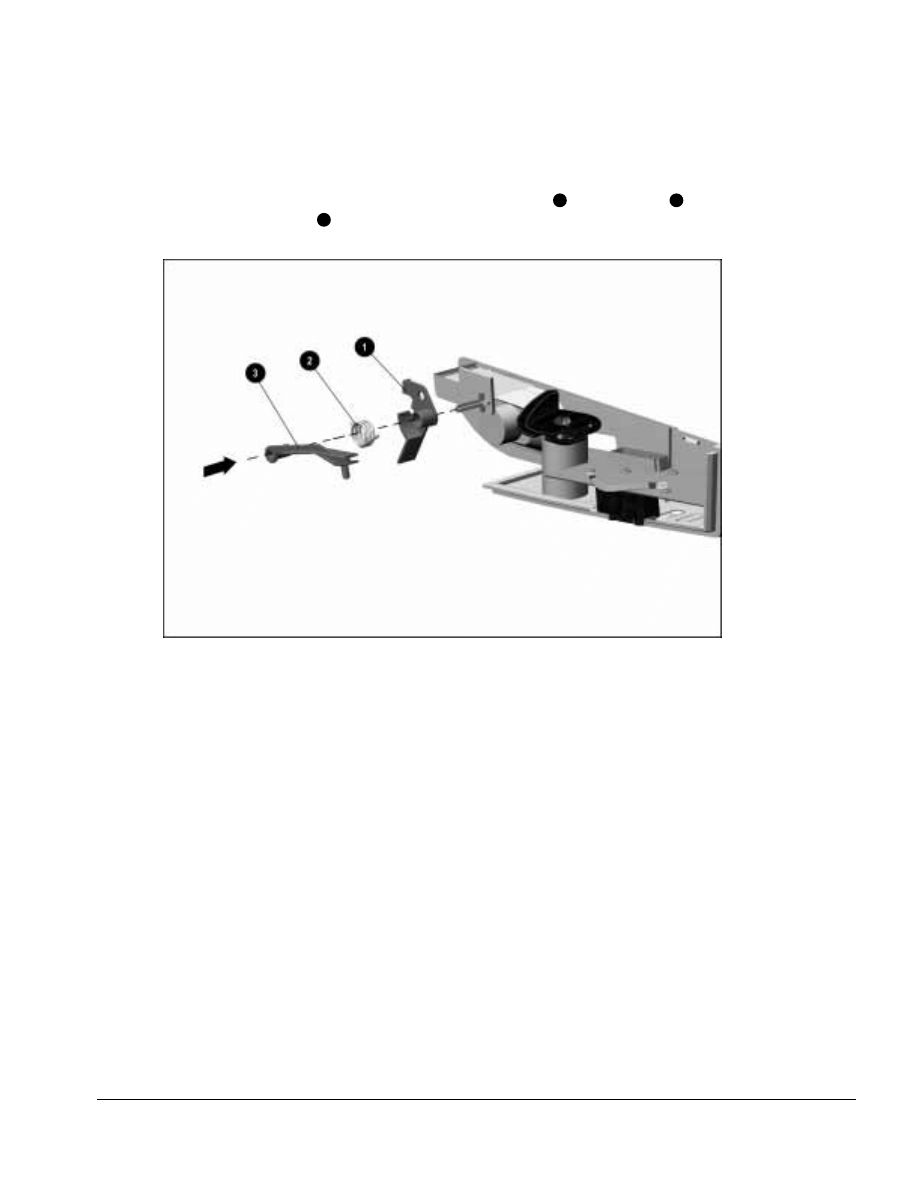
. . . . . . . . . . . . . . . . . . . . . . . . . . . . . . . . . . . . .
ArmadaStation Removal and Replacement Procedures
5-49
NOTE: The C/U actuator assembly should not be disassembled during removal and
installation of the control panel assembly. However, if it should be removed, refer to
Figure 5-47 for the proper position of the security actuator
1
, torsion spring
2
, and
MultiBay security arm
3
.
Figure 5-47. Proper Position of the C/U Actuator Assembly
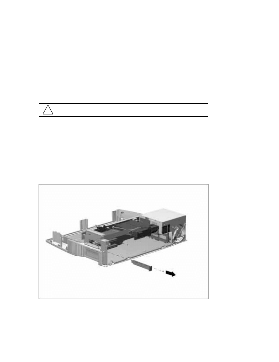
. . . . . . . . . . . . . . . . . . . . . . . . . . . . . . . . . . . . .
5-50
ArmadaStation Removal and Replacement Procedures
5.14 Expansion Boards
The ArmadaStation provides two slots for 32- or 64-bit PCI expansion boards and two
slots for 16-bit, full-length ISA expansion boards. Any combination of two of these
boards can be installed in the ArmadaStation.
For additional information, consult the documentation included with the
expansion boards.
!
WARNING: To reduce the risk of personal injury from hot surfaces, allow the internal
system components to cool before touching.
To install PCI and ISA boards in the ArmadaStation, follow these steps:
1. Prepare the ArmadaStation for disassembly (Section 5.3).
2. Remove the rear panel assembly (Section 5.5).
3. Remove the screw securing the expansion slot cover to the base assembly
(Figure 5-48). This screw is used later to secure the newly installed expansion board.
4. Remove the expansion slot cover.
Figure 5-48. Removing an Expansion Slot Cover
NOTE: Retain the expansion slot cover. It will be needed if the expansion board is
removed from the ArmadaStation.
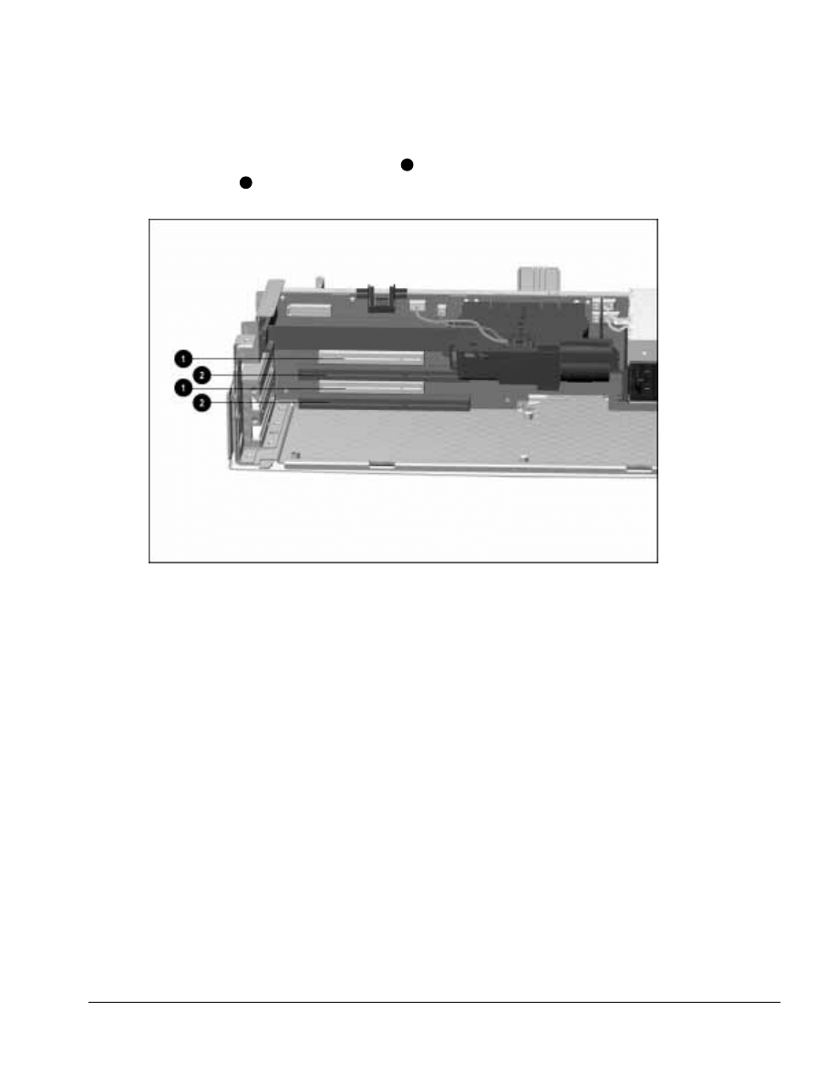
. . . . . . . . . . . . . . . . . . . . . . . . . . . . . . . . . . . . .
ArmadaStation Removal and Replacement Procedures
5-51
5. Select the slot into which the expansion board is to be inserted: PCI expansion
boards are installed in the shorter slots
1
; ISA expansion boards are installed in the
longer slots
2
(Figure 5-49).
Figure 5-49. Expansion Board Slots
6. Align the bracket on the left side of the expansion board with the expansion slot on
the left side of the ArmadaStation.
7. Push the expansion board into the expansion slot until the connector is seated.
8. Secure the expansion board to the base assembly by installing the screw removed in
Step 3.
Reverse the installation procedure described above to remove an expansion board.
Once an expansion board has been installed, its internal connector can be accessed on
the lower right side of the ArmadaStation. If the expansion board has a cable, refer to
the documentation included with the board for connection information.
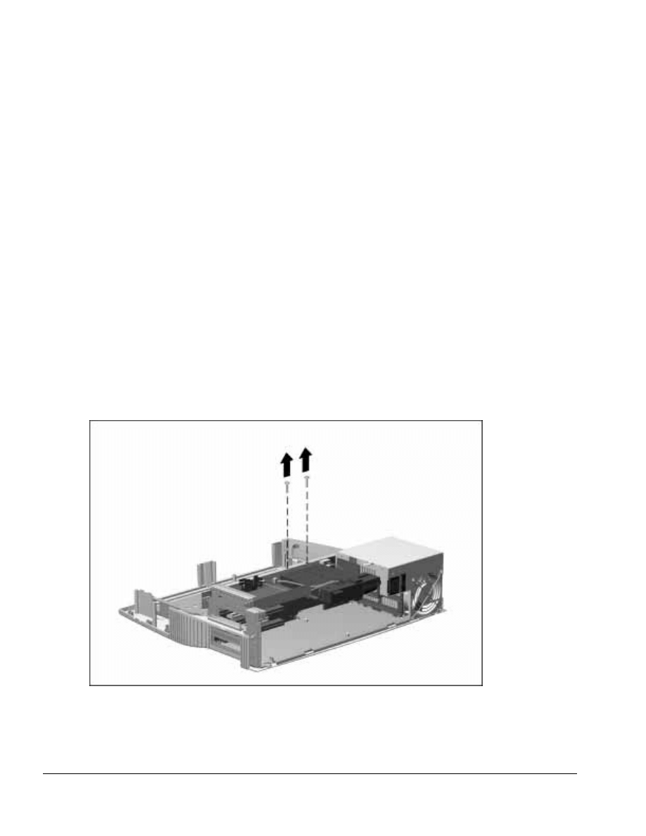
. . . . . . . . . . . . . . . . . . . . . . . . . . . . . . . . . . . . .
5-52
ArmadaStation Removal and Replacement Procedures
5.15 Mechanism Assembly
The mechanism assembly provides the motorized docking feature of the
ArmadaStation.
IMPORTANT: The mechanism assembly contains white lithium grease, which is used as
a lubricant. The assembly is spared as a unit and should not be disassembled.
To remove the mechanism assembly, follow these steps:
1. Prepare the ArmadaStation for disassembly (Section 5.3).
2. Remove the alignment tray assembly (Section 5.4).
3. Remove the rear panel assembly (Section 5.5).
4. Remove the upper case assembly (Section 5.6).
5. Remove the I/O assembly (Section 5.9).
6. Remove the top brace (Section 5.10).
7. Remove the two screws securing the mechanism assembly to the backplane assembly
(Figure 5-50).
Figure 5-50. Removing the Mechanism Assembly Screws
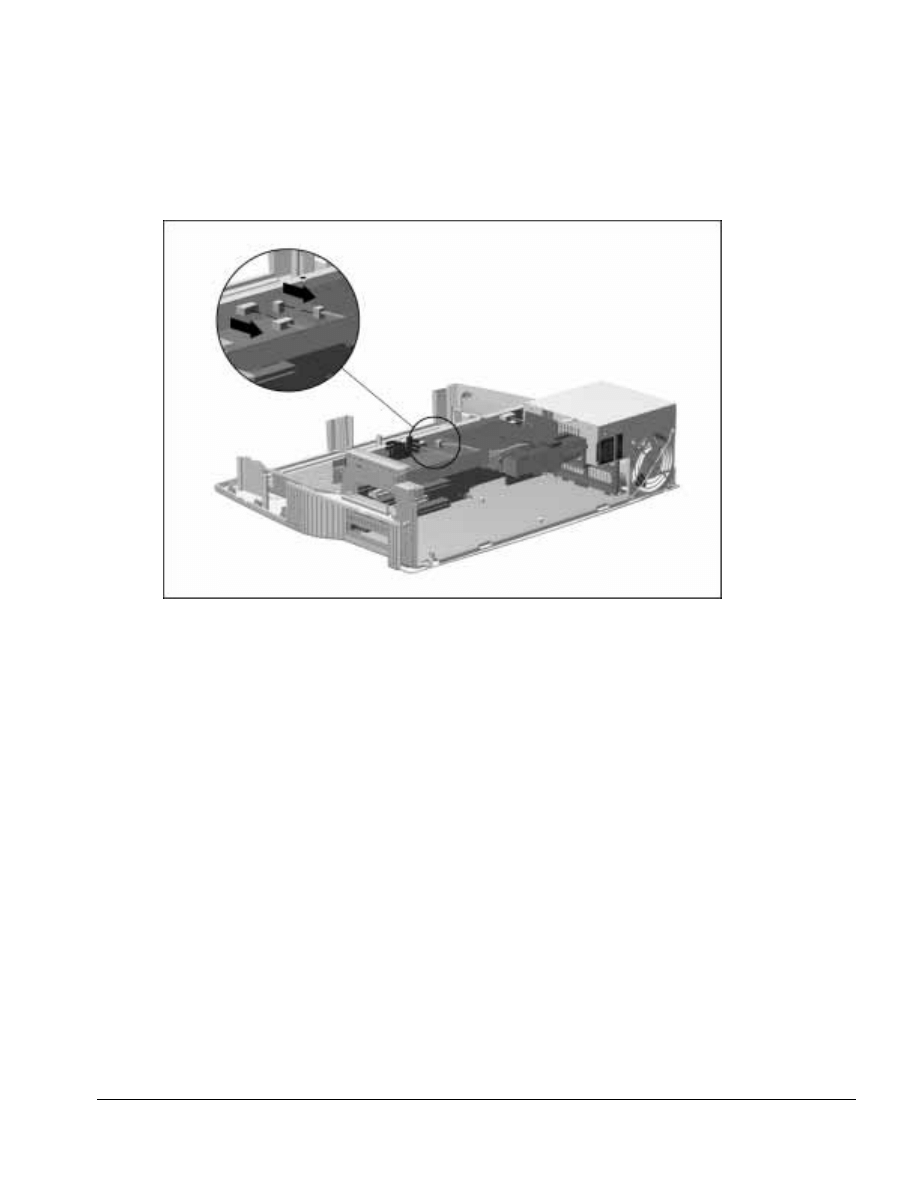
. . . . . . . . . . . . . . . . . . . . . . . . . . . . . . . . . . . . .
ArmadaStation Removal and Replacement Procedures
5-53
8. Disconnect the two mechanism assembly cables from the backplane assembly
(Figure 5-51).
Figure 5-51. Disconnecting the Mechanism Assembly Cables
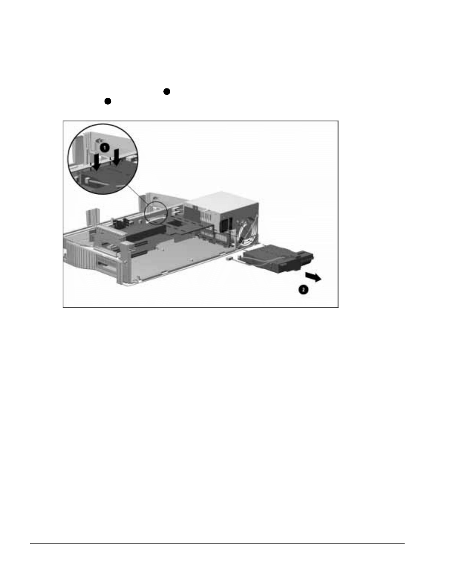
. . . . . . . . . . . . . . . . . . . . . . . . . . . . . . . . . . . . .
5-54
ArmadaStation Removal and Replacement Procedures
9. Remove the mechanism assembly by pressing down on the two square tabs on the
mechanism assembly cover
1
and pulling the assembly out of the backplane
assembly
2
(Figure 5-52).
Figure 5-52. Removing the Mechanism Assembly
Reverse the removal procedure described above to install the mechanism assembly.

. . . . . . . . . . . . . . . . . . . . . . . . . . . . . . . . . . . . .
ArmadaStation Removal and Replacement Procedures
5-55
5.16 Power Supply
The power supply is located in the left rear corner of the ArmadaStation. It is replaced
as an assembly with its fan. To remove the power supply, follow these steps:
CAUTION: Do not handle or carry the power supply by the wiring harness. This can
cause damage to the power supply and wiring harness.
1. Prepare the ArmadaStation for disassembly (Section 5.3).
2. Remove the alignment tray assembly (Section 5.4).
3. Remove the rear panel assembly (Section 5.5).
4. Remove the upper case assembly (Section 5.6).
5. Remove the I/O assembly (Section 5.9).
6. Remove the top brace (Section 5.10).
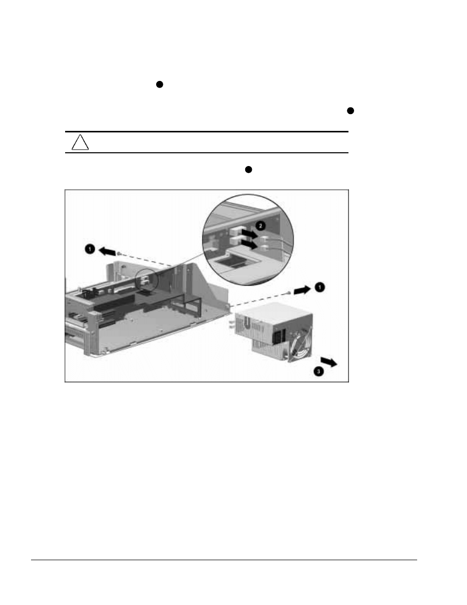
. . . . . . . . . . . . . . . . . . . . . . . . . . . . . . . . . . . . .
5-56
ArmadaStation Removal and Replacement Procedures
7. Remove the two screws
1
securing the power supply to the backplane assembly and
base assembly (Figure 5-53).
8. Disconnect the two cables attaching the power supply to the backplane assembly
2
.
CAUTION: Make sure the power supply cables are properly unclipped from the
backplane assembly before disconnecting the power supply cables.
9. Remove the power supply from the base assembly
3
.
Figure 5-53. Removing the Power Supply
Reverse the removal procedure described above to install the power supply assembly.

. . . . . . . . . . . . . . . . . . . . . . . . . . . . . . . . . . . . .
ArmadaStation Removal and Replacement Procedures
5-57
5.17 Backplane Assembly
The backplane assembly consists of the backplane board, backplane brace, docking
connector, alignment pins, and the backplane shield. The backplane assembly is spared
as a unit.
To remove the backplane assembly, follow these steps:
1. Prepare the ArmadaStation for disassembly (Section 5.3).
2. Remove the alignment tray assembly (Section 5.4).
3. Remove the rear panel assembly (Section 5.5).
4. Remove the upper case assembly (Section 5.6).
5. Remove the drive cage shield (Section 5.7).
6. Disconnect the hard drive, diskette drive, CD-ROM/audio, and MultiBay cables from
the backplane assembly (Section 5.8).
7. Disconnect the left speaker assembly cable from the backplane assembly
(Section 5.11).
8. Remove the I/O assembly (Section 5.9).
9. Remove the top brace (Section 5.10).
10. Disconnect and untuck the control panel cable from the backplane assembly (Section
5.13).
11. Remove any installed PCI or ISA expansion boards from the backplane assembly
(Section 5.14).
12. Remove the mechanism assembly (Section 5.15).
13. Remove the power supply (Section 5.16).
14. Position the ArmadaStation so the front is facing forward.
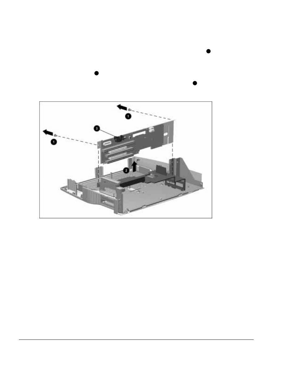
. . . . . . . . . . . . . . . . . . . . . . . . . . . . . . . . . . . . .
5-58
ArmadaStation Removal and Replacement Procedures
15. Remove the two screws securing the backplane assembly to the base assembly
1
(Figure 5-54).
16. Grasp the top of the backplane assembly and lift up on the assembly and remove it
from the base assembly
2
.
NOTE: When removing the backplane assembly, do not use the heatsink
3
to lift the
assembly.
Figure 5-54. Removing the Backplane Assembly
Reverse the removal procedure described above to install the backplane assembly.

. . . . . . . . . . . . . . . . . . . . . . . . . . . . . . . . . . . . .
ArmadaStation Removal and Replacement Procedures
5-59
5.18 Expansion Card Cage
The expansion card cage separates the expansion cards and I/O assembly from the
power supply and mechanism assembly. It also provides structural support for the
mechanism assembly and power supply.
To remove the expansion card cage, follow these steps:
1. Prepare the ArmadaStation for disassembly (Section 5.3).
2. Remove the alignment tray assembly (Section 5.4).
3. Remove the rear panel assembly (Section 5.5).
4. Remove the upper case assembly (Section 5.6).
5. Remove the I/O assembly (Section 5.9).
6. Remove the top brace (Section 5.10).
7. Disconnect and untuck the control panel cable from the backplane assembly (Section
5.13).
8. Remove the mechanism assembly (Section 5.15).
9. Remove the power supply (Section 5.16).
10. Remove the backplane assembly (Section 5.17).
11. Position the ArmadaStation so the left side is facing forward.
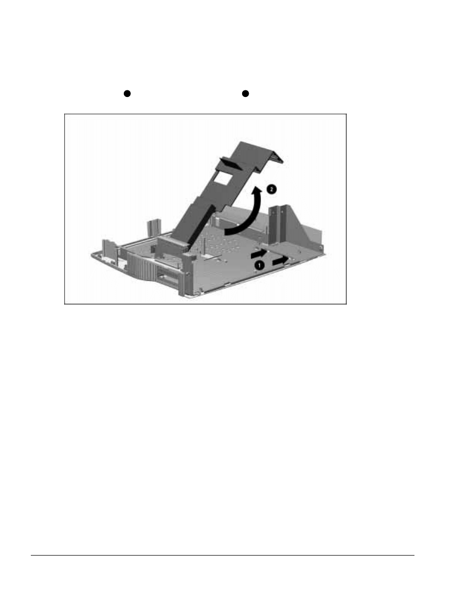
. . . . . . . . . . . . . . . . . . . . . . . . . . . . . . . . . . . . .
5-60
ArmadaStation Removal and Replacement Procedures
12. Flex the right bottom side of the expansion card cage away from the retainer on the
base assembly
1
and swing the cage up and away
2
(Figure 5-55).
Figure 5-55. Releasing the Expansion Card Cage
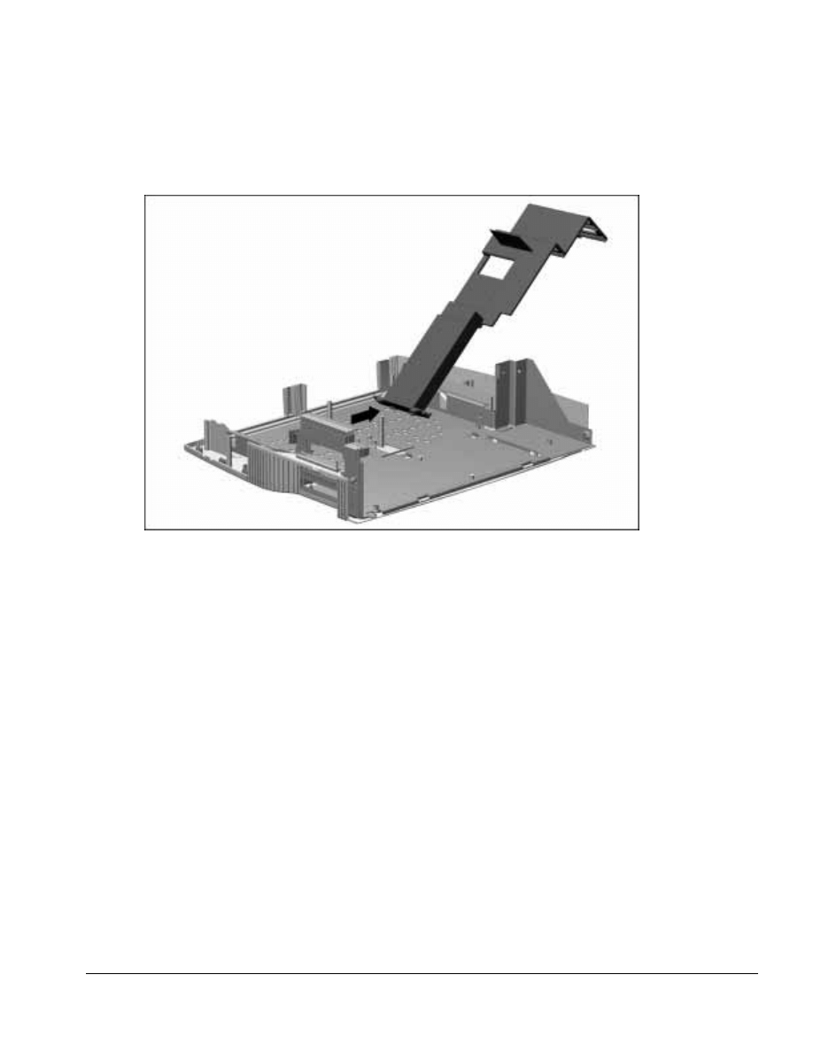
. . . . . . . . . . . . . . . . . . . . . . . . . . . . . . . . . . . . .
ArmadaStation Removal and Replacement Procedures
5-61
13. Swing the expansion card cage to the right until the tabs on the right side of the cage
clear the slots in the base assembly (Figure 5-56).
Figure 5-56. Removing the Expansion Card Cage
Reverse the removal procedure described above to install the backplane assembly.
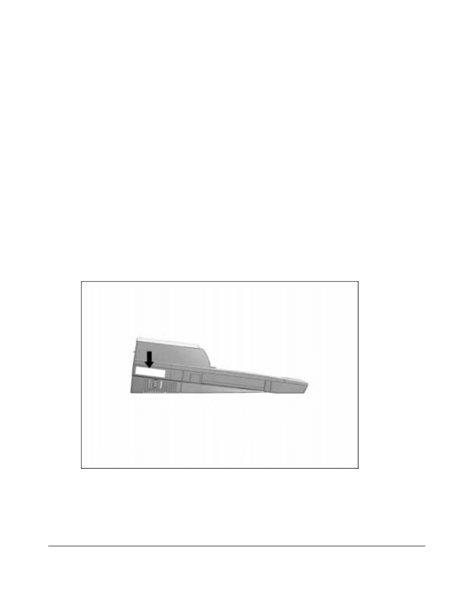
. . . . . . . . . . . . . . . . . . . . . . . . . . . . . . . . . . . . .
Chapter 6
Armada MiniStation Removal and Replacement Procedures
6-1
Armada MiniStation Removal and
Replacement Procedures
This chapter presents the removal and replacement procedures for the Armada
MiniStation.
NOTE: This chapter contains instructions that refer to the Armada MiniStation in its two
optional models: the Armada MiniStation E (Ethernet capability) and the Armada
MiniStation EX (Ethernet, MultiBay, battery charging bay, and PC Card capabilities).
When a set of instructions refers to the “Armada MiniStation,” the instructions pertain
to both models. Otherwise, “E” or “EX” is used to indicate the specific model base.
6.1 Serial Number
The Armada MiniStation serial number should be reported to Compaq when requesting
information or ordering spare parts. The serial number is displayed on the left side of
the Armada MiniStation (Figure 6-1).
Figure 6-1. Armada MiniStation Serial Number Location

. . . . . . . . . . . . . . . . . . . . . . . . . . . . . . . . . . . . .
6-2
Armada MiniStation Removal and Replacement Procedures
6.2 Disassembly Sequence Chart
Use the chart below to determine the section number and disassembly sequence for
removing components from the Armada MiniStation.
6.3 Preparing the Armada MiniStation for
Disassembly
6.4 External Components
Compaq Logo
Armada MiniStation Feet
6.5 Enclosure Cover
6.6 Module Assembly
6.7 Power Supply
6.8 MultiBay/PC Card Assembly
Figure 6-2. Armada MiniStation Disassembly Sequence Chart
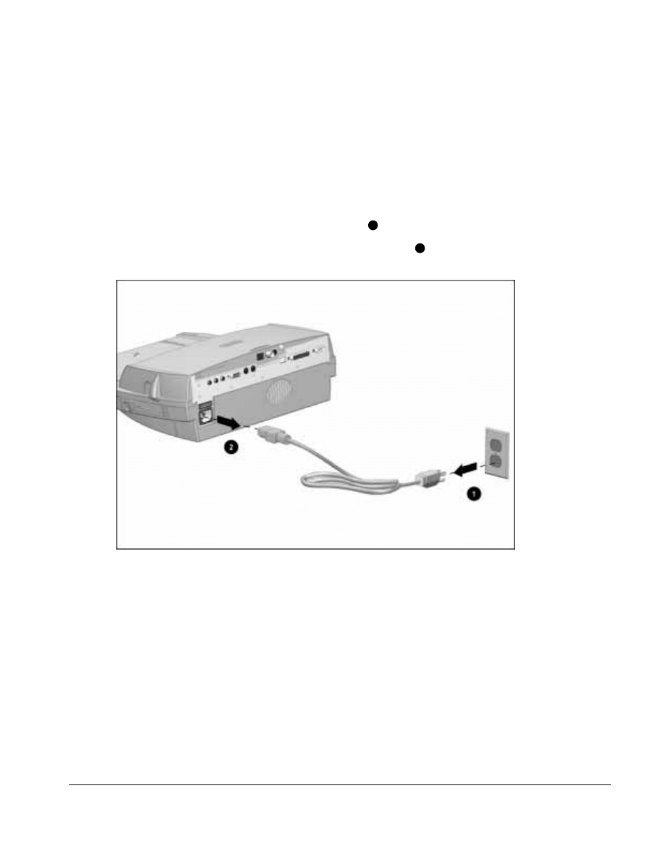
. . . . . . . . . . . . . . . . . . . . . . . . . . . . . . . . . . . . .
Armada MiniStation Removal and Replacement Procedures
6-3
6.3 Preparing the Armada MiniStation
for Disassembly
Before beginning removal and replacement procedures, follow these steps:
1. Turn the Armada MiniStation EX keylock counterclockwise to unlock it.
2. Undock the computer from the Armada MiniStation.
3. Disconnect the power cord from the wall outlet
1
(Figure 6-3).
4. Disconnect the power cord from the Armada MiniStation
2
.
Figure 6-3. Disconnecting the Armada MiniStation
5. Disconnect external devices.
6. If installed, remove the battery pack from the battery charging bay (Armada
MiniStation EX only).
7. If installed, remove the MultiBay device from the MultiBay (Armada
MiniStation EX only).
8. If installed, remove the PC Cards from the PC Card slots (Armada MiniStation EX
only).
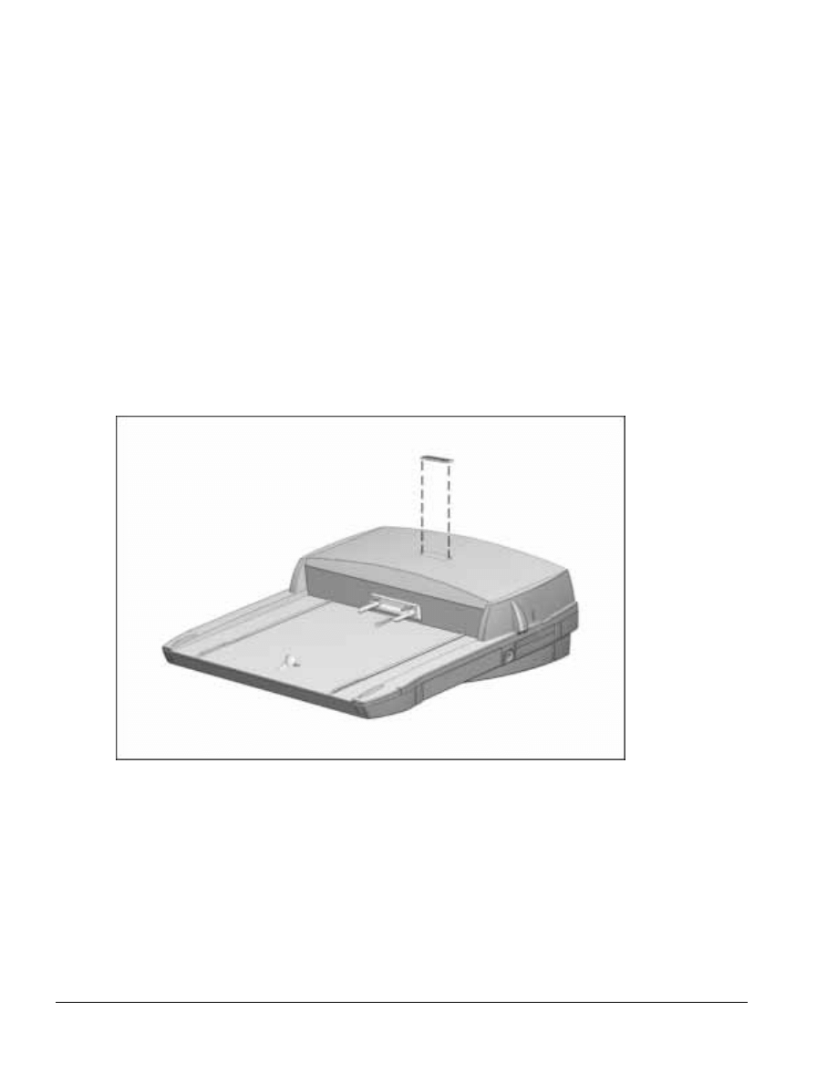
. . . . . . . . . . . . . . . . . . . . . . . . . . . . . . . . . . . . .
6-4
Armada MiniStation Removal and Replacement Procedures
6.4 External Components
This section describes the removal and replacement procedures that do not require
access to the internal components of the Armada MiniStation. This includes:
■ Compaq logo
■ Feet
Compaq Logo
A Compaq logo should be installed on the Armada MiniStation or monitor support
cover only if the old logo is damaged or removed. The logo is an adhesive-backed label.
Remove the protective covering from the adhesive back, and install the logo in its
location on the Armada MiniStation (Figure 6-4). The logo reads from left to right
when viewed from the front of the unit.
Figure 6-4. Installing a Compaq Logo
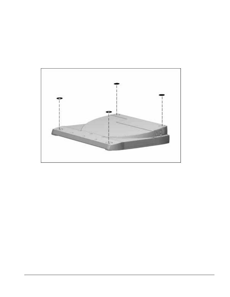
. . . . . . . . . . . . . . . . . . . . . . . . . . . . . . . . . . . . .
Armada MiniStation Removal and Replacement Procedures
6-5
Armada MiniStation Feet
The feet for the Armada MiniStation are round, adhesive-backed rubber pads. Install the
feet by removing the protective covering from the adhesive back and placing the feet in
their positions on the bottom of the Armada MiniStation (Figure 6-5).
Figure 6-5. Installing Armada MiniStation Feet
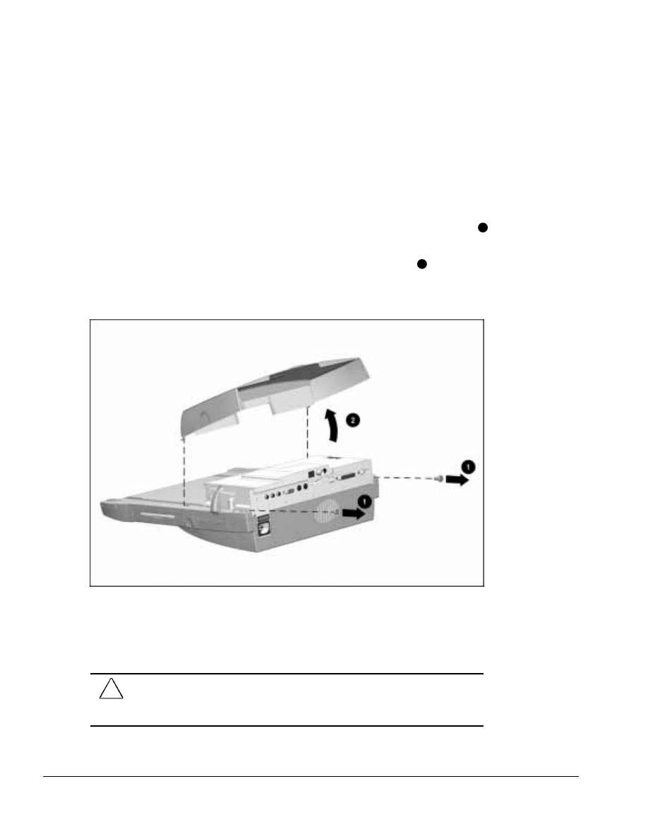
. . . . . . . . . . . . . . . . . . . . . . . . . . . . . . . . . . . . .
6-6
Armada MiniStation Removal and Replacement Procedures
6.5 Enclosure Cover
The enclosure cover is spared as a unit. To remove the enclosure cover, follow these
steps:
1. Prepare the Armada MiniStation for disassembly (Section 6.3).
2. Position the Armada MiniStation so the rear panel faces forward.
3. Remove the two screws securing the enclosure cover to the module assembly
1
(Figure 6-6).
4. Grasp the sides of the enclosure cover and swing it up and away
2
until the tabs
on the front of the enclosure cover clear the base assembly. Make sure the docking
lever does not interfere with the removal of the enclosure cover.
Figure 6-6. Removing the Enclosure Cover
Reverse the removal procedure described above to install the enclosure cover. When
installing the enclosure cover, make sure the alignment pins on the outside edge of the
cover fit into the alignment holes on the upper case.
CAUTION: When installing the enclosure cover, make sure the right side of the cover fits
inside the docking lever and the left side of the cover does not pinch the power supply
cable. Failure to follow this caution can result in damage to the docking lever and power
supply cable.
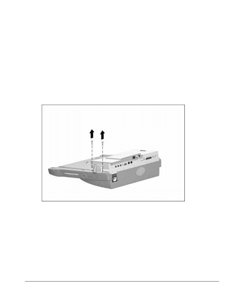
. . . . . . . . . . . . . . . . . . . . . . . . . . . . . . . . . . . . .
Armada MiniStation Removal and Replacement Procedures
6-7
6.6 Module Assembly
The module assembly is located underneath the enclosure cover. To remove the module
assembly, follow these steps:
1. Prepare the Armada MiniStation for disassembly (Section 6.3).
2. Remove the enclosure cover (Section 6.5).
3. Position the Armada MiniStation so the right side is facing forward.
4. Remove the two screws securing the module assembly to the base assembly
(Figure 6-7).
Figure 6-7. Removing the Module Assembly Screws
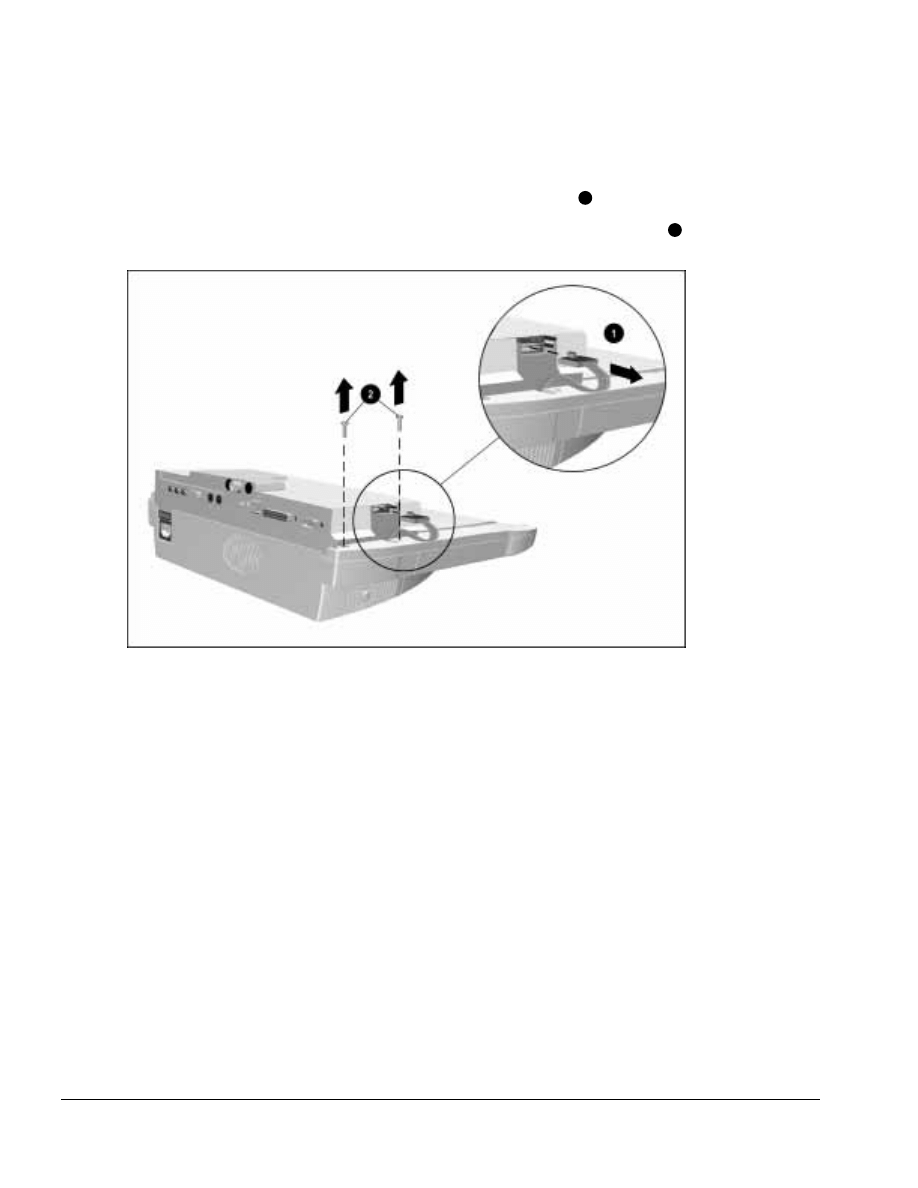
. . . . . . . . . . . . . . . . . . . . . . . . . . . . . . . . . . . . .
6-8
Armada MiniStation Removal and Replacement Procedures
5. Position the Armada MiniStation so the left side is facing forward.
6. Disconnect the power supply cable from the module assembly
2
(Figure 6-8).
7. Remove the two screws securing the module assembly to the base assembly
2
.
Figure 6-8. Removing the Module Assembly Screws and Disconnecting the Power Supply Cable
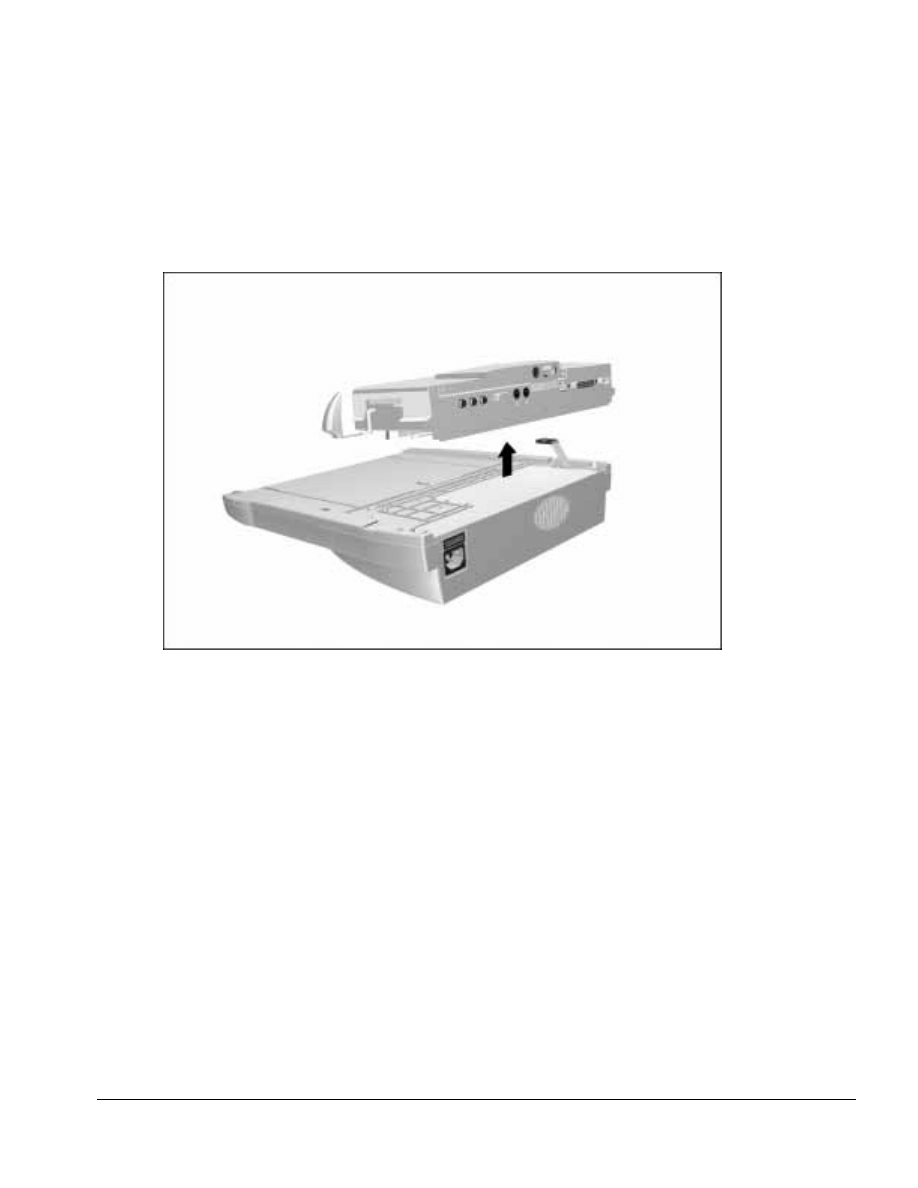
. . . . . . . . . . . . . . . . . . . . . . . . . . . . . . . . . . . . .
Armada MiniStation Removal and Replacement Procedures
6-9
8. Lift the module assembly away from the base assembly (Figure 6-9).
NOTE: The Armada MiniStation EX module assembly includes a multiple-pin
connector that is firmly connected to the MultiBay/PC Card assembly. Pull firmly
to disconnect the module assembly from the MultiBay/PC Card assembly.
Figure 6-9. Removing the Module Assembly
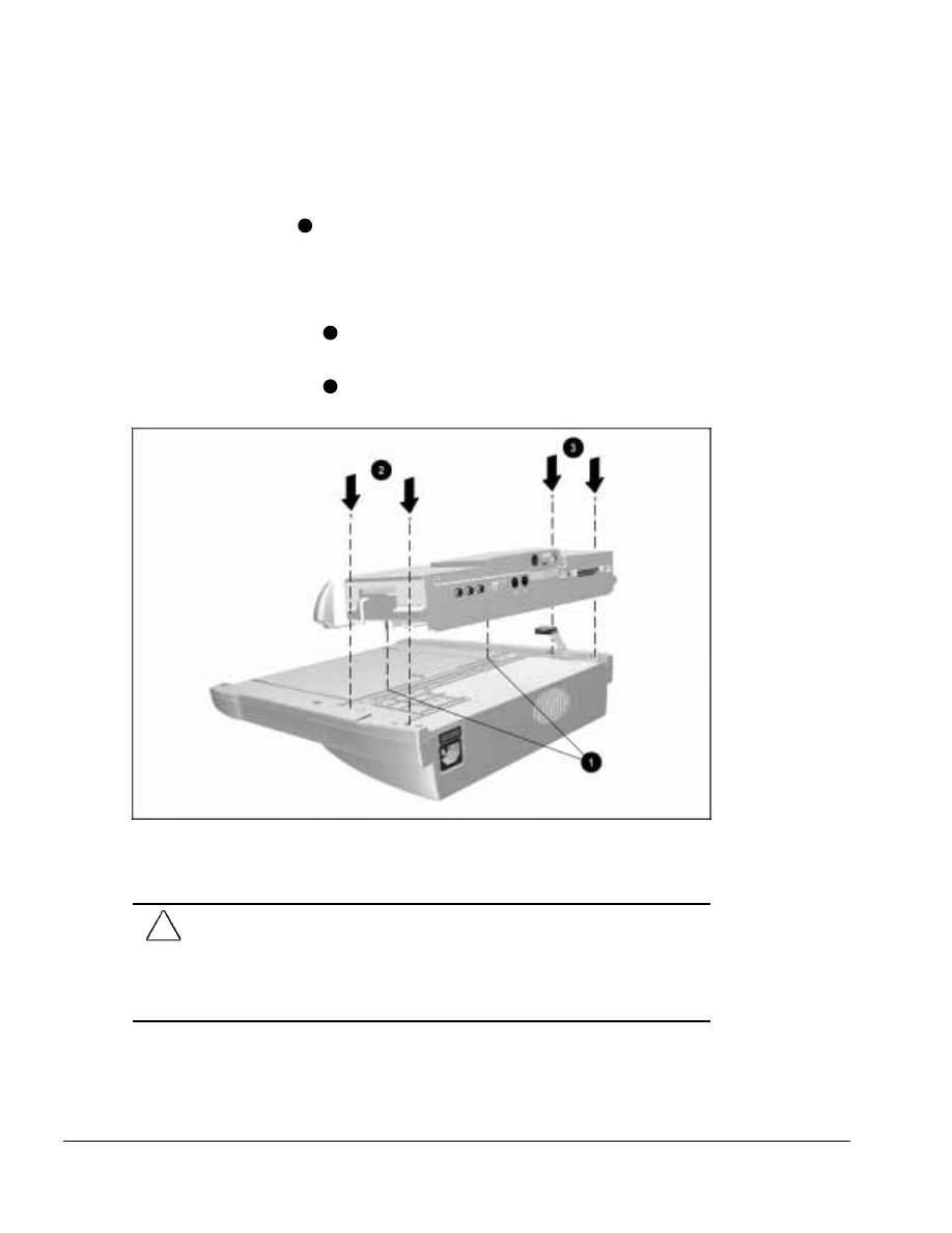
. . . . . . . . . . . . . . . . . . . . . . . . . . . . . . . . . . . . .
6-10
Armada MiniStation Removal and Replacement Procedures
To install the module assembly, follow these steps:
1. Align the alignment pins on the bottom of the module assembly with the holes in
the base assembly
1
and place the module assembly on the base assembly (Figure
6-10).
2. Press firmly on the front of the module assembly to properly seat the module
assembly connector board.
3. Install the two screws
2
on the right side (the side with the docking lever) of the
assembly.
4. Install the two screws
3
on the left side of the assembly.
Figure 6-10. Installing the Module Assembly
5. Connect the power supply cable.
CAUTION: Be careful when installing and removing the module assembly on the Armada
MiniStation EX model. The assembly includes a multiple-pin connector that must be
connected to the MultiBay/PC Card assembly. Even, firm pressure must be applied to
connect the module assembly to the MultiBay/PC Card assembly.
Failure to exercise caution when installing the module assembly can result in damage to
the connectors on the docking module and MultiBay/PC Card assemblies.
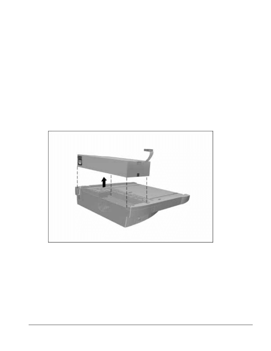
. . . . . . . . . . . . . . . . . . . . . . . . . . . . . . . . . . . . .
Armada MiniStation Removal and Replacement Procedures
6-11
6.7 Power Supply
The screws securing the module assembly to the base assembly also secure the power
supply. Once these screws have been removed (Section 6.7), the power supply can also
be removed.
To remove the power supply, follow these steps:
1. Prepare the Armada MiniStation for disassembly (Section 6.3).
2. Remove the enclosure cover (Section 6.5).
3. Remove the module assembly (Section 6.6).
4. Lift the power supply out of the base assembly (Figure 6-11).
Figure 6-11. Removing the Power Supply
Reverse the removal procedure described above to install the power supply.

. . . . . . . . . . . . . . . . . . . . . . . . . . . . . . . . . . . . .
6-12
Armada MiniStation Removal and Replacement Procedures
6.8 MultiBay/PC Card Assembly
(Armada MiniStation EX only)
The MultiBay/PC Card Assembly provides the Armada MiniStation EX with a
MultiBay, a battery charging bay, and two PC Card slots. MultiBay devices supported
by the computer and ArmadaStation can be used in the Armada MiniStation EX.
CAUTION: Be careful when removing and installing the MultiBay/PC Card assembly. The
assembly includes a multiple-pin connector that must be connected to the module
assembly. Firm, even pressure must be applied to connect the MultiBay/PC Card
assembly to the module assembly.
Failure to exercise caution when removing and installing the MultiBay/PC Card assembly
can result in damage to the connectors on the docking module and MultiBay/PC Card
assemblies.
To remove the MultiBay/PC Card assembly, follow these steps:
1. Prepare the Armada MiniStation EX for disassembly (Section 6.3).
2. Turn the Armada MiniStation EX upside down.
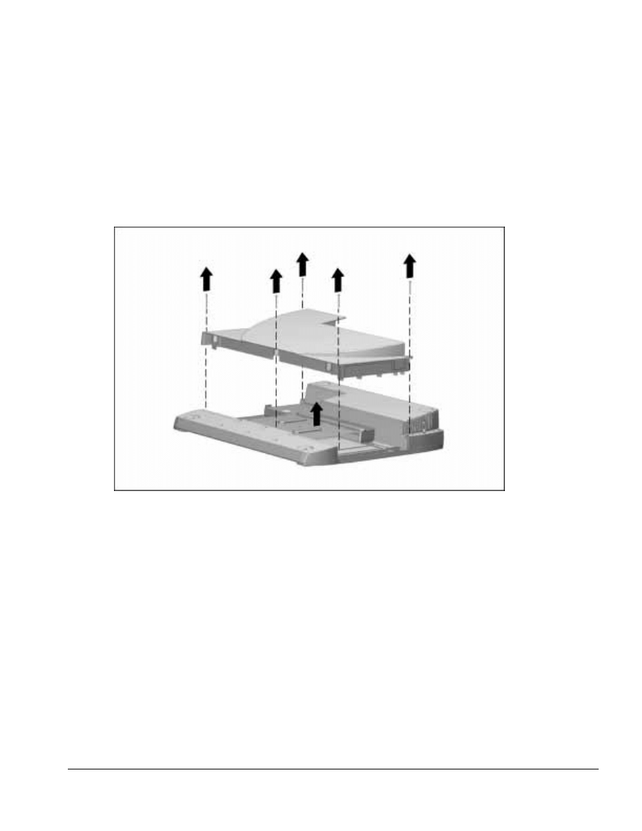
. . . . . . . . . . . . . . . . . . . . . . . . . . . . . . . . . . . . .
Armada MiniStation Removal and Replacement Procedures
6-13
3. Remove the five screws securing the MultiBay/PC Card assembly to the base
assembly (Figure 6-12).
4. Remove the MultiBay/PC Card assembly.
NOTE: The MultiBay/PC Card assembly includes a multiple-pin connector that is
firmly connected to the module assembly. Pull firmly to disconnect the
MultiBay/PC Card assembly from the module assembly.
Figure 6-12. Removing the MultiBay/PC Card Assembly
Reverse the removal procedure to install the MultiBay/PC Card assembly.

. . . . . . . . . . . . . . . . . . . . . . . . . . . . . . . . . . . . .
Chapter 7
Specifications
7-1
Specifications
This chapter provides physical and performance specifications for the ArmadaStation
and Armada MiniStation.
7.1 ArmadaStation Physical and
Environmental Specifications
Table 7-1
ArmadaStation Physical and Environmental Specifications
U.S.
Metric
Dimensions
Height
With Monitor Support Cover
5.6 in
14.2 cm
Without Monitor Support Cover
5.0 in
12.7 cm
Depth
16.0 in
40.6 cm
Width
17.3 in
46.5 cm
Weight
ArmadaStation
22.7 lb
10.3 kg
Monitor Support Cover
3.3 lb
1.5 kg
Power Supply (Input)
Operating Voltage
90 to 260 VAC
Operating Current
5.0 Amp Maximum
Rated Voltage
100-120 to 220-240 VAC
Rated Current
2.5 to 5.0 Amps
Rated Line Frequency
50 - 60 Hz
Temperature
Operating
50 to 95
°
F
10 to 35
°
C
Nonoperating
-22 to 140
°
F
-30 to 60
°
C
Relative Humidity
Operating
20 to 80%
Nonoperating
5 to 90%
Altitude
Operating
10,000 ft
3048 m
Nonoperating
30,000 ft
9144 m
Shock
Operating
5 G, 11 ms, half sine
Nonoperating
140 G, 2 ms, half sine
Vibration
Operating
0.25 G, 10 to 500 Hz sine
0.25 octave/min sweep
Nonoperating
0.75 G, 10 to 500 Hz sine
0.50 octave/min sweep
Heat Dissipation
Btu/hr
kg-cal/min
Monitor support cover(maximum)
55 lb
25 kg

. . . . . . . . . . . . . . . . . . . . . . . . . . . . . . . . . . . . .
7-2
Specifications
7.2 Armada MiniStation Physical
and Environmental Specifications
Table 7-2
Armada MiniStation Physical and Environmental Specifications
U.S.
Metric
Dimensions
Height
With Monitor Support Cover
5.60 in
14.20 cm
Without Monitor Support Cover
5.00 in
12.70 cm
Depth
15.37 in
39.05 cm
Width
14.75 in
37.47 cm
Weight
Armada MiniStation E
7.67 lb
3.48 kg
Armada MiniStation EX
11.50 lb
5.23 kg
Monitor Support Cover
3.30 lb
1.50 kg
Power Supply (Input)
Operating Voltage
90 to 260 VAC
Operating Current
3.0 Amp Maximum
Rated Voltage
100-120 to 220-240 VAC
Rated Current
1.5 to 3.0 Amps
Rated Line Frequency
50 to 60 Hz
Temperature
Operating
50 to 95
°
F
10 to 35
°
C
Nonoperating
-22 to 140
°
F
-30 to 60
°
C
Relative Humidity
Operating
20 to 80%
Nonoperating
5 to 90%
Altitude
Operating
10,000 ft
3048 m
Nonoperating
30,000 ft
9144 m
Shock
Operating
5 G, 11 ms, half sine
Nonoperating
140 G, 2 ms, half sine
Vibration
Operating
0.25 G, 10 to 500 Hz sine
0.25 octave/min sweep
Nonoperating
0.75 G, 10 to 500 Hz sine
0.5 octave/min sweep
Heat Dissipation
Btu/hr
kg-cal/min
Monitor support cover(maximum)
55 lb
25 kg
The ArmadaStation and Armada MiniStation are designed in accordance with ANSI
specifications (no. X3.131-1993, Rev 10h) and IEEE 802.3 specifications.
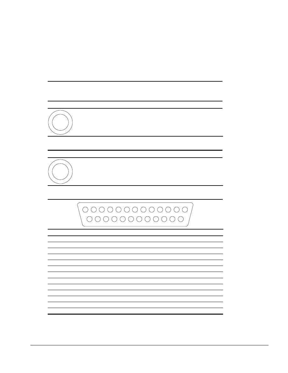
. . . . . . . . . . . . . . . . . . . . . . . . . . . . . . . . . . . . .
Appendix A
Connector Pin Assignments
A-1
Connector Pin Assignments
This appendix contains the pin assignments for all external connectors.
Table A-1
Headphone Jack
(ArmadaStation only)
Connector
Pin
Signal
1
2
1
2
Audio out
Ground
Table A-2
Microphone Jack
Connector
Pin
Signal
1
2
1
2
Audio in
Ground
Table A-3
Parallel Connector
1
2
3
4
15
16
17
14
5
6
7
8
9
10
11
12
13
18
20
19
21
22
23
25
24
Pin
Signal
Pin
Signal
1
Strobe
14
Auto Linefeed
2
Data Bit 0
15
Error
3
Data Bit 1
16
Initialize
4
Data Bit 2
17
Select In
5
Data Bit 3
18
Ground
6
Data Bit 4
19
Ground
7
Data Bit 5
20
Ground
8
Data Bit 6
21
Ground
9
Data Bit 7
22
Ground
10
Acknowledge
23
Ground
11
Busy
24
Ground
12
Paper End
25
Ground
13
Select
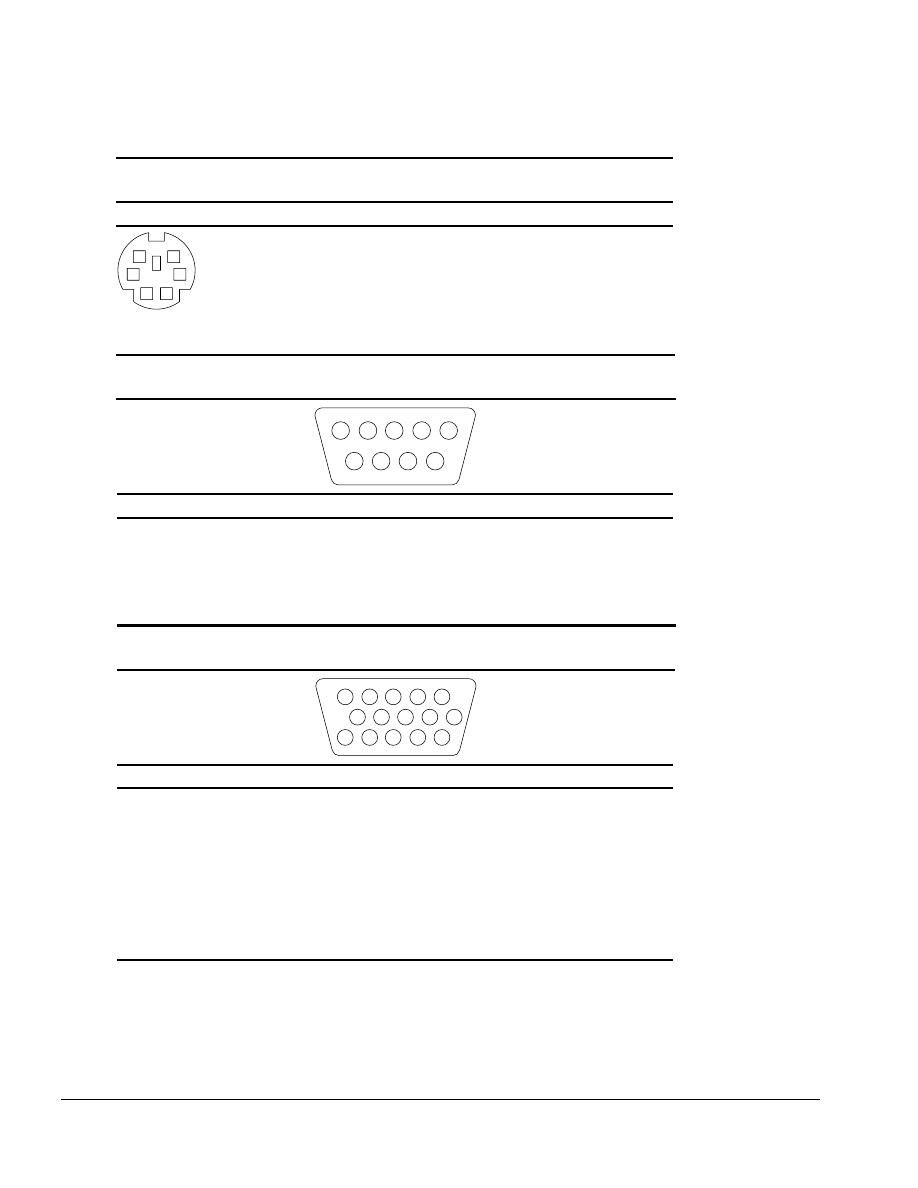
. . . . . . . . . . . . . . . . . . . . . . . . . . . . . . . . . . . . .
A-2
Connector Pin Assignments
Table A-4
External Keyboard/Mouse Connector
Connector
Pin
Signal
KEY
6
5
4
3
2
1
1
2
3
4
5
6
Keyboard/Mouse DATA
Keyboard/Mouse DATA
Ground
+5 VDC
Keyboard/Mouse CLK
Keyboard/Mouse CLK
Table A-5
Serial Connector
4
9
8
5
2
7
6
1
3
Pin
Signal
Pin
Signal
1
Carrier Detect
6
Data Set Ready
2
Receive Data
7
Ready to Send
3
Transmit Data
8
Clear to Send
4
Data Terminal Ready
9
Ring Indicator
5
Ground
Table A-6
External Monitor Connector
1
6
2
3
8
7
4
5
10
KEY
11
12
13
14
15
Pin
Signal
Pin
Signal
1
Red Analog
9
+5 Volt Supply
2
Green Analog
10
Ground
3
Blue Analog
11
Monitor ID Bit 0
4
Monitor ID Bit 2
12
Monitor ID Bit 1 (SDA)
5
Ground
13
Horizontal Sync
6
Ground
14
Vertical Sync
7
Ground
15
Monitor ID Bit 3 (SCL)
8
Ground
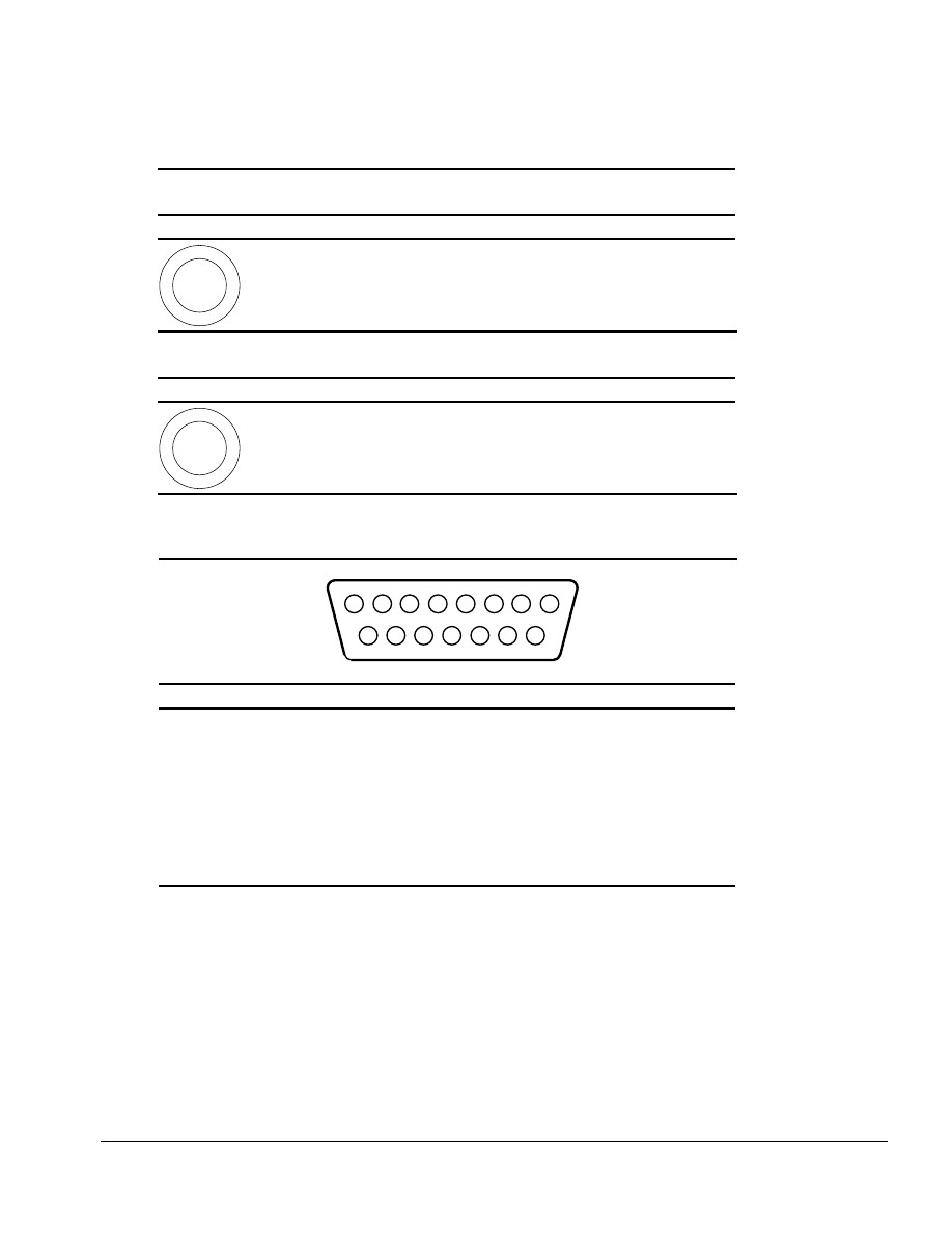
. . . . . . . . . . . . . . . . . . . . . . . . . . . . . . . . . . . . .
Connector Pin Assignments
A-3
Table A-7
Stereo Line-out Jack
Connector
Pin
Signal
1
2
1
2
Audio out
Ground
Table A-8
Stereo Line-in Jack
Connector
Pin
Signal
1
2
1
2
Audio in
Ground
Table A-9
MIDI/JoystickConnector
(ArmadaStation only)
2
1
3
4
6
5
9
8
10
11
12
13
15
14
7
Pin
Signal
Pin
Signal
1
Ground
9
Ground
2
Joystick Button
10
Joystick Button
3
Joystick Direction
11
Joystick Direction
4
Ground
12
MIDI Out
5
Ground
13
Joystick Direction
6
Joystick Direction
14
Joystick Button
7
Joystick Button
15
MIDI In
8
Ground
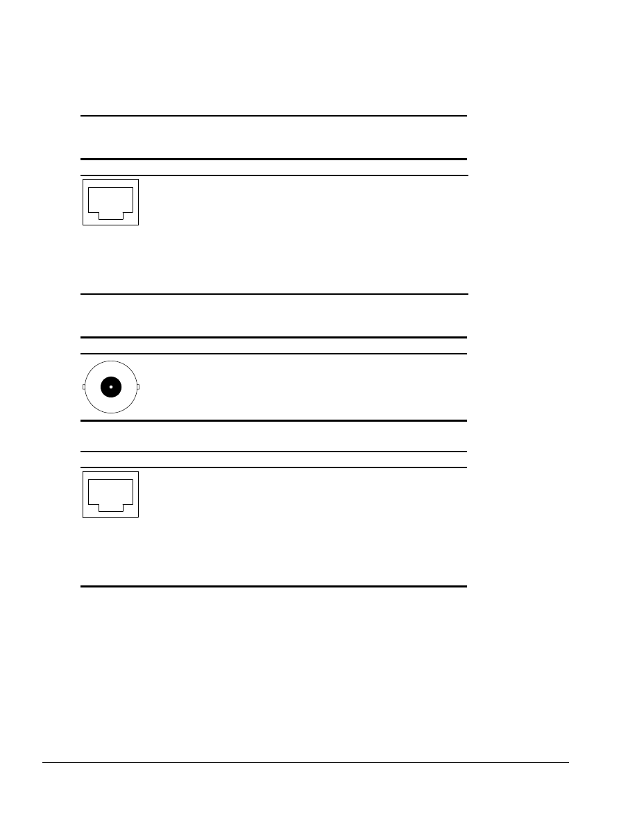
. . . . . . . . . . . . . . . . . . . . . . . . . . . . . . . . . . . . .
A-4
Connector Pin Assignments
Table A-10
Modem RJ-11 Jack
(North America, Latin America, Japan, and Hong Kong modem models)
Connector
Pin
Signal
6
5
4
3
2
1
7
8
1
2
3
4
5
6
7
8
NC_J3A
NC_J3B
TIP
RING
NC_J3C
NC_J3D
Unused
Unused
Table A-11
Ethernet BNC Connector
(Europe, Middle East, Africa, and Asia Pacific models)
Connector
Pin
Signal
1 (Inside)
2 (Outside)
Data
Ground
Table A-12
Ethernet RJ-45 Jack
Connector
Pin
Signal
6
5
4
3
2
1
7
8
1
2
3
4
5
6
7
8
(+) Transmit Data
(-) Transmit Data
(+) Receive Data
Unused
Unused
(-) Receive Data
Unused
Unused

. . . . . . . . . . . . . . . . . . . . . . . . . . . . . . . . . . . . .
Connector Pin Assignments
A-5
Table A-13
Docking Connector
Pin
Signal
Pin
Signal
1
EBOXL
34
XA1/R OUT
2
AGND
35
GND
3
EBOXS1
36
GND
4
RED
37
EXPCLK2
5
AGND
38
+3.3V
6
GREEN
39
EXPCLK0
7
AGRD
40
+5V (8051VCC)
8
BLUE
41
EXPCLK
9
AGND
42
EBOXS2
10
VSYNC
43
GND
11
HSYNC
44
EBOXL
12
DDC DAT
45
EBOXL /GND
13
DDC CLK
46
SRDY
14
GND
47
EBOXS1 /GND
15
INDEX
48
RI1 EX
16
RDATA
49
GND
17
TRK0
50
SLCT LD0
18
WDATA
51
PE LD1
19
WGATE
52
ACK LD2
20
STEP
53
BUSY LD3
21
DIR
54
GND
22
POWER ON
55
STRB LD4
23
SYS RESET
56
ALF LD5
24
GND
57
INIT LD6
25
DSKCHG
58
SLCTIN LD7
26
+5 V (VDD)
59
GND
27
AUGND
60
PDATA0 LD8
28
XA2/L IN
61
PDATA1 LD9
29
XA3/R IN
62
PDATA2 LD10
30
MID0/MIC IN
63
PDATA3 LD11
31
AUGND
64
GND
32
XA0/L OUT
65
PDATA4 LD12
33
XSD/MIC SN
66
PDATA5 LD13
Continued

. . . . . . . . . . . . . . . . . . . . . . . . . . . . . . . . . . . . .
A-6
Connector Pin Assignments
Table A-13
Continued
Pin
Signal
Pin
Signal
67
PDATA6 LD14
105
AD[16]
68
PDATA7 LD15
106
GND
69
GND
107
AD[15]
70
ERROR LCLK
108
AD[13]
71
RXD1 LVREQ
109
AD[11]
72
TXD1 LCREQ
110
AD[09]
73
RTS1 LEN
111
GND
74
GND
112
AD[06]
75
CTS1 LIIC CLK
113
AD[04]
76
DTR1 LIIC DAT
114
AD[02]
77
DSR1 EX
115
AD[00]
78
DCD1 EX
116
GND
79
12C DATA
117
FRAME
80
GND
118
TRDY
81
12C CLK
119
STOP
82
GND
120
PAR
83
HDSEL
121
CBE0
84
GND
122
CBE1
85
WPROT
123
GND
86
EBOXS2 /GND
124
KB CLK
87
ERDY
125
RSVD1/M CTRL2
88
EBOXL /GND
126
XSC/L OUT SN
89
FLUSHREQ
127
RSVD2/M OFF HOOK
90
MEMACK
128
KB DATA
91
PS2 VCC
129
MGND
92
SERIRQ
130
STANDBY
93
PS2 CLK
131
M DRZP
94
EXPREQ
132
M DRXN
95
AD[29]
133
VBATT
96
AD[31]
134
EXPGNT
97
AD[30]
135
VBATT
98
AD[28]
136
GND
99
AD[26]
137
VBATT
100
GND
138
PS2 DATA
101
AD[24]
139
VBATT
102
AD[22]
140
AD[25]
103
AD[20]
141
VBATT
104
AD[18]
142
AD[27]
Continued

. . . . . . . . . . . . . . . . . . . . . . . . . . . . . . . . . . . . .
Connector Pin Assignments
A-7
Table A-13
Continued
Pin
Signal
Pin
Signal
143
VBATT
160
CBE3
144
AD[23]
161
CBE2
145
GND
162
IRDY
146
AD[21]
163
DEVSEL
147
AD[19]
164
LOCK
148
AD[17]
165
OERR
149
GND
166
SERR
150
AD[14]
167
GND
151
AD[12]
168
RSVD3
152
AD[10]
169
M 12C CLK
153
AD[08]
170
M 12C DATA
154
GND
171
M RING
155
AD[07]
172
MGND
156
AD[05]
173
M DXTN
157
AD[03]
174
GND
158
AD[01]
175
M DXTP
159
GND
176
MSTRBAT

Connector Pin Assignments
A-8

. . . . . . . . . . . . . . . . . . . . . . . . . . . . . . . . . . . . .
Appendix B
Power Cord Set Requirements
B-1
Power Cord Set Requirements
3-Conductor Power Cord Set
The wide range input feature of the Compaq ArmadaStation and Armada MiniStation
permit them to operate from any line voltage from 100 to 120 or 220 to 240 volts AC.
The power cord sets received with the ArmadaStation and Armada MiniStation meet the
requirements for use in the country where the equipment is purchased.
Power cord sets for use in other countries must meet the requirements of the country
where the ArmadaStation and Armada MiniStation are used. For more information on
power cord set requirements, contact a Compaq authorized reseller or service provider.
General Requirements
The requirements listed below are applicable to all countries:
1. The length of the power cord set must be at least 5.00 feet (1.5 m) and a maximum of
6.50 feet (2.0 m).
2. All power cord sets must be approved by an acceptable accredited agency
responsible for evaluation in the country where the power cord set will be used.
3. The power cord set must have a minimum current capacity of 10A and a nominal
voltage rating of 125 or 250 volts AC, as required by each country’s power system.
4. The appliance coupler must meet the mechanical configuration of an EN 60 320/IEC 320
Standard Sheet C13 connector, for mating with appliance inlet on the back of the
ArmadaStation and Armada MiniStation.

. . . . . . . . . . . . . . . . . . . . . . . . . . . . . . . . . . . . .
B-2
Power Cord Set Requirements
Country-Specific Requirements
3-Conductor Power Cord Set Requirements—By Country
Country
Accredited Agency
Applicable Note Numbers
Australia
EANSW
1
Austria
OVE
1
Belgium
CEBC
1
Canada
CSA
2
Denmark
DEMKO
1
Finland
FIMKO
1
France
UTE
1
Germany
VDE
1
Italy
IMQ
1
Japan
JIS
3
The Netherlands
KEMA
1
Norway
NEMKO
1
Sweden
SEMKO
1
Switzerland
SEV
1
United Kingdom
BSI
1
United States
UL
2
Notes
1. The flexible cord must be <HAR> Type HO5VV-F, 3-conductor, 1.0 mm
2
conductor size. Power cord set fittings (appliance coupler and wall plug) must bear
the certification mark of the agency responsible for evaluation in the country where it
will be used.
2. The flexible cord must be Type SPT-3 or equivalent, No. 18 AWG, 3-conductor. The
wall plug must be a two-pole grounding type with a NEMA 5-15P (15A, 125V) or
NEMA 6-15P (15A, 250V) configuration.
3. The appliance coupler, flexible cord, and wall plug must bear a "T" mark and
registration number in accordance with the Japanese Dentori Law. The flexible cord
must be Type VCT or VCTF, 3-conductor, 0.75mm
2
conductor size. The wall plug
must be a two-pole grounding type with a Japanese Industrial Standard C8303
(15A, 125V) configuration.

. . . . . . . . . . . . . . . . . . . . . . . . . . . . . . . . . . . . .
Index
I-1
INDEX
A
AC power
cord
3-conductor, B-1
requirements, B-1
activity lights
Armada MiniStation, 1-16
ArmadaStation, 1-8
additional information, x
alignment
guides
ArmadaStation
illustrated, 1-4
tray
ArmadaStation
illustrated, 3-2
installing on
ArmadaStation, 5-7
removing from
ArmadaStation, 5-6
altitude
Armada MiniStation, 7-2
ArmadaStation, 7-1
Armada 7000 Hard Drive
MultiBay Adapter
illustrated, 3-12
option part number, 3-13
sparepart number, 3-13
Armada 7000 Half-Height
MultiBay Adapter
illustrated, 3-2, 3-12
option part number, 3-13
spare part number, 3-3,
3-13
Armada MiniStation
components, 3-8
left side, 1-14
rear panel, 1-15
right side, 1-13
spare part numbers, 3-9
top, 1-13
depth, 7-2
disassembly sequence chart,
6-2
disconnecting power, 6-3
documentation, 3-7, 3-16
external components, 6-4
external connectors, 1-15
height, 7-2
Illustrated Parts Map
spare part number, 3-7,
3-16
Installation and Operations
Guide
spare part number, 3-7,
3-16
Maintenance and Service
Guide
spare part number, 3-7,
3-16
miscellaneous base
hardware kit
illustrated, 3-5
spare part number, 3-5
miscellaneous base
plastics kit
illustrated, 3-4
spare part number, 3-4
miscellaneous
enclosures kit
illustrated, 3-10
spare part number, 3-10
miscellaneous plastics kit
illustrated, 3-11
spare part number, 3-11
options
illustrated, 3-14
option part numbers, 3-15
spare part numbers, 3-15
preparing for disassembly,
6-3
removal and replacement
procedures, 6-1
serial number, 6-1
specifications, 7-2
Armada MiniStation E
weight, 7-2
Armada MiniStation EX
weight, 7-2
ArmadaStation
components, 1-4, 3-3
front side, 1-4, 1-5
illustrated, 3-2
left side, 1-6
rear panel, 1-6
right side, 1-4, 1-5
spare part numbers, 3-3
top side, 1-4
depth, 7-1
disassembly sequence chart,
5-2
documentation, 3-7, 3-16
external components, 5-4
external connectors
rear panel, 1-7
right side, 1-7
height, 7-1
Illustrated Parts Map
spare part number, 3-7,
3-16
Installation and Operations
Guide
spare part number, 3-7,
3-16
Maintenance and Service
Guide
spare part number, 3-7,
3-16
miscellaneous base
hardware kit
illustrated, 3-5
spare part number, 3-5
miscellaneous base
plastics kit
illustrated, 3-4
spare part number, 3-4
miscellaneous cable kits
illustrated, 3-6
spare part number, 3-7
MultiBay Option Cable Kit
illustrated, 3-6
spare part number, 3-7
MultiBay/PC Card
Assembly
illustrated, 3-12
spare part number, 3-13
options, 3-14
option part numbers, 3-15
spare part numbers, 3-15

. . . . . . . . . . . . . . . . . . . . . . . . . . . . . . . . . . . . .
I-2 Index
preparing for disassembly,
5-3
removal and replacement
procedures, 5-1
serial number, 5-1
specifications, 7-1
weight, 7-1
width, 7-1
audio bass port
ArmadaStation
illustrated, 1-6
B
backplane assembly
ArmadaStation
illustrated, 3-2
removing from
ArmadaStation, 5-57
base assembly
ArmadaStation
illustrated, 3-2
spare part number, 3-3
battery
charging bay
Armada MiniStation EX
illustrated, 1-13
charging bay door
Armada MiniStation EX
illustrated, 3-11
charging light
Armada MiniStation EX,
1-16
illustrated, 1-13
BNC connector
Armada MiniStation
illustrated, 1-15
ArmadaStation
illustrated, 1-7
regional availability, 1-10
pinout, A-4
C
C/U actuator
assembly, 5-49
component of control
panel assembly, 5-40
tripping in ArmadaStation,
5-46
CD-ROM/audio cable
ArmadaStation
illustrated, 3-2, 3-6
connecting to backplane
assembly, 5-31
connecting to half-height
MultiBay adapter, 5-31
Compaq logo
installing on Armada
MiniStation, 6-4
installing on
ArmadaStation, 5-4
components
ArmadaStation, 1-4
computer eject button
ArmadaStation
illustrated, 1-5
connector pin assignments,
A-1
control panel
assembly
ArmadaStation
illustrated, 3-2
spare part number, 3-3
installing in
ArmadaStation, 5-44
removing from
ArmadaStation, 5-40
board
component of control
panel assembly, 5-40
cable
ArmadaStation
illustrated, 3-2, 3-6
disconnecting from
backplane assembly,
5-39
Kit
illustrated, 3-6
spare part number, 3-7
removing from
ArmadaStation, 5-39
routing in ArmadaStation,
5-47
current
Armada MiniStation, 7-2
ArmadaStation, 7-1
D
depth measurement
Armada MiniStation, 7-2
ArmadaStation, 7-1
disassembly sequence chart
Armada MiniStation, 6-2
ArmadaStation, 5-2
disconnecting power
Armada MiniStation, 6-3
ArmadaStation, 5-3
diskette drive
cable
ArmadaStation
illustrated, 3-2, 3-6
connecting to the
half-height MultiBay
adapter, 5-28
docking
latch knob
Armada MiniStation
illustrated, 3-8, 3-11
troubleshooting, 2-2
docking connector
Armada MiniStation
illustrated, 1-13
ArmadaStation
illustrated, 1-4
pinout, A-5
docking latch
Armada MiniStation
illustrated, 1-13
ArmadaStation
illustrated, 1-4
docking lever
Armada MiniStation
illustrated, 1-13
documentation
Armada MiniStation, 3-7,
3-16
ArmadaStation, 3-7, 3-16
drive cage
ArmadaStation
illustrated, 3-2, 3-5
shield
ArmadaStation
illustrated, 3-2, 3-5

. . . . . . . . . . . . . . . . . . . . . . . . . . . . . . . . . . . . .
Index I-3
drive cage shield
installing on
ArmadaStation, 5-15
removing from
ArmadaStation, 5-14
E
eject button
component of control panel
assembly, 5-40
eject/keylock button
Armada MiniStation EX
illustrated, 1-13
enclosure cover
Armada MiniStation
illustrated, 3-8
removing from Armada
MiniStation, 6-6
environmental specifications
Armada MiniStation, 7-2
ArmadaStation, 7-1
Ethernet
regional differences
Armada MiniStation, 1-17
ArmadaStation, 1-10
troubleshooting, 2-3
expansion board
installing in ArmadaStation,
5-50
troubleshooting:, 2-3
expansion card cage
ArmadaStation
illustrated, 3-2, 3-4
removing from
ArmadaStation, 5-59
expansion slot cover
removing from
ArmadaStation, 5-50
external components
Armada MiniStation, 6-4
ArmadaStation, 5-4
external keyboard connector
Armada MiniStation
illustrated, 1-15
ArmadaStation
illustrated, 1-7
pinout, A-2
external monitor connector
Armada MiniStation
illustrated, 1-15
ArmadaStation
illustrated, 1-7
pinout, A-2
external mouse connector
Armada MiniStation
illustrated, 1-15
ArmadaStation
illustrated, 1-7
pinout, A-2
F
fan
Armada MiniStation
illustrated, 1-15
ArmadaStation
illustrated, 1-6
features
Armada MiniStation, 1-11
ArmadaStation, 1-1
feet
installing on Armada
MiniStation, 6-5
installing on
ArmadaStation, 5-5
H
half-height
bays, 5-16
ArmadaStation, 1-8
illustrated, 1-4
blank bezel cover
ArmadaStation
illustrated, 3-2, 3-4
removing from
ArmadaStation drive
cage, 5-17
drive
installing on
ArmadaStation, 5-16
removing from
ArmadaStation, 5-16
half-height MultiBay
adapter, 5-16
installing on
ArmadaStation, 5-22
removing from
ArmadaStation, 5-22
hard drive
cable
ArmadaStation
illustrated, 3-2, 3-6
connecting to backplane
assembly, 5-29
connecting to half-height
MultiBay adapter, 5-29
headphone jack
ArmadaStation
illustrated, 1-7
pinout, A-1
headset
illustrated, 3-14
option part number, 3-15
spare part number, 3-15
height measurement
Armada MiniStation, 7-2
ArmadaStation, 7-1
humidity
Armada MiniStation, 7-2
I
I/O assembly
ArmadaStation
illustrated, 3-2
spare part number, 3-3
installing on
ArmadaStation, 5-34
removing from
ArmadaStation, 5-31
illustrated parts catalog, 3-1
Illustrated Parts Map
ArmadaStation and Armada
MiniStation
spare part number, 3-7,
3-16
information
locating additional, x

. . . . . . . . . . . . . . . . . . . . . . . . . . . . . . . . . . . . .
I-4 Index
infrared
lens
component of control
panel assembly, 5-40
port
ArmadaStation
illustrated, 1-5
transceiver
connector
illustrated, 1-15
illustrated, 3-14
option part number, 3-15
spare part number, 3-15
infrared transceiver
connector
ArmadaStation
illustrated, 1-7
Installation and Operations
Guide
ArmadaStation and Armada
MiniStation
spare part number, 3-7,
3-16
ISA expansion board
ArmadaStation, 1-10
installation, 5-50
location, 5-51
installing in ArmadaStation,
5-50
J
joystick connector
ArmadaStation
illustrated, 1-7
pinout, A-3
K
keyboard connector
pinout, A-2
keylock
ArmadaStation
illustrated, 1-5
L
line frequency
Armada MiniStation, 7-2
ArmadaStation, 7-1
lock
ArmadaStation
spare part number, 3-7
logo
Compaq
installing on Armada
MiniStation, 6-4
installing on
ArmadaStation, 5-4
lower case insert
Armada MiniStation
illustrated, 3-8
spare part number, 3-9
LTE 5000 Half-Height
MultiBay Adapter
illustrated, 3-14
option part number, 3-15
spare part number, 3-15
M
Maintenance and Service
Guide
ArmadaStation and Armada
MiniStation
spare part number, 3-7,
3-16
manual release lever, 5-9
mechanism assembly
ArmadaStation
illustrated, 3-2
spare part number, 3-3
removing from
ArmadaStation, 5-52
microphone jack
Armada MiniStation
illustrated, 1-15
ArmadaStation
illustrated, 1-7
pinout, A-1
MIDI connector
ArmadaStation
illustrated, 1-7
pinout, A-3
miscellaneous base
hardware kit
ArmadaStation, 3-5
spare part number, 3-5
miscellaneous base
plastics kit
ArmadaStation, 3-4
spare part number, 3-4
miscellaneous base screw kit
ArmadaStation
spare part number, 3-7,
Armada MiniStation
spare part number 3-16
miscellaneous cable kit
components
ArmadaStation
illustrated, 3-6
spare part number, 3-7
miscellaneous plastics kit
Armada MiniStation, 3-11
spare part number, 3-1
miscellaneous screws kit
Armada MiniStation
spare part number, 3-16
modem
regional differences
Armada MiniStation, 1-17
ArmadaStation, 1-10
module assembly
alignment pins, 6-10
Armada MiniStation
illustrated, 3-8
spare part number, 3-9
installing on Armada
MiniStation, 6-10
international version
Armada MiniStation
illustrated, 3-8
spare part number, 3-9
removing from Armada
MiniStation, 6-7
monitor connector
pinout, A-2

. . . . . . . . . . . . . . . . . . . . . . . . . . . . . . . . . . . . .
Index I-5
monitor support cover
Armada MiniStation
illustrated, 3-14
maximum weight
supported, 7-2
option part number, 3-15
spare part number, 3-15
weight, 7-2
ArmadaStation
illustrated, 3-2
maximum weight
supported, 7-1
spare part number, 3-3
weight, 7-1
monitor support cover slots
ArmadaStation
illustrated, 1-4
mouse connector
pinout, A-2
MultiBay
activity light
Armada MiniStation EX
illustrated, 1-14
ArmadaStation, 1-8
illustrated, 1-5
Armada MiniStation EX,
1-16
illustrated, 1-14
ArmadaStation, 1-8, 5-16
illustrated, 1-4
cable
ArmadaStation
illustrated, 3-2, 3-6
connecting to half-height
MultiBay adapter, 5-30
device release latch
ArmadaStation
illustrated, 1-4
door
Armada MiniStation EX
illustrated, 3-11
eject button
Armada MiniStation EX
illustrated, 1-14
light
Armada MiniStation EX,
1-16
Option Cable Kit
illustrated, 3-6
spare part number, 3-7
security arm
position in C/U actuator
assembly, 5-49
MultiBay/PC Card Assembly
ArmadaStation
illustrated, 3-12
spare part number, 3-13
removing from Armada
MiniStation, 6-12
mute button
ArmadaStation
illustrated, 1-5
N
network
troubleshooting, 2-3
O
100BaseTX Ethernet
module, 5-31
illustrated, 3-14
installing
ArmadaStation, 5-33
option part number, 3-15
removing jumpers
ArmadaStation, 5-33
spare part number, 3-15
options
Armada MiniStation, 3-15
option part numbers, 3-15
spare part numbers, 3-15
ArmadaStation, 3-14
option part numbers, 3-15
spare part numbers, 3-15
P
parallel connector
Armada MiniStation
illustrated, 1-15
ArmadaStation
illustrated, 1-7
pinout, A-1
PC Card
doors
Armada MiniStation EX
illustrated, 3-11
security post
ArmadaStation
illustrated, 1-5
slots
Armada MiniStation EX,
1-17
illustrated, 1-13
ArmadaStation, 1-9
illustrated, 1-5
PCI expansion board
ArmadaStation, 1-10
installation, 5-50
location, 5-51
installing in ArmadaStation,
5-50
PCI/ISA expansion slots
ArmadaStation
illustrated, 1-5
power button
Armada MiniStation
illustrated, 1-14
ArmadaStation
illustrated, 1-5
component of control panel
assembly, 5-40
power cable
disconnecting from Armada
MiniStation, 6-3
disconnecting from
ArmadaStation, 5-56
power connector
Armada MiniStation
illustrated, 1-15
ArmadaStation
illustrated, 1-7
power cord
Armada MiniStation
spare part number, 3-9
ArmadaStation
spare part number, 3-3
power cord set
requirements, B-1

. . . . . . . . . . . . . . . . . . . . . . . . . . . . . . . . . . . . .
I-6 Index
power supply
Armada MiniStation
illustrated, 3-8
spare part number, 3-9
ArmadaStation
illustrated, 3-2
spare part number, 3-3
removing from Armada
MiniStation, 6-11
removing from
ArmadaStation, 5-55
power/suspend light
ArmadaStation, 1-8
illustrated, 1-5
preparing for disassembly
Armada MiniStation, 6-3
ArmadaStation, 5-3
R
rear panel
assembly, 5-8
ArmadaStation
illustrated, 3-2
installing on
ArmadaStation, 5-10
removing from
ArmadaStation, 5-8
release latch, 5-8
ArmadaStation
illustrated, 1-6
shield, 5-8
relative humidity
Armada MiniStation, 7-2
relative humidity (relative)
ArmadaStation, 7-1
removal and replacement
procedures
Armada MiniStation, 6-1
ArmadaStation, 5-1
RJ-11 jack
Armada MiniStation
illustrated, 1-15
ArmadaStation
illustrated, 1-7
regional availability, 1-10
pinout, A-4
RJ-45 jack
Armada MiniStation
illustrated, 1-15
ArmadaStation
illustrated, 1-7
regional availability, 1-10
pinout, A-4
S
screws
miscellaneous kit
Armada MiniStation
spare part number, 3-16
ArmadaStation
spare part number, 3-7
security actuator
position in C/U actuator
assembly, 5-49
positioning in
ArmadaStation, 5-44
security cable slot
Armada MiniStation
illustrated, 1-13
ArmadaStation
illustrated, 1-6
security extension bar
alignment, 5-26
security lock
Armada MiniStation EX,
1-16
ArmadaStation, 1-9
component of control panel
assembly, 5-40
security u-bolt
ArmadaStation
illustrated, 1-6
serial connector
Armada MiniStation
illustrated, 1-15
ArmadaStation
illustrated, 1-7
pinout, A-2
serial number, x
Armada MiniStation, 6-1
illustrated, 1-14
ArmadaStation, 5-1
illustrated, 1-5
shock
Armada MiniStation, 7-2
ArmadaStation, 7-1
speaker
insulator
removing from
ArmadaStation, 5-38
left
ArmadaStation
illustrated, 3-2
spare part number, 3-3
removing from
ArmadaStation, 5-38
right
component of control
panel assembly, 5-40
specifications, 7-1
Armada MiniStation, 7-2
ArmadaStation, 7-1
stereo line-in jack
Armada MiniStation
illustrated, 1-15
ArmadaStation
illustrated, 1-7
pinout, A-3
stereo line-out jack
Armada MiniStation
illustrated, 1-15
ArmadaStation
illustrated, 1-7
pinout, A-3
stereo speakers
ArmadaStation
illustrated, 1-4
suspend
button
ArmadaStation
illustrated, 1-5
component of control
panel assembly, 5-40
lightpipe
component of control
panel assembly, 5-40

. . . . . . . . . . . . . . . . . . . . . . . . . . . . . . . . . . . . .
Index I-7
T
25-pin connector
Armada MiniStation
illustrated, 1-15
technician notes, ix
temperature
Armada MiniStation, 7-2
ArmadaStation, 7-1
top brace
ArmadaStation
illustrated, 3-2, 3-5
installing on
ArmadaStation, 5-37
removing from
ArmadaStation, 5-35
torsion spring
position in C/U actuator
assembly, 5-49
tower stand
ArmadaStation
illustrated, 3-14
option part number, 3-15
spare part number, 3-15
troubleshooting, 2-1
docking, 2-2
Ethernet, 2-3
expansion board, 2-3
network, 2-3
undocking, 2-2
Twenty-five-pin connector
ArmadaStation
illustrated, 1-7
regional availability, 1-10
U
undocking
troubleshooting, 2-2
upper case assembly
ArmadaStation
illustrated, 3-2
spare part number, 3-3
installing on
ArmadaStation, 5-13
removing from
ArmadaStation, 5-11
V
vibration
Armada MiniStation, 7-2
ArmadaStation, 7-1
voltage
Armada MiniStation, 7-2
ArmadaStation, 7-1
voltage selector switch
Armada MiniStation
illustrated, 1-15
ArmadaStation
illustrated, 1-6
volume control
ArmadaStation
illustrated, 1-5
volume/mute button
component of control panel
assembly, 5-40
W
weight
Armada MiniStation E, 7-2
Armada MiniStation EX,
7-2
ArmadaStation, 7-1
monitor support cover
Armada MiniStation, 7-2
ArmadaStation, 7-1
width measurement
Armada MiniStation, 7-2
ArmadaStation, 7-1

. . . . . . . . . . . . . . . . . . . . . . . . . . . . . . . . . . . . .
I-8 Index
Document Outline
- Contents
- Preface
- Ch 1 Product Description
- Ch 2 Troubleshooting
- Ch 3 Illustrated Parts Catalog
- Ch 4 Removal and Replacement Preliminaries
- Ch 5 ArmadaStation Removal and Replacement Procedures
- Ch 6 Armada MiniStation Removal and Replacement Procedures
- Ch 7 Specifications
- App A Connector Pin Assignments
- App B Power Cord Set Requirements
- Index
Wyszukiwarka
Podobne podstrony:
Lecture11 Stations
Stationery 1 What is this Worksheet
Notatki wykład Armada
Stalnov Chernaya Armada 2 Emissar chyornoy Armady 386048
7 stationary gas systems eng
Fading Suns The Haunting of Derelict Station
4 AT THE STATION
MICRO HYDRO POWER STATION
The main press station is installed in the start shaft and?justed as to direction
Outlook Stationery Letterheads And Templates Using Signatures
filling station information
Armada notatki, filozofia chsześcijańska
stationery 2 what is this worksheet
iTNC Programming Station
Clock and Weather Station
NFPA 20 (2003) Stationary Pumps for Fire Protection
Lecture11 Stations
więcej podobnych podstron