Adam Paweł Zaborski
Project “The development of the didactic potential of Cracow University of Technology in the range of
modern construction” is co-financed by the European Union within the confines of the European Social Fund
and realized under surveillance of Ministry of Science and Higher Education.
2.
Geometric stability (rigidity)
Introduction
Definitions
degrees of freedom (DOF) – a number of independent parameters that describe the movement of the
structure
mechanism – a structure with at least one DOF
bar – an element with length much greater than two other dimensions
shield – a set of elements rigidly linked (reciprocal movements of all elements are excluded); from the
kinematic point of view, a shield can be considered as a bar and vice versa
hinge – a connection that can be considered as a connection by two bars pinned at the point
virtual velocity – a velocity consistent with imposed constraints
virtual displacement – a displacement consistent with virtual velocity (the same direction and sense)
instantaneous centre of rotation (ICR) – a centre of rotation following the virtual displacements
geometric rigidity – a rigidity of the whole structure
free-body geometric rigidity – a rigidity of the structure considered in isolation from constraints (internal or
local rigidity)
Theorems
A shield has only one ICR.
If two points of a shield are immobilized, the whole shield is immobilized.
(Two shields theorem, 2ST)
The rigid connection between two shields consists in the connection by three bars, the direction of which
don’t intersect at one point (including so-called improper point – at infinity)
Instead of three bars, the connection of two shields may consists in one hinge and one bar not passing by
the hinge.
(Three shields theorem, 3ST)
The rigid connection of three shields consists in the connection of each pair of shields by one hinge and
these hinges are not collinear.
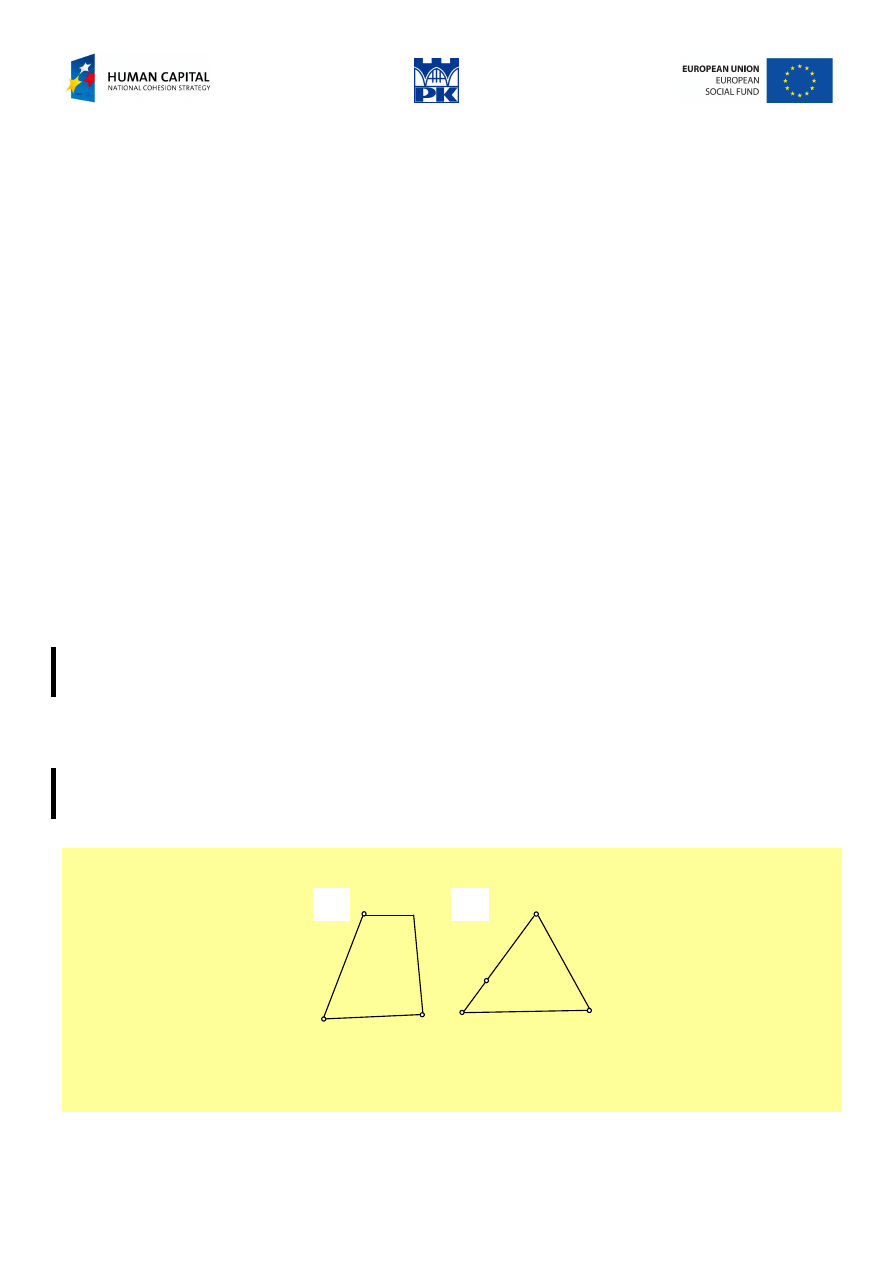
It means that the connection “in triangle” is geometrically rigid.
Note! In fact this means a connection of three elements, not the shape of the set (see Fig. 2.1).
a)
b)
Fig. 2.1 a) the quadrangle shape made of three elements is geometrically rigid,
b) the triangular shape made of four elements is not geometrically rigid
Unfortunately, in English (as well as in Polish) there is no such word as “three-lateral”.
Adam Paweł Zaborski
Project “The development of the didactic potential of Cracow University of Technology in the range of
modern construction” is co-financed by the European Union within the confines of the European Social Fund
and realized under surveillance of Ministry of Science and Higher Education.
(Virtual velocities theorem, VVT)
A structure is geometrically rigid if and only if there is no consistent field of virtual velocities.
The opposite theorem is also valid.
To prove that the whole structure is rigid, it should be proved that every point of the structure is blocked
(unmovable).
Methods to determine geometric rigidity
The use of two or three shields theorem is easy but not always effective. The theorem of virtual velocities
is always effective, but – usually – not the easiest, because it should be proved for all elements of a
structure considered.
Usually we proceed in two steps: free-body rigidity and rigidity of the whole structure (overall rigidity).
Each step of analysis is important and may be fruitful.
The analysis of free-body rigidity suggests the way of reactions calculation. Free-body stiff structure means
(there will be) no problem with reactions calculation. Free body unstable system usually requires some
particular effort: hinge equation (zero hinge’s moment), additional intersections and so on. In extreme
cases reaction calculation may be very difficult.
The rigidity of the whole structure is needed for static calculations. The mechanisms (the structures
unstable) should be analyzed dynamically, with the use of inertia (d’Alembert’s) forces.
Although in particular cases unstable structures can be solved by static equations only, we deliberately
limit scope of static considerations to the problems with zero (or less) DOF.
If the rigidity of some subset is proved we may replace it by a shield in the sequel.
Example
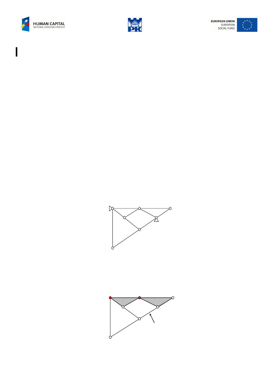
Let’s determine geometric stability of the structure from the figure below:
Fig. 2.2 The structure considered
Solution by 3 shields theorem
1.
We determine the free-body rigidity
(1,3)
(1,2)
3
2
1
one bar only
Fig. 2.3 Free-body rigidity
Adam Paweł Zaborski
Project “The development of the didactic potential of Cracow University of Technology in the range of
modern construction” is co-financed by the European Union within the confines of the European Social Fund
and realized under surveillance of Ministry of Science and Higher Education.
We detect two sets “in triangle” – there are two shields. Using the theorem of three shields we find that the
free-body structure is not rigid: one bar is missing between the shields 1 and 3.
2.
We determine the whole structure rigidity
(2,3)
(1,3)
(1,2)
2
1
3
Fig. 2.4 Overall rigidity of the structure
We detect three shields (one of them is the bedrock) which are correctly connected: three hinges of
connection are not collinear, so they are blocked.
2
3
1
2
3
1
Fig. 2.5 Overall rigidity of the structure, cont.
We find three shields properly connected (Fig. 2.5 from the left) and next – considering the rigid subset as
a shield – we come to the same conclusion once more (the Fig. 2.5 from the right). In this way we make
certain that all elements of the structure are immobilized.
This authorizes us to claim that the structure is free-body unstable and entirely (it means with constraints)
stable.
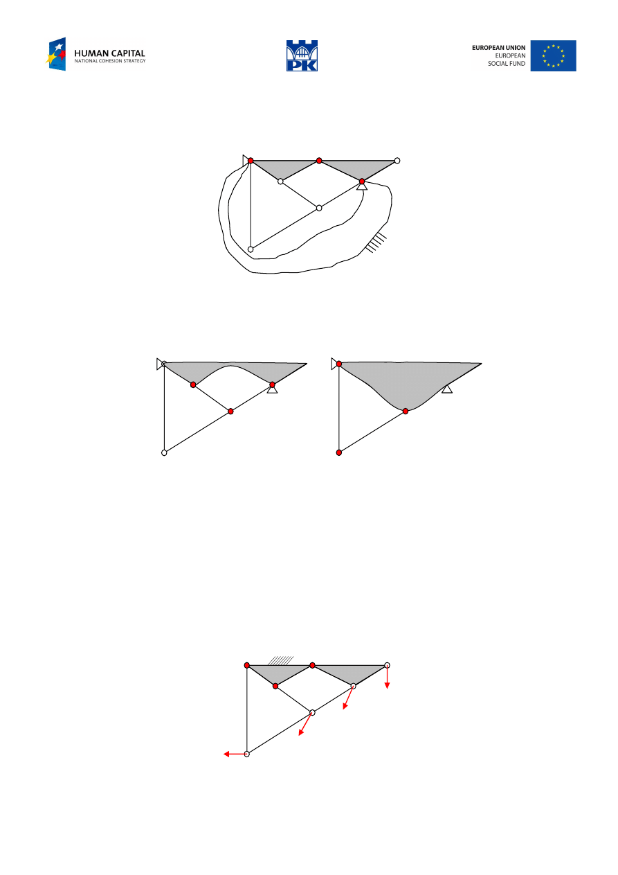
The solution by virtual velocities method
For free-body rigidity, we start with the three-laterals, one of them tentatively immobilized. The points of
the blocked shield are ICR of adjacent bars and the shield. There is no contradiction in given velocities
sketch so movement is possible.
Fig. 2.6. Free-body rigidity by VV method
Adam Paweł Zaborski
Project “The development of the didactic potential of Cracow University of Technology in the range of
modern construction” is co-financed by the European Union within the confines of the European Social Fund
and realized under surveillance of Ministry of Science and Higher Education.
For the whole structure rigidity, we consider two ICRs at the pins. Two different velocities result at the
point of two shields’ connection. This contradiction vanishes if and only if both velocities are zero, so the
point should be fixed, see Fig. 2.7
Fig. 2.7 Contradiction at the connection point
Repeating the reasoning, as successive figure 2.8 show, we find the rigidity of the whole structure.
Fig. 2.8 Contradictions at next points
The conclusion is the same as before: the structure is free-body unstable and stable as a whole.
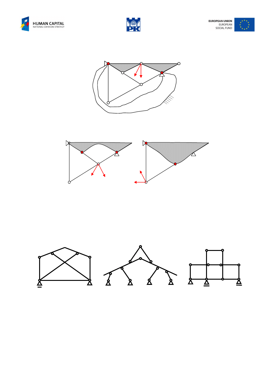
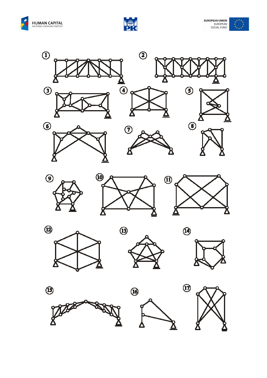
Workshop theme
For the structures below, determine their stability using known methods, but one for each reasoning (using
2ST only, 3ST only and VVT only, 3×3 = 9 solutions for free-body stability and, similarly 9 solutions for
the stability of the entire structures).
a)
b)
c)
Fig. 2.9 Free-body and overall stability problems
Adam Paweł Zaborski
Project “The development of the didactic potential of Cracow University of Technology in the range of
modern construction” is co-financed by the European Union within the confines of the European Social Fund
and realized under surveillance of Ministry of Science and Higher Education.
Review problems
Fig. 2.10 Free-body and overall stability review problems.
Adam Paweł Zaborski
Project “The development of the didactic potential of Cracow University of Technology in the range of
modern construction” is co-financed by the European Union within the confines of the European Social Fund
and realized under surveillance of Ministry of Science and Higher Education.
Addendum
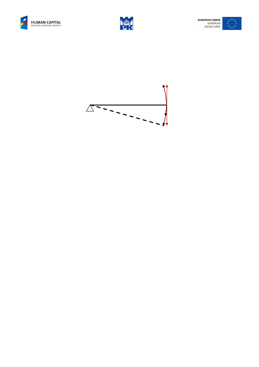
Displacements
There are three different kinds, see the figure below:
−
real (true), calculated or measured,
−
allowed (possible), that may be anticipated
−
virtual, that agree with virtual velocities directions.
VD
AD
TD
AD
VD
(ICR)
Fig. 2.11 Displacement: true, possible and virtual
Looking at Fig. 2.9, some people think that the virtual displacement – as an approximation of the real
displacement – should be infinitesimal (sufficiently small), especially as the real displacements in civil
engineering are close to infinitesimal. It is not true: it is not an approximation and its order is arbitrary (and
may be finite).
Glossary
“geometric rigidity”, mechanical stability – geometryczna niezmienność
(Visibly, there is no English equivalent. Common use of “rigidity” or “stability” might be misleading. Both
words have a different meaning in structural mechanics. “Rigidity”, as opposite to flexibility, means
“hardly flexible” or “stiff”. “Stability” is connected with loss of stability – sudden and very dangerous
phenomena (which will be considered in the second semester of our course)
free-body rigidity – geometryczna niezmienność wewnętrzna
(the whole structure, overall) rigidity – geometryczna niezmienność (zewnętrzna, całości)
bar – pręt
hinge – przegub
shield – tarcza
instantaneous centre of rotation (ICR) – chwilowy środek obrotu
bedrock – ostoja
Wyszukiwarka
Podobne podstrony:
C07 design 02 AZ
C07 design 11 AZ
C07 design 12 AZ
C07 design 08 AZ
C07 design 03 AZ
C07 design 09 az
C07 design 05 AZ
C07 design 10 AZ
C07 design 06 AZ
C07 design 01 AZ
C07 design 03 AZ
C07 design 09 AZ
C07 design 10 AZ
C07 design 01 AZ
C07 design 06 AZ
C07 design 08 AZ
C07 design 15 AZ
C07 design 14 AZ
C07 design 13 AZ
więcej podobnych podstron