Adam Paweł Zaborski
Project “The development of the didactic potential of Cracow University of Technology in the range of
modern construction” is co-financed by the European Union within the confines of the European Social Fund
and realized under surveillance of Ministry of Science and Higher Education.
11. Trusses
Introduction
Definitions
truss – a structure made of straight bars, joined by hinges (without friction), loaded by point forces at
hinges only
truss bar – an element of a truss: a straight bar with the hinges at its ends, all loads are applied at the joints;
there is neither the point moment load nor continuous loading
Design economy
To demonstrate the design economy let’s consider the Eiffel Tower which stands 324 meters tall. If the
whole metal structure were melted down, it would fill the 125-meter square base to the depth of ... 6 cm
only.
Cross-section forces set
Contrary to the frames, where each bar has the cross-section forces given by three different functions, all
trusses’ bars have only one constant axial force.
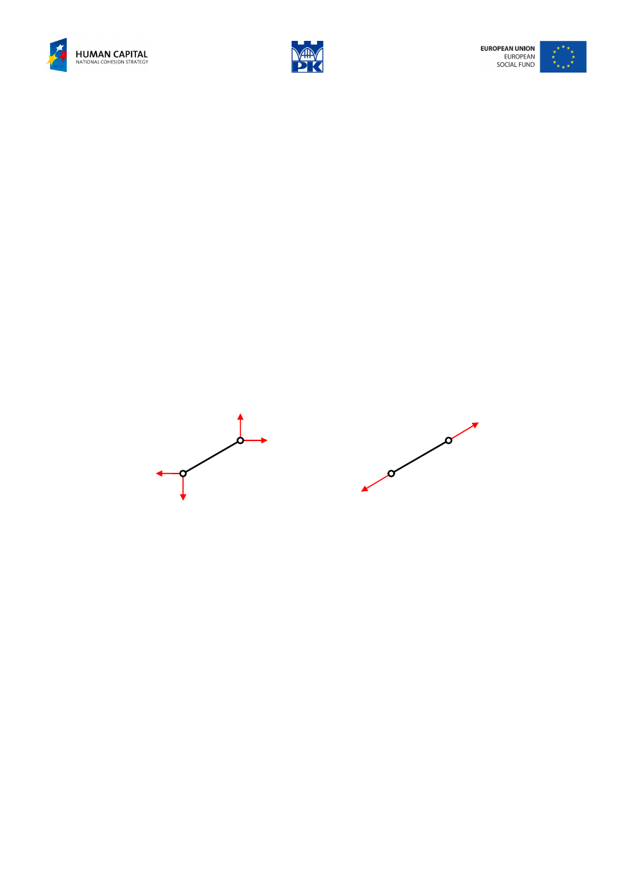
This can be proved easily considering a truss bar free-body balance, in Fig. 11.1.
R
R
V
1
H
1
H
2
V
2
⇒
Fig. 11.1 Free-body balance of a truss bar
At the hinged ends there is no moment. The free-body balance needs the resultant forces at the ends to pass
through the opposite hinge. It means that the resultants have the same directions as the bar, therefore,
bending moment and shear force are identically equal zero and axial force is constant. The two forces are
applied at the ends of the member and are necessarily equal, opposite and collinear for equilibrium. Hence
the English name: two-force members.
Note: Due to design peculiarity (explained later on), the sign of the axial force is more important than its
value and should be clearly indicated.
It will be assumed that sign “plus” means tension and “minus” means compression of the bar. Otherwise,
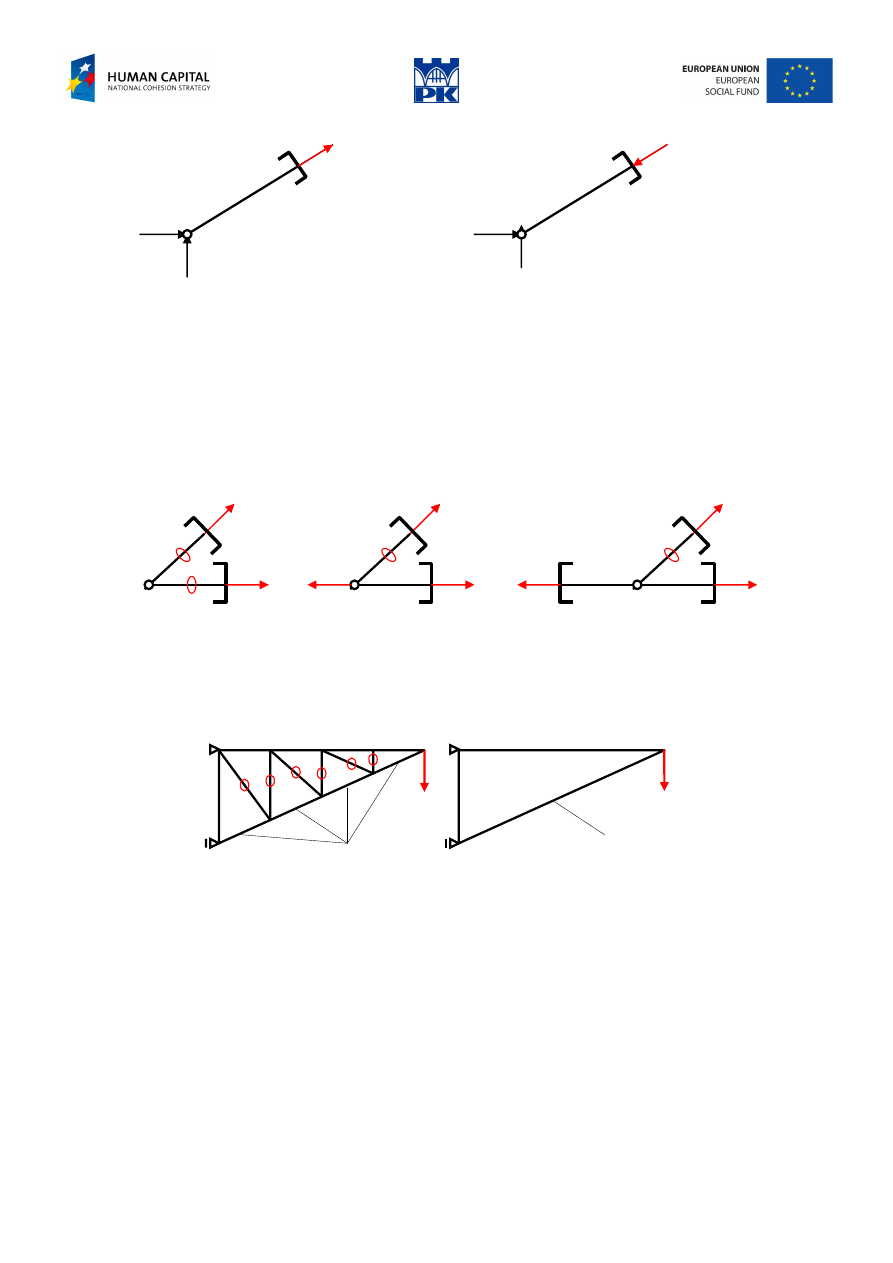
each time the axial force sign would have to be cleared up by words, cf. Fig. 11.2.
Tip: When you use cross-section force sense consistently with the outward normal, no clarification is
needed.
Adam Paweł Zaborski
Project “The development of the didactic potential of Cracow University of Technology in the range of
modern construction” is co-financed by the European Union within the confines of the European Social Fund
and realized under surveillance of Ministry of Science and Higher Education.
N
1
N
1
= – 15 kN
N
1
N
1
= 15 kN (
compression)
Fig. 11.2 Sign of axial force – the convention
Tip: If there is no doubt, the hinges can be omitted in the static scheme drawing.
Theorems of zero force members (ZFMT)
1. Two truss bars connected at a hinge which is not loaded are zero force members.
2. If two truss bars are connected at a hinge which is loaded in the direction of one bar, the second bar is a
zero force member.
3. If three truss bars are connected at a hinge which is not loaded and two of them are collinear, then the
third bar is a zero force member.
Fig. 11.3 Theorems of zero force members
Tip: The analysis of truss begins with the theorems of zero force members.
The zero force members use is needed for reasons of mechanical or element stability. In Fig. 11.4, the
triangular cantilever has several zero force bars “supporting” lower (compressed) strut.
one long (compressed) strut
four short struts
Fig. 11.4 Use of zero force bars
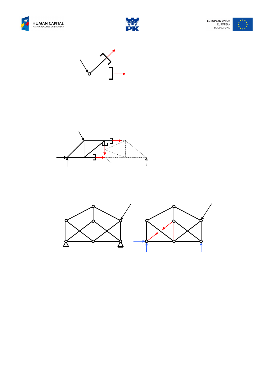
Method of joints
The method consists of isolating each joint of the framework in the form of a free-body diagram and then,
by considering equilibrium at each of these joints, the forces in the members of the framework can be
determined; before analyzing each joint, it should be ensured that each joint does not have more than two
unknown forces.
Adam Paweł Zaborski
Project “The development of the didactic potential of Cracow University of Technology in the range of
modern construction” is co-financed by the European Union within the confines of the European Social Fund
and realized under surveillance of Ministry of Science and Higher Education.
P
N
1
N
2
2
1
,
0
0
N
N
Y
X
→
=
=
∑
∑
Fig. 11.5 Joints method
Note: There are only two independent balance equations for convergent forces set.
Ritter method
The method consists in a section through three bars whose axial forces are unknown and can be determined
from the balance equations.
O
1
N
1
N
2
N
3
O
2
3
2
1
2
1
,
,
0
0
0
N
N
N
Y
O
O
→
=
=
=
∑
∑
∑
Fig. 11.6 Section method
Henneberg’s method (of bar conversions)
e
X
X
Fig. 11.7 Bar exchange
We replace one bar by its axial force X. Because the structure becomes unstable, we add one extra bar (at
another place) to ensure mechanical stability. The axial force in the extra bar should be zero. Using this
condition we can calculate the force in the removed bar.
Here,
)
(P
N
e
means the force due to external loadings with appropriate reactions,
)
1
(
=
X
N
e
is the force
caused by self-equilibrated forces X (with no reaction), and we used the superposition principle twice:
)
1
(
)
(
0
)
1
(
)
(
)
(
)
(
e
e
e
e
e
e
e
N
P
N
X
X
XN
P
N
X
N
P
N
N
−
=
→
=
=
+
=
+
=
43
42
1
4
4 3
4
4 2
1
ion
superposit
ion
superposit
Adam Paweł Zaborski
Project “The development of the didactic potential of Cracow University of Technology in the range of
modern construction” is co-financed by the European Union within the confines of the European Social Fund
and realized under surveillance of Ministry of Science and Higher Education.
Examples
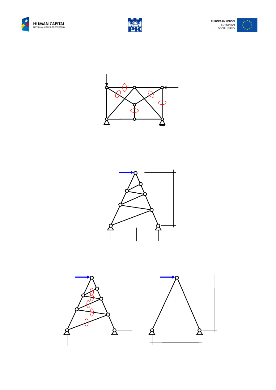
Example of zero force members identification
The numbers in Fig. 11.8 indicate the sequence of nodes where the ZFMT would be applied. The zero
force bars are indicated by “zero” signs.
4
3
2
1
Fig. 11.8 Zero force bars identification
Example of the joint method
The method is suitable for small structures with the limited amount of the members.
2 m
5 m
2 m
400 kN
Fig. 11.9 Simple truss
We start with identifying zero-force members, Fig. 11.10. Beginning from the highest sloping bar to the
lowest, we find that in principle only two lateral bars are “working”.
4 m
2 m
5 m
2 m
400 kN
5 m
Fig. 11.10 Zero force bars and working bars
Adam Paweł Zaborski
Project “The development of the didactic potential of Cracow University of Technology in the range of
modern construction” is co-financed by the European Union within the confines of the European Social Fund
and realized under surveillance of Ministry of Science and Higher Education.
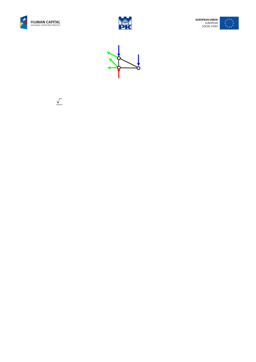
From the top hinge balance, Fig. 11.11:
N
2
N
1
400 kN
Fig. 11.11 Node balance
we get:
2
1
0
N
N
Y
−
=
→
=
∑
5
.
538
,
5
.
538
0
7428
.
0
400
5
2
2
2
400
cos
)
(
400
0
1
2
2
2
2
2
2
1
=
−
=
→
=
+
=
+
+
=
α
+
−
+
→
=
∑
N
N
N
N
N
N
X
kN
Example of section method
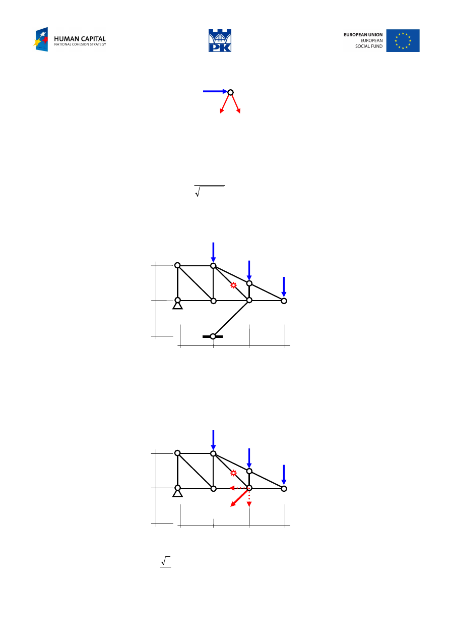
Determine the axial force in the indicated bar, Fig. 11.12.
3 m
3 m
3 m
3 m
3 m
20 kN
40 kN
40 kN
Fig. 11.12 Truss with a bar in question
For the solution we need the force in the lowest sloping bar, not necessarily all constraint reactions. From
the hinge equation for the lower part of the structure we know that the reaction should be along the bar
direction, pointing to the hinge. Moving this free vector to the position of the hinge, we determine the axial
force from the balance condition of the upper part of the structure, Fig. 11.13.
A
3 m
3 m
3 m
3 m
3 m
20 kN
40 kN
40 kN
Fig. 11.13 Axial force in the lower bar
∑
−
=
→
=
⋅
+
⋅
+
⋅
+
⋅
→
=
3
.
127
0
6
2
2
9
20
6
40
3
40
0
N
N
M
A
kN
Adam Paweł Zaborski
Project “The development of the didactic potential of Cracow University of Technology in the range of
modern construction” is co-financed by the European Union within the confines of the European Social Fund
and realized under surveillance of Ministry of Science and Higher Education.
The section, shown in Fig 11.14, gives:
B
N
1
90 kN
3 m
20 kN
40 kN
Fig.11.14 Section method
∑
−
=
→
=
⋅
−
⋅
+
⋅
→
=
71
.
70
0
3
40
3
90
3
2
2
0
1
1
N
N
M
B
kN
Answer: the axial force in the indicated bar is equal to –70.71 kN (compression).
Adam Paweł Zaborski
Project “The development of the didactic potential of Cracow University of Technology in the range of
modern construction” is co-financed by the European Union within the confines of the European Social Fund
and realized under surveillance of Ministry of Science and Higher Education.
Example of Henneberg’s method
Determine the axial force in the indicated bar.
40 kN
70 kN
1
1
1
1
2
1
Fig. 11.15 Structure in question
The structure can be analyzed neither by the joint nor the section methods without a rather large system of
equations. So, we are doomed to the Henneberg’s method.
First, we consider mechanical stability of the structure, Fig. 11.16. From 3ST we find that the structure is
free-body and overall stable.
70
40
R
B
V
A
H
A
3
1
2
Fig. 11.16 Mechanical stability
Reaction calculation gives:
5
.
82
4
3
70
3
40
=
⋅
+
⋅
=
A
V
kN,
5
.
42
4
3
70
1
40
−
=
⋅
−
⋅
=
B
R
kN,
70
=
A
H
kN
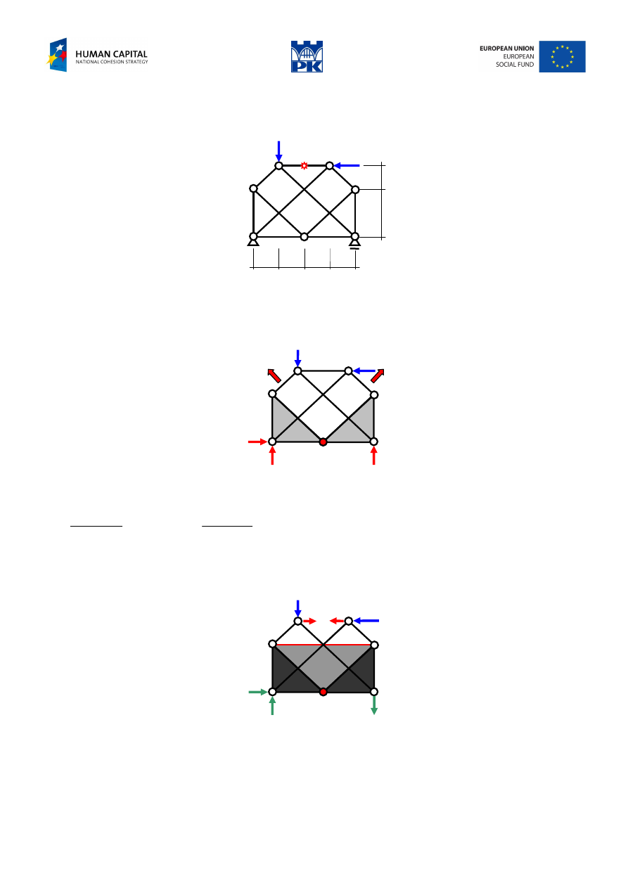
We remove the bar and replace its action by self-equilibrated forces X. To ensure mechanical stability of
the structure we add a substitute bar, assuming its axial force to be zero. An equivalent static scheme with
the analysis of free-body mechanical stability is drawn in Fig. 11.17 where consecutive shields have been
drawn.
42.5
70
82.5
X
X
40
70
Fig. 11.17 Equivalent scheme
We will calculate the axial force in the indicated bar twice: for the so-called basic load (in blue and green
in the Fig. 11.17) and for self-equilibrated forces (in red). Based on the superposition principle, axial force
in the bar due to all loads is a sum of forces in the bar due to basic load and X-times unit self-equilibrated
forces:
)
1
(
)
(
)
(
)
(
N
X
N
N
N
N
P
X
P
⋅
+
=
+
=
.
Adam Paweł Zaborski
Project “The development of the didactic potential of Cracow University of Technology in the range of
modern construction” is co-financed by the European Union within the confines of the European Social Fund
and realized under surveillance of Ministry of Science and Higher Education.
Solution for basic load
40
N
4
N
5
N
3
N
2
70
Fig. 11.18 Solution for basic load
5
.
49
70
2
0
70
2
2
2
2
0
,
0
3
3
3
2
3
2
=
→
=
→
=
−
+
−
→
=
−
=
→
=
∑
∑
N
N
N
N
X
N
N
Y
kN
28
.
28
2
40
0
2
2
2
2
40
0
,
0
5
5
4
5
4
−
=
−
=
→
=
+
+
→
=
=
→
=
∑
∑
N
N
N
Y
N
N
X
kN
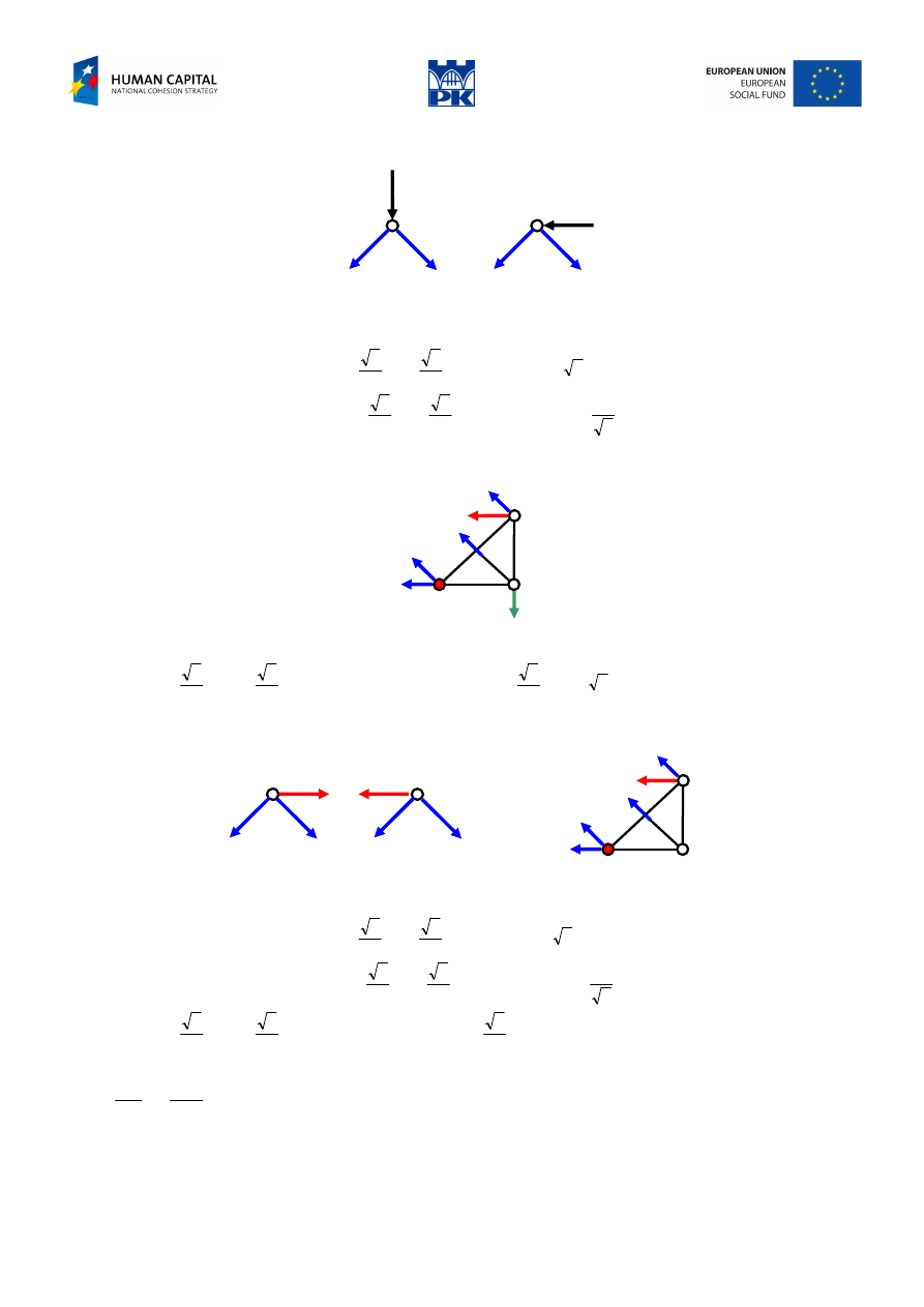
and then, cf. Fig. 11.19, we have:
N
1
B
-28.28
49.5
C
42.5
Fig. 11.19 Solution for basic load – cont.
5
.
7
5
.
42
2
5
.
49
2
2
28
.
28
0
2
4
2
2
2
2
2
0
1
1
3
5
−
=
+
⋅
−
=
→
=
⋅
+
⋅
+
⋅
→
=
∑
B
B
C
N
N
N
N
M
kN
Solution for unit self-equilibrated load
1
1
N
4
N
5
N
3
N
2
N
1
1
-0.7071
0.7071
C
Fig. 11.20 Solution for unit load
7071
.
0
1
2
0
1
2
2
2
2
0
,
3
0
3
3
3
2
2
=
→
=
→
=
−
+
−
→
=
−
=
→
=
∑
∑
N
N
N
N
X
N
N
Y
kN
7071
.
0
2
1
0
2
2
2
2
1
0
,
0
5
5
4
5
4
−
=
−
=
→
=
+
−
→
=
−
=
→
=
∑
∑
N
N
N
X
N
N
Y
kN
5
.
0
7071
.
0
2
2
0
2
4
2
2
2
2
2
0
1
1
1
1
3
5
−
=
⋅
−
=
→
=
⋅
+
⋅
+
⋅
→
=
∑
N
N
N
N
M
C
kN
We have, eventually:
15
5
.
0
5
.
7
1
1
1
1
−
=
−
−
−
=
−
=
N
N
N
B
kN
Adam Paweł Zaborski
Project “The development of the didactic potential of Cracow University of Technology in the range of
modern construction” is co-financed by the European Union within the confines of the European Social Fund
and realized under surveillance of Ministry of Science and Higher Education.
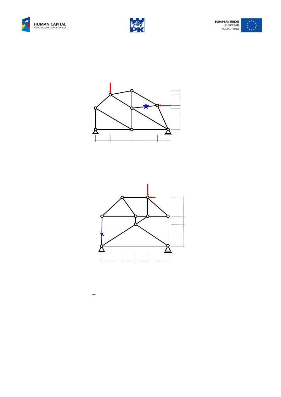
Workshop theme
Determine the forces in the indicated truss member:
a) by the section method (Ritter’s method)
P
2
P
1
0,2
0,1
0,8
1,4
1,0
1,4
1,8
0,6
Fig. 11.21 Truss to be considered by section method
Input data: P
1
= ……. kN, P
2
= ……. kN, dimensions in [m].
b) by the Henneberg’s method
P/2
P
b/2
b
b
a
a/2 a/2
a
Fig. 11.22 Truss to be considered by Henneberg’s method
Input data:
a
= ……. m (1÷4 m)
b
= ……. m (1÷3 m), where:
625
.
0
≠
b
a
P
= ……. kN (50÷250 kN)
Adam Paweł Zaborski
Project “The development of the didactic potential of Cracow University of Technology in the range of
modern construction” is co-financed by the European Union within the confines of the European Social Fund
and realized under surveillance of Ministry of Science and Higher Education.
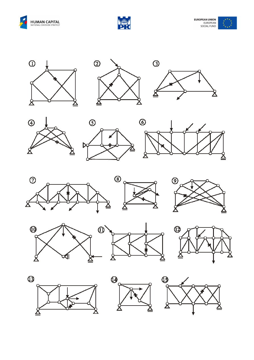
Review problems
Determine the axial force in the indicated element.
Fig 11.21 Review problems

Adam Paweł Zaborski
Project “The development of the didactic potential of Cracow University of Technology in the range of
modern construction” is co-financed by the European Union within the confines of the European Social Fund
and realized under surveillance of Ministry of Science and Higher Education.
Addendum
1
As opposed to a solid block, a truss:
−
uses less material;
−
puts less gravity load on other parts of the structure;
−
leaves space for other things of interest (e.g., cars, cables, wires, people).
You can notice trusses in bridges, radio towers, and large-scale construction equipment. Early airplanes
were flying trusses
2
. Bamboo trusses have been used as scaffoldings for millennia. Birds have had bones
whose internal structure is truss-like since they were dinosaurs.
Trusses are practical sturdy light structures.
Trusses can carry big loads with little use of material and can look nice. They are used in many structures.
Why don’t engineers use trusses for all structural designs? Here are some reasons to consider not using a
truss:
−
trusses are relatively difficult to build, involving many small parts and thus requiring much time and
effort to assemble,
−
trusses can be sensitive to damage when forces are not applied at the anticipated joints; they are
especially sensitive to loads on the middle of the bars,
−
trusses inevitably depend on the tension strength in some bars; some common building materials (e.g.,
concrete, stone, and clay) crack easily when pulled,
−
trusses often have little or no redundancy, so failure in one part can lead to total structural failure,
−
the triangulation that trusses require can use space that is needed for other purposes (e.g., doorways,
rooms),
−
trusses tend to be stiff, and sometimes more flexibility is desirable (e.g., diving boards, car suspensions),
−
in some places some people consider trusses unaesthetic. (e.g., the Washington Monument is not
supposed to look like the Eiffel Tower).
None-the-less, for situations where you want a stiff, light structure that can carry known loads at pre-
defined points, a truss is often a great design choice.
Hints
Tip: Always try to write uncoupled equations set.
Tip: Remember that the bar force is a sliding vector.
Glossary
truss, framework, lattice, latticework – kratownica
truss bar – pręt kratowy
zero force bar – pręt zerowy
hinges balance method, joints method – metoda równoważenia węzłów
Ritter method, sections method – metoda Rittera
Henneberg’s method, bars exchange method – metoda wymiany prętów (Henneberga)
truss post – słupek
cross brace – krzyżulec
top chord – pas górny
bottom chord – pas dolny
truss web configuration – konfiguracja siatki kratownicy
strut – rozpórka, zastrzał
1
excerpt from: Introduction to statics and dynamics, by Andy Ruina and Rudra Pratap, Oxford Univ. Press (Preprint), 2008, p.
249 and 251
2
and, more recently, space vehicles and spacecrafts like Lunar Module and Mars Pathfinder (A.Z.)

Adam Paweł Zaborski
Project “The development of the didactic potential of Cracow University of Technology in the range of
modern construction” is co-financed by the European Union within the confines of the European Social Fund
and realized under surveillance of Ministry of Science and Higher Education.
tie, tie rod, bowstring – ściąg
wind bracing – wiatrownica
sway brace – stężenie poprzeczne
substitute bar – pręt zastępczy
self-equilibrated – samozrównoważony
Wyszukiwarka
Podobne podstrony:
C07 design 11 AZ
C07 design 12 AZ
C07 design 08 AZ
C07 design 02 AZ
C07 design 03 AZ
C07 design 09 az
C07 design 05 AZ
C07 design 10 AZ
C07 design 06 AZ
C07 design 01 AZ
C07 design 03 AZ
C07 design 02 AZ
C07 design 09 AZ
C07 design 10 AZ
C07 design 01 AZ
C07 design 06 AZ
C07 design 08 AZ
C07 design 15 AZ
C07 design 14 AZ
więcej podobnych podstron