Adam Paweł Zaborski
Project “The development of the didactic potential of Cracow University of Technology in the range of
modern construction” is co-financed by the European Union within the confines of the European Social Fund
and realized under surveillance of Ministry of Science and Higher Education.
8. Gerber beams
1
Introduction
hinge-attached beam – a beam made up of simple beams joined flexibly by hinges
We determine the cross-section forces of the hinge-attached beams by dividing them into simple ones.
Note: Each cut across a hinge results in two unknown forces, usually one vertical and one horizontal.
Tip: Serious errors result from lack of unknown forces at a slit hinge.
Gerber beam – a beam made up of simple beams, arranged collinearly and joined one-by-one by hinges
Note: Horizontal translation of the Gerber’s beam should be blocked only once, otherwise the beam is
redundant.
GR: The axial force depends on horizontal component of loading only and can be determined in the first
stage of calculation, just after the calculation of the horizontal reaction.
GR: Horizontal components of loadings are irrelevant to bending moment and shear force calculation and
may be neglected in the further calculation.
Instead of using the hinges’ equations, we rearrange the simple beams in such a way that each beam is
properly supported. In this way we determine the reaction solution order: we start from the highest beams
and finish with the lowest.
Having all simple beams solved separately, we put together the cross-section forces diagrams.
Examples
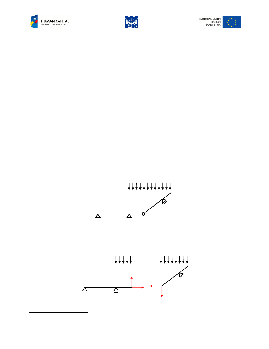
Hinged beam – “nothing new”
Fig. 8.1 Articulated beam
To determine the articulated beams we proceed in the usual way, decomposing the structure into simple
beams. The beams are joined by hinges. Replacing each hinge by the set of internal forces we get the static
schemes ready to use for calculations, Fig. 8.2.
V
H
H
V
Fig. 8.2 Decomposition into simple beams
1
patented in 1886 by Heinrich Gerber
Adam Paweł Zaborski
Project “The development of the didactic potential of Cracow University of Technology in the range of
modern construction” is co-financed by the European Union within the confines of the European Social Fund
and realized under surveillance of Ministry of Science and Higher Education.
Gerber beam
When the axes of the simple beams are collinear and the horizontal translation is taken away only once,
such beam is called the cantilever beam or Gerber beam. The cross-section forces of the beam may be
determined by a simpler method, not using the general way.
Because there is only one horizontal unknown of constraints, we determine its value and make the entire
diagram of axial force, using only horizontal components of the loads.
We “forget” horizontal loads’ components and we consider the vertical components only in the sequel.
Not knowing how to begin with the most important part of loading, we construct an equivalent static
scheme. It consists in ordering the simple beams in a sequence on the basis of the constraints. The highest
beams are calculated first, next the beams of second order and so on.
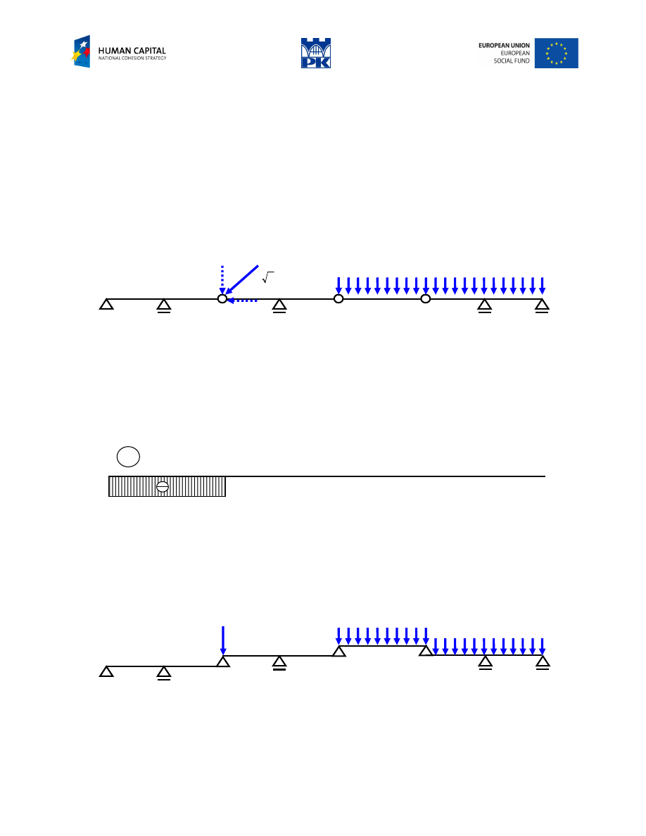
Example
20 kN/m
2
40
2 m
2 m
2 m
2 m
3 m
2 m
2 m
Fig. 8.3 Cantilever (Gerber) beam
Solution:
This is so-called Gerber beam (cantilever beam) because of the axis in the shape of straight line and only
one pin-support, all others being the rollers. We decompose the loads into horizontal and vertical, acting
separately. We determine the horizontal reaction, horizontal cross-section force and construct the diagram
of the axial force, Fig. 8.4.
N
= 0
40
40
Fig. 8.4 Diagram of axial force
In the sequel we neglect all horizontal compounds of the loads, which produce neither bending moments
nor shear forces. Instead of finding vertical reactions from static balance equations, we construct an
equivalent static scheme, placing consecutive beams, determined by the hinges, in position assuring
stability (now the horizontal translation is excluded from our considerations). If the entire beam is stable,
the procedure ends by last beam being stable, too, Fig. 8.5.
20
20
40
Fig. 8.5 Equivalent static scheme
We apply the loads to the upper or lower beam, but only once. The solution can be made starting from the
most upper beams up to the lowest, in turn, Fig. 8.6.

Adam Paweł Zaborski
Project “The development of the didactic potential of Cracow University of Technology in the range of
modern construction” is co-financed by the European Union within the confines of the European Social Fund
and realized under surveillance of Ministry of Science and Higher Education.
30
30
+
30
30
22.5
60
30
30
30
60
30
30
70
70
100
30
140
30
30
30
40
10
10
10
20
10
Fig. 8.6 Simple beams sequence
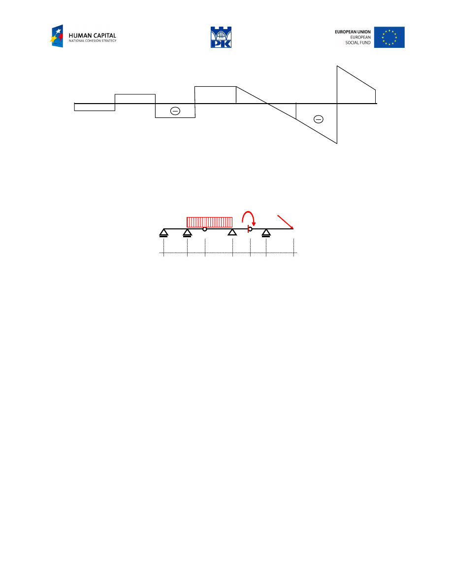
Collective diagrams:
M
100
22.5
60
20
Fig. 8.7 Bending moments
Adam Paweł Zaborski
Project “The development of the didactic potential of Cracow University of Technology in the range of
modern construction” is co-financed by the European Union within the confines of the European Social Fund
and realized under surveillance of Ministry of Science and Higher Education.
30
10
10
30
70
30
70
30
30
10
10
Fig. 8.8 Shear forces of the cantilever beam
Workshop theme
Construct the diagrams of the cross-section forces through the equivalent scheme and the simple beams.
P
M
1
q
a
c
b
b
a
a
Fig. 8.9 Cantilever beam
Input data:
a
= ……. m (2÷3 m)
b
= ……. m (1.5÷2.5 m)
c
= ……. m (1÷2 m)
P
= ……. kN (20÷50 kN)
M
1
= ……. kNm (10÷40 kNm)
q
= ……. kN/m (15÷55 kN/m)
Adam Paweł Zaborski
Project “The development of the didactic potential of Cracow University of Technology in the range of
modern construction” is co-financed by the European Union within the confines of the European Social Fund
and realized under surveillance of Ministry of Science and Higher Education.
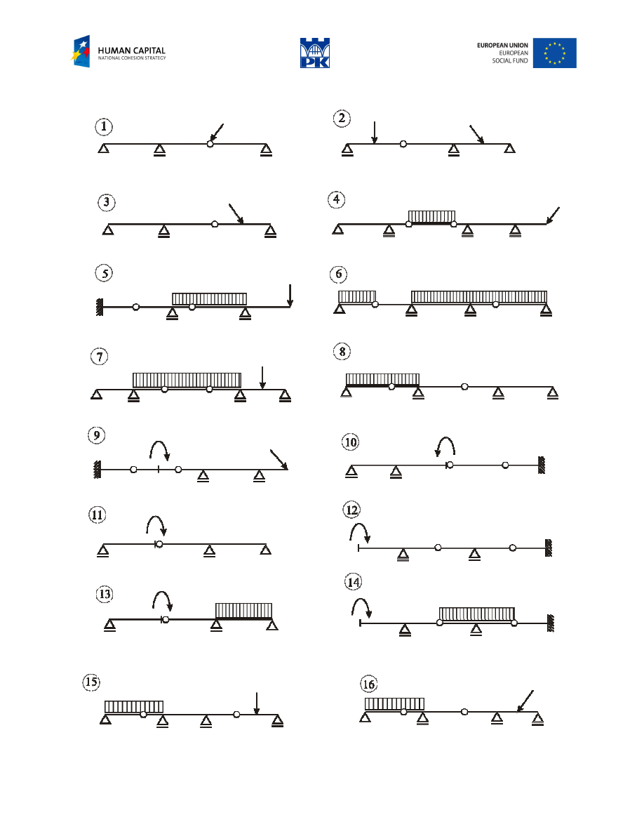
Review problems
Fig. 8.10 Review problems

Adam Paweł Zaborski
Project “The development of the didactic potential of Cracow University of Technology in the range of
modern construction” is co-financed by the European Union within the confines of the European Social Fund
and realized under surveillance of Ministry of Science and Higher Education.
Addendum
Tip: Keep in mind that the hinge is not the characteristic point (for functions of cross-section forces).
Simply, the bending moment zeroes at a hinge. Nothing more, but it is pretty much.
2
The Gerber beam idea consists of introducing hinges in a continuous beam to make it isostatic, so that it
becomes a series of simply supported beams extended at their ends by cantilevers in alternate spans that are
linked to each other by beams supported on the cantilever ends. This system gives the advantages of the
continuous beam and of the isostatic structure:
− the continuous beam because the bending moment distribution alternate positively and negatively at
supports and span centres, the same as in the beam and, therefore, its maximum values are less than in
the supported beam;
− the isostatic structure, because its stresses are not affected by deformations of the ground where they are
resisted, which is a fundamental and sometimes determining condition when the foundation ground is
not good.
The Gerber beam has other advantages over the continuous type:
− the main supports can be fixed and hinges made movable, with deformation being accumulated in them
due to the structure’s temperature
− determining its member force distribution analytically is much easier than in the continuous beam
precisely due to its isostatism.
Glossary
hinge-attached beam – belka przegubowa
continuous beam – belka ciągła (na wielu podporach)
Gerber beam, cantilever beam – belka przegubowa, belka gerberowska
isostatic – statycznie wyznaczalny
isostatism – statyczna wyznaczalność
statically indeterminate; redundant – statycznie niewyznaczalny
2
excerpt from: Bridge engineering: a global perspective, by Leonardo Fernandez Troyano, Thomas Telford ed., p. 354
Wyszukiwarka
Podobne podstrony:
C07 design 08 AZ
C07 design 11 AZ
C07 design 12 AZ
C07 design 02 AZ
C07 design 03 AZ
C07 design 09 az
C07 design 05 AZ
C07 design 10 AZ
C07 design 06 AZ
C07 design 01 AZ
C07 design 03 AZ
C07 design 02 AZ
C07 design 09 AZ
C07 design 10 AZ
C07 design 01 AZ
C07 design 06 AZ
C07 design 15 AZ
C07 design 14 AZ
C07 design 13 AZ
więcej podobnych podstron