Adam Paweł Zaborski
Project “The development of the didactic potential of Cracow University of Technology in the range of
modern construction” is co-financed by the European Union within the confines of the European Social Fund
and realized under surveillance of Ministry of Science and Higher Education.
10. Arches
Introduction
Definitions
arc – a curved line
arch – a curved structure that supports the weight of something above it
rational axis – an arch axis with the bending moment and shear force equal to zero for given loading
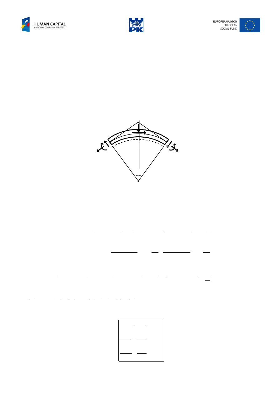
Differential relationships of the cross-section forces
ρ
∆ϕ
A
N(s)
M(s)
Q(s)
q(s+
β∆
s)
∆
s
p(s+γ
∆
s)
∆
s
Q(s+
∆
s)
M(s+
∆
s)
N(s+
∆
s)
Fig. 10.1 Balance of an arch element
Let’s consider balance of bar element ds with plane curved axis, loaded by continuous loading q –
perpendicular to the axis and p – tangent to the axis. The loading as well as cross-section forces are drawn
following the sign convention. The loadings can be replaced by the resultants, which are drawn in Fig.
10.1, according to Lagrange’s theorem and neglecting small quantities of higher order. The cut out element
should be in equilibrium, so, we have the following for the cast on the vertical axis:
,
0
2
sin
)
(
)
(
2
2
cos
)
(
)
(
=
∆
∆
∆
+
+
−
∆
∆
∆
+
−
∆
∆
+
−
ϕ
α
ϕ
α
β
s
ds
s
s
dN
s
N
s
ds
s
s
dQ
s
s
s
q
N
Q
for the cast on the horizontal axis:
,
0
2
cos
)
(
2
sin
)
(
)
(
2
)
(
=
∆
∆
∆
+
+
∆
∆
∆
+
+
−
∆
∆
+
ϕ
α
ϕ
α
γ
s
ds
s
s
dN
s
ds
s
s
dQ
s
Q
s
s
s
p
N
Q
and for the moments about the point A:
0
cos
)
(
2
tan
)
(
)
(
2
)
(
2
=
−
∆
∆
+
−
∆
∆
∆
+
+
+
∆
∆
+
−
∆
ρ
ρ
γ
ϕ
ρ
α
α
ϕ
s
s
s
p
s
ds
s
s
dQ
s
Q
s
ds
s
s
dM
Q
M
Dividing the equations by
∆
s, for small angle
∆ϕ
:
,
2
2
,
2
2
tan
,
2
2
sin
,
1
2
cos
ρ
∆
→
ϕ
∆
ϕ
∆
→
ϕ
∆
ϕ
∆
→
ϕ
∆
→
ϕ
∆
s
we have,
)
(
)
(
0
s
f
s
s
f
s
→
∆
α
+
⇒
→
∆
for
, and finally we get the differential relationships between the loadings
and cross-section forces in the form:
)
(
)
(
)
(
)
(
)
(
)
(
)
(
)
(
s
p
s
Q
ds
s
dN
s
q
s
N
ds
s
dQ
s
Q
ds
s
dM
−
=
−
−
=
+
=
ρ
ρ
Adam Paweł Zaborski
Project “The development of the didactic potential of Cracow University of Technology in the range of
modern construction” is co-financed by the European Union within the confines of the European Social Fund
and realized under surveillance of Ministry of Science and Higher Education.
The signs in the equations above depend on the sign convention.
Tip: From the first equation we see that the derivative of the bending moment with respect to curvilinear
coordinate is equal to the shear force (exact to its sign depending on assumed undersides).
Tip: The zeroing of the shear force at a cross-section means the bending moment’s extremum at the cross-
section.
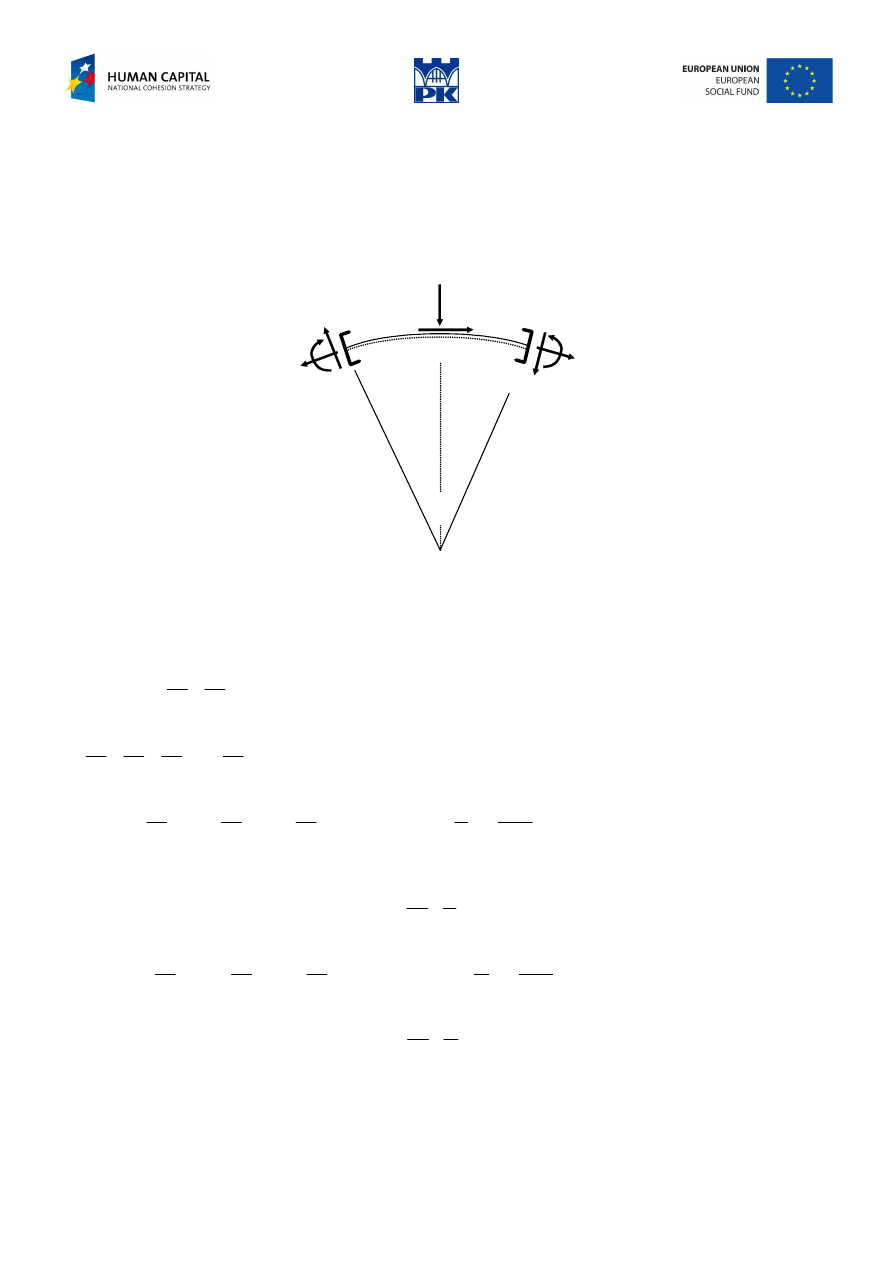
(different variant of the proof)
ρ
pds
qds
ds
N+dN
M+dM
Q+dQ
N
M
Q
d
ϕ
Fig. 10.2 Infinitesimal element of arch
The curved bar in Fig. 10.2 is loaded by tangent loading p and perpendicular loading q. An infinitesimal
element ds, cut out from the arch, is loaded by cross-section forces resulting from the equivalence theorem.
We can assume, exactly to the small quantities of higher order, that the element has constant curvature
radius
ρ
and that the loading can be replaced by its resultants, as shown in Fig. 10.2. Moreover:
ρ
ϕ
ϕ
ρ
2
2
ds
d
d
ds
=
⇒
=
,
and because the angle d
ϕ
is also infinitesimal:
1
2
cos
,
2
2
2
sin
≈
=
≈
ϕ
ρ
ϕ
ϕ
d
ds
d
d
.
Casting on the x axis, we get:
0
2
0
2
sin
2
sin
2
2
cos
=
−
−
+
⇒
=
−
−
+
ρ
ρ
ϕ
ϕ
ϕ
dQds
ds
Q
dN
pds
d
dQ
d
Q
d
dN
pds
.
The last term before the equal sign is small quantity of higher order that can be neglected. Dividing by ds,
we have:
p
Q
ds
dN
−
=
−
ρ
.
Casting on y axis, we have:
0
2
0
2
sin
2
sin
2
2
cos
=
−
−
−
−
⇒
=
−
−
−
−
ρ
ρ
ϕ
ϕ
ϕ
dNds
ds
N
dQ
qds
d
dN
d
N
d
dQ
qds
.
Similarly, we finally get:
q
N
ds
dQ
−
=
+
ρ
.
In the calculation of moment about the point of the resultant intersection, we take into account only the
point moments at the ends and vertical components of shear forces , neglecting straight away other
components as the small quantities of higher order:
Adam Paweł Zaborski
Project “The development of the didactic potential of Cracow University of Technology in the range of
modern construction” is co-financed by the European Union within the confines of the European Social Fund
and realized under surveillance of Ministry of Science and Higher Education.
0
2
0
2
cos
2
2
2
=
+
+
−
⇒
=
+
+
−
ds
dQ
Qds
dM
d
ds
dQ
ds
Q
dM
ϕ
.
Neglecting small quantity of higher order again and dividing by ds, we get:
Q
ds
dM
=
.
Examples
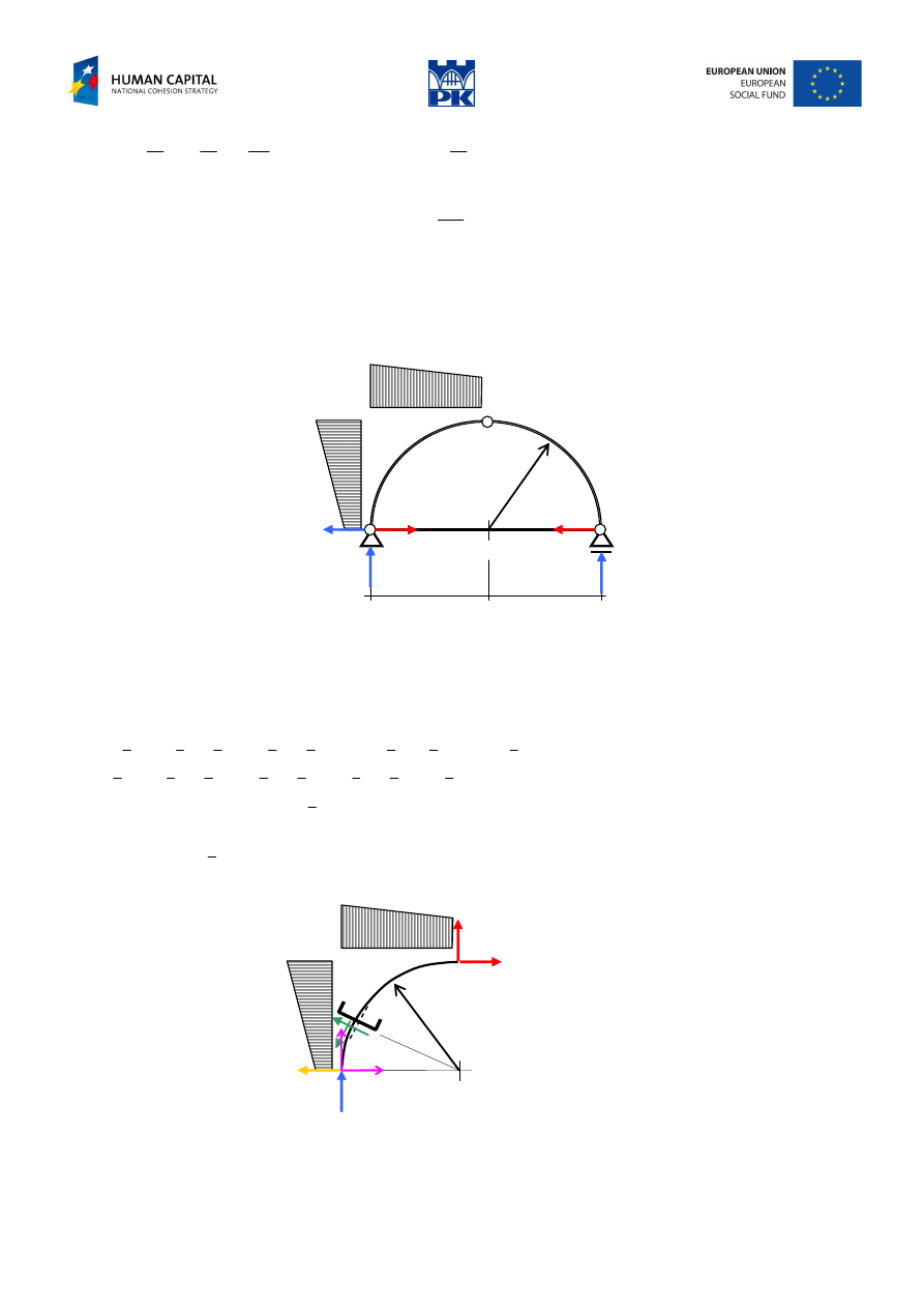
Circular arch
Draw the cross-section forces diagrams of the arch in Fig. 10.3.
R
R
R
B
V
A
H
A
2 m
2 m
10
30
30
20
Fig. 10.3 Circular arch with bowstring
Solution
Calculation of reactions:
40
=
A
H
kN
(
)
(
)
67
.
26
2
2
2
20
2
2
2
30
2
2
30
2
2
10
4
3
1
2
1
3
2
2
1
3
2
2
1
3
1
2
1
=
→
⋅
+
⋅
⋅
⋅
+
⋅
+
⋅
⋅
⋅
+
⋅
⋅
⋅
⋅
−
⋅
⋅
⋅
⋅
−
=
A
A
V
V
kN
33
.
23
2
2
20
2
2
30
2
2
30
2
2
10
4
3
2
2
1
3
1
2
1
3
2
2
1
3
1
2
1
=
→
⋅
⋅
⋅
⋅
+
⋅
⋅
⋅
⋅
+
⋅
⋅
⋅
⋅
+
⋅
⋅
⋅
⋅
=
B
B
R
R
kN
Verification:
0
2
)
20
30
(
67
.
26
33
.
23
2
1
=
⋅
+
⋅
−
+
=
∑
Y
, OK
Force at the bowstring:
∑
=
⋅
=
→
=
33
.
23
2
0
2
1
B
R
C
R
R
M
kN
1
st
interval:
y
x
r
α
V
H
26.67
16.67
10
30
30
20
α
=
α
−
=
sin
)
cos
1
(
R
y
R
x
Fig. 10.4 1
st
interval
Adam Paweł Zaborski
Project “The development of the didactic potential of Cracow University of Technology in the range of
modern construction” is co-financed by the European Union within the confines of the European Social Fund
and realized under surveillance of Ministry of Science and Higher Education.
6
2
10
2
30
6
2
20
2
10
67
.
16
67
.
26
)
(
3
2
3
2
x
x
y
y
y
x
M
⋅
+
−
⋅
−
−
⋅
+
⋅
=
α
α
−
−
+
α
+
−
=
α
cos
2
10
10
67
.
16
sin
2
5
30
67
.
26
)
(
2
2
y
y
x
x
Q
α
−
−
+
α
−
+
−
=
α
sin
2
10
10
67
.
16
cos
2
5
30
67
.
26
)
(
2
2
y
y
x
x
N
2
nd
interval
23.33
23.33
α
=
α
−
=
sin
)
cos
1
(
R
y
R
x
y
x
r
α
Fig. 10.5 2
nd
interval
y
x
M
33
.
23
33
.
23
)
(
−
=
α
α
−
α
=
α
sin
33
.
23
cos
33
.
23
)
(
Q
α
−
α
−
=
α
cos
33
.
23
sin
33
.
23
)
(
N
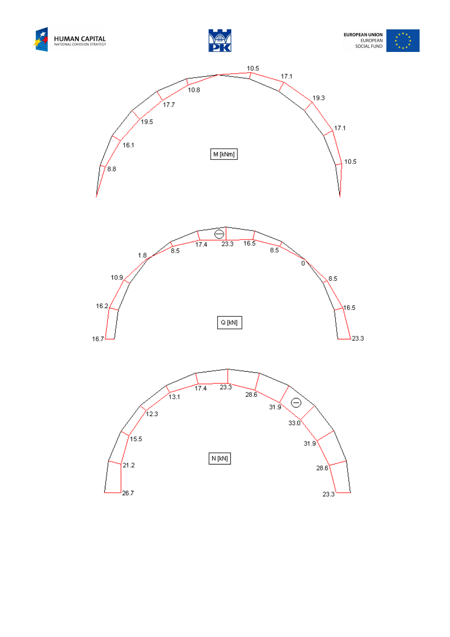
Numerical results are presented in Tab. 10.1:
alpha
x
y
M
Q
N
0
0
0
0
16,67
-26,67
0,26
0,07
0,52
8,81
16,18
-21,17
0,52
0,27
1,00
16,09
10,85
-15,46
0,79
0,59
1,41
19,50
1,76
-12,32
1,05
1,00
1,73
17,72
-8,54
-13,14
1,31
1,48
1,93
10,82
-17,40
-17,40
1,57
2,00
2,00
0,01
-23,33
-23,33
alpha
x
1
y
1
M
Q
N
1,57
2,00
2,00
-0,00
-23,33
-23,33
1,31
1,48
1,93
-10,49
-16,50
-28,57
1,05
1,00
1,73
-17,08
-8,54
-31,87
0,79
0,59
1,41
-19,33
0,00
-32,99
0,52
0,27
1,00
-17,08
8,54
-31,87
0,26
0,07
0,52
-10,49
16,50
-28,57
0
0
0
0
23,33
-23,33
Tab. 10.1 Circular arch – numerical results
The diagrams of the cross-section forces are shown in Fig. 10.6, 10.7 and 10.8.
Adam Paweł Zaborski
Project “The development of the didactic potential of Cracow University of Technology in the range of
modern construction” is co-financed by the European Union within the confines of the European Social Fund
and realized under surveillance of Ministry of Science and Higher Education.
Fig. 10.6 Circular arch – bending moments
Fig. 10.7 Circular arch – shearing forces
Fig. 10.8 Circular arch – axial forces
Adam Paweł Zaborski
Project “The development of the didactic potential of Cracow University of Technology in the range of
modern construction” is co-financed by the European Union within the confines of the European Social Fund
and realized under surveillance of Ministry of Science and Higher Education.
Non-circular arch
α
α
y
x
15 kN
R
B
H
A
V
A
30 kN/m
10 kN/m
2 m
3 m
3 m
Fig. 10.9 Parabolic arch
Solution
Constraints reactions:
15
=
A
H
kN
5
.
12
1
3
20
5
.
1
3
10
6
3
1
=
→
⋅
⋅
⋅
+
⋅
⋅
=
A
A
V
V
kN
5
.
47
5
3
20
5
.
4
3
10
6
2
1
=
→
⋅
⋅
⋅
+
⋅
⋅
=
B
B
R
R
kN
Verification:
0
60
5
.
47
5
.
12
=
−
+
=
∑
Y
, OK
Equation of the arch axis:
c
bx
ax
x
y
+
+
=
2
)
(
, with the conditions:
0
)
6
(
,
2
)
3
(
,
0
)
0
(
=
=
=
y
y
y
, which gives:
x
x
x
y
3
4
9
2
)
(
2
+
−
=
, and
α
=
+
−
=
tan
3
4
9
4
)
(
'
x
x
y
1
st
interval
y
H
x
V
x
M
A
A
−
=
)
(
α
−
α
=
sin
cos
)
(
A
A
H
V
x
Q
α
−
α
−
=
cos
sin
)
(
A
A
H
V
x
N
2
nd
interval
6
)
3
(
3
20
2
)
3
(
10
)
(
3
2
−
⋅
−
−
−
−
=
x
x
y
H
x
V
x
M
A
A
α
−
α
−
−
−
−
=
sin
cos
2
)
3
(
3
20
)
3
(
10
)
(
2
A
A
H
x
x
V
x
Q
α
−
α
−
+
−
+
−
=
cos
sin
2
)
3
(
3
20
)
3
(
10
)
(
2
A
A
H
x
x
V
x
N
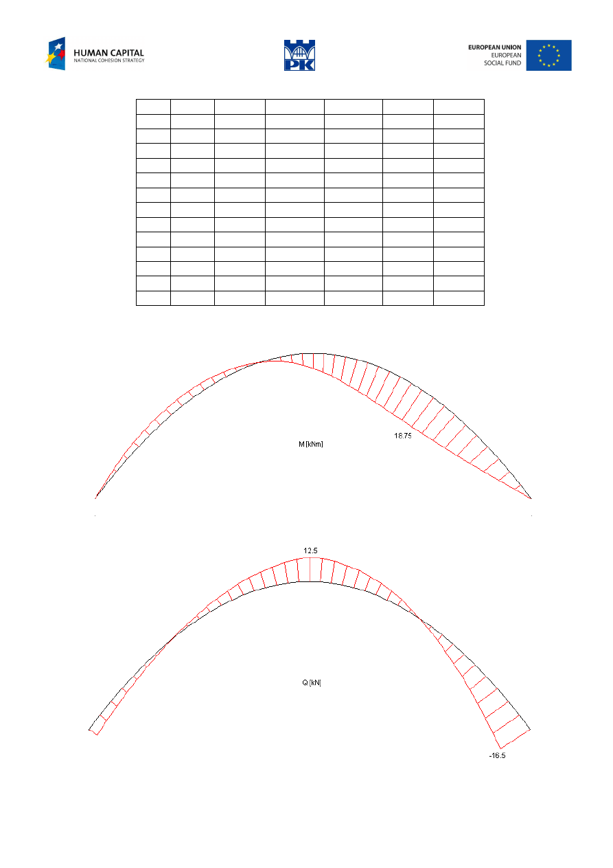
The numerical results obtained by Matlab are shown in the Tab. 10.2 and the diagrams of the cross-section
forces in the Fig. 10.10, 10.11 and 10.12.
Adam Paweł Zaborski
Project “The development of the didactic potential of Cracow University of Technology in the range of
modern construction” is co-financed by the European Union within the confines of the European Social Fund
and realized under surveillance of Ministry of Science and Higher Education.
x
y
cosine
sine
M
Q
N
0
0
0.6000
0.8000
0
-4.50
-19.00
0.5
0.61
0.6690
0.7433
-2.92
-2.79
-19.33
1.0
1.11
0.7474
0.6644
-4.17
-0.62
-19.52
1.5
1.50
0.8321
0.5547
-3.75
2.08
-19.41
2.0
1.78
0.9138
0.4061
-1.67
5.33
-18.78
2.5
1.94
0.9762
0.2169
2.08
8.95
-17.35
3.0
2.00
1.0000
0
7.5
12.50
-15.00
3.5
1.94
0.9762
-0.2169
13.19
9.76
-13.20
4.0
1.78
0.9138
-0.4061
17.22
5.33
-14.05
4.5
1.50
0.8321
-0.5547
18.75
0
-18.03
5.0
1.11
0.7474
-0.6644
16.94
-5.61
-25.05
5.5
0.61
0.6690
-0.7433
10.97
-11.15
-34.81
6.0
0
0.6000
-0.8000
0
-16.5
-47.00
Tab. 10.2 Parabolic arch – numerical results
Fig. 10.10 Parabolic arch – bending moments
Fig. 10.11 Parabolic arch – shear forces
Adam Paweł Zaborski
Project “The development of the didactic potential of Cracow University of Technology in the range of
modern construction” is co-financed by the European Union within the confines of the European Social Fund
and realized under surveillance of Ministry of Science and Higher Education.
Fig. 10.12 Parabolic arch – axial forces
Workshop theme
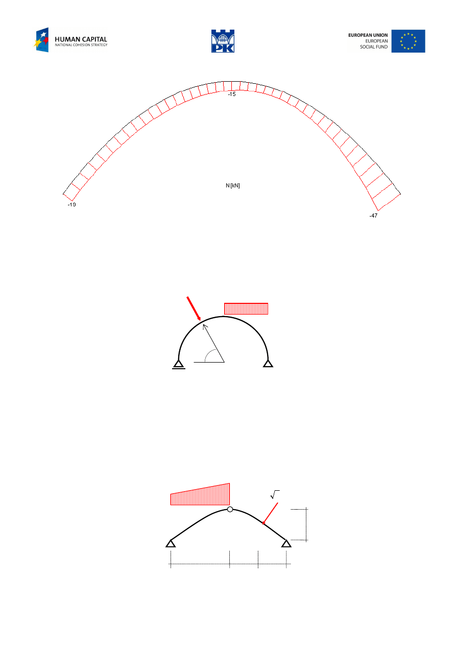
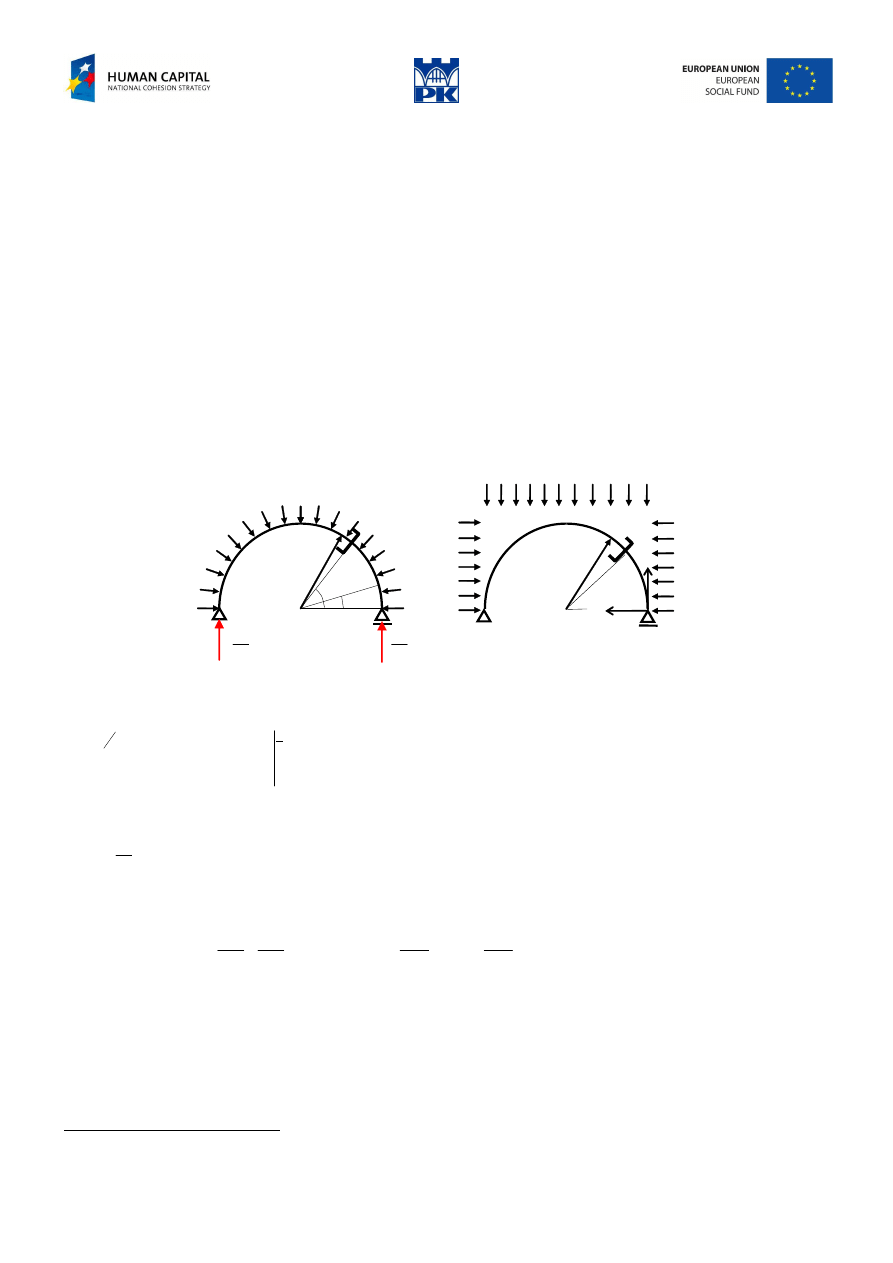
Draw the diagrams of the cross-section forces of the circular and parabolic arches in Fig. 10.13 and 10.14.
a) circular arch
q
P
R
60
°
Fig. 10.13 Circular arch
Input data:
R = ……. m (1.5
÷
4 m)
P = ……. kN (10
÷
50 kN)
q = ……. kN/m (10
÷
40 kN/m)
b) parabolic arch
q
2q
f
0.5l
0.25l 0.25l
P
2
Fig. 10.14 Parabolic arch
Adam Paweł Zaborski
Project “The development of the didactic potential of Cracow University of Technology in the range of
modern construction” is co-financed by the European Union within the confines of the European Social Fund
and realized under surveillance of Ministry of Science and Higher Education.
Input data:
l = ……. m (2
÷
8 m)
f = ……. m (0.4
÷
1.2 l)
P = ……. kN (10
÷
50 kN)
q = ……. kN/m (5
÷
40 kN/m)
Review problems
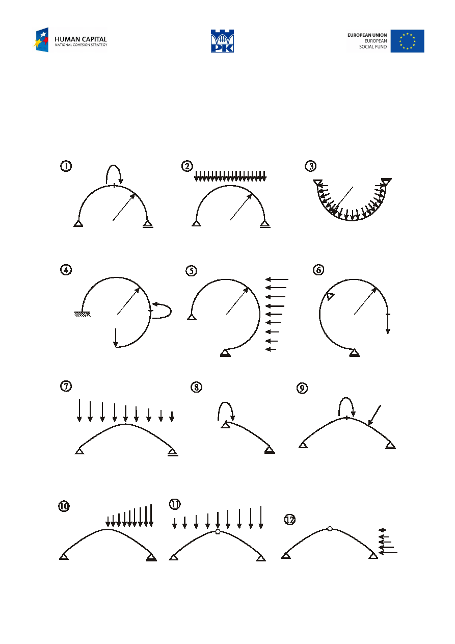
Write down the cross-section forces of the structures in Fig. 10.15 at any given cross-section.
Fig. 10.15 Arches – review problems
Adam Paweł Zaborski
Project “The development of the didactic potential of Cracow University of Technology in the range of
modern construction” is co-financed by the European Union within the confines of the European Social Fund
and realized under surveillance of Ministry of Science and Higher Education.
Addendum
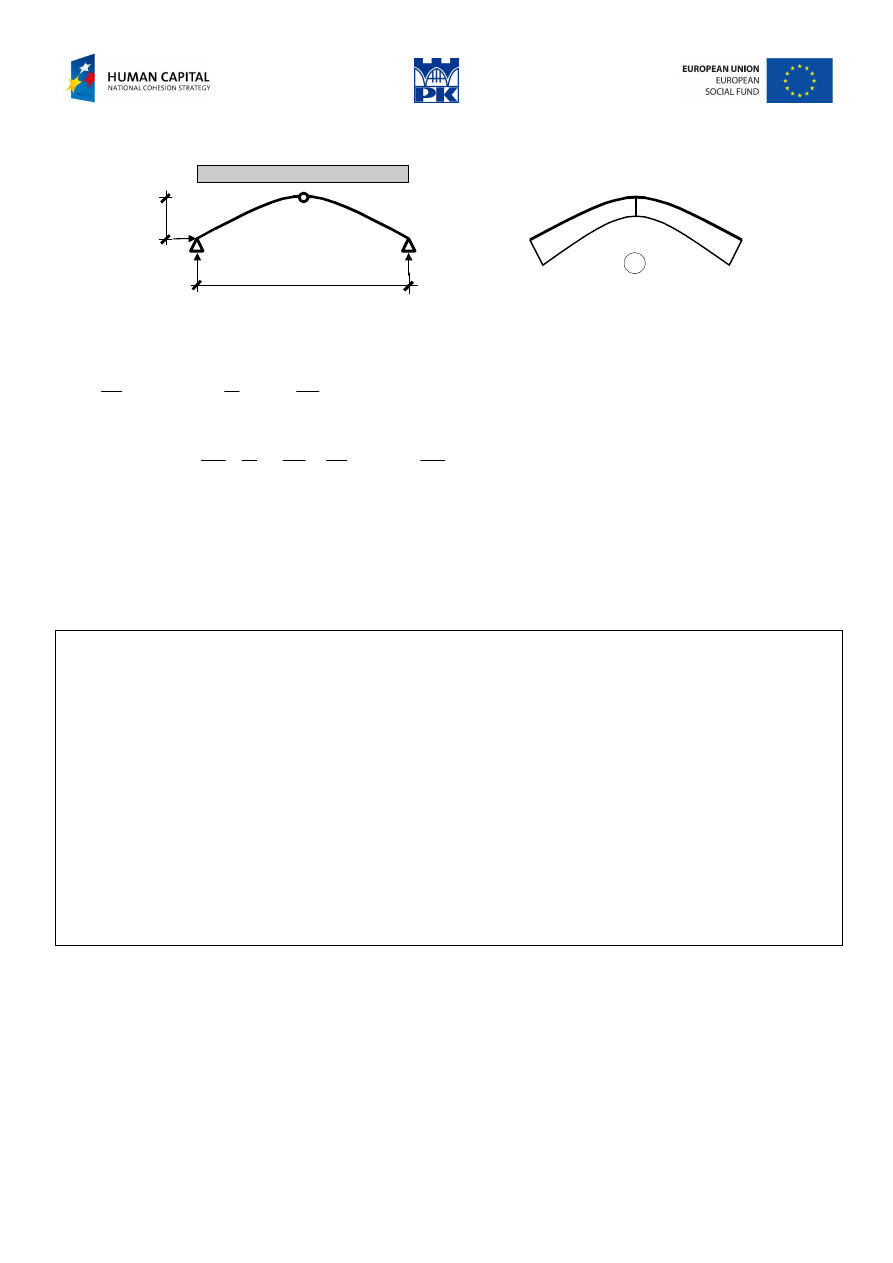
The arch with neither bowstring nor horizontal constraint is a curved beam, not an arch.
1
The main qualities of the arch are a result of its resistant behavior:
−
the absence of tension enables arches to be built with material that do not resist tension, as the case of
structures built with juxtaposed elements; the arch is, therefore, the only valid structure for crossing
spans or covering spaces of a certain size in some architecture because this material’s technology
requires it to be broken down into small-sized elements, which are juxtaposed and, therefore, the overall
is unable to resist tension;
−
the arch aspires to work in the ideal manner, which is through axial forces only, avoiding bending
forces, allowing the amount of material the structure requires to be reduced to a minimum.
−
the three-hinged arch is isostatic, so the cross-section forces are not affected by support deformations
nor phenomena of creep, shrinkage or temperature.
Examples of rational arch axis
Example 1
Circular arch under radial loading.
q
α
x
y
q
q
2
W
2
W
q
R
β
α
Fig. 10.16 Circular arches with equivalent loadings
Vertical resultant reaction:
(
)
qR
qR
qR
qR
W
2
)
1
0
(
2
cos
2
sin
2
2
0
2
0
=
−
=
α
−
=
α
α
=
π
∫
π
d
Cross-section force at
α
cross-section:
bending moment:
(
)
(
)
[
]
0
)
1
(cos
cos
sin
sin
)
cos
1
(
cos
cos
sin
sin
sin
cos
)
cos
1
(
2
)
(
2
2
2
0
=
=
−
α
α
−
α
α
−
α
−
=
=
α
−
β
β
+
β
−
α
β
β
−
α
−
=
∫
α
K
K
K
qR
qR
qR
R
qR
R
W
a
M
d
The same (using a different method):
0
cos
)
cos
1
(
)
cos
1
(
2
sin
2
)
cos
1
(
2
2
)
cos
1
(
)
(
2
2
2
2
2
2
2
2
2
2
2
=
=
α
+
−
α
−
=
=
α
−
−
α
−
α
−
=
−
−
α
−
=
α
K
K
K
qR
qR
qR
qR
qR
qR
qx
qy
qR
M
shear force:
0
cos
sin
)
cos
1
(
sin
sin
cos
sin
sin
)
(
=
=
α
α
+
α
−
α
+
α
−
=
α
+
α
+
α
−
=
α
K
qR
qR
qR
qy
qx
qR
Q
axial force:
const
=
−
=
=
α
−
α
α
−
+
α
−
=
α
−
α
+
α
−
=
qR
qR
qR
qR
qy
qx
qR
x
N
K
2
sin
cos
)
cos
1
(
cos
sin
cos
cos
)
(
1
excerpt from: Bridge engineering: a global perspective, b y Leonardo Fernandez Troyano, ed. Thomas Telford, p. 269-270
Adam Paweł Zaborski
Project “The development of the didactic potential of Cracow University of Technology in the range of
modern construction” is co-financed by the European Union within the confines of the European Social Fund
and realized under surveillance of Ministry of Science and Higher Education.
Example 2
H
A
N
R
A
H
A
f
q
l
Fig. 10.17 Parabolic 3-hinges arch under constant continuous loading
We find the equation of arch axis in the form of 2
nd
order parabola with height f and span l and calculate
reactions for this 3-hinges system:
(
)
f
ql
H
ql
R
lx
x
l
f
y
A
A
8
,
2
,
4
2
2
2
=
=
−
−
=
.
The bending moment equation reads:
(
)
0
2
4
8
2
2
)
(
2
2
2
2
2
=
=
−
−
−
−
=
−
−
=
K
qx
lx
x
l
f
f
ql
x
ql
qx
y
H
x
R
x
M
A
A
.
From the bending moment identically equal to zero we see that the shear force is identically equal to zero
and the arch works in compression only. So the arch axis is rational.
Matlab code for drawing cross-section forces of the arches
To draw the cross-section forces for the arches we need the points at the arch’s axis and the values of the
cross-section forces, scaled with a suitable parameter. The values of the forces should be drawn
perpendicular to the curved axis. The program code which realizes the problem is given in the table 10.3.
n = 20; % some number of points
figure(1) % first separate figure of bending moments
plot(x,y, 'k'), axis equal, hold on % x, y – axis points (in black color)
x1(n) = 0; y1(n) = 0; k_m = 0.01; % memory allocation and scale coefficient
for i = 1: n % bending moment will be drawn downwards (for other forces put opposite sign)
% alf(i) – angle between tangent and axis
x1(i) = x(i) + k_m * M(i) * cos(alf(i));
y1(i) = y(i) - k_m * M(i) * sin(alf(i));
end
plot(x1,y1,'r'), hold on % diagram points (in red color)
for i = 1: n % loop for diagram hatching
line([x(i) x1(i)], [y(i) y1(i)], 'Color', [1 0 0]) % the color is red here
end
hold off
(repeat as figure(2) and figure(3) for shear and axial forces)
Tab. 10.3 Matlab code for drawing the circular arch
Glossary
arc – łuk (kształt linii albo broń miotająca strzały)
arch – łuk (sklepienie łukowe)
rational axis – oś racjonalna
bowstring, tie – ściąg
springing – wezgłowie, wsparcie, kliniec
keystone – klucz, zwornik
Wyszukiwarka
Podobne podstrony:
C07 design 10 AZ
C07 design 11 AZ
C07 design 12 AZ
C07 design 08 AZ
C07 design 02 AZ
C07 design 03 AZ
C07 design 09 az
C07 design 05 AZ
C07 design 06 AZ
C07 design 01 AZ
C07 design 03 AZ
C07 design 02 AZ
C07 design 09 AZ
C07 design 01 AZ
C07 design 06 AZ
C07 design 08 AZ
C07 design 15 AZ
C07 design 14 AZ
C07 design 13 AZ
więcej podobnych podstron