Adam Paweł Zaborski
Project “The development of the didactic potential of Cracow University of Technology in the range of
modern construction” is co-financed by the European Union within the confines of the European Social Fund
and realized under surveillance of Ministry of Science and Higher Education.
12. Combined structures
Introduction
Definitions
combined structure – a structure with parts of different kinds: frame, arch, truss
truss bar – a bar with constant axial force only
beam (frame) bar – a bar with full set of cross-section forces (usu. not constant)
Solution
The first very important step consists of the geometric stability analysis and truss/beam bars recognition.
The importance of the geometric rigidity analysis is obvious: it predicts reaction calculation. If the structure
is free-body rigid, reaction calculation should be easy and “standard” (the use of equilibrium equations
only). If not, some additional effort should be made (at least the hinge’s equation).
Next step consists in the distinction between beam and truss bars. The truss members’ forces are
determined first. Having the beam bars forces also determined, we construct the cross-section forces
diagrams as a final result. Additional verifications complete the work.
Example
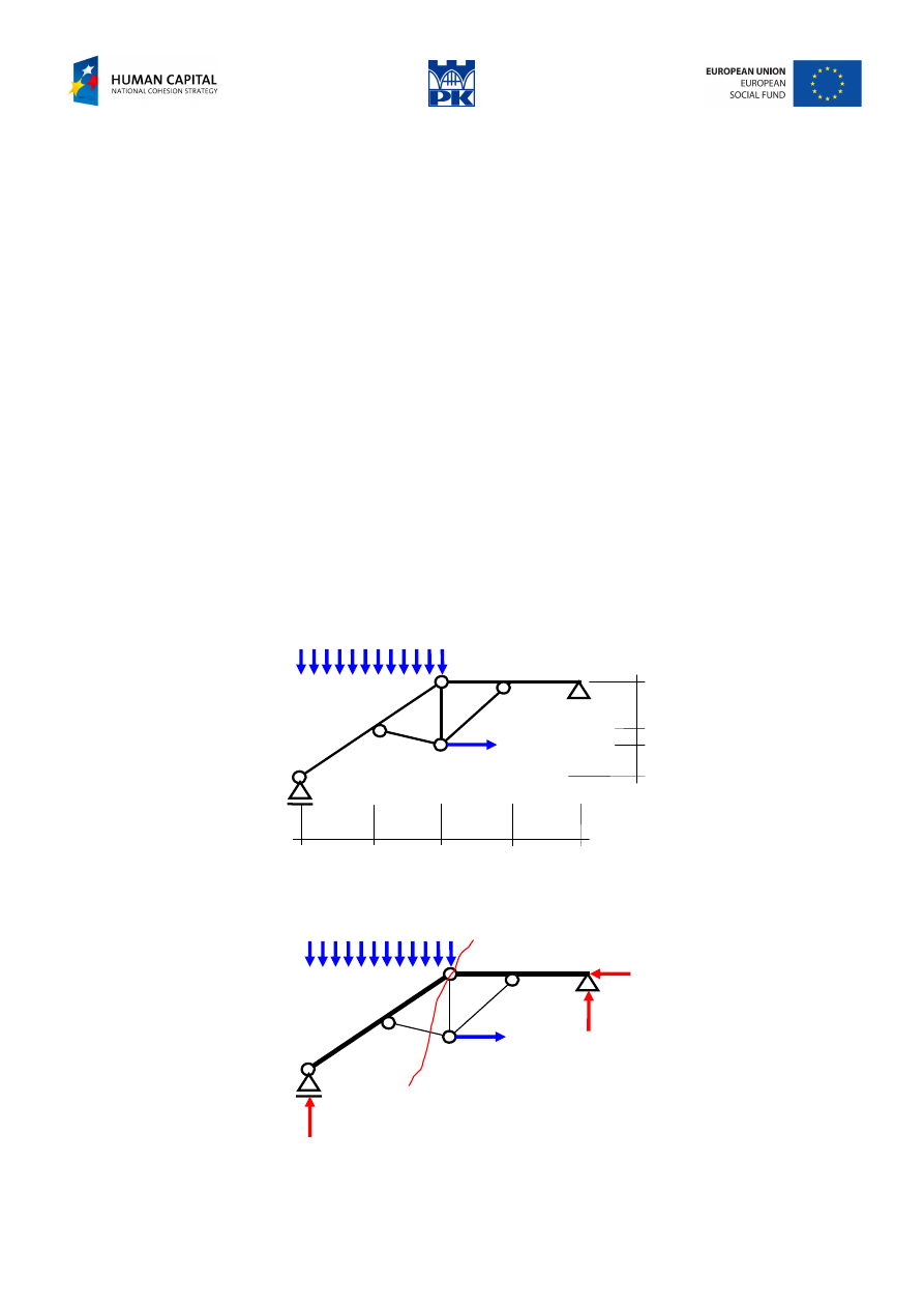
Free-body stable structure
10 kN
35 kN
0.5
1.5
1
2
2
2
2
Fig. 12.1 Free-body stable structure
We distinguish the beam elements by making them thicker, Fig. 12.2.
α
α
115
40
25
40 kN
35 kN
Fig. 12.2 Beam and truss elements and section
Adam Paweł Zaborski
Project “The development of the didactic potential of Cracow University of Technology in the range of
modern construction” is co-financed by the European Union within the confines of the European Social Fund
and realized under surveillance of Ministry of Science and Higher Education.
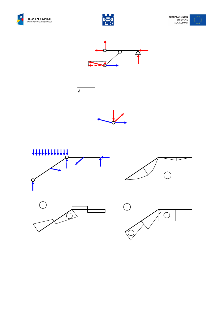
To calculate the truss bar forces we cut the structure through the hinge and one truss bar, Fig. 12.3.
N
1
C
α
α
40
25
40 kN
Fig. 12.3 Right part of the structure
∑
=
→
=
+
⋅
⋅
+
⋅
−
⋅
−
→
=
77
.
92
0
5
.
0
2
2
2
2
40
4
25
0
1
2
2
1
N
N
M
C
kN
Next we consider equilibrium of the truss bars’ joint:
72.5
70.70
92.77
40 kN
Fig. 12.4 Joint equilibrium
Now, we return to the beam elements, Fig. 12.5, and construct the diagrams of cross-section forces.
M
50
160
115
72.5
70.71
25
40
92.77
35 kN
69
27
83.5
43.5
40
90
-25
25
92
36
36
92
N
Q
Fig. 12.5 Cross-section forces diagrams
Adam Paweł Zaborski
Project “The development of the didactic potential of Cracow University of Technology in the range of
modern construction” is co-financed by the European Union within the confines of the European Social Fund
and realized under surveillance of Ministry of Science and Higher Education.
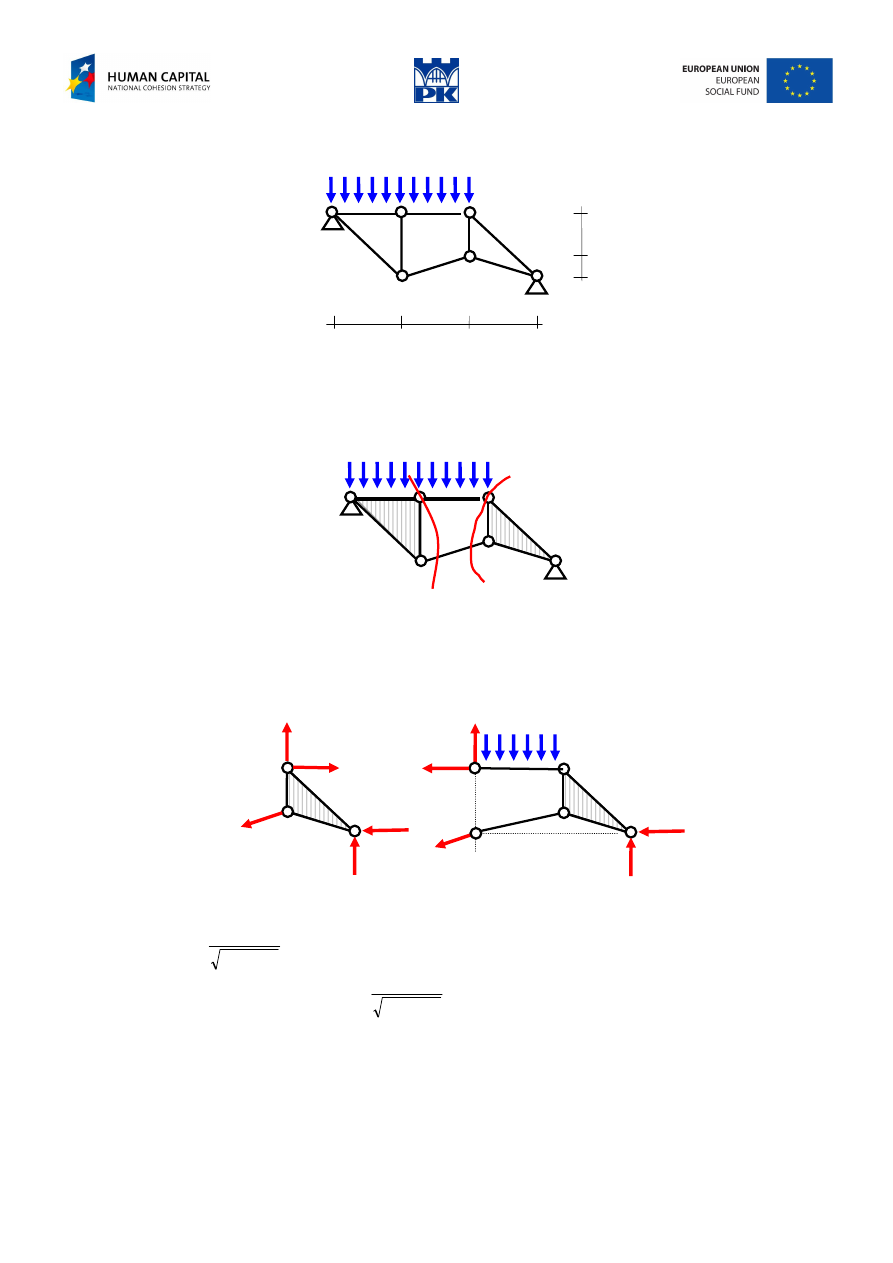
Free-body unstable structure
1
2
3
3
3
Fig. 12.6 Free-body unstable structure
First, we distinguish the beam elements. Analysis of geometric stability suggests the main idea of the
solution. Leaving the shields of three elements “untouched”, we cut the structure through the hinges and
the same truss element, Fig. 12.7.
Fig. 12.7 Beam elements and suggested sections
For the entire structure we have:
∑
=
⋅
+
⋅
−
⋅
⋅
→
=
0
3
9
3
6
35
0
B
B
A
H
V
M
For the structure parts, Fig. 12.8, we have:
C
D
C
N
H
B
V
B
α-α
N
H
B
V
B
β-β
Fig. 12.8 Reactions calculation
0
3
3
5
.
0
3
3
2
0
2
2
=
⋅
−
⋅
+
+
⋅
⋅
→
=
∑
B
B
C
V
H
N
M
0
5
.
0
3
3
3
6
3
5
.
1
3
35
0
2
2
=
+
⋅
⋅
+
⋅
−
⋅
+
⋅
⋅
→
=
∑
N
V
H
M
B
B
D
We get the system of equations:
25
.
26
75
.
78
85
.
79
5
.
157
0
630
3
6
959
.
2
3
3
973
.
1
3
9
0
=
=
=
→
−
−
=
•
−
−
−
B
B
B
B
H
V
N
H
V
N
We compute the constraints reactions, the axial forces in truss bars and consider the beam elements,
obtaining all data needed to construct the cross-section forces diagrams.
Adam Paweł Zaborski
Project “The development of the didactic potential of Cracow University of Technology in the range of
modern construction” is co-financed by the European Union within the confines of the European Social Fund
and realized under surveillance of Ministry of Science and Higher Education.
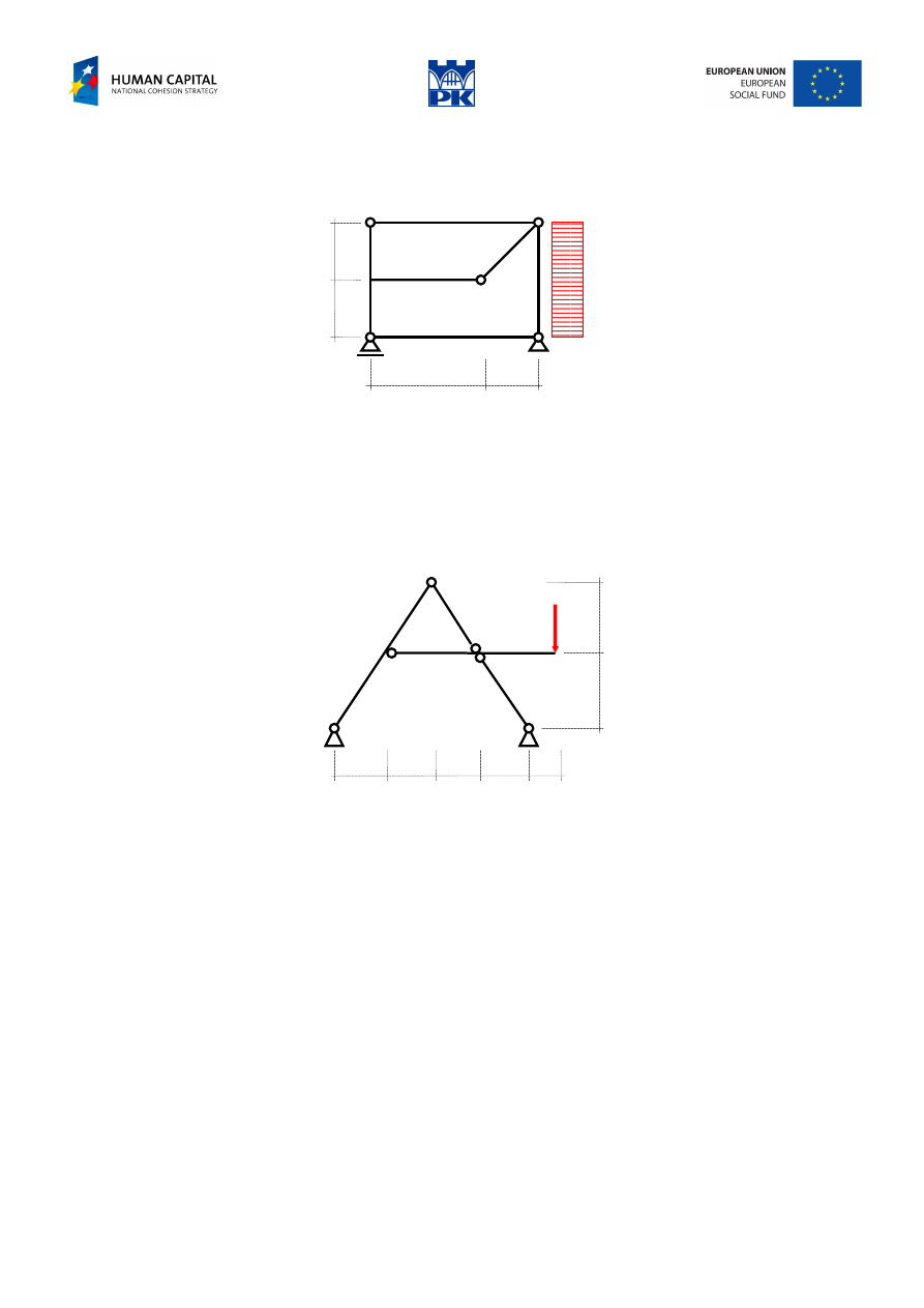
Workshop theme
Determine the cross-section forces of the structures in Fig. 12.9 and Fig. 12.10 and draw their diagrams.
a)
q
b
b
a
a/2
Fig. 12.9 Free-body stable structure
Input data:
a
= ……. m (2
÷5 m)
b
= ……. m (1
÷3 m)
q
= ……. kN/m (5
÷50 kN/m)
b)
a/2
P
b
b
a
a
a
a
Fig. 12.10 Free-body unstable structure
Input data:
a
= ……. m (1,5
÷4 m)
b
= ……. m (2
÷6,5 m)
P
= ……. kN (100
÷400 kN)
Adam Paweł Zaborski
Project “The development of the didactic potential of Cracow University of Technology in the range of
modern construction” is co-financed by the European Union within the confines of the European Social Fund
and realized under surveillance of Ministry of Science and Higher Education.
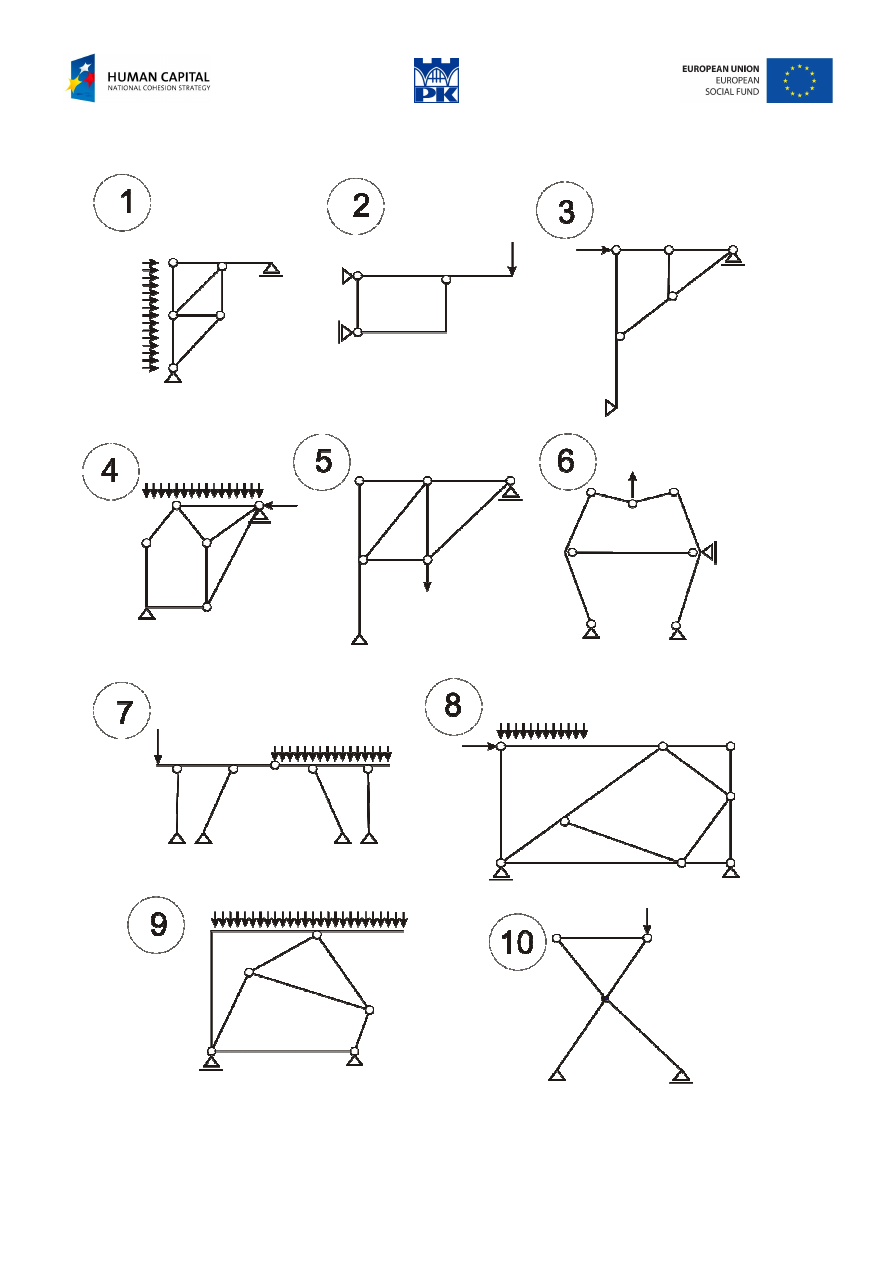
Review problems
Fig. 12.11 Review problems
Adam Paweł Zaborski
Project “The development of the didactic potential of Cracow University of Technology in the range of
modern construction” is co-financed by the European Union within the confines of the European Social Fund
and realized under surveillance of Ministry of Science and Higher Education.
Addendum
Hints
The algebra of a solution can be simplified by the choice of a moment axis which eliminates as many
unknowns as possible or by the choice of a direction for a force summation which avoids reference to
certain unknowns. A few moments of thought to take advantage of these simplifications can save
appreciable time and effort.
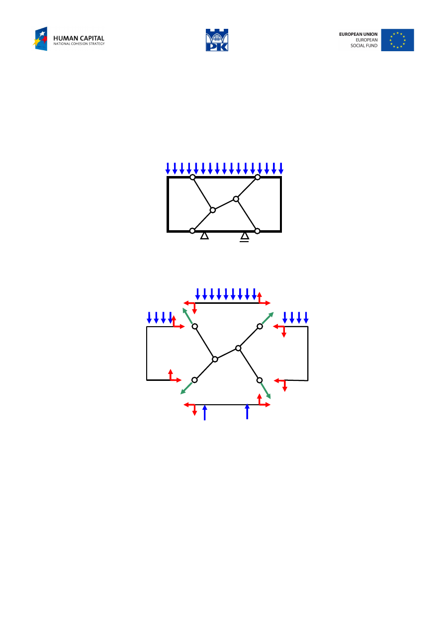
In extremely difficult cases or when we have no clear idea of the solution procedure, we can break up the
structure into separate elements and write the balance equations for them, Fig. 12.12.
Fig. 12.12 Structure with the truss bars “inside” the beam bars
We get four beam elements and five truss elements, Fig. 12.13.
Fig. 12.13 Decomposition of the structure
We have four shields, five bars and three reactions, thus:
24
3
5
4
4
=
+
+
⋅
unknowns. We have three
equations for each shield and two equations for each hinge, so
24
2
6
3
4
=
⋅
+
⋅
equations.
Glossary
beam element – element belkowy
truss element – element kratowy
Wyszukiwarka
Podobne podstrony:
C07 design 12 AZ
C07 design 11 AZ
C07 design 08 AZ
C07 design 02 AZ
C07 design 03 AZ
C07 design 09 az
C07 design 05 AZ
C07 design 10 AZ
C07 design 06 AZ
C07 design 01 AZ
C07 design 03 AZ
C07 design 02 AZ
C07 design 09 AZ
C07 design 10 AZ
C07 design 01 AZ
C07 design 06 AZ
C07 design 08 AZ
C07 design 15 AZ
C07 design 14 AZ
więcej podobnych podstron