
Joe Flynn's Parallel Path Magnetic Technology
Tim Harwood © 2003
There is a widespread opinion common to the mainstream academic community and also to various
alternative scientific forums, that some kind of exotic new physics will be required to design and
implement over-unity technologies. That is to say electrical motors, electrical generators, or other
apparatus, which produce an excess of magnetic force or energy above the value actually inputted.
However, this has recently been experimentally demonstrated not to be the case, as I have validated
myself in simple $20 experiments undertaken at home with parts bought from the local hardware
store. It is the purpose of this article to educate readers that with care, thought, and a little work, it
can be demonstrated that existing textbook physical law, freely allows for the extraction of excess
electrical energy from magnetic systems.
The credit for this ground breaking research goes to Joe Flynn, who has been engaged in magnetic
flux research for over 25 years now. His work is long standing, comprehensive, and in later years,
well funded. It is reported $7m has been spent to date, with over $1m alone developing a
revolutionary high performance magnetic motor. His equipment is validated, and apparently already
in mass production for select customers. Since many lines of research have been formulated and
explored by Joe Flynn, the following article presents only a brief summary of some of his best art
apparatus, but is nonetheless sufficient to convey the basic ideas, and provide a framework within
which one can undertake experiments.
Principals of Operation
The first illustration Figure 1 is taken from Joe Flynn's US patent 6,246,561, and explains a simple
magnetic force multiplication experiment, which forms the basis for the Flynn magnetic art. If the
windings on either side of the central magnet, which are normally connected in series, are properly
pulsed, the field of the permanent magnet in the center, will be diverted to the opposite side of the
core flux path provided. Or in alternative language, the side of the core that is pulsed, is
demagnetized, relative to the field of the permanent magnet used in the apparatus. This is
elementary textbook physics anyone can understand.
So what is surprising about this apparently simple apparatus, is that the armature on the side of the
flux core, will contain 1.75 times more units of magnetic force, than could be manifested by the
electrical input to the apparatus alone. Since the ability to arbitrarily move force from one point to
another is the basis for motion or work, however simplistic, we therefore have a basis for a system
that can be developed for practical technological purposes. Expressed in alternative language, we
also have the capability to engineer a time varying magnetic field, without the need for moving
parts, which will allow development of systems that output electrical energy. Both capabilities are
highly desirable, and offer substantial opportunity for technical development.

Expanding upon this basic experiment, there is a second simple and logical improvement in layout
illustrated in Figure 2, which should be obvious, but has been shown not to be the case. In this
instance, the pulse is centrally located, and a dual flux field layout employed, which both
demagnetizes the core relative to one magnet, and magnetizes it relative to the other. Since the two
actions are complementary, the input required to manifest the flux switching effect is halved,
therefore doubling 'efficiency.'
It should be noted that while the efficiency is doubled, the absolute output may not be significantly
improved. This is because the major weakness of this effect and technology is flux saturation of the
core, with values depending upon the specific properties of the B-H curve of the core material
employed, limiting the absolute output of both layouts the same.
The previous statements are not required to be taken on trust, and simple experiments have been
proposed by Joe Flynn, such that anyone can validate this effect for themselves. Figure 3 is a simple
experiment taken from the Flynn website, that can be used to validate the principals put forward in
this article.
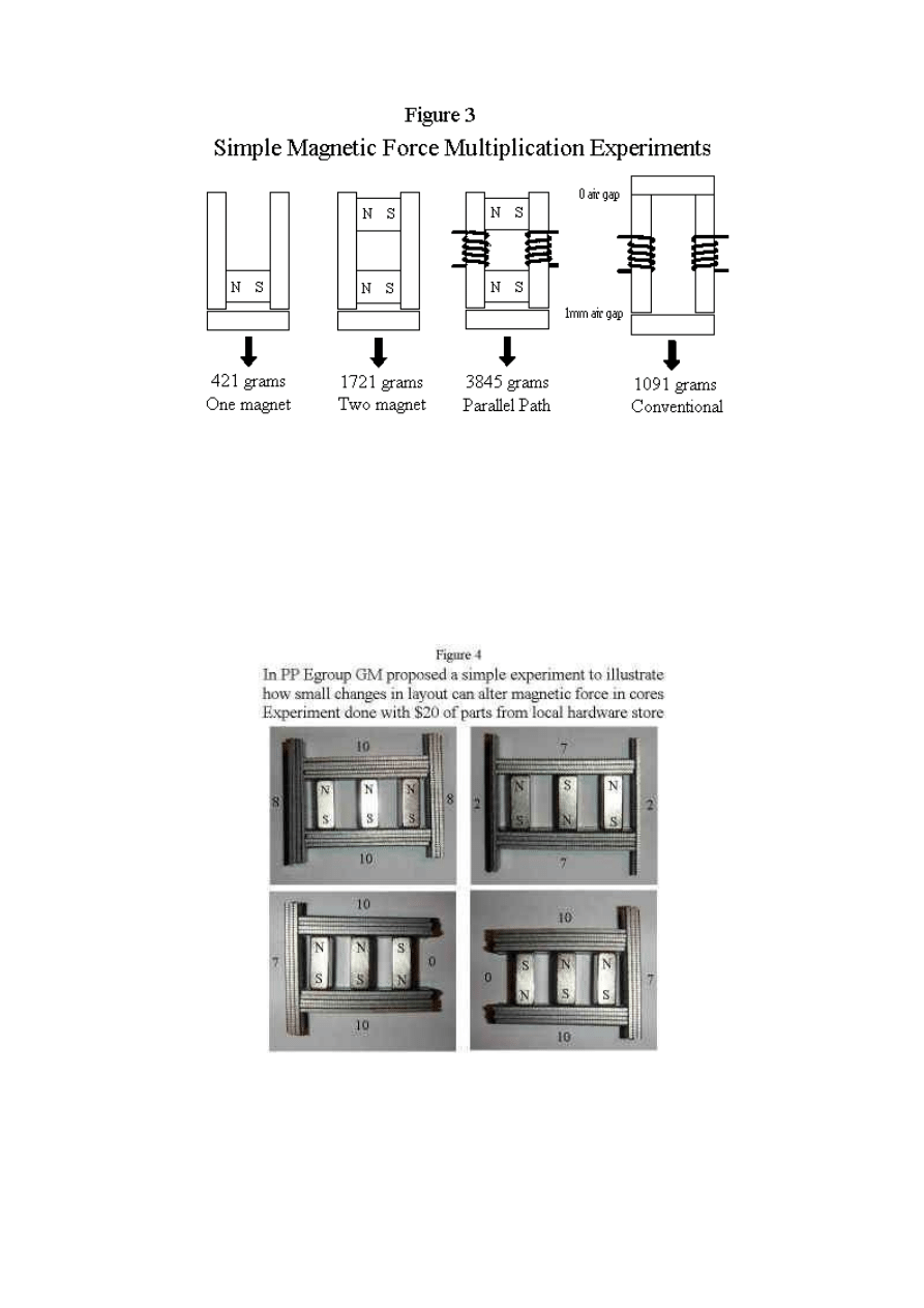
An even simpler non electrical flux experiment was proposed by GM in the Parallel Path Egroup.
My apparatus is illustrated in Figure 4. It is no more than magnets and steel staple strips, bought
from a local hardware store for a total of under $10. The Parallel Path effect can be replicated with
identical apparatus, at only a slight increase in cost and complexity, with the addition of a simple
12v polarity reversible power supply, such as those commonly sold to power computer speakers,
among other household applications.
Conservation of Energy / Field Potential
One of the aspects of the Flynn technology people find most difficult to understand, is how you can
have a device that delivers 3.47 times more units of magnetic force than is electrically inputted, yet
not violate accepted principals of text book physics, as stated in the introduction. The key point here
is magnetic fields do not gain energy - they are conservative. You can only ever obtain less energy
from a magnetic field minus looses, than is in fact present. I feel this apparent puzzle can not be
better explained, than by reference to Joe Flynn's own analysis of the experiment presented in
Figure 3.
'Since the Parallel Path System produced 3.47 times more force than the conventional system, with
the same electrical input, it appears to violate conservation, this is only true when observed from a
traditional view point. The system contains three flux producing sources (2 magnets and an
electromagnet) which together are capable of producing a far greater force than is actually
produced. All of the flux sources together can produce a force of 13.11 units, therefore in the
physical sense a loss of 1 - (9.01 / 13.11) = 31% is realized.'
So the system is 347 % efficient, in terms of delivered magnetic force compared to net electrical
input, yet still conforms to the accepted physical principals of field conversation, by being only 69
% efficient, in terms of the fields present in the system. However surprising this result may appear,
the analysis presented is in outline correct, with the difference between fields present in the system,
and net electrical input, being the important concept presented.
Losses in the System
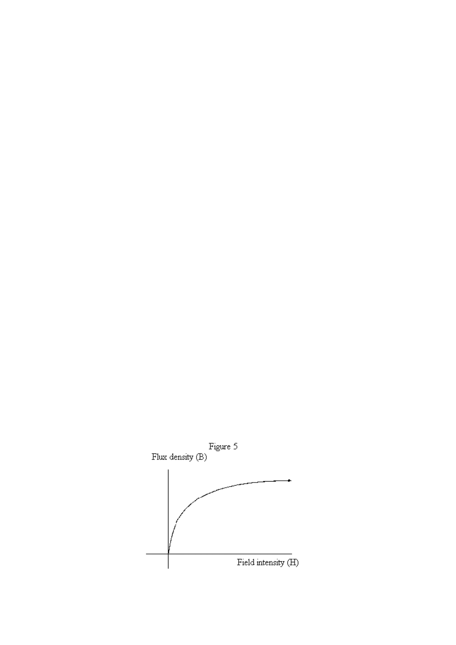
In order to optimise flux cores, an appreciation of the physics that underlies the transfer of flux
within a core is required. The normal magnetization curve, or B-H curve, is a mathematical
relationship between applied field intensity H, and resultant flux density manifested in the core B. It
varies according to core material, and the curve will shift, if there is a starting magnetism within the
core, such as that provided by the field of a permanent magnet. If the start magnetism is excessive,
the core is saturated, and will not properly respond to the applied force H. A simple B-H curve is
illustrated in Figure 5.
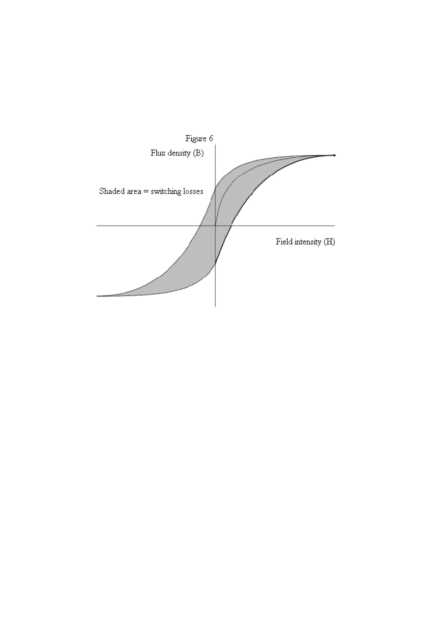
Hysteresis is a delay between applied magnetic force H, and resultant flux density B, that again
varies according to material type. It also manifests as a delay between the termination of force H,
and the manifestation of flux density B. So, the system will not turn on instantly, and will not turn
off instantly, in simple terms. This is because the magnetic memory of the core, means a flux vector
remains within it, even when the application of magnetic force H has been terminated. If we apply a
reversed force H to the core, the basic B-H curve is now expanded as in Figure 6, with the memory
effect also illustrated.
In order to return to the initial switched state, the remnance magnetism must now be overcome,
hence input once in operation, will be greater than that required for the very first pulse. The area
within the hysteresis curve gives a rough estimate for the amount of wasted energy, and along with
other conventional sources of losses resultant in flux transfer within a core, is what reduces the
efficiency of flux cores from maximum values of 2, or 4, down to values such as 1.75 or 3.47,
typically.
Motor Apparatus
Although numerous practical applications abound for this effect, electric motor design remains the
most outstanding opportunity. To this extent, again a few simple images, should be sufficient to
explain how the basic flux switching apparatus, can be turned into a highly efficient electrical
motor.
The first motor shown in Figure 7 is one I have proposed to validate the flux switching effect at a
most basic level. It illustrates the point made in the Flynn patent, that the armature of the core can
be removed, and replaced with a motor flux path. This first motor is not claimed to be highly
efficient, but it helps one to understand how the transition from simple flux core to motor takes
place.
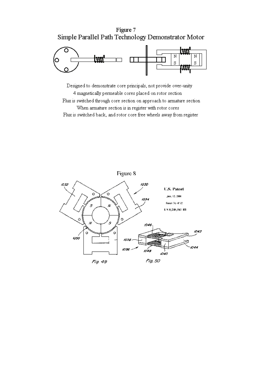
The next motor shown in Figure 8 is again taken directly from the Flynn patent, and illustrates the
next intermediate step to motor design. The fields of the permanent magnets are alternatively
switched from one side of the surrounding flux cores to the other, alternately interacting with N and
S poles on the rotor, imparting motion to the central rotor shaft.
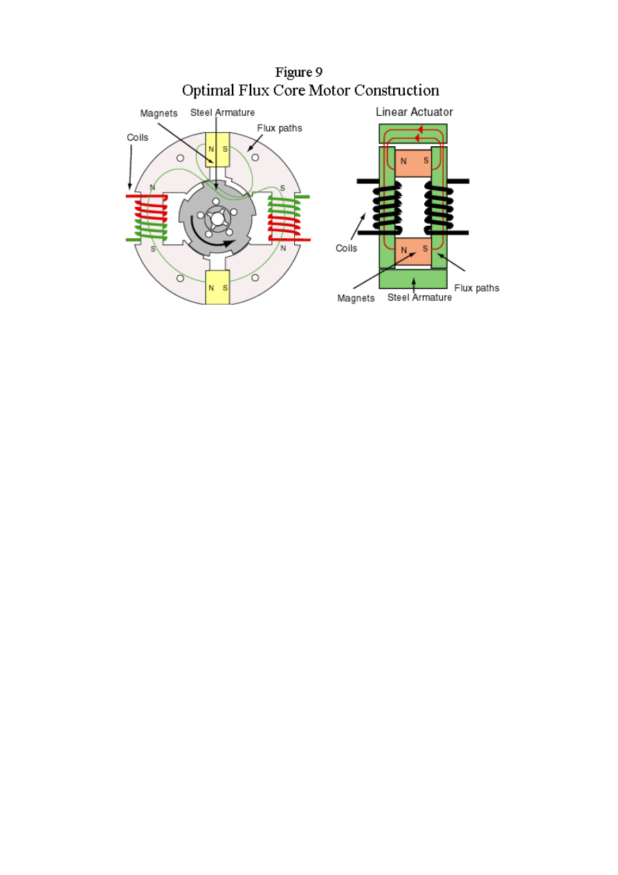
With proper financial support, and the facilities to have metglas cores custom moulded, Joe Flynn
was able to develop his final best art, shown in Figure 9. No detailed performance numbers have
been released for this motor, whose precise characteristics remain proprietary to Joe Flynn at this
time. But the optimisation is so expert, it is stated to posses certain exotic properties, such as cool
ambient operation, even during prolonged periods of continuous load. This 'cold running' is said to
be of great interest to the American military, as it offers excellent stealth performance
characteristics.
Electrical Apparatus
Many readers will no doubt have noticed the similarity of the first illustration presented in this
document, to the so called 'Tom Bearden MEG.' This is fair comment, and Joe Flynn has always
highlighted this issue. However, it has been commonly stated Joe Flynn simply developed
mechanical apparatus, and the MEG with its electrical functionality, is distinct art, more advanced
than the mechanical Flynn apparatus. However, this is shown not to be the case by a careful
examination of the Flynn patent, in which the following is stated in the 'Power Conversion' section:
'The construction shown in FIG. 45A utilizes four control coils and a single permanent magnet and
the construction shown in FIG. 45X uses two control coils and two permanent magnets. The flux
that would normally be supplied by a primary winding is supplied by the static flux of the
permanent magnet or magnets and the control coils convert this static flux into a time varying flux
in a novel way. Both arrangements use two secondary coils, the secondary coils are placed in the
region of the continuous flux path that would be occupied by an armature or rotor in the linear or
rotary arrangements. The regions of the flux paths that perform work are the same in all cases.'
'By alternating the polarity of the control coils during one cycle, one working region experiences an
increasing flux and the opposite region experiences a decreasing flux and during the next cycle the
opposite occurs. This results in the induction of a voltage in the secondary coils that is decided by
the magnitude of the change in flux in the working region and the time in which this change occurs.
The novelty of this discovery is that the primary flux inducing the voltage in the secondary coils is
supplied by the permanent magnet or magnets and is far greater than the flux supplied by the
control coils.'
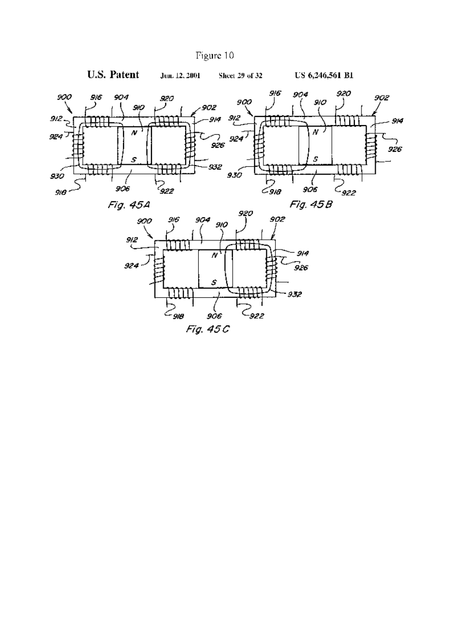
Figure 10 taken directly from the Flynn patent makes the point even clearer. Joe Flynn has also
stated that his intellectual property rights will be robustly defended, by legal action if necessary, and
he regards himself and his company as being in possession of exclusive rights to the so called
'MEG' unit.
As regards replication of electrical output orientated flux core devices, certain important details
need to be stated. For example grade 8 ceramic magnets should be used, so as to avoid flux
saturation of the core. A basic error, many early experimenters wasted time on. The requirement for
strong magnets to obtain over-unity results, is as much of a myth, as the idea new physics is
required.
But perhaps the greatest trade secret of the electrical devices, one which several lengthy non
disclosure agreements are required to be signed before it can be disclosed, is that the input and
output circuits must be closed in series. The disclosure of this technique, amounts to putting the
basic MEG methodology fully into the public domain.
The reason for this circuitry requirement is obvious enough, with only a little analysis. If the output
circuit is closed when the input circuit is activated, then the input energy simply leaks into the
output circuit, as in an ordinary transformer. So no flux switching effect is manifested, and the field
of the permanent magnet is static in time. Thus you have an ordinary transformer, with reduced
efficiency, because of the core flux saturation effect provided by the permanent magnet.
This is one of the most important points to make about the Flynn apparatus. If you approach it as if
it is a normal piece of scientific equipment, then proper optimisation is not greatly problematic. For

example more turns on the output coils, simply means more voltage and less current, exactly as
standard textbook equations predict. Increased input voltage enables faster switching speeds, a
consequent greater rate of change of magnetic flux, resulting in higher absolute output, but only up
to the flux saturation limit of the core material. Generally, problems only occur, if you imagine the
effect is based upon exotic scalar type or vacuum energy physics, when in fact it is ordinary flux
manipulation within a core.
Present Status of the Flynn Project
Initially Joe Flynn was remarkably open about his work and research. However, since performing a
working demonstration of various advanced hardware samples for the American Department of
Defence, little has been heard.
I want to clearly emphasize I do not speak for Flynn Research, nor am I in any way connected with
Flynn Research, and by consequence, have no inside information whatsoever as to the present status
of the project. But we all sincerely hope, that the project has not been swallowed whole by the
American deep black military industrial research complex.
However, even if this is the case, it does not mean the technology is lost. Extensive and generous
details have been provided by Joe Flynn of his research, both in his patent deposition, website, and
other comments, such as to enable persons of scientific training and skill, to replicate the effects
stated.
While replication of the electrical effect remains extremely demanding, the mechanical apparatus is
very easy both to understand and replicate. There is no reason why professional scientists and home
experimenters alike, can not build Flynn type flux core motors, and explore over-unity flux
manipulation for themselves. The future has already arrived, and it is simpler and cheaper than
anyone dared imagine to be possible.
References
http://www.flynnresearch.net/
, Flynn website
http://www.rexresearch.com/meg/meg.htm
, MEG US patent 6,362,718
Wyszukiwarka
Podobne podstrony:
TECHNOLOGIA MAGNETYCZNYCH RÓWNOLEGŁYCH ŚCIEŻEK JOE EGO FLYNNA
Technologia spawania stali wysokostopowych 97 2003
TECHNOLOGIA ROBOT word 2003, Pytania i materiały na kurs
Ściągi z fizyki-2003 r, Odziaływanie pola magnetycznego na organizmy żywe
Ściągi z fizyki-2003 r, Odziaływanie pola magnetycznego na organizmy żywe
(),materiały zaawansowane technologicznie L, Zagadnienia podatność magnetyczna
ACETANILID, technologia chemiczna, chemia organiczna 2003,2004
NITROANILINY, technologia chemiczna, chemia organiczna 2003,2004
[2003] Constant Voltage Permanent Magnet Wind Generator
Technologia magnetyczna MAD?vice
Ściągi z fizyki-2003 r, Magnetyzm
Estry metylowe podstawionych kwasów benzoesowych, technologia chemiczna, chemia organiczna 2003,2004
chem zyw sciagi 2003, POLITECHNIKA ŁÓDZKA, Technologia Żywności i Żywienia Człowieka, semestr 4, Che
Ściągi z fizyki-2003 r, Pole magnetyczne ziemi
ZWIĄZKI NATURALNE, technologia chemiczna, chemia organiczna 2003,2004
SYNTEZA GRIGNARDA, technologia chemiczna, chemia organiczna 2003,2004
Ściągi z fizyki-2003 r, Faraday i magnetyzm
Ściągi z fizyki-2003 r, Hertz i magnetyzm
Instrukcja technologiczna produkcji soku pitnego z czarnych porzeczek 2003
więcej podobnych podstron