
TABLE OF CONTENTS
INTRODUCTION . . . . . . . . . . . . . . . . . . . . . . . . . . . . . . . . . . . . . . . . . . . . . . . . . . . . . . . . .1
SYSTEM COVERAGE . . . . . . . . . . . . . . . . . . . . . . . . . . . . . . . . . . . . . . . . . . . . . . .1
SIX-STEP TROUBLESHOOTING PROCEDURE . . . . . . . . . . . . . . . . . . . . . . . . . .1
IDENTIFICATION OF SYSTEM . . . . . . . . . . . . . . . . . . . . . . . . . . . . . . . . . . . . . . . . . . . . .1
SYSTEM DESCRIPTION AND FUNCTIONAL OPERATION . . . . . . . . . . . . . . . . . . . . . .1
TEVES MARK 20e SYSTEM DESCRIPTION . . . . . . . . . . . . . . . . . . . . . . . . . . . . .1
TRACTION CONTROL SYSTEM (TCS) DESCRIPTION (IF EQUIPPED) . . . . . . .1
SYSTEM COMPONENTS . . . . . . . . . . . . . . . . . . . . . . . . . . . . . . . . . . . . . . . . . . . . .2
ABS AND BRAKE WARNING INDICATORS . . . . . . . . . . . . . . . . . . . . . .2
CONTROLLER ANTILOCK BRAKE (CAB) . . . . . . . . . . . . . . . . . . . . . . .2
HYDRAULIC CONTROL UNIT . . . . . . . . . . . . . . . . . . . . . . . . . . . . . . . . .2
ABS SWITCHES/SENSORS. . . . . . . . . . . . . . . . . . . . . . . . . . . . . . . . . . .3
ABS INITIALIZATION . . . . . . . . . . . . . . . . . . . . . . . . . . . . . . . . . . . . . . . .3
ABS DIAGNOSTIC MODE . . . . . . . . . . . . . . . . . . . . . . . . . . . . . . . . . . . .3
TRACTION CONTROL OPERATION (IF EQUIPPED) . . . . . . . . . . . . . .4
DIAGNOSTIC TROUBLE CODES . . . . . . . . . . . . . . . . . . . . . . . . . . . . . . . . . . . . . .4
FREEZE FRAME . . . . . . . . . . . . . . . . . . . . . . . . . . . . . . . . . . . . . . . . . . . . . . . . . . . .4
ERROR MESSAGES AND BLANK SCREEN . . . . . . . . . . . . . . . . . . . . . .4
DOES NOT POWER UP. . . . . . . . . . . . . . . . . . . . . . . . . . . . . . .4
DISPLAY IS NOT VISIBLE . . . . . . . . . . . . . . . . . . . . . . . . . . . . . . . . . . . .4
DISCLAIMERS, SAFETY, WARNINGS . . . . . . . . . . . . . . . . . . . . . . . . . . . . . . . . . . . . . . .4
DISCLAIMERS. . . . . . . . . . . . . . . . . . . . . . . . . . . . . . . . . . . . . . . . . . . . . . . . . . . . . .4
SAFETY . . . . . . . . . . . . . . . . . . . . . . . . . . . . . . . . . . . . . . . . . . . . . . . . . . . . . . . . . . .5
TECHNICIAN SAFETY INFORMATION . . . . . . . . . . . . . . . . . . . . . . . . . .5
VEHICLE PREPARATION FOR TESTING . . . . . . . . . . . . . . . . . . . . . . . .5
SERVICING SUB-ASSEMBLIES . . . . . . . . . . . . . . . . . . . . . . . . . . . . . . .5
SAFETY INFORMATION . . . . . . . . . . . . . . . . . . . . . . . . . . . . . .5
WARNINGS . . . . . . . . . . . . . . . . . . . . . . . . . . . . . . . . . . . . . . . . . . . . . . . . . . . . . . . .6
VEHICLE DAMAGE WARNINGS . . . . . . . . . . . . . . . . . . . . . . . . . . . . . . .6
ROAD TESTING A COMPLAINT VEHICLE . . . . . . . . . . . . . . . . . . . . . . .6
DIAGNOSIS . . . . . . . . . . . . . . . . . . . . . . . . . . . . . . . . . . . . . . . . . . . . . . . . . . . . . . . .6
REQUIRED TOOLS AND EQUIPMENT . . . . . . . . . . . . . . . . . . . . . . . . . . . . . . . . . . . . . .7
GLOSSARY OF TERMS. . . . . . . . . . . . . . . . . . . . . . . . . . . . . . . . . . . . . . . . . . . . . . . . . . .7
DIAGNOSTIC INFORMATION AND PROCEDURES . . . . . . . . . . . . . . . . . . . . . . . . . . . .9
ADJUSTABLE PEDALS
INTERNAL CONTROLLER ERROR. . . . . . . . . . . . . . . . . . . . . . . . . . . . . . . . . . . . . . . . .10
PEDAL SENSOR OPEN/SHORTED TO GROUND . . . . . . . . . . . . . . . . . . . . . . . . . . . . .11
PEDAL SENSOR SHORTED TO BATTERY . . . . . . . . . . . . . . . . . . . . . . . . . . . . . . . . . .14
PEDAL SW STUCK FORWARD. . . . . . . . . . . . . . . . . . . . . . . . . . . . . . . . . . . . . . . . . . . .16
PEDAL SW STUCK REARWARD . . . . . . . . . . . . . . . . . . . . . . . . . . . . . . . . . . . . . . . . . .18
SYSTEM OVER VOLTAGE. . . . . . . . . . . . . . . . . . . . . . . . . . . . . . . . . . . . . . . . . . . . . . . .20
SYSTEM UNDER VOLTAGE . . . . . . . . . . . . . . . . . . . . . . . . . . . . . . . . . . . . . . . . . . . . . .22
*CAN’T ADJUST PEDALS . . . . . . . . . . . . . . . . . . . . . . . . . . . . . . . . . . . . . . . . . . . . . . . .24
*CAN’T SET/RECALL MEMORY POSITIONS . . . . . . . . . . . . . . . . . . . . . . . . . . . . . . . . .29
i

TABLE OF CONTENTS - Continued
BRAKES (CAB)
BUS SYSTEM COMMUNICATION FAILURE . . . . . . . . . . . . . . . . . . . . . . . . . . . . . . . . .31
CAB INTERNAL FAILURE . . . . . . . . . . . . . . . . . . . . . . . . . . . . . . . . . . . . . . . . . . . . . . . .33
CLUSTER LAMP FAILURE. . . . . . . . . . . . . . . . . . . . . . . . . . . . . . . . . . . . . . . . . . . . . . . .35
INCORRECT TONE WHEEL FAILURE . . . . . . . . . . . . . . . . . . . . . . . . . . . . . . . . . . . . . .37
LEFT FRONT SENSOR CIRCUIT FAILURE . . . . . . . . . . . . . . . . . . . . . . . . . . . . . . . . . .38
LEFT REAR SENSOR CIRCUIT FAILURE . . . . . . . . . . . . . . . . . . . . . . . . . . . . . . . . . . .38
RIGHT FRONT SENSOR CIRCUIT FAILURE . . . . . . . . . . . . . . . . . . . . . . . . . . . . . . . . .38
RIGHT REAR SENSOR CIRCUIT FAILURE . . . . . . . . . . . . . . . . . . . . . . . . . . . . . . . . . .38
LEFT FRONT WHEEL SPEED SIGNAL FAILURE . . . . . . . . . . . . . . . . . . . . . . . . . . . . .43
LEFT REAR WHEEL SPEED SIGNAL FAILURE . . . . . . . . . . . . . . . . . . . . . . . . . . . . . .43
RIGHT FRONT WHEEL SPEED SIGNAL FAILURE . . . . . . . . . . . . . . . . . . . . . . . . . . . .43
RIGHT REAR WHEEL SPEED SIGNAL FAILURE . . . . . . . . . . . . . . . . . . . . . . . . . . . . .43
PUMP CIRCUIT FAILURE . . . . . . . . . . . . . . . . . . . . . . . . . . . . . . . . . . . . . . . . . . . . . . . .46
SYSTEM OVER VOLTAGE. . . . . . . . . . . . . . . . . . . . . . . . . . . . . . . . . . . . . . . . . . . . . . . .50
SYSTEM UNDER VOLTAGE . . . . . . . . . . . . . . . . . . . . . . . . . . . . . . . . . . . . . . . . . . . . . .53
VALVE POWER FEED FAILURE . . . . . . . . . . . . . . . . . . . . . . . . . . . . . . . . . . . . . . . . . . .55
*BRAKE LAMP SWITCH INOPERATIVE . . . . . . . . . . . . . . . . . . . . . . . . . . . . . . . . . . . . .58
*TRAC OFF INDICATOR NEVER/ALWAYS ON . . . . . . . . . . . . . . . . . . . . . . . . . . . . . . .59
*TRAC ON INDICATOR NEVER/ALWAYS ON . . . . . . . . . . . . . . . . . . . . . . . . . . . . . . . .62
COMMUNICATION
*NO RESPONSE FROM ADJUSTABLE PEDALS ASSEMBLY . . . . . . . . . . . . . . . . . . .63
*NO RESPONSE FROM CONTROLLER ANTILOCK BRAKE . . . . . . . . . . . . . . . . . . . .65
VERIFICATION TESTS
VERIFICATION TESTS . . . . . . . . . . . . . . . . . . . . . . . . . . . . . . . . . . . . . . . . . . . . . . . . . . .67
COMPONENT LOCATIONS . . . . . . . . . . . . . . . . . . . . . . . . . . . . . . . . . . . . . . . . . . . . . . .69
CONTROLLER ANTILOCK BRAKE (CAB) . . . . . . . . . . . . . . . . . . . . . . . . . . . . . .69
DATA LINK CONNECTOR . . . . . . . . . . . . . . . . . . . . . . . . . . . . . . . . . . . . . . . . . . .69
FUSES . . . . . . . . . . . . . . . . . . . . . . . . . . . . . . . . . . . . . . . . . . . . . . . . . . . . . . . . . . .69
TRACTION CONTROL SWITCH . . . . . . . . . . . . . . . . . . . . . . . . . . . . . . . . . . . . . .70
TRACTION CONTROL INDICATORS . . . . . . . . . . . . . . . . . . . . . . . . . .70
WHEEL SPEED SENSORS . . . . . . . . . . . . . . . . . . . . . . . . . . . . . . . . . . . . . . . . . .70
FRONT. . . . . . . . . . . . . . . . . . . . . . . . . . . . . . . . . . . . . . . . . . . . . . . . . . .70
REAR . . . . . . . . . . . . . . . . . . . . . . . . . . . . . . . . . . . . . . . . . . . . . . . . . . . .71
8.5A WHEEL SPEED SENSOR CONNECTORS. . . . . . . . . . . . . . . . . . . . . . . . . . . . . .71
8.5A.1 FRONT. . . . . . . . . . . . . . . . . . . . . . . . . . . . . . . . . . . . . . . . . . . . . . . . . . .71
8.5A.2 REAR . . . . . . . . . . . . . . . . . . . . . . . . . . . . . . . . . . . . . . . . . . . . . . . . . . . .71
BRAKE LAMP SWITCH . . . . . . . . . . . . . . . . . . . . . . . . . . . . . . . . . . . . . . . . . . . . .72
CONNECTOR PINOUTS . . . . . . . . . . . . . . . . . . . . . . . . . . . . . . . . . . . . . . . . . . . . . . . . .73
ABS PUMP MOTOR (COMPONENT SIDE) - 2 WAY . . . . . . . . . . . . . . . . . . . . . . . . . . .73
BRAKE LAMP SWITCH - BLACK 6 WAY . . . . . . . . . . . . . . . . . . . . . . . . . . . . . . . . . . . .73
CONTROLLER ANTILOCK BRAKE - BLACK 24 WAY . . . . . . . . . . . . . . . . . . . . . . . . . .74
DATA LINK CONNECTOR - BLACK 16 WAY . . . . . . . . . . . . . . . . . . . . . . . . . . . . . . . . .74
FUSES (IPM) . . . . . . . . . . . . . . . . . . . . . . . . . . . . . . . . . . . . . . . . . . . . . . . . . . . . . . . . . . .76
LEFT FRONT WHEEL SPEED SENSOR - GRAY 2 WAY . . . . . . . . . . . . . . . . . . . . . . .76
LEFT REAR WHEEL SPEED SENSOR - BLACK 2 WAY. . . . . . . . . . . . . . . . . . . . . . . .77
RIGHT FRONT WHEEL SPEED SENSOR - GRAY 2 WAY . . . . . . . . . . . . . . . . . . . . . .77
RIGHT REAR WHEEL SPEED SENSOR - BLACK 2 WAY . . . . . . . . . . . . . . . . . . . . . .77
ii

TABLE OF CONTENTS - Continued
SCHEMATIC DIAGRAMS. . . . . . . . . . . . . . . . . . . . . . . . . . . . . . . . . . . . . . . . . . . . . . . . .79
10.1 TEVES MARK 20E ANTILOCK BRAKE SYSTEM – ABS . . . . . . . . . . . . . . . . . . .79
iii

NOTES
iv

1.0
INTRODUCTION
The procedures contained in this manual include
all the specifications, instructions, and graphics
needed to diagnose the 2005 Chrysler Town &
Country, Dodge Caravan, and Chrysler Voyager
Mark 20e Antilock Braking System (ABS), and
Mark 20e Antilocke Braking System with Traction
Control. The diagnostics in this manual are based
on the failure condition or symptom being present
at time of diagnosis.
Please follow the recommendations below when
choosing your diagnostic path.
1. First make sure the DRBIII
t is communicating
with the CAB. If the DRBIII
t displays a “No
Response” condition, you must diagnose that
first.
2. Read DTC’s (diagnostic trouble codes) with the
DRBIII
t.
3. If no DTC’s are present, identify the customer
complaint.
4. Once the DTC or customer complaint is identi-
fied, locate the matching test in the Table of
Contents and begin to diagnose the symptom.
All component location views are in Section 8.0.
All connector pinouts are in Section 9.0. All sche-
matics are in Section 10.0.
An asterisk (*) placed before the symptom descrip-
tion indicates a concern with no associated DTC.
When repairs are required, refer to the appropri-
ate service manual for the proper removal and
repair procedure.
Diagnostic procedures change every year. New
diagnostic systems may be added; carry over sys-
tems may be enhanced. READ THIS MANUAL
BEFORE TRYING TO DIAGNOSE A VEHICLE
CODE. It is recommended that you review the
entire manual to become familiar with all new and
changed diagnostic procedures.
After using this book, if you have any comments
or recommendations, please fill out the form at the
back of the book and mail it back to us.
1.1
SYSTEM COVERAGE
This diagnostic procedure manual covers the an-
tilock braking system (ABS), and the traction con-
trol system found on: Chrysler Town and Country,
Dodge Caravan, and Chrysler Voyager.
1.2
SIX-STEP TROUBLESHOOTING
PROCEDURE
Diagnosis of the controller antilock brake module
is done in six basic steps:
•
verification of complaint
•
verification of any related symptoms
•
symptom analysis
•
problem isolation
•
repair of isolated problem
•
verification of proper operation
2.0
IDENTIFICATION OF
SYSTEM
Vehicles equipped with the Teves Mark 20e an-
tilock brake system can be identified by the pres-
ence of the controller antilock brake module located
beneath the master cylinder.
The presence of the Traction Control system is
indicated by the TRAC OFF switch on top of the
steering column shroud.
3.0
SYSTEM DESCRIPTION AND
FUNCTIONAL OPERATION
3.1
TEVES MARK 20e SYSTEM
DESCRIPTION
The controller antilock brake module is used to
monitor wheel speeds and to modulate (control)
hydraulic pressure in each brake channel. The
modulated hydraulic pressure is used to prevent
wheel lock-up during braking.
The Teves Mark 20e system uses a diagonal split
hydraulic brake system. In the standard brake
mode the master cylinder primary circuit supplies
pressure to the right front and left rear wheel
brakes, and the secondary master cylinder circuit
supplies pressure to the left front and right rear
wheel brakes.
All vehicles equipped with ABS use Electronic
Variable Brake Proportioning (EVPB) to balance
front-to-rear braking when brakes are applied in
the partial braking range.
3.2
TRACTION CONTROL SYSTEM (TCS)
DESCRIPTION (IF EQUIPPED)
The main purpose of traction control is to reduce
wheel slip and maintain traction at the driven
wheels when road surfaces are slippery. The trac-
tion control system reduces wheel slip by braking
the wheel that is losing traction. The system is
designed to operate at speeds below 56 km/h (35
mph).
1
GENERAL INFORMATION

3.3
SYSTEM COMPONENTS
ABS
•
controller antilock brake (CAB)
•
vacuum booster
•
master cylinder
•
ABS
integrated
electronic
control
module/
hydraulic control unit (HCU), valve block assem-
bly: 8 valve solenoids (4 inlet valves, 4 outlet
valves, 2 accumulators) 1 pump.
•
4 wheel speed sensor/tone wheel assemblies
•
ABS warning indicator
•
fuses and wiring harness
•
fluid reservoir
ABS With Traction Control
•
CAB with Traction Control programming
•
HCU with two additional control valves
•
TRAC ON/OFF Switch
•
TRAC/TRAC OFF indicators
3.3.1
ABS AND BRAKE WARNING
INDICATORS
The amber ABS warning indicator is located in
the instrument cluster. It is used to inform the
driver that the antilock function has been turned
off. The ABS warning indicator is controlled by the
CAB. The CAB controls the lamp with a command
over the PCI bus.
The ABS Warning Indicator will remain lit during
every key cycle until a circuit or component fault is
repaired and the CAB no longer detects the fault.
After repair of a sensor signal fault or a pump motor
fault, the CAB must sense all four wheels at 25
km/h (15 mph) before it will extinguish the ABS and
TRAC OFF Indicators.
The Instrument Cluster will illuminate the ABS
Warning Indicator if it loses communication with
the CAB.
The red BRAKE warning indicator is also located
in the instrument cluster. It can be activated in
several ways. Application of the parking brake or a
low fluid signal from the fluid level switch located in
the master cylinder reservoir will cause the indica-
tor to come on.
3.3.2
CONTROLLER ANTILOCK BRAKE
(CAB)
The Controller Antilock Brake (CAB) is a
microprocessor-based device that monitors wheel
speeds and controls the antilock functions. The
CAB contains two microprocessors that receive
identical sensor signals and then independently
process the information. The results are then com-
pared to make sure that they agree. Otherwise, the
CAB will turn off the antilock and turn on the ABS
amber warning indicator.
The primary functions of the CAB are to:
•
detect wheel locking tendencies
•
control fluid pressure modulation to the brakes
during antilock stop
•
monitor the system for proper operation
•
manage traction control functions
•
provide communication to the DRBIII
t while in
diagnostic mode
•
store diagnostic information in non-volatile mem-
ory
The CAB continuously monitors the speed of each
wheel. When a wheel locking tendency is detected,
the CAB will command the appropriate valve to
modulate brake fluid pressure in its hydraulic unit.
Brake pedal position is maintained during an an-
tilock stop by being a closed system. The CAB
continues to control pressure in individual hydrau-
lic circuits until a wheel locking tendency is no
longer present. The CAB turns on the pump motor
during an antilock stop.
The antilock brake system is constantly moni-
tored by the CAB for proper operation. If the CAB
detects a system malfunction, it can disable the
antilock system and turn on the ABS warning
indicator. If the antilock function is disabled, the
system will revert to standard base brake system
operation.
The CAB inputs include the following:
•
diagnostic communication
•
four wheel speed sensors
•
three power feeds: valve, pump, and microproces-
sor
•
brake switch
•
traction control switch
The CAB outputs include the following:
•
ABS warning indicator actuation
•
12 volts power to wheel speed sensors
•
eight valves
•
ten valves with traction control
•
diagnostic communication
•
PCI bus communication
•
traction control lamp illumination
3.3.3
HYDRAULIC CONTROL UNIT
The hydraulic control unit (HCU) contains the
valve block assembly, and pump/motor assembly.
The HCU is attached to the CAB.
Valve Block Assembly: The valve block assem-
bly contains valves with four inlet valves and four
2
GENERAL INFORMATION

outlet valves. The inlet valves are spring-loaded in
the open position and the outlet valves are spring
loaded in the closed position. During an antilock
stop, these valves are cycled to maintain the proper
slip ratio for each wheel. If a wheel detects slip, the
inlet valve is closed to prevent and further pressure
increase. Then the outlet valve is opened to release
the pressure to the accumulators until the wheel is
no longer slipping. Once the wheel is no longer
slipping, the outlet valve is closed and the inlet
valve is opened to reapply pressure. If the wheel is
decelerating
within
its
predetermined
limits
(proper slip ratio), the inlet valve will close to hold
the pressure constant. On vehicles which are
equipped with a traction control system, there are
two additional valves that isolate the master cylin-
der and rear wheels. During a traction control event
the brakes are applied to reduce wheel slippage.
Pump Motor Assembly: The pump motor as-
sembly provides the extra amount of fluid needed
during antilock braking. The pump is supplied fluid
that is released to the accumulators when the outlet
valve is opened during an antilock stop. The pump
is also used to drain the accumulator circuits after
the antilock stop is complete. The pump is operated
by an integral electric motor. This motor is con-
trolled by the CAB. The CAB may turn on the pump
motor when an antilock stop is detected. The pump
continues to run during the antilock stop and is
turned off after the stop is complete. Under some
conditions, the pump motor will run to drain the
accumulators during the next drive off. The CAB
monitors the pump motor operation internally.
3.3.4
ABS SWITCHES/SENSORS
Master Cylinder: The master cylinder is a stan-
dard tandem compensating port design for ABS and
non ABS systems. Traction control vehicles use a
dual center port master cylinder. For proper trac-
tion control operation the standard master cylinder
must not be used.
A fluid level switch is located in the master
cylinder fluid reservoir. The switch closes when a
low fluid level is detected. The fluid level switch
turns on the brake warning indicator by grounding
the indicator circuit. This switch does not disable
the ABS system.
Wheel Speed Sensors and Tone Wheels: One
active wheel speed sensor (WSS) is located at each
wheel and sends a small DC signal to the control
module (CAB). This signal is generated when a
toothed sensor ring (tone wheel) passes by a station-
ary wheel speed sensor. The CAB converts the
signals for each wheel.
Because of internal circuitry, correct wheel speed
sensor function cannot be determined by a continu-
ity or resistance check through the sensor.
The front wheel speed sensor is attached to a boss
in the steering knuckle. The tone wheel is an
integral part of the front axle shaft. The rear speed
sensor is mounted though the bearing cover and the
rear tone wheel is an integral part of the rear
bearing hub. The wheel speed sensor air gap is not
adjustable. Refer to the service manual for wheel
speed sensor air gap and resistance specifications.
The four wheel speed sensors are serviced indi-
vidually. The front tone wheels are serviced as an
assembly with the outer constant velocity (C.V.)
joint housing. The rear tone wheels are serviced as
an assembly.
Correct antilock system operation is dependent
on tone wheel speed signals from the wheel speed
sensors. The vehicle’s wheels and tires should all be
the same size and type to generate accurate signals.
In addition, the tires should be inflated to the
recommended pressure for optimum system opera-
tion. Variation in wheel and tire size or significant
variations in inflation pressure can produce inaccu-
rate wheel speed signals; however, the system will
continue to function when using the correct factory
mini-spare.
3.3.5
ABS INITIALIZATION
System initialization starts when the key is
turned to “run”. At this point, the CAB performs a
complete self-check of all electrical components in
the antilock systems.
Between 8-17 km/h (5-10 mph), a dynamic test is
performed. This will momentarily cycle the inlet
and outlet valves, check wheel speed sensor cir-
cuitry, and run the pump motor at 25 km/h (15
mph). The CAB will try to test the pump motor. If
the brake pedal is applied the test will be run at 40
km/h (24 mph) regardless of brake switch state. If,
during the dynamic test, the brake pedal is applied,
the driver may feel the test through brake pedal
pulsations. This is a normal condition.
If any component exhibits a trouble condition
during system initialization or dynamic check, the
CAB will illuminate the ABS warning indicator and
TRAC OFF lamp if equipped.
3.3.6
ABS DIAGNOSTIC MODE
To enter diagnostic mode, a vehicle speed must be
below 10 km/h (6 mph) and no ABS condition
present. If vehicle speed is not below 10 km/h
(6 mph), a “No Response” message could be dis-
played by the DRBIII
t. The following are charac-
teristics of diagnostic mode:
– The amber ABS warning indicator will blink
rapidly. If a hard trouble code, such as Valve
Power Feed Failure code is present, the indi-
cator will be illuminated without blinking un-
til the trouble condition is cleared.
3
GENERAL INFORMATION

– Antilock operation is disabled.
– The HCU valves cannot be actuated when the
vehicle speed is above 8 km/h (5 mph). If valve
actuation is attempted above 8 km/h (5 mph), a
“No Response” message will be displayed on
the DRBIII
t.
3.3.7
TRACTION CONTROL OPERATION
(IF EQUIPPED)
The Controller Antilock Brake (CAB) monitors
wheel speeds. If, during acceleration, the module
detects front (drive) wheel slip and the brakes are
not applied, the CAB will enter traction control
mode. Traction control works in the following order
when drive wheel slip is detected.
1. Close the (normally open) isolation valves.
2. Start pump/motor and supply volume/pressure
to front hydraulic circuits (pump runs continu-
ously during traction control).
3. Open and close build and decay valves to main-
tain minimum wheel slip and maximum trac-
tion.
The cycling of the build and decay valves is
similar to the ABS except that they work to control
wheel spin by applying brakes. ABS function is to
control wheel skid by releasing brakes.
Two pressure relief valves allow excess fluid vol-
ume to return to the reservoir when not used by the
build/decay cycles. These are required because the
pump supplies more volume than the traction con-
trol system requires.
If at any time the brake pedal is applied during a
traction control cycle, the brake lamp switch will
trigger the CAB to switch off the traction control.
The traction control system will be enabled at
each ignition cycle. It may be turned off by depress-
ing the Traction Control Switch. The traction con-
trol system function lamp will illuminate “TRAC
OFF” immediately upon depressing the traction
control switch button. Only the “TRAC” portion of
the “TRAC OFF” indicator will illuminate during a
traction control event.
If the CAB calculates that the brake tempera-
tures are high, the traction control system will
become inoperative until a time-out period has
elapsed. When in this thermal protection mode, the
traction control “TRAC OFF” lamp will illuminate;
however, a fault will not be registered.
3.4
DIAGNOSTIC TROUBLE CODES
The Controller Antilock Brake may report any of
several Diagnostic Trouble Codes (DTC)s. For a list
of the DTCs diagnosed in this manual, refer to the
Table of Contents.
3.5
FREEZE FRAME
Freeze Frame takes a “snapshot” of specific vehi-
cle information the instant an ABS failure is recog-
nized and stores this information into the CAB
memory. This information can be accessed using the
DRBIII
t to help diagnose the fault. Freeze Frame
will capture the first time failure or only a new
failure that occurs during the current ignition cycle.
3.6
DRBIII
T ERROR MESSAGES AND
BLANK SCREEN
Under normal operation, the DRBIII
t will dis-
play one of only two error messages:
– User-Requested
WARM
Boot
or
User-
Requested COLD Boot.
If the DRBIII
t should display any other error
message, record the entire display and call the
STAR Center. This is a sample of such an error
message display:
ver: 2.14
date: 26 Jul93
file: key_itf.cc
date: Jul 26 1993
line: 548
err. 0x1
User-Requested COLD boot Press MORE to
switch between this display
and the application screen.
Press F4 when done noting information.
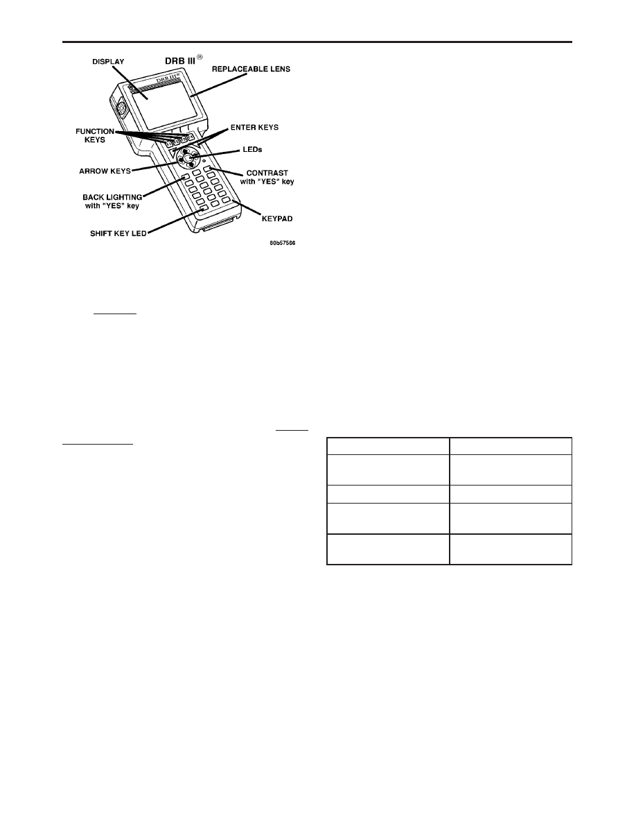
3.6.1
DRBIII
T DOES NOT POWER UP
If the LED’s do not light or no sound is emitted at
start up, check for loose cable connections or a bad
cable. Check the vehicle battery voltage (data link
connector cavity 16). A minimum of 11 volts is
required to adequately power the DRBIII
t.
If all connections are proper and the vehicle
battery is fully charged, an inoperative DRBIII
t
may be the result of faulty cable or vehicle wiring.
3.6.2
DISPLAY IS NOT VISIBLE
Low temperatures will affect the visibility of the
display. Adjust the contrast to compensate for this
condition.
4.0
DISCLAIMERS, SAFETY,
WARNINGS
4.1
DISCLAIMERS
All information, illustrations, and specifications
contained in this manual are based on the latest
4
GENERAL INFORMATION
information available at the time of publication.
The right is reserved to make changes at any time
without notice.
4.2
SAFETY
4.2.1
TECHNICIAN SAFETY INFORMATION
WARNING: ENGINES PRODUCE CARBON
MONOXIDE THAT IS ODORLESS, CAUSES
SLOWER REACTION TIME, AND CAN LEAD
TO SERIOUS INJURY. WHEN THE ENGINE IS
OPERATING, KEEP SERVICE AREAS WELL
VENTILATED OR ATTACH THE VEHICLE
EXHAUST SYSTEM TO THE SHOP EXHAUST
REMOVAL SYSTEM.
Set the parking brake and block the wheels before
testing or repairing the vehicle. It is especially
important to block the wheels on front-wheel drive
vehicles; the parking brake does not hold the drive
wheels.
When servicing a vehicle, always wear eye pro-
tection, and remove any metal jewelry such as
rings, watchbands or bracelets that might make an
inadvertent electrical contact.
When diagnosing a chassis problem, it is impor-
tant to follow approved procedures where applica-
ble. These procedures can be found in the service
manual. Following these procedures is very impor-
tant to the safety of individuals performing diag-
nostic tests.
4.2.2
VEHICLE PREPARATION FOR
TESTING
Make sure the vehicle being tested has a fully
charged battery. If is does not, false diagnostic codes
or error messages may occur.
4.2.3
SERVICING SUB-ASSEMBLIES
Some components of the chassis system are in-
tended to be serviced as an assembly only. Attempt-
ing to remove or repair certain system sub-
components may result in personal injury and/or
improper system operation. Only those components
with approved repair and installation procedures in
the service manual should be serviced.
4.2.4
DRBIII
T SAFETY INFORMATION
WARNING: EXCEEDING THE LIMITS OF THE
DRBIII
T
MULTIMETER IS DANGEROUS. IT
CAN
EXPOSE
YOU
TO
SERIOUS
OR
POSSIBLY
FATAL
INJURY.
CAREFULLY
READ AND UNDERSTAND THE CAUTIONS
AND THE SPECIFICATION LIMITS.
•
Follow the vehicle manufacturer’s service speci-
fications at all times.
•
Do not use the DRBIII
t if it has been damaged.
•
Do not use the test leads if the insulation is
damaged or if metal is exposed.
•
To avoid electrical shock, do not touch the test
leads, tips, or the circuit being tested.
•
Choose the proper range and functions for the
measurement. Do not try voltage or current mea-
surements that may exceed the rated capacity.
•
Do not exceed the limits shown in the table below:
FUNCTION
INPUT LIMIT
Volts
0 - 500 peak volts AC
0 - 500 volts DC
Ohms (resistance)*
0 -1.12 megohms
Frequency Measured
Frequency Generated
0 - 10 kHz
Temperature
-58 - 1100°F
-50 - 600°C
* Ohms cannot be measured if voltage is present.
Ohms can be measured only in a non-powered
circuit.
•
Voltage between any terminal and ground must
not exceed 500v DC or 500v peak AC.
•
Use caution when measuring voltage above 25v
DC or 25v AC.
•
Use the low current shunt to measure circuits up
to 10A. Use the high current clamp to measure
circuits exceeding 10A.
•
When testing for the presence of voltage or cur-
rent, make sure the meter is functioning cor-
rectly. Take a reading of a known voltage or
current before accepting a zero reading.
5
GENERAL INFORMATION

•
When measuring current, connect the meter in
series with the load.
•
Disconnect the live test lead before disconnecting
the common test lead.
•
When using the meter function, keep the
DRBIII
t away from spark plug or coil wires to
avoid measuring error from outside interference.
4.3
WARNINGS
4.3.1
VEHICLE DAMAGE WARNINGS
Before disconnecting any control module, make
sure the ignition is ‘‘off ’’. Failure to do so could
damage the module.
When testing voltage or continuity at any control
module, use the terminal side (not the wire end) of
the connector. Do not probe a wire through the
insulation, this will damage it and eventually cause
it to fail because of corrosion.
Be careful when performing electrical tests so as
to prevent accidental shorting of terminals. Such
mistakes can damage fuses or components. Also, a
second code could be set, making diagnosis of the
original problem more difficult.
4.3.2
ROAD TESTING A COMPLAINT
VEHICLE
Some complaints will require a test drive as part
of the repair verification procedure. The purpose of
the test drive is to try to duplicate the diagnostic
code or symptom condition.
WARNING:
BEFORE
ROAD
TESTING
A
VEHICLE,
BE
SURE
THAT
ALL
COMPONENTS
ARE
REASSEMBLED.
DURING THE TEST DRIVE, DO NOT TRY TO
READ THE DRB SCREEN WHILE IN MOTION.
DO NOT HANG THE DRBIII
T
FROM THE
REAR
VIEW
MIRROR
OR
OPERATE
IT
YOURSELF.
HAVE
AN
ASSISTANT
AVAILABLE TO OPERATE THE DRBIII
T
.
4.4
DIAGNOSIS
1. Your diagnostic test procedure must begin with a
thorough visual inspection of the system in ques-
tion for damaged components or disconnected
connectors. For ABS the brake lamps must be
operational prior to continuing.
2. Connect the DRBIII
t to the data link connector,
which is located under the dash to the left of the
steering column. If the DRBIII
t does not power
up, check the power and ground supplies to the
connector.
3. Turn the ignition on. Select the system in ques-
tion. If the DRBIII
t displays “No Response”
condition you must diagnose that first.
4. Read and record all diagnostic trouble codes. For
ABS if the “Valve Power Feed Circuit” diagnostic
trouble code is present, it must be repaired prior
to addressing any other DTC’s. If any additional
DTC’s are present, proceed to the appropriate
test by locating the matching test in the Table of
Contents and begin to diagnose the symptom.
5. For ABS if there are no diagnostic trouble codes
present, identify the customer complaint. Select
“Inputs/Outputs” and read the brake switch in-
put as you press and release the brake pedal. If
the display does not match the state of the pedal,
perform the proper test by locating the matching
test in the Table of Contents and begin to diag-
nose the symptom. If a problem exists with the
yellow “ABS” warning indicator or the red
“Brake” indicator exists, refer to the proper tests
by locating the matching test in the Table of
Contents and begin to diagnose the symptom.
Read the traction control switch input as you
press and release the switch. If the display does
not match the state of the indicator perform the
proper test by locating the matching test in the
Table of Contents and begin to diagnose the
symptom.
6. If no other problems are found, it will be neces-
sary to road test the vehicle. Perform several
antilock stops from above 50 Km/h (30 mph) and
then repeat step 4. If any diagnostic trouble
codes are present, proceed to the appropriate
test.
7. The following conditions should be considered
“NORMAL” operation, and no repairs should be
attempted to correct them.
– Brake pedal feedback during an ABS stop
(clicking, vibrating).
– Clicking, groaning or buzzing at 25 Km/h (15
mph) or 40 Km/h (24 mph) (drive off self test).
– Groaning noise during an ABS stop.
– Slight brake pedal drop and pop noise when
ignition is initially turned on.
– Brake pedal ratcheting down at the end of an
ABS stop.
8. If the complaint is ABS “cycling” at the end of a
stop at low speeds, it may be caused by a
marginal wheel speed sensor signal. The sensor
air gap, tone wheel condition, and/or brakes
hanging up are possible causes of this condition.
9. After a road test in which no problems were
found, refer to any Technical Service Bulletins
that may apply.
6
GENERAL INFORMATION

5.0
REQUIRED TOOLS AND
EQUIPMENT
DRBIII
t (diagnostic read-out box)
jumper wires
ohmmeter
voltmeter
test light
6.0
GLOSSARY OF TERMS
ABS
antilock brake system
CAB
controller antilock brake
DC
direct current
DLC
data link connector
DRB
diagnostic read-out box
DTC
diagnostic test code
EVBP
electronic variable brake proportion-
ing
HCU
hydraulic control unit
ICU
integrated control unit
IPM
integrated power module
JBLK
junction block
PCI
programmable communication inter-
face
P/M
pump motor
WSS
wheel speed sensor
7
GENERAL INFORMATION

NOTES
8

7.0
DIAGNOSTIC INFORMATION AND
PROCEDURES
9

Symptom:
INTERNAL CONTROLLER ERROR
When Monitored and Set Condition:
INTERNAL CONTROLLER ERROR
When Monitored:
Any time that the module is awake.
Set Condition:
When the APM detects an internal fault, the DTC is set.
POSSIBLE CAUSES
INTERMITTENT DTC
APM - INTERNAL FAULT
TEST
ACTION
APPLICABILITY
1
Set the memory positions according to the owner’s preferences.
Recall the memory positions.
With the DRBIII
t, erase DTC’s.
With the DRBIII
t, read DTC’s.
Does the DRBIII
t display INTERNAL CONTROLLER ERROR DTC active?
All
Yes
→ Replace and program the Adjustable Pedals Module in accordance
with the Service Information.
Perform ADJUSTABLE PEDALS VERIFICATION TEST - VER
1.
No
→ Go To 2
2
Turn the ignition off.
Visually inspect the related wiring harness. Look for any chafed, pierced, pinched, or
partially broken wires.
Visually inspect the related wire harness connectors. Look for broken, bent, pushed
out, or corroded terminals.
Refer to any Hotline letters or Technical Service Bulletins that may apply.
Were any problems found?
All
Yes
→ Repair as necessary.
Perform ADJUSTABLE PEDALS VERIFICATION TEST - VER
1.
No
→ Test Complete.
10
ADJUSTABLE PEDALS

Symptom:
PEDAL SENSOR OPEN/SHORTED TO GROUND
When Monitored and Set Condition:
PEDAL SENSOR OPEN/SHORTED TO GROUND
When Monitored:
Continuously.
Set Condition:
When the Adjustable Pedals Module detects a ground condition on the
Adjustable Pedal Sensor Signal circuit.
POSSIBLE CAUSES
INTERMITTENT DTC
ADJUSTABLE PEDALS SENSOR FEED CIRCUIT OPEN
ADJUSTABLE PEDALS SENSOR RETURN CIRCUIT OPEN
ADJUSTABLE PEDALS SENSOR SIGNAL CIRCUIT OPEN
ADJUSTABLE PEDALS SENSOR FAULT
APM - INTERNAL FAULT
TEST
ACTION
APPLICABILITY
1
With the DRBIII
t, erase DTC’s.
With the DRBIII
t, read DTC’s.
Does the DRBIII
t display PEDAL SENSOR OPEN/SHORTED TO GROUND DTC
active?
All
Yes
→ Go To 2
No
→ Go To 8
2
Turn the ignition off.
Ensure the Adjustable Pedals Sensor is fully seated and locked.
Turn the ignition on.
With the DRBIII
t, read the active DTC’s.
Does the DRBIII
t display PEDAL SENSOR OPEN/SHORTED TO GROUND DTC
active?
All
Yes
→ Go To 3
No
→ Go To 8
3
Turn the ignition off.
Disconnect the Adjustable Pedals Sensor harness connector.
Turn the ignition on.
Measure the voltage between the Adjustable Pedals Sensor Feed circuit and the
Adjustable Pedals Sensor Return circuit.
Is the voltage between 4 and 5.2 volts?
All
Yes
→ Go To 4
No
→ Go To 6
11
ADJUSTABLE PEDALS

TEST
ACTION
APPLICABILITY
4
Turn the ignition off.
Disconnect the Adjustable Pedals Sensor harness connector.
Disconnect the Adjustable Pedals Module harness connector.
Measure the resistance of the Adjustable Pedals Sensor Signal circuit between the
Adjustable Pedals Sensor connector and the Adjustable Pedals Module connector.
Is the resistance below 1.0 ohm?
All
Yes
→ Go To 5
No
→ Repair the Adjustable Pedals Sensor Signal circuit for an open.
Perform ADJUSTABLE PEDALS VERIFICATION TEST - VER
1.
5
Turn the ignition off.
Disconnect the Adjustable Pedals Sensor harness connector.
Measure the resistance between the Adjustable Pedals Sensor Signal circuit and the
Adjustable Pedals Sensor Return circuit at the Adjustable Pedals Sensor harness
connector.
Is the resistance below 100.0 ohms?
All
Yes
→ Replace and program the Adjustable Pedals Module in accordance
with the Service Information..
Perform ADJUSTABLE PEDALS VERIFICATION TEST - VER
1.
No
→ Replace the Adjustable Pedals Sensor in accordance with the
Service Information.
Perform ADJUSTABLE PEDALS VERIFICATION TEST - VER
1.
6
Turn the ignition off.
Disconnect the Adjustable Pedals Sensor harness connector.
Disconnect the Adjustable Pedals Module harness connector.
Measure the resistance of the Adjustable Pedals Sensor Feed circuit between the
Adjustable Pedals Sensor connector and the Adjustable Pedals Module connector.
Is the resistance below 1.0 ohm?
All
Yes
→ Go To 7
No
→ Repair the Adjustable Pedals Sensor Feed circuit for an open.
Perform ADJUSTABLE PEDALS VERIFICATION TEST - VER
1.
7
Turn the ignition off.
Disconnect the Adjustable Pedals Sensor harness connector.
Disconnect the Adjustable Pedals Module harness connector.
Measure the resistance of the Adjustable Pedals Sensor Return circuit between the
Adjustable Pedals Sensor connector and the Adjustable Pedals Module connector.
Is the resistance below 1.0 ohm?
All
Yes
→ Replace and program the Adjustable Pedals Module in accordance
with the Service Information..
Perform ADJUSTABLE PEDALS VERIFICATION TEST - VER
1.
No
→ Repair the Adjustable Pedals Sensor Return circuit for an open.
Perform ADJUSTABLE PEDALS VERIFICATION TEST - VER
1.
12
ADJUSTABLE PEDALS
PEDAL SENSOR OPEN/SHORTED TO GROUND —
Continued

TEST
ACTION
APPLICABILITY
8
Turn the ignition off.
Visually inspect the related wiring harness. Look for any chafed, pierced, pinched, or
partially broken wires.
Visually inspect the related wire harness connectors. Look for broken, bent, pushed
out, or corroded terminals.
Refer to any Hotline letters or Technical Service Bulletins that may apply.
Were any problems found?
All
Yes
→ Repair as necessary.
Perform ADJUSTABLE PEDALS VERIFICATION TEST - VER
1.
No
→ Test Complete.
13
ADJUSTABLE PEDALS
PEDAL SENSOR OPEN/SHORTED TO GROUND —
Continued

Symptom:
PEDAL SENSOR SHORTED TO BATTERY
When Monitored and Set Condition:
PEDAL SENSOR SHORTED TO BATTERY
When Monitored:
Continuously.
Set Condition:
When the Adjustable Pedals Module detects the voltage on the Adjustable
Pedal Sensor Signal circuit is too high.
POSSIBLE CAUSES
INTERMITTENT DTC
ADJUSTABLE PEDALS SENSOR FAULT
ADJUSTABLE PEDALS SENSOR SIGNAL CIRCUIT SHORTED TO BATTERY
ADJUSTABLE PEDALS SENSOR RETURN CIRCUIT OPEN
APM - INTERNAL FAULT
TEST
ACTION
APPLICABILITY
1
With the DRBIII
t, erase DTC’s.
With the DRBIII
t, read DTC’s.
Does the DRBIII
t display PEDAL SENSOR SHORTED TO BATTERY DTC active?
All
Yes
→ Go To 2
No
→ Go To 6
2
Turn the ignition off.
Ensure the Adjustable Pedals Sensor is fully seated and locked.
Turn the ignition on.
With the DRBIII
t, read the active DTC’s.
Does the DRBIII
t display PEDAL SENSOR SHORTED TO BATTERY DTC active?
All
Yes
→ Go To 3
No
→ Go To 6
3
Disconnect the Adjustable Pedals Sensor harness connector.
Turn the ignition on.
With the DRBIII
t, read the active DTC’s.
Does the DRBIII
t display PEDAL SENSOR SHORTED TO BATTERY active?
All
Yes
→ Go To 4
No
→ Replace the Adjustable Pedals Sensor in accordance with the
Service Information.
Perform ADJUSTABLE PEDALS VERIFICATION TEST - VER
1.
14
ADJUSTABLE PEDALS

TEST
ACTION
APPLICABILITY
4
Turn the ignition off.
Disconnect the Adjustable Pedals Sensor harness connector.
Disconnect the Adjustable Pedals Module harness connector.
Note: Check connector - Clean/repair as necessary.
Turn the ignition on.
Measure the voltage of the Adjustable Pedals Sensor Signal circuit.
Is there any voltage present?
All
Yes
→ Repair the Adjustable Pedals Sensor Signal circuit for a short to
voltage.
Perform ADJUSTABLE PEDALS VERIFICATION TEST - VER
1.
No
→ Go To 5
5
Turn the ignition off.
Disconnect the Adjustable Pedals Sensor harness connector.
Disconnect the Adjustable Pedals Module harness connector.
Note: Check connector - Clean/repair as necessary.
Measure the resistance of the Adjustable Pedals Sensor Return circuit between the
Adjustable Pedals Sensor connector and the APM connector.
Is the resistance below 1 ohm?
All
Yes
→ Replace and program the Adjustable Pedals Module in accordance
with the Service Information..
Perform ADJUSTABLE PEDALS VERIFICATION TEST - VER
1.
No
→ Repair the Adjustable Pedals Sensor Return circuit for an open.
Perform ADJUSTABLE PEDALS VERIFICATION TEST - VER
1.
6
Turn the ignition off.
Visually inspect the related wiring harness. Look for any chafed, pierced, pinched, or
partially broken wires.
Visually inspect the related wire harness connectors. Look for broken, bent, pushed
out, or corroded terminals.
Move the pedals all the way forward and rearward to see if the DTC is related to
position.
Refer to any Hotline letters or Technical Service Bulletins that may apply.
Were any problems found?
All
Yes
→ Repair as necessary.
Perform ADJUSTABLE PEDALS VERIFICATION TEST - VER
1.
No
→ Test Complete.
15
ADJUSTABLE PEDALS
PEDAL SENSOR SHORTED TO BATTERY —
Continued

Symptom:
PEDAL SW STUCK FORWARD
When Monitored and Set Condition:
PEDAL SW STUCK FORWARD
When Monitored:
Continuously.
Set Condition:
When the Adjustable Pedals Module detects battery voltage on the
Adjustable Pedals Switch Forward circuit for more than 20 seconds.
POSSIBLE CAUSES
INTERMITTENT DTC
ADJUSTABLE PEDALS SWITCH FAULT
ADJUSTABLE PEDALS SWITCH FORWARD CIRCUIT SHORTED TO BATTERY
APM - INTERNAL FAULT
TEST
ACTION
APPLICABILITY
1
With the DRBIII
t, erase DTC’s.
Turn the ignition on.
Wait 30 seconds.
With the DRBIII
t, read DTC’s.
Does the DRBIII
t display PEDAL SW STUCK FORWARD DTC active?
All
Yes
→ Go To 2
No
→ Go To 4
2
Turn the ignition off.
Disconnect the Adjustable Pedals Switch connector.
Turn the ignition on.
With the DRBIII
t, read DTC’s.
Does the DRBIII
t display PEDAL SW STUCK FORWARD DTC active?
All
Yes
→ Go To 3
No
→ Replace the Adjustable Pedals Switch in accordance with the
Service Information.
Perform ADJUSTABLE PEDALS VERIFICATION TEST - VER
1.
16
ADJUSTABLE PEDALS

TEST
ACTION
APPLICABILITY
3
Turn the ignition off.
Disconnect the Adjustable Pedals Module harness connector.
Disconnect the Adjustable Pedals Switch connector.
Turn the ignition ON.
Measure the voltage of the Adjustable Pedals Switch Forward circuit.
Is there any voltage present?
All
Yes
→ Repair the Adjustable Pedals Switch Forward circuit for a short to
voltage.
Perform ADJUSTABLE PEDALS VERIFICATION TEST - VER
1.
No
→ Replace and program the Adjustable Pedals Module in accordance
with the Service Information.
Perform ADJUSTABLE PEDALS VERIFICATION TEST - VER
1.
4
Turn the ignition off.
Visually inspect the related wiring harness. Look for any chafed, pierced, pinched, or
partially broken wires.
Visually inspect the related wire harness connectors. Look for broken, bent, pushed
out, or corroded terminals.
Refer to any Hotline letters or Technical Service Bulletins that may apply.
Were any problems found?
All
Yes
→ Repair as necessary.
Perform ADJUSTABLE PEDALS VERIFICATION TEST - VER
1.
No
→ Test Complete.
17
ADJUSTABLE PEDALS
PEDAL SW STUCK FORWARD —
Continued

Symptom:
PEDAL SW STUCK REARWARD
When Monitored and Set Condition:
PEDAL SW STUCK REARWARD
When Monitored:
Continuously.
Set Condition:
When the Adjustable Pedals Module detects battery voltage on the
Adjustable Pedals Switch Rearward circuit for more than 20 seconds.
POSSIBLE CAUSES
INTERMITTENT DTC
ADJUSTABLE PEDALS SWITCH FAULT
ADJUSTABLE PEDALS SWITCH REARWARD CIRCUIT SHORTED TO BATTERY
APM - INTERNAL FAULT
TEST
ACTION
APPLICABILITY
1
With the DRBIII
t, erase DTC’s.
Turn the ignition on.
Wait 30 seconds.
With the DRBIII
t, read DTC’s.
Does the DRBIII
t display PEDAL SW STUCK REARWARD DTC active?
All
Yes
→ Go To 2
No
→ Go To 4
2
Turn the ignition off.
Disconnect the Adjustable Pedals Switch connector.
Turn the ignition on.
With the DRBIII
t, read DTC’s.
Does the DRBIII
t display PEDAL SW STUCK REARWARD DTC active?
All
Yes
→ Go To 3
No
→ Replace the Adjustable Pedals Switch in accordance with the
Service Information.
Perform ADJUSTABLE PEDALS VERIFICATION TEST - VER
1.
18
ADJUSTABLE PEDALS

TEST
ACTION
APPLICABILITY
3
Turn the ignition off.
Disconnect the Adjustable Pedals Module harness connector.
Disconnect the Adjustable Pedals Switch connector.
Turn the ignition ON.
Measure the voltage of the Adjustable Pedals Switch Rearward circuit.
Is there any voltage present?
All
Yes
→ Repair the Adjustable Pedals Switch Rearward circuit for a short
to voltage.
Perform ADJUSTABLE PEDALS VERIFICATION TEST - VER
1.
No
→ Replace and program the Adjustable Pedals Module in accordance
with the Service Information.
Perform ADJUSTABLE PEDALS VERIFICATION TEST - VER
1.
4
Turn the ignition off.
Visually inspect the related wiring harness. Look for any chafed, pierced, pinched, or
partially broken wires.
Visually inspect the related wire harness connectors. Look for broken, bent, pushed
out, or corroded terminals.
Refer to any Hotline letters or Technical Service Bulletins that may apply.
Were any problems found?
All
Yes
→ Repair as necessary.
Perform ADJUSTABLE PEDALS VERIFICATION TEST - VER
1.
No
→ Test Complete.
19
ADJUSTABLE PEDALS
PEDAL SW STUCK REARWARD —
Continued

Symptom:
SYSTEM OVER VOLTAGE
When Monitored and Set Condition:
SYSTEM OVER VOLTAGE
When Monitored:
Any time that the module is awake.
Set Condition:
When the Adjustable Pedals Module detects 3 consecutive J1850 Bus
messages indicating vehicle voltage over 15.9 VDC.
POSSIBLE CAUSES
INTERMITTENT DTC
VEHICLE CHARGING SYSTEM FAULT
APM - INTERNAL FAULT
TEST
ACTION
APPLICABILITY
1
With the DRBIII
t, read the vehicle voltage status.
Does the DRBIII
t display a high voltage concern?
All
Yes
→ Refer to Charging information for the related symptom(s).
Perform ADJUSTABLE PEDALS VERIFICATION TEST - VER
1.
No
→ Go To 2
2
Turn the ignition off.
Turn the ignition on.
With the DRBIII
t, erase DTC’s.
Turn the ignition off.
Turn the ignition on.
Wait 10 seconds.
With the DRBIII
t, read DTC’s.
Does the DRBIII
t display SYSTEM OVER VOLTAGE DTC active?
All
Yes
→ Replace and program the Adjustable Pedals Module in accordance
with the Service Information.
Perform ADJUSTABLE PEDALS VERIFICATION TEST - VER
1.
No
→ Go To 3
20
ADJUSTABLE PEDALS

TEST
ACTION
APPLICABILITY
3
Turn the ignition off.
NOTE: Ensure the battery is fully charged.
Visually inspect the related wiring harness. Look for any chafed, pierced, pinched, or
partially broken wires.
Visually inspect the related wire harness connectors. Look for broken, bent, pushed
out, or corroded terminals.
Refer to any Hotline letters or Technical Service Bulletins that may apply.
Inspect the vehicle for aftermarket accessories that may exceed the Generator
System output.
Were any problems found?
All
Yes
→ Repair as necessary.
Perform ADJUSTABLE PEDALS VERIFICATION TEST - VER
1.
No
→ Test Complete.
21
ADJUSTABLE PEDALS
SYSTEM OVER VOLTAGE —
Continued

Symptom:
SYSTEM UNDER VOLTAGE
When Monitored and Set Condition:
SYSTEM UNDER VOLTAGE
When Monitored:
Any time that the module is awake.
Set Condition:
When the Adjustable Pedals Module detects 3 consecutive J1850 Vehicle
Battery Voltage messages indicating a battery voltage less than 9 VDC.
POSSIBLE CAUSES
INTERMITTENT DTC
VEHICLE CHARGING SYSTEM FAULT
ADJUSTABLE PEDALS MODULE HIGH RESISTANCE FUSE B+ CIRCUIT
APM - INTERNAL FAULT
TEST
ACTION
APPLICABILITY
1
With the DRBIII
t, read the vehicle voltage status.
Does the DRBIII
t display a low voltage concern?
All
Yes
→ Refer to Charging information for the related symptom(s).
Perform ADJUSTABLE PEDALS VERIFICATION TEST - VER
1.
No
→ Go To 2
2
Turn the ignition off.
Turn the ignition on.
With the DRBIII
t, erase DTC’s.
Turn the ignition off.
Turn the ignition on.
Wait 10 seconds.
With the DRBIII
t, read DTC’s.
Does the DRBIII
t display SYSTEM UNDER VOLTAGE DTC active?
All
Yes
→ Go To 3
No
→ Go To 4
22
ADJUSTABLE PEDALS

TEST
ACTION
APPLICABILITY
3
Turn the ignition off.
Disconnect the Adjustable Pedals Module harness connector.
Measure the voltage of the Adjustable Pedals Module Fused B+ circuit in the
Adjustable Pedals Module connector.
Is there battery voltage present?
All
Yes
→ Replace and program the Adjustable Pedals Module in accordance
with the Service Information.
Perform ADJUSTABLE PEDALS VERIFICATION TEST - VER
1.
No
→ Repair the Adjustable Pedals Module Fused B+ circuit for high
resistance.
Perform ADJUSTABLE PEDALS VERIFICATION TEST - VER
1.
4
Turn the ignition off.
NOTE: Ensure the battery is fully charged.
Visually inspect the related wiring harness. Look for any chafed, pierced, pinched, or
partially broken wires.
Visually inspect the related wire harness connectors. Look for broken, bent, pushed
out, or corroded terminals.
Refer to any Hotline letters or Technical Service Bulletins that may apply.
Inspect the vehicle for aftermarket accessories that may exceed the Generator
System output.
Were any problems found?
All
Yes
→ Repair as necessary.
Perform ADJUSTABLE PEDALS VERIFICATION TEST - VER
1.
No
→ Test Complete.
23
ADJUSTABLE PEDALS
SYSTEM UNDER VOLTAGE —
Continued

Symptom:
*CAN’T ADJUST PEDALS
POSSIBLE CAUSES
VEHICLE IN REVERSE OR CRUISE CONTROL ACTIVATED
BODY STYLE FAULT
IN-PLANT MODE ENABLED
ACTIVE DTC’S
ADJUSTABLE PEDALS SENSOR CONNECTOR NOT FULLY SEATED
ADJUSTABLE PEDALS MOTOR FAULT
ADJUSTABLE PEDALS MOTOR CIRCUITS OPEN
BUS COMMUNICATION FAULT
ADJUSTABLE PEDALS MODULE FUSED B+ CIRCUIT OPEN
ADJUSTABLE PEDALS MODULE GROUND CIRCUIT OPEN
IOD FUSE OPEN
ADJUSTABLE PEDALS SWITCH FUSED B+ CIRCUIT OPEN
ADJUSTABLE PEDALS SWITCH GROUND CIRCUIT OPEN
ADJUSTABLE PEDALS SWITCH FAULT
ADJUSTABLE PEDALS SWITCH REARWARD CIRCUIT OPEN
ADJUSTABLE PEDALS SWITCH FORWARD CIRCUIT OPEN
APM - INTERNAL FAULT
TEST
ACTION
APPLICABILITY
1
NOTE: Adjustable Pedals are disabled when the vehicle is in Reverse or
when the Speed Control is activated.
Check whether vehicle is(was) in Reverse and whether Speed Control is(was)
activated.
Is(was) the vehicle in Reverse or is(was) Speed Control activated?
All
Yes
→ Correct as necessary.
Perform ADJUSTABLE PEDALS VERIFICATION TEST - VER
1.
No
→ Go To 2
2
Turn the ignition on.
With the DRBIII
t, try to read Adjustable Pedals Module information.
Can the Adjustable Pedals Module be detected by the DRBIII
t?
All
Yes
→ Go To 3
No
→ Go To 19
24
ADJUSTABLE PEDALS

TEST
ACTION
APPLICABILITY
3
Turn the ignition on.
With the DRBIII
t, go to Module Display.
Does the DRBIII
t display RS BODY STYLE?
All
Yes
→ Go To 4
No
→ Replace the Adjustable Pedals Module in accordance with the
Service Information.
Perform ADJUSTABLE PEDALS VERIFICATION TEST - VER
1.
4
With the DRBIII
t, read the status of the In-Plant Mode.
Is the In-Plant Mode Enabled?
All
Yes
→ Disable the In-Plant mode.
Perform ADJUSTABLE PEDALS VERIFICATION TEST - VER
1.
No
→ Go To 5
5
Turn the ignition on.
With the DRBIII
t, erase DTC’s.
With the DRBIII
t, read DTC’s.
Does the DRBIII
t display any DTC’s active?
All
Yes
→ Refer to symptom list for problems related to the active DTC’s.
Perform ADJUSTABLE PEDALS VERIFICATION TEST - VER
1.
No
→ Go To 6
6
Turn the ignition on.
With the DRBIII
t in Inputs/Outputs, read the forward and rearward switches.
Actuate the Adjustable Pedals Switch in the forward and rearward positions.
Does the DRBIII
t display FORWARD/REARWARD SW CLOSED when switch is
activated?
All
Yes
→ Go To 7
No
→ Go To 11
7
Turn the ignition on.
With the DRBIII
t, actuate the pedal forward and pedal rearward.
Do the Adjustable Pedals move?
All
Yes
→ Replace and program the Adjustable Pedals Module in accordance
with the Service Information.
Perform ADJUSTABLE PEDALS VERIFICATION TEST - VER
1.
No
→ Go To 8
8
Turn the ignition off.
Ensure the Adjustable Pedals Sensor is fully seated and locked.
Inspect Adjustable Pedals Module connector and the Adjustable Pedals Motor
connector.
Are the connectors FULLY seated and properly plugged in?
All
Yes
→ Go To 9
No
→ Repair as necessary.
Perform ADJUSTABLE PEDALS VERIFICATION TEST - VER
1.
25
ADJUSTABLE PEDALS
*CAN’T ADJUST PEDALS —
Continued

TEST
ACTION
APPLICABILITY
9
Turn the ignition off.
Disconnect the Adjustable Pedals Motor harness connector.
Using a 12-volt test light, connect it between the Adjustable Pedals Motor Forward
and Adjustable Pedals Motor Rearward circuits at the Adjustable Pedals Motor
harness connector.
With the DRBIII
t, actuate the pedal forward and pedal rearward.
Does the test light illuminate brightly for both directions?
All
Yes
→ Replace the Adjustable Pedals Assembly in accordance with the
Service Information.
Perform ADJUSTABLE PEDALS VERIFICATION TEST - VER
1.
No
→ Go To 10
10
Turn the ignition on.
Using a 12-volt test light, back-probe between the Adjustable Pedals Motor Forward
and Adjustable Pedals Motor Rearward circuits at the Adjustable Pedals Module
harness connector.
With the DRBIII
t, actuate the pedal forward and pedal rearward.
Does the test light illuminate brightly for both directions?
All
Yes
→ Repair the Adjustable Pedals Motor Forward/Rearward circuit(s)
for an open.
Perform ADJUSTABLE PEDALS VERIFICATION TEST - VER
1.
No
→ Replace and program the Adjustable Pedals Module in accordance
with the Service Information.
Perform ADJUSTABLE PEDALS VERIFICATION TEST - VER
1.
11
Turn the ignition off.
Inspect for an open IOD fuse in the IPM.
Is the IOD fuse open?
All
Yes
→ Replace the fuse. If the fuse is open make sure to check for a short
to ground.
Perform ADJUSTABLE PEDALS VERIFICATION TEST - VER
1.
No
→ Go To 12
12
Turn the ignition off.
Disconnect the Adjustable Pedals Switch harness connector.
Measure the voltage between the Adjustable Pedals Switch Fused B+ and Ground
circuits (cavities 1 & 2).
Is there battery voltage present?
All
Yes
→ Go To 13
No
→ Go To 17
26
ADJUSTABLE PEDALS
*CAN’T ADJUST PEDALS —
Continued

TEST
ACTION
APPLICABILITY
13
Turn the ignition off.
Disconnect the Adjustable Pedals Switch harness connector.
Turn the ignition on.
With the DRBIII
t in Inputs/Outputs, monitor the FORWARD SW state.
Connect a jumper wire between the Adjustable Pedals Switch Fused B+ circuit and
the Adjustable Pedals Switch Forward circuit.
Does the DRBIII
t display FORWARD SW CLOSED?
All
Yes
→ Go To 14
No
→ Go To 16
14
Turn the ignition off.
Disconnect the Adjustable Pedals Switch harness connector.
Turn the ignition on.
With the DRBIII
t in Inputs/Outputs, monitor the REARWARD SW state.
Connect a jumper wire between the Adjustable Pedals Switch Fused B+ circuit and
the Adjustable Pedals Switch Rearward circuit.
Does the DRBIII
t display REARWARD SW CLOSED?
All
Yes
→ Replace the Adjustable Pedals Switch in accordance with the
Service Information.
Perform ADJUSTABLE PEDALS VERIFICATION TEST - VER
1.
No
→ Go To 15
15
Turn the ignition off.
Disconnect the Adjustable Pedals Switch harness connector.
Disconnect the Adjustable Pedals Module harness connector.
Measure the resistance of the Adjustable Pedals Switch Rearward circuit between
the Adjustable Pedals Switch connector and the Adjustable Pedals Module connector.
Is the resistance below 1.0 ohm?
All
Yes
→ Replace and program the Adjustable Pedals Module in accordance
with the Service Information.
Perform ADJUSTABLE PEDALS VERIFICATION TEST - VER
1.
No
→ Repair the Adjustable Pedals Switch Rearward circuit for an
open.
Perform ADJUSTABLE PEDALS VERIFICATION TEST - VER
1.
16
Turn the ignition off.
Disconnect the Adjustable Pedals Switch harness connector.
Disconnect the Adjustable Pedals Module harness connector.
Measure the resistance of the Adjustable Pedals Switch Forward circuit between the
Adjustable Pedals Switch connector and the Adjustable Pedals Module connector.
Is the resistance below 1.0 ohm?
All
Yes
→ Replace and program the Adjustable Pedals Module in accordance
with the Service Information.
Perform ADJUSTABLE PEDALS VERIFICATION TEST - VER
1.
No
→ Repair the Adjustable Pedals Switch Forward circuit for an open.
Perform ADJUSTABLE PEDALS VERIFICATION TEST - VER
1.
27
ADJUSTABLE PEDALS
*CAN’T ADJUST PEDALS —
Continued

TEST
ACTION
APPLICABILITY
17
Turn the ignition off.
Disconnect the Adjustable Pedals Switch harness connector.
Measure the voltage between Adjustable Pedals Switch Fused B+ circuit and vehicle
body ground.
Is there battery voltage present?
All
Yes
→ Go To 18
No
→ Repair the Adjustable Pedals Switch Fused B+ circuit for an open.
Perform ADJUSTABLE PEDALS VERIFICATION TEST - VER
1.
18
Turn the ignition off.
Disconnect the Adjustable Pedals Switch harness connector.
Measure the resistance between the Adjustable Pedals Switch Ground circuit and
vehicle body ground.
Is the resistance below 1.0 ohm?
All
Yes
→ Replace the Adjustable Pedals Switch in accordance with the
Service Information.
Perform ADJUSTABLE PEDALS VERIFICATION TEST - VER
1.
No
→ Repair the Adjustable Pedals Switch Ground circuit for an open.
Perform ADJUSTABLE PEDALS VERIFICATION TEST - VER
1.
19
Turn the ignition off.
Disconnect the Adjustable Pedals Module harness connector.
Measure the voltage between the Adjustable Pedals Module Fused B+ circuit and the
Ground circuit at the Adjustable Pedals Module harness connector.
Is there battery voltage present?
All
Yes
→ Refer to symptom *NO RESPONSE FROM ADJUSTABLE PED-
ALS ASSEMBLY in the BODY COMMUNICATION category.
Perform ADJUSTABLE PEDALS VERIFICATION TEST - VER
1.
No
→ Go To 20
20
Turn the ignition off.
Disconnect the Adjustable Pedals Module harness connector.
Measure the voltage between the Adjustable Pedals Module Fused B+ circuit and
vehicle body ground.
Is there battery voltage present?
All
Yes
→ Repair the Adjustable Pedals Module Ground circuit for an open.
Perform ADJUSTABLE PEDALS VERIFICATION TEST - VER
1.
No
→ Repair the Adjustable Pedals Module Fused B+ circuit for an
open.
Perform ADJUSTABLE PEDALS VERIFICATION TEST - VER
1.
28
ADJUSTABLE PEDALS
*CAN’T ADJUST PEDALS —
Continued

Symptom:
*CAN’T SET/RECALL MEMORY POSITIONS
POSSIBLE CAUSES
DTC OR IN-PLANT MODE ACTIVE
PEDALS OPERATION
BCM OPERATION FAULT
ADJUSTABLE PEDALS SENSOR
ADJUSTABLE PEDALS SENSOR VOLTAGE FAULT
BCM COMMUNICATION FAULT
APM - INTERNAL FAULT
TEST
ACTION
APPLICABILITY
1
With the DRBIII
t, erase DTC’s.
With the DRBIII
t, read the active DTC’s.
With the DRBIII
t, read the In-Plant state.
Any active DTC’s or is the In-Plant mode activated?
All
Yes
→ Disable the In-Plant mode or refer to symptom list for problems
related to the active DTC.
Perform ADJUSTABLE PEDALS VERIFICATION TEST - VER
1.
No
→ Go To 2
2
Attempt to adjust the pedals using the Adjustable Pedals Switch.
Do the pedals adjust?
All
Yes
→ Go To 3
No
→ Refer to *CAN’T ADJUST PEDALS information for the related
symptom(s).
Perform ADJUSTABLE PEDALS VERIFICATION TEST - VER
1.
3
Attempt to set and recall other memory functions in the vehicle.
Can other vehicle memory functions be set and recalled OK?
All
Yes
→ Go To 4
No
→ Check DTC’s in the BCM and refer to BODY information for the
related symptom(s).
Perform ADJUSTABLE PEDALS VERIFICATION TEST - VER
1.
29
ADJUSTABLE PEDALS

TEST
ACTION
APPLICABILITY
4
Turn the ignition off.
Turn the ignition on.
With the DRBIII
t in Sensors, read the pedal position voltage.
Monitor the pedal position voltage while adjusting pedals forward and rearward.
Is there any change of voltage?
All
Yes
→ Go To 5
No
→ Check for proper Adjustable Pedals Sensor installation and align-
ment. Check wiring and connectors. Repair as necessary.
Perform ADJUSTABLE PEDALS VERIFICATION TEST - VER
1.
5
Does the pedal position voltage increase when moving forward and decrease when
moving rearward?
All
Yes
→ Go To 6
No
→ Check Adjustable Pedals Sensor and APM pinouts. Repair as
necessary.
Perform ADJUSTABLE PEDALS VERIFICATION TEST - VER
1.
6
Can the DRBIII
t communicate with the BCM?
All
Yes
→ Replace the Adjustable Pedals Module in accordance with the
Service Information.
Perform ADJUSTABLE PEDALS VERIFICATION TEST - VER
1.
No
→ Refer to BODY information for the related symptom(s).
Perform ADJUSTABLE PEDALS VERIFICATION TEST - VER
1.
30
ADJUSTABLE PEDALS
*CAN’T SET/RECALL MEMORY POSITIONS —
Continued

Symptom:
BUS SYSTEM COMMUNICATION FAILURE
When Monitored and Set Condition:
BUS SYSTEM COMMUNICATION FAILURE
When Monitored:
Ignition ON, continuously.
Set Condition:
When the CAB does not receive a message from the instrument cluster for
10 seconds.
POSSIBLE CAUSES
INTERMITTENT CONDITION
ELECTRO-MECHANICAL INSTRUMENT CLUSTER DTC PRESENT
BUS CIRCUIT OPEN
CAB - INTERNAL FAILURE
TEST
ACTION
APPLICABILITY
1
Turn the ignition on.
With the DRBIII
t, read DTCs.
With the DRBIII
t, read Freeze Frame information.
With the DRBIII
t, erase DTCs.
Turn the ignition off.
Turn the ignition on.
With the DRBIII
t, read DTCs.
Does the DRBIII
t display BUS SYSTEM COMMUNICATION FAILURE?
All
Yes
→ Go To 2
No
→ Go To 4
2
Turn the ignition on.
With the DRBIII
t, read EMIC DTCs.
Does the DRBIII
t display NO ABS MESSAGE RECEIVED?
All
Yes
→ Refer to symptom NO ABS MESSAGE RECEIVED in the BODY/
INSTRUMENT CLUSTER category.
Perform ABS VERIFICATION TEST - VER 1.
No
→ Go To 3
31
BRAKES (CAB)

TEST
ACTION
APPLICABILITY
3
Turn the ignition off.
Disconnect the negative (-) battery cable.
Disconnect the CAB harness connector.
NOTE: check connector - Clean/repair as necessary.
Measure the resistance of the Bus circuit between the CAB connector and the Data
Link Connector (DLC).
Is the resistance below 5.0 ohms?
All
Yes
→ Replace the Controller Antilock Brake in accordance with the
Service Information.
Perform ABS VERIFICATION TEST - VER 1.
No
→ Repair the Bus circuit for an open.
Perform ABS VERIFICATION TEST - VER 1.
4
Turn the ignition off.
Visually inspect the related wiring harness. Look for any chafed, pierced, pinched, or
partially broken wires.
Visually inspect the related wire harness connectors. Look for broken, bent, pushed
out, or corroded terminals.
Were any problems found?
All
Yes
→ Repair as necessary.
Perform ABS VERIFICATION TEST - VER 1.
No
→ Test Complete.
32
BRAKES (CAB)
BUS SYSTEM COMMUNICATION FAILURE —
Continued

Symptom:
CAB INTERNAL FAILURE
When Monitored and Set Condition:
CAB INTERNAL FAILURE
When Monitored:
Ignition on. The CAB monitors its internal microprocessors for correct
operation.
Set Condition:
If the CAB detects an internal fault, the DTC is set.
POSSIBLE CAUSES
INTERMITTENT DTC
DAMAGED CAB/CAB HARNESS CONNECTOR
CAB - GROUND CIRCUIT OPEN
ABS VALVE FUSED B(+) CIRCUIT OPEN
ABS PUMP FUSED B(+) CIRCUIT OPEN
CAB - INTERNAL FAULT
TEST
ACTION
APPLICABILITY
1
Turn the ignition on.
With the DRBIII
t, read DTCs.
With the DRBIII
t, erase DTCs.
Turn the ignition off.
Turn the ignition on.
With the DRBIII
t, read DTCs.
Does the DRBIII
t display CAB INTERNAL FAILURE?
All
Yes
→ Go To 2
No
→ Go To 6
2
Turn the ignition off.
Disconnect the CAB harness connector.
Inspect the CAB/CAB harness connector for damage.
Is there any broken, bent, pushed out, corroded or spread terminals?
All
Yes
→ Repair as necessary.
Perform ABS VERIFICATION TEST - VER 1.
No
→ Go To 3
3
Turn the ignition off.
Disconnect the CAB harness connector.
Using a 12-volt test light connected to 12-volts, probe the CAB harness connector
ground circuits.
Did the test light illuminate?
All
Yes
→ Go To 4
No
→ Repair the CAB Ground circuit for an open.
Perform ABS VERIFICATION TEST - VER 1.
33
BRAKES (CAB)

TEST
ACTION
APPLICABILITY
4
Turn the ignition off.
Disconnect the CAB harness connector.
Using a 12-volt test light connected to ground, probe the ABS Valve Fused B(+) circuit
at the CAB harness connector.
Did the test light illuminate?
All
Yes
→ Go To 5
No
→ Repair the ABS Valve Fused B(+) circuit for an open.
Perform ABS VERIFICATION TEST - VER 1.
5
Turn the ignition off.
Disconnect the CAB harness connector.
Using a 12-volt test light connected to ground, probe the ABS Pump Fused B(+)
circuit at the CAB harness connector.
Did the test light illuminate?
All
Yes
→ Replace the Controller Antilock Brake in accordance with the
Service Information.
Perform ABS VERIFICATION TEST - VER 1.
No
→ Repair the ABS Pump Fused B(+) circuit for an open.
Perform ABS VERIFICATION TEST - VER 1.
6
Turn the ignition off.
Visually inspect the related wiring harness. Look for any chafed, pierced, pinched, or
partially broken wires.
Visually inspect the related wire harness connectors. Look for broken, bent, pushed
out, or corroded terminals.
Refer to any Hotline letters or Technical Service Bulletins that may apply.
Were any problems found?
All
Yes
→ Repair as necessary.
Perform ABS VERIFICATION TEST - VER 1.
No
→ Test Complete.
34
BRAKES (CAB)
CAB INTERNAL FAILURE —
Continued

Symptom:
CLUSTER LAMP FAILURE
When Monitored and Set Condition:
CLUSTER LAMP FAILURE
When Monitored:
Key ON. After Key-ON bulb check.
Set Condition:
When the instrument cluster informs the CAB that the cluster cannot
turn on the ABS Lamp.
POSSIBLE CAUSES
INSTRUMENT CLUSTER OR ABS DTC PRESENT
INSTRUMENT CLUSTER
CAB - NO DTC SIGNAL TO THE INSTRUMENT CLUSTER
CAB - NO KEY-ON BULB CHECK SIGNAL
CAB - PERMANENT FAULT SIGNAL
TEST
ACTION
APPLICABILITY
1
Turn the ignition on.
With the DRBIII
t, read DTCs.
Are there any Instrument Cluster or ABS DTCs present?
All
Yes
→ Refer to the appropriate category for the related symptom(s).
Perform ABS VERIFICATION TEST - VER 1.
No
→ Go To 2
2
Turn the ignition off.
Perform the Key-on Bulb Check.
Does the ABS Warning Indicator light and then go out after a few seconds?
All
Yes
→ Go To 3
No. Light remains after bulb check.
Replace the Controller Antilock Brake in accordance with the
Service Information.
Perform ABS VERIFICATION TEST - VER 1.
No. Indicator never comes on.
35
BRAKES (CAB)

TEST
ACTION
APPLICABILITY
3
NOTE: The DRBIII
t communication with the CAB must be operational for
the result of this test to be valid.
Turn the ignition off.
Remove ABS Valve fuse.
Perform the Key-on Bulb Check.
Does the ABS Indicator remain on after the bulb check?
All
Yes
→ Test Complete.
No
→ Replace the Controller Antilock Brake in accordance with the
Service Information.
Perform ABS VERIFICATION TEST - VER 1.
4
NOTE: The following steps will initiate the Instrument Cluster self test.
Turn the ignition off.
Press and hold the odometer reset button.
Turn the ignition to RUN.
Observe the Instrument Cluster indicators.
Release the odometer reset button.
Did the ABS Indicator illuminate during the Instrument Cluster self test?
All
Yes
→ Replace the Controller Antilock Brake in accordance with the
Service Information.
Perform ABS VERIFICATION TEST - VER 1.
No
→ Replace the Instrument Cluster in accordance with the Service
Information.
Perform ABS VERIFICATION TEST - VER 1.
36
BRAKES (CAB)
CLUSTER LAMP FAILURE —
Continued

Symptom:
INCORRECT TONE WHEEL FAILURE
When Monitored and Set Condition:
INCORRECT TONE WHEEL FAILURE
When Monitored:
Ignition ON. Vehicle speed above 40 km/h (25 mph) for 2 minutes.
Set Condition:
When the CAB detects an unexpected wheel speed condition caused by a
tire size that does not meet vehicle specification.
37
BRAKES (CAB)

Symptom List:
LEFT FRONT SENSOR CIRCUIT FAILURE
LEFT REAR SENSOR CIRCUIT FAILURE
RIGHT FRONT SENSOR CIRCUIT FAILURE
RIGHT REAR SENSOR CIRCUIT FAILURE
Test Note:
All symptoms listed above are diagnosed using the same tests.
The title for the tests will be LEFT FRONT SENSOR CIRCUIT
FAILURE.
When Monitored and Set Condition:
LEFT FRONT SENSOR CIRCUIT FAILURE
When Monitored:
Ignition on. The CAB monitors the wheel speed circuit continuously.
Set Condition:
If the CAB detects an open or shorted wheel speed sensor circuit, the
Diagnostic Trouble Code (DTC) will set.
LEFT REAR SENSOR CIRCUIT FAILURE
When Monitored:
Ignition on. The CAB monitors the wheel speed circuit continuously.
Set Condition:
If the CAB detects an open or shorted wheel speed sensor circuit, the
Diagnostic Trouble Code (DTC) will set.
RIGHT FRONT SENSOR CIRCUIT FAILURE
When Monitored:
Ignition on. The CAB monitors the wheel speed circuit continuously.
Set Condition:
If the CAB detects an open or shorted wheel speed sensor circuit, the
Diagnostic Trouble Code (DTC) will set.
RIGHT REAR SENSOR CIRCUIT FAILURE
When Monitored:
Ignition on. The CAB monitors the wheel speed circuit continuously.
Set Condition:
If the CAB detects an open or shorted wheel speed sensor circuit, the
Diagnostic Trouble Code (DTC) will set.
POSSIBLE CAUSES
INTERMITTENT CONDITION
WHEEL SPEED SENSOR OR CONNECTOR DAMAGE
WHEEL SPEED SENSOR SIGNAL CIRCUIT FAULT
WHEEL SPEED SENSOR 12 VOLT SUPPLY CIRCUIT SHORT TO GROUND
WHEEL SPEED SENSOR 12 VOLT SUPPLY CIRCUIT OPEN
WHEEL SPEED SENSOR SIGNAL CIRCUIT SHORT TO GROUND
WHEEL SPEED SENSOR SIGNAL CIRCUIT OPEN
38
BRAKES (CAB)

POSSIBLE CAUSES
CAB - 12 VOLT SUPPLY CIRCUIT FAULT
CAB - SIGNAL CIRCUIT FAULT
WHEEL SPEED SENSOR 12 VOLT SUPPLY SHORT TO GROUND
WHEEL SPEED SENSOR SIGNAL CIRCUIT INOPERATIVE
TEST
ACTION
APPLICABILITY
1
Turn the ignition on.
With the DRBIII
t, read DTCs.
With the DRBIII
t, read the Freeze Frame information.
With the DRBIII
t, erase DTCs.
Turn the ignition off.
Turn the ignition on.
With the DRBIII
t, read DTCs.
NOTE: The CAB must sense all four wheels at 25km/h (15 mph) before it will
extinguish the ABS indicators.
Does the DRBIII
t display SENSOR CIRCUIT FAILURE?
All
Yes
→ Go To 2
No
→ Go To 13
2
Turn the ignition off.
Inspect the CAB connector, affected Wheel Speed Sensor, and affected Wheel Speed
Sensor connector.
Is the affected Wheel Speed Sensor or any of the connectors damaged?
All
Yes
→ Repair as necessary.
Perform ABS VERIFICATION TEST - VER 1.
No
→ Go To 3
3
Turn the ignition off.
Disconnect the affected Wheel Speed Sensor connector.
Note: Check connector - Clean/repair as necessary.
Turn the ignition on.
Measure the voltage between affected Wheel Speed Sensor 12 Volt Supply circuit and
ground.
Is the voltage above 10 volts?
All
Yes
→ Go To 6
No
→ Go To 4
4
Turn the ignition off.
Disconnect the CAB harness connector.
Disconnect the affected Wheel Speed Sensor connector.
Using a 12-volt test light connected to 12-volts, probe the affected Wheel Speed
Sensor 12 Volt Supply circuit.
Does the test light illuminate?
All
Yes
→ Repair the affected Wheel Speed Sensor 12 Volt Supply circuit for
a short to ground.
Perform ABS VERIFICATION TEST - VER 1.
No
→ Go To 5
39
BRAKES (CAB)
LEFT FRONT SENSOR CIRCUIT FAILURE —
Continued

TEST
ACTION
APPLICABILITY
5
Turn the ignition off.
Disconnect the CAB harness connector.
Disconnect the affected Wheel Speed Sensor connector.
Connect a jumper wire between affected Wheel Speed Sensor 12 Volt Supply circuit
and ground.
Using a 12-volt test light connected to 12-volts, probe the affected Wheel Speed
Sensor 12 Volt Supply circuit.
Does the test light illuminate?
All
Yes
→ Go To 6
No
→ Repair the affected Wheel Speed Sensor 12 Volt Supply circuit for
an open.
Perform ABS VERIFICATION TEST - VER 1.
6
Turn the ignition off.
Disconnect the affected Wheel Speed Sensor connector.
NOTE: Check connector - Clean/repair as necessary.
Turn the ignition on.
Measure the voltage between affected Wheel Speed Sensor Signal circuit and ground.
Is the voltage above 1 volt?
All
Yes
→ Repair the affected Wheel Speed Sensor Signal circuit for a short
to voltage.
Perform ABS VERIFICATION TEST - VER 1.
No
→ Go To 7
7
Turn the ignition off.
Disconnect the CAB harness connector.
Disconnect the affected Wheel Speed Sensor connector.
Using a 12-volt test light connected to 12-volts, probe the affected Wheel Speed
Sensor Signal circuit.
Does the test light illuminate?
All
Yes
→ Repair the affected Wheel Speed Sensor Signal circuit for a short
to ground.
Perform ABS VERIFICATION TEST - VER 1.
No
→ Go To 8
8
Turn the ignition off.
Disconnect the CAB harness connector.
Disconnect the affected Wheel Speed Sensor connector.
Connect a jumper wire between affected Wheel Speed Sensor Signal circuit and
ground.
Using a 12-volt test light connected to 12-volts, probe the affected Wheel Speed
Sensor Signal circuit.
Does the test light illuminate?
All
Yes
→ Go To 9
No
→ Repair the affected Wheel Speed Sensor Signal circuit for an open.
Perform ABS VERIFICATION TEST - VER 1.
40
BRAKES (CAB)
LEFT FRONT SENSOR CIRCUIT FAILURE —
Continued

TEST
ACTION
APPLICABILITY
9
Turn the ignition off.
Remove the CAB harness strain relief to access wires.
Reconnect the CAB harness connector.
Turn the ignition on.
Measure the voltage between affected Wheel Speed Sensor 12 Volt Supply circuit and
ground.
Is the voltage above 10 volts?
All
Yes
→ Go To 10
No
→ Replace the Controller Antilock Brake in accordance with the
Service Information.
Perform ABS VERIFICATION TEST - VER 1.
10
Turn the ignition off.
Remove the CAB harness strain relief to access wires.
Reconnect the CAB harness connector.
Turn the ignition on.
Measure the voltage between affected Wheel Speed Sensor 12 Volt Supply circuit and
affected Wheel Speed Sensor Signal circuit.
Is the voltage above 10 volts?
All
Yes
→ Go To 11
No
→ Replace the Controller Antilock Brake in accordance with the
Service Information.
Perform ABS VERIFICATION TEST - VER 1.
11
Turn the ignition off.
Reconnect ALL affected Wheel Speed Sensor circuit connectors.
Disconnect the affected Wheel Speed Sensor connector.
Turn the ignition on.
Measure the voltage of the affected Wheel Speed Sensor 12 Volt Supply circuit in the
affected Wheel Speed Sensor connector while reconnecting the sensor connector.
Did the affected Wheel Speed Sensor 12 Volt Supply circuit drop voltage to 0 DC
volts?
All
Yes
→ Replace the affected Wheel Speed Sensor in accordance with the
Service Information.
Perform ABS VERIFICATION TEST - VER 1.
No
→ Go To 12
12
Turn the ignition off.
Reconnect ALL affected Wheel Speed Sensor circuit connectors.
Turn the ignition on.
Measure the DC voltage of the Wheel Speed Sensor Signal circuit in the affected
Wheel Speed Sensor connector.
Slowly rotate the wheel.
Does the DC voltage toggle between 1.6 volts to .8 volts?
All
Yes
→ Go To 13
No
→ Replace the affected Wheel Speed Sensor in accordance with the
Service Information.
Perform ABS VERIFICATION TEST - VER 1.
41
BRAKES (CAB)
LEFT FRONT SENSOR CIRCUIT FAILURE —
Continued

TEST
ACTION
APPLICABILITY
13
Turn the ignition off.
Visually inspect the related wiring harness. Look for any chafed, pierced, pinched, or
partially broken wires.
Visually inspect the related wire harness connectors. Look for broken, bent, pushed
out, or corroded terminals.
Refer to any Hotline letters or Technical Service Bulletins that may apply.
Were any problems found?
All
Yes
→ Repair as necessary.
Perform ABS VERIFICATION TEST - VER 1.
No
→ Test Complete.
42
BRAKES (CAB)
LEFT FRONT SENSOR CIRCUIT FAILURE —
Continued

Symptom List:
LEFT FRONT WHEEL SPEED SIGNAL FAILURE
LEFT REAR WHEEL SPEED SIGNAL FAILURE
RIGHT FRONT WHEEL SPEED SIGNAL FAILURE
RIGHT REAR WHEEL SPEED SIGNAL FAILURE
Test Note:
All symptoms listed above are diagnosed using the same tests.
The title for the tests will be LEFT FRONT WHEEL SPEED
SIGNAL FAILURE.
When Monitored and Set Condition:
LEFT FRONT WHEEL SPEED SIGNAL FAILURE
When Monitored:
Wheel speed are checked and verified at drive off and continuously
thereafter.
Set Condition:
If, during an ABS stop, the CAB commands any valve solenoid on for an
extended length of time, and does not see a corresponding wheel speed change, the
Diagnostic Trouble Code (DTC) is set. The DTC can also set if the signal is missing or
erratic.
LEFT REAR WHEEL SPEED SIGNAL FAILURE
When Monitored:
Wheel speed are checked and verified at drive off and continuously
thereafter.
Set Condition:
If, during an ABS stop, the CAB commands any valve solenoid on for an
extended length of time, and does not see a corresponding wheel speed change, the
Diagnostic Trouble Code (DTC) is set. The DTC can also set if the signal is missing or
erratic.
RIGHT FRONT WHEEL SPEED SIGNAL FAILURE
When Monitored:
Wheel speed are checked and verified at drive off and continuously
thereafter.
Set Condition:
If, during an ABS stop, the CAB commands any valve solenoid on for an
extended length of time, and does not see a corresponding wheel speed change, the
Diagnostic Trouble Code (DTC) is set. The DTC can also set if the signal is missing or
erratic.
RIGHT REAR WHEEL SPEED SIGNAL FAILURE
When Monitored:
Wheel speed are checked and verified at drive off and continuously
thereafter.
Set Condition:
If, during an ABS stop, the CAB commands any valve solenoid on for an
extended length of time, and does not see a corresponding wheel speed change, the
Diagnostic Trouble Code (DTC) is set. The DTC can also set if the signal is missing or
erratic.
43
BRAKES (CAB)

POSSIBLE CAUSES
WHEEL SPEED SIGNAL FAILURE DTC PRESENT
AFFECTED WHEEL SPEED SENSOR SIGNAL INOPERATIVE
AFFECTED WHEEL SPEED SENSOR CONNECTOR DAMAGED
AFFECTED WHEEL SPEED SENSOR TONE WHEEL DAMAGED
AFFECTED WHEEL SPEED SENSOR AIR GAP FAULT
WHEEL BEARING FAULT
BRAKE LINING FAULT
AFFECTED WHEEL SPEED SENSOR CIRCUIT ELECTRICAL FAULT
TEST
ACTION
APPLICABILITY
1
Turn the ignition on.
With the DRBIII
t, read DTCs.
With the DRBIII
t, read Freeze Frame information.
NOTE: The CAB must sense ALL 4 wheels at 25 km/h (15 mph) before it will
extinguish the ABS indicators.
Does the DRBIII
t display WHEEL SPEED SIGNAL FAILURE and SENSOR
CIRCUIT FAILURE?
All
Yes
→ Refer to the affected Wheel Speed SENSOR CIRCUIT FAILURE
for the related symptom(s).
Perform ABS VERIFICATION TEST - VER 1.
No
→ Go To 2
2
Turn the ignition on.
With the DRBIII
t in Sensors, monitor ALL the Wheel Speed Sensor Signals while an
assistant drives the vehicle.
Slowly accelerate as straight as possible from a stop to 24 km/h (15 mph).
Is the affected Wheel Speed Signal showing 0 km/h (0 mph)?
All
Yes
→ Go To 3
No
→ The condition is not present at this time. Monitor DRBIIIt
parameters while wiggling the related wiring harness. Refer to
any Technical Service Bulletins(TSB) that may apply. Visually
inspect the related wiring harness and connector terminals.
Perform ABS VERIFICATION TEST - VER 1.
3
Turn the ignition off.
Inspect the CAB connector, affected Wheel Speed Sensor, and affected Wheel Speed
Sensor connector.
Is the Wheel Speed Sensor or any connector damaged?
All
Yes
→ Repair as necessary.
Perform ABS VERIFICATION TEST - VER 1.
No
→ Go To 4
44
BRAKES (CAB)
LEFT FRONT WHEEL SPEED SIGNAL FAILURE —
Continued

TEST
ACTION
APPLICABILITY
4
Turn ignition off.
Inspect the affected Tone Wheel for damaged, missing teeth, cracks, or looseness.
NOTE: The Tone Wheel teeth should be perfectly square, not bent, or nicked.
Is the affected Tone Wheel OK?
All
Yes
→ Go To 5
No
→ Replace the Tone Wheel in accordance with the Service Informa-
tion.
Perform ABS VERIFICATION TEST - VER 1.
5
Turn the ignition off.
Using a Feeler Gauge, measure the affected Wheel Speed Sensor Air Gap.
NOTE: Refer to the appropriate service information, if necessary, for
procedures or specifications.
Is the Air Gap OK?
All
Yes
→ Go To 6
No
→ Repair as necessary.
Perform ABS VERIFICATION TEST - VER 1.
6
Turn the ignition off.
Inspect the wheel bearings for excessive runout or clearance.
NOTE: Refer to the appropriate service information, if necessary, for
procedures or specifications.
Is the bearing clearance OK ?
All
Yes
→ Go To 7
No
→ Repair as necessary.
Perform ABS VERIFICATION TEST - VER 1.
7
Turn the ignition off.
Visually inspect brakes for locking up due to lining contamination or overheating.
Inspect all components for defects which may cause a Signal DTC to set.
Is any component damaged?
All
Yes
→ Repair as necessary.
Perform ABS VERIFICATION TEST - VER 1.
No
→ Refer to symptom SENSOR CIRCUIT FAILURE for further
diagnostics.
Perform ABS VERIFICATION TEST - VER 1.
45
BRAKES (CAB)
LEFT FRONT WHEEL SPEED SIGNAL FAILURE —
Continued

Symptom:
PUMP CIRCUIT FAILURE
When Monitored and Set Condition:
PUMP CIRCUIT FAILURE
When Monitored:
Ignition on. The CAB commands the pump on at 20 km/h (12 mph) to
check its operation, if the brake switch is not applied. If the brake is applied, the test will
run at 40 km/h (25 mph).
Set Condition:
The DTC is stored when the CAB detects: 1) Improper voltage decay after
the pump was turned off. 2) Pump not energized by the CAB, but voltage is present for 3.5
seconds. 3) Pump is turned on by the CAB, but without sufficient voltage to operate it.
POSSIBLE CAUSES
CAB - PUMP MOTOR RUNNING CONTINUOUSLY
ABS PUMP FUSE
ABS PUMP MOTOR INTERMITTENT DTC
DAMAGED CAB/CAB HARNESS CONNECTOR
ABS PUMP FUSED B(+) CIRCUIT INTERMITTENT SHORT TO GROUND
ABS PUMP FUSED B(+) CIRCUIT SHORT TO GROUND
CAB - INTERNAL FAULT
ABS PUMP MOTOR INOPERATIVE
ABS PUMP MOTOR OPEN
ABS PUMP MOTOR B(+) CIRCUIT OPEN
ABS PUMP MOTOR GROUND CIRCUIT OPEN
CAB - INTERNAL FAULT
TEST
ACTION
APPLICABILITY
1
Turn the ignition off.
Turn the ignition on.
Monitor the ABS Pump Motor for continuous operation.
NOTE: The CAB must sense ALL wheels at 25 km/h (15 mph) before it will
extinguish the ABS indicators.
Is the ABS Pump Motor running continuously?
All
Yes
→ Replace the Controller Antilock Brake in accordance with the
Service Information.
Perform ABS VERIFICATION TEST - VER 1.
No
→ Go To 2
46
BRAKES (CAB)

TEST
ACTION
APPLICABILITY
2
Turn the ignition off.
Turn the ignition on.
With the DRBIII
t, read DTCs.
With the DRBIII
t, erase DTCs.
Turn the ignition off.
Turn the ignition on.
With the DRBIII
t, actuate the ABS Pump Motor.
Did the ABS Pump Motor operate?
All
Yes
→ Go To 3
No
→ Go To 4
3
Turn the ignition off.
Visually inspect the related wiring harness. Look for any chafed, pierced, pinched, or
partially broken wires.
Make sure the Pump Motor connecter is secure.
Visually inspect the related wire harness connectors. Look for broken, bent, pushed
out, or corroded terminals.
Refer to any Hotline letters or Technical Service Bulletins that may apply.
Were any problems found?
All
Yes
→ Repair as necessary.
Perform ABS VERIFICATION TEST - VER 1.
No
→ Test Complete.
4
Turn the ignition off.
Remove and inspect the ABS Pump fuse.
Is the ABS Pump fuse open?
All
Yes
→ Go To 5
No
→ Go To 8
5
Turn the ignition off.
Visually inspect the ABS Pump Fused B(+) circuit in the wiring harness.
Look for any sign of an intermittent short to ground.
Is the wiring harness OK?
All
Yes
→ Go To 6
No
→ Repair the ABS Pump Fused B(+) circuit for a short to ground.
Perform ABS VERIFICATION TEST - VER 1.
6
Turn the ignition off.
Disconnect the CAB harness connector.
Check connectors - Clean/repair as necessary.
Using a 12-volt test light connected to 12-volts, probe the ABS Pump Fused B(+)
circuit fuse terminal.
Does the test light illuminate?
All
Yes
→ Repair the ABS Pump Fused B(+) circuit for a short to ground.
Perform ABS VERIFICATION TEST - VER 1.
No
→ Go To 7
47
BRAKES (CAB)
PUMP CIRCUIT FAILURE —
Continued

TEST
ACTION
APPLICABILITY
7
Turn the ignition off.
Reconnect the CAB harness connector.
Using a 12-volt test light connected to 12-volts, probe the ABS Pump Fused B(+)
circuit fuse terminal.
Does the test light illuminate?
All
Yes
→ Replace the Controller Antilock Brake in accordance with the
Service Information.
Perform ABS VERIFICATION TEST - VER 1.
No
→ Replace the ABS Pump fuse. If the fuse is open make sure to check
for a short to ground.
Perform ABS VERIFICATION TEST - VER 1.
8
Turn the ignition off.
Disconnect the CAB harness connector.
Inspect the CAB and CAB harness connector for damage.
Is there any broken, bent, pushed out, corroded, or spread terminals?
All
Yes
→ Repair as necessary.
Perform ABS VERIFICATION TEST - VER 1.
No
→ Go To 9
9
Turn the ignition off.
Reinstall the ABS Pump fuse.
Disconnect the ABS Pump Motor connector.
Check connectors - Clean/repair as necessary.
Connect a 10 gauge 40 amp fused jumper wire between the ABS Pump Fused B(+)
terminal in the CAB harness connector to the ABS Pump Motor connector RED wired
terminal.
Connect a 10 gauge jumper wire between the Ground circuit terminal in the CAB
harness connector to the ABS Pump Motor connector BLACK wired terminal.
Did the ABS Pump Motor operate?
All
Yes
→ Replace the Controller Antilock Brake in accordance with the
Service Information.
Perform ABS VERIFICATION TEST - VER 1.
No
→ Go To 10
10
Turn the ignition off.
Disconnect the ABS Pump Motor connector.
Check connectors - Clean/repair as necessary.
Connect a 10 gauge 40 amp fused jumper wire between the ABS Pump Motor
connector RED wired terminal and an alternate 40 amp capable B(+) source.
Connect a 10 gauge jumper wire between the ABS Pump Motor connector BLACK
wired terminal and ground
Did the ABS Pump Motor operate?
All
Yes
→ Go To 11
No
→ Replace the Hydraulic Control Unit in accordance with the
Service Information.
Perform ABS VERIFICATION TEST - VER 1.
48
BRAKES (CAB)
PUMP CIRCUIT FAILURE —
Continued

TEST
ACTION
APPLICABILITY
11
Turn the ignition off.
Disconnect the ABS Pump Motor connector.
Check connectors - Clean/repair as necessary.
Connect a 10 gauge 40 amp fused jumper wire between the ABS Pump Fused B(+)
terminal in the CAB harness connector to the ABS Pump Motor connector RED wired
terminal.
Connect a 10 gauge jumper wire between the ABS Pump Motor connector BLACK
wired terminal and ground.
Did the ABS Pump Motor operate?
All
Yes
→ Repair the ABS Pump Motor Fused B(+) circuit for an open.
Perform ABS VERIFICATION TEST - VER 1.
No
→ Repair the ABS Pump Motor Ground circuit for an open.
Perform ABS VERIFICATION TEST - VER 1.
49
BRAKES (CAB)
PUMP CIRCUIT FAILURE —
Continued

Symptom:
SYSTEM OVER VOLTAGE
When Monitored and Set Condition:
SYSTEM OVER VOLTAGE
When Monitored:
Ignition on. The CAB monitors the Fused B(+) circuit at all times for
proper system voltage.
Set Condition:
If the voltage is above 16.5 volts for greater than 420 milliseconds (ms),
the Diagnostic Trouble Code (DTC) is set.
POSSIBLE CAUSES
INTERMITTENT DTC
BATTERY CHARGER CONNECTED
FUSED IGNITION SWITCH OUTPUT (RUN) CIRCUIT HIGH
DAMAGED CAB/CAB HARNESS CONNECTOR
CAB - GROUND CIRCUIT OPEN
CAB - INTERNAL FAULT
TEST
ACTION
APPLICABILITY
1
Turn the ignition on.
With the DRBIII
t, read DTC’s.
With the DRBIII
t, erase DTC’s.
Turn the ignition off.
Turn the ignition on.
Start the engine.
With the DRBIII
t, read DTC’s.
Does the DRBIII
t display SYSTEM OVER VOLTAGE?
All
Yes
→ Go To 2
No
→ Go To 7
2
Is a battery charger connected to the vehicle?
All
Yes
→ Ensure the battery is fully charged.
Perform ABS VERIFICATION TEST - VER 1.
No
→ Go To 3
50
BRAKES (CAB)

TEST
ACTION
APPLICABILITY
3
Turn the ignition off.
Disconnect the CAB connector.
Note: Check connector - Clean/repair as necessary.
Start the engine.
Raise engine speed above 1,800 RPM’s
Measure the voltage between Fused Ignition Switch Output (RUN) circuit and
ground.
Is the voltage above 16.5 volts ?
All
Yes
→ Refer to appropriate service information for Charging System
testing and repair.
Perform ABS VERIFICATION TEST - VER 1.
No
→ Go To 4
4
Turn the ignition off.
Disconnect the CAB connector.
Note: Check connector - Clean/repair as necessary.
Inspect the CAB and CAB harness connector for damage.
Is there any broken, bent, pushed out, corroded, or spread terminals?
All
Yes
→ Repair as necessary.
Perform ABS VERIFICATION TEST - VER 1.
No
→ Go To 5
5
Turn the ignition off.
Disconnect the CAB connector.
Note: Check connector - Clean/repair as necessary.
Using a 12-volt test light connected to 12-volts, probe the Ground circuits.
Does the test light illuminate?
All
Yes
→ Go To 6
No
→ Repair the Ground circuit for an open.
Perform ABS VERIFICATION TEST - VER 1.
6
Turn the ignition off.
Reconnect the CAB harness connector.
Turn the ignition on.
With the DRBIII
t in Sensors, read the ignition voltage.
Does the DRBIII
t display ignition voltage above 16 volts?
All
Yes
→ Replace the Controller Antilock Brake in accordance with the
Service Information.
Perform ABS VERIFICATION TEST - VER 1.
No
→ Go To 7
51
BRAKES (CAB)
SYSTEM OVER VOLTAGE —
Continued

TEST
ACTION
APPLICABILITY
7
Turn the ignition off.
Visually inspect the related wiring harness. Look for any chafed, pierced, pinched, or
partially broken wires.
Visually inspect the related wire harness connectors. Look for broken, bent, pushed
out, or corroded terminals.
Refer to any Hotline letters or Technical Service Bulletins that may apply.
Ensure the battery is fully charged.
Inspect the vehicle for aftermarket accessories that may exceed the Generator
System output.
Using the wiring diagram/schematic as a guide, inspect the wiring and connectors.
Were any problems found?
All
Yes
→ Repair as necessary.
Perform ABS VERIFICATION TEST - VER 1.
No
→ Test Complete.
52
BRAKES (CAB)
SYSTEM OVER VOLTAGE —
Continued

Symptom:
SYSTEM UNDER VOLTAGE
When Monitored and Set Condition:
SYSTEM UNDER VOLTAGE
When Monitored:
Ignition on. The CAB monitors the Fused Ignition Switch Output
circuit voltage above 10 km/h (6 mph) for proper system voltage.
Set Condition:
If the voltage is below 9.5 volts, the Diagnostic Trouble Code (DTC) is set.
POSSIBLE CAUSES
INTERMITTENT DTC
DAMAGED CAB/CAB HARNESS CONNECTOR
RUNNING BATTERY VOLTAGE LOW
CAB - GROUND CIRCUIT OPEN
FUSED IGNITION SWITCH OUTPUT (RUN) CIRCUIT OPEN
CAB - INTERNAL FAULT
TEST
ACTION
APPLICABILITY
1
Turn the ignition on.
With the DRBIII
t, read DTC’s.
With the DRBIII
t, erase DTC’s.
Turn the ignition off.
Turn the ignition on.
Start the engine.
Drive the vehicle above 16 km/h (10 mph) for at least 20 seconds.
Stop the vehicle
With the DRBIII
t, read DTC’s.
Does the DRBIII
t display SYSTEM UNDER VOLTAGE ?
All
Yes
→ Go To 2
No
→ Go To 6
2
Engine Running.
Measure the battery voltage.
Is the battery voltage below 10 volts?
All
Yes
→ Refer to appropriate service information for charging system
testing and repair.
Perform ABS VERIFICATION TEST - VER 1.
No
→ Go To 3
53
BRAKES (CAB)

TEST
ACTION
APPLICABILITY
3
Turn the ignition off.
Disconnect the CAB harness connector.
Inspect the CAB and CAB harness connector for damage.
Is there any broken, bent, pushed out, corroded, or spread terminals?
All
Yes
→ Repair as necessary.
Perform ABS VERIFICATION TEST - VER 1.
No
→ Go To 4
4
Turn the ignition off.
Disconnect the CAB harness connector.
Using a 12-volt test light connected to 12-volts, probe the Ground circuits.
Does the test light illuminate?
All
Yes
→ Go To 5
No
→ Repair the Ground circuit for an open.
Perform ABS VERIFICATION TEST - VER 1.
5
Turn the ignition on.
Using a 12-volt test light connected to ground, probe the Fused Ignition Switch
Output (RUN) circuit.
Does the test light illuminate?
All
Yes
→ Replace the Controller Antilock Brake in accordance with the
Service Information.
Perform ABS VERIFICATION TEST - VER 1.
No
→ Repair the Fused Ignition Switch Output (RUN) circuit for an
open.
Perform ABS VERIFICATION TEST - VER 1.
6
Turn the ignition off.
Visually inspect the related wiring harness. Look for any chafed, pierced, pinched, or
partially broken wires.
Visually inspect the related wire harness connectors. Look for broken, bent, pushed
out, or corroded terminals.
Refer to any Hotline letters or Technical Service Bulletins that may apply.
Ensure the battery is fully charged.
Inspect the vehicle for aftermarket accessories that may exceed the Generator
System output.
Using the wiring diagram/schematic as a guide, inspect the wiring and connectors.
Were any problems found?
All
Yes
→ Repair as necessary.
Perform ABS VERIFICATION TEST - VER 1.
No
→ Test Complete.
54
BRAKES (CAB)
SYSTEM UNDER VOLTAGE —
Continued

Symptom:
VALVE POWER FEED FAILURE
When Monitored and Set Condition:
VALVE POWER FEED FAILURE
When Monitored:
Ignition ON. ABS Power Relay closed. Valve command for a particular
solenoid not present.
Set Condition:
Low feedback voltage from the low side of all the solenoids.
POSSIBLE CAUSES
INTERMITTENT DTC
ABS VALVE FUSE
ABS VALVE FUSED B(+) SUPPLY CIRCUIT OPEN
ABS VALVE FUSED B(+) CIRCUIT OPEN
ABS VALVE FUSED B(+) CIRCUIT INTERMITTENT SHORT TO GROUND
ABS VALVE FUSED B(+) CIRCUIT SHORT TO GROUND
DAMAGED CAB/CAB HARNESS CONNECTOR
CAB - GROUND CIRCUIT OPEN
CAB - INTERNAL FAULT
TEST
ACTION
APPLICABILITY
1
Turn the ignition on.
With the DRBIII
t, read DTC’s.
With the DRBIII
t, erase DTC’s.
Turn the ignition off.
Turn the ignition on.
With the DRBIII
t, read DTC’s.
Does the DRBIII
t display VALVE POWER FEED FAILURE?
All
Yes
→ Go To 2
No
→ Go To 10
2
Turn the ignition off.
Remove and Inspect the ABS Valve fuse.
Is the ABS Valve fuse open?
All
Yes
→ Go To 3
No
→ Go To 6
55
BRAKES (CAB)

TEST
ACTION
APPLICABILITY
3
Turn the ignition off.
Visually inspect the ABS Valve Fused B(+) circuit in the wiring harness. Look for any
sign of an intermittent short to ground.
Is the wiring harness OK?
All
Yes
→ Go To 4
No
→ Repair the ABS Valve Fused B(+) circuit for a short to ground.
Perform ABS VERIFICATION TEST - VER 1.
4
Turn the ignition off.
Disconnect the CAB harness connector.
Note: Check connector - Clean/repair as necessary.
Using a test light connected to 12 volts, probe the ABS Valve Fused B(+) circuit fuse
terminal.
Did the test light illuminate?
All
Yes
→ Repair the ABS Valve Fused B(+) circuit for a short to ground.
Perform ABS VERIFICATION TEST - VER 1.
No
→ Go To 5
5
Turn the ignition off.
Reconnect the CAB harness connector.
NOTE: The CAB harness connector must be reconnected for the results of
this test to be valid.
Using a test light connected to 12 volts, probe the ABS Valve Fused B(+) circuit fuse
terminal.
Did the test light illuminate?
All
Yes
→ Replace the Controller Antilock Brake in accordance with the
Service Information.
Perform ABS VERIFICATION TEST - VER 1.
No
→ Replace the ABS Valve Fused B(+) fuse. If the fuse is open make
sure to check for a short to ground.
Perform ABS VERIFICATION TEST - VER 1.
6
Turn the ignition off.
Disconnect the CAB harness connector.
Inspect the CAB and CAB harness connector for damage.
Is there any broken, bent, pushed out, corroded or spread terminals?
All
Yes
→ Repair as necessary.
Perform ABS VERIFICATION TEST - VER 1.
No
→ Go To 7
7
Turn the ignition off.
Using a 12-volt test light connected to ground, probe the B(+) supply at the ABS Valve
fuse terminal.
Did the test light illuminate?
All
Yes
→ Go To 8
No
→ Repair the ABS Valve Fused B(+) supply circuit for an open.
Perform ABS VERIFICATION TEST - VER 1.
56
BRAKES (CAB)
VALVE POWER FEED FAILURE —
Continued

TEST
ACTION
APPLICABILITY
8
Reinstall the ABS Valve fuse.
Disconnect the CAB harness connector.
Using a 12-volt test light connected to ground, probe the ABS Valve Fused B(+) circuit
at the CAB harness connector.
Did the test light illuminate?
All
Yes
→ Go To 9
No
→ Repair the ABS Valve Fused B(+) circuit for an open.
Perform ABS VERIFICATION TEST - VER 1.
9
Turn the ignition off.
Using a 12-volt test light connected to 12-volts, probe the ground circuits at the CAB
harness connector.
Did the test light illuminate?
All
Yes
→ Replace the Controller Antilock Brake in accordance with the
Service Information.
Perform ABS VERIFICATION TEST - VER 1.
No
→ Repair the CAB Ground circuit for an open.
Perform ABS VERIFICATION TEST - VER 1.
10
Turn the ignition off.
Visually inspect the related wiring harness. Look for any chafed, pierced, pinched, or
partially broken wires.
Visually inspect the related wire harness connectors. Look for broken, bent, pushed
out, or corroded terminals.
Refer to any Hotline letters or Technical Service Bulletins that may apply.
Were any problems found?
All
Yes
→ Repair as necessary.
Perform ABS VERIFICATION TEST - VER 1.
No
→ Test Complete.
57
BRAKES (CAB)
VALVE POWER FEED FAILURE —
Continued

Symptom:
*BRAKE LAMP SWITCH INOPERATIVE
POSSIBLE CAUSES
CHECK BRAKE LAMP SWITCH OUTPUT
BRAKE LAMP SWITCH B+ OPEN
BRAKE LAMP SWITCH OPEN
BRAKE LAMP SWITCH OUTPUT CIRCUIT SHORT OR OPEN
CAB -- INTERNAL OPEN
TEST
ACTION
APPLICABILITY
1
With the DRBIII
t in Inputs/Outputs, read the Brake Lamp Switch state.
Press and release the brake pedal.
Does the DRBIII
t display PRESSED and RELEASED?
All
Yes
→ The Brake Lamp Switch is OK.
Perform ABS VERIFICATION TEST - VER 1.
No
→ Go To 2
2
Disconnect the Brake Lamp Switch harness connector.
Using a 12-volt test light connected to ground, check the Brake Lamp Switch Fused
B+ circuit.
Does the test light illuminate brightly ?
All
Yes
→ Go To 3
No
→ Repair the Brake Lamp Switch Fused B+ circuit for an open.
Perform ABS VERIFICATION TEST - VER 1.
3
Disconnect the Brake Lamp Switch harness connector.
Connect a jumper wire between the Brake Lamp Switch B+ and Brake Lamp Switch
Output circuits.
With the DRBIII
t in Inputs/Outputs, read the Brake Lamp Switch state.
Does the DRBIII
t display PRESSED?
All
Yes
→ Replace the Brake Lamp Switch in accordance with the Service
Information.
Perform ABS VERIFICATION TEST - VER 1.
No
→ Go To 4
4
Disconnect the CAB harness connector.
Disconnect the Brake Lamp Switch harness connector.
Check the Brake Lamp Switch Output circuit for a short to voltage and for an open.
Is the Brake Lamp Switch Output circuit shorted or open?
All
Yes
→ Repair the Brake Lamp Switch Output circuit for a short to
voltage or an open.
Perform ABS VERIFICATION TEST - VER 1.
No
→ Replace the Controller Antilock Brake in accordance with the
Service Information.
Perform ABS VERIFICATION TEST - VER 1.
58
BRAKES (CAB)

Symptom:
*TRAC OFF INDICATOR NEVER/ALWAYS ON
POSSIBLE CAUSES
TRAC OFF SW GROUND OPEN
TRAC OFF SWITCH OPEN
TRAC OFF SWITCH SENSE CIRCUIT SHORT TO B+ OR OPEN
BCM -- NO TRAC OFF MESSAGE
CLUSTER INTERNAL FAULT-- TRAC OFF INDICATOR INOPERATIVE
CLUSTER-PERMANENT TRAC OFF INDICATOR
TRAC OFF SWITCH INTERNAL SHORT
TRAC OFF SWITCH SENSE CIRCUIT SHORT TO GROUND
BCM -- PERMANENT TRAC OFF MESSAGE
TEST
ACTION
APPLICABILITY
1
Note: If any DTC’s are present, they must be repaired prior to performing
this test.
Turn the ignition off.
Turn the ignition on.
Observe the TRAC OFF indicator.
Did the TRAC OFF indicator come on for several seconds then go out?
All
Yes
→ Go To 2
No. TRAC OFF Indicator does not come on.
No. TRAC OFF Indicator does not go out.
2
Disconnect the TRAC OFF Switch harness connector.
Using a 12-volt test light connected to 12-volts, check the TRAC OFF Switch Ground
circuit.
Does the test light illuminate?
All
Yes
→ Go To 3
No
→ Repair the TRAC OFF Switch Ground circuit for an open.
Perform ABS VERIFICATION TEST - VER 1.
3
Turn the ignition off.
Disconnect the TRAC OFF Switch harness connector.
Turn the ignition on.
Connect and disconnect a jumper wire between TRAC OFF Switch Ground and
TRAC OFF Switch Sense circuits.
Does the TRAC OFF Indicator light and then go out?
All
Yes
→ Replace the TRAC OFF switch.
Perform ABS VERIFICATION TEST - VER 1.
No
→ Go To 4
59
BRAKES (CAB)

TEST
ACTION
APPLICABILITY
4
Turn the ignition off.
Disconnect the TRAC OFF Switch harness connector.
Disconnect the CAB harness connector.
Turn the ignition on.
Check the TRAC OFF Switch Sense circuit for short to B+ and for an open.
Is the Sense circuit shorted or open?
All
Yes
→ Repair the TRAC OFF Switch Sense circuit for a short to battery
or for an open.
Perform ABS VERIFICATION TEST - VER 1.
No
→ Replace the Body Control Module in accordance with the Service
Information.
Perform ABS VERIFICATION TEST - VER 1.
5
Turn the ignition off.
NOTE: The purpose of this test is to perform the Instrument Cluster self
test.
Depress and hold the Odometer Reset Button.
Turn the Key from OFF to ON and then back to OFF.
Release the Odometer Reset Button.
Do the Instrument Cluster Indicators and Gauges activate and deactivate?
All
Yes
→ Replace the Body Control Module in accordance with the Service
Information.
Perform ABS VERIFICATION TEST - VER 1.
No
→ Replace the Instrument Cluster in accordance with the Service
Information.
Perform ABS VERIFICATION TEST - VER 1.
6
NOTE: The purpose of this test is to perform the Instrument Cluster self
test.
Depress and hold the Odometer Reset Button.
Turn the Key from OFF to ON and then back to OFF.
Release the Odometer Reset Button.
Do the Instrument Cluster Indicators and Gauges activate and deactivate?
All
Yes
→ Go To 7
No
→ Replace the Instrument Cluster in accordance with the Service
Information.
Perform ABS VERIFICATION TEST - VER 1.
7
Turn the ignition off.
Disconnect the TRAC OFF Switch harness connector.
Turn the ignition on.
Does the TRAC OFF Indicator light and then go out?
All
Yes
→ Replace the TRAC OFF switch.
Perform ABS VERIFICATION TEST - VER 1.
No
→ Go To 8
60
BRAKES (CAB)
*TRAC OFF INDICATOR NEVER/ALWAYS ON —
Continued

TEST
ACTION
APPLICABILITY
8
Turn the ignition off.
Disconnect the TRAC OFF Switch harness connector.
Disconnect the BCM C4 harness connector.
Check the TRAC OFF Switch Sense circuit for short to ground.
Is the Sense circuit shorted to ground?
All
Yes
→ Repair the TRAC OFF Switch Sense circuit for a short to ground.
Perform ABS VERIFICATION TEST - VER 1.
No
→ Replace the Body Control Module in accordance with the Service
Information.
Perform ABS VERIFICATION TEST - VER 1.
61
BRAKES (CAB)
*TRAC OFF INDICATOR NEVER/ALWAYS ON —
Continued

Symptom:
*TRAC ON INDICATOR NEVER/ALWAYS ON
POSSIBLE CAUSES
CAB -- INTERNAL FAULT
CHECK TRACTION CONTROL SYSTEM
CLUSTER FAILS SELF TEST
CAB - NO TRAC MESSAGE
TEST
ACTION
APPLICABILITY
1
NOTE: The DRBIII
t must be able to communicate with the CAB prior to
performing this test.
NOTE: Note: If any CAB DTC’s are present, they must be repaired prior to
performing this test.
Perform the KEY-ON bulb test.
Did the TRAC Indicator illuminate and then go out?
All
Yes
→ Go To 2
No
→ Go To 3
2
Make sure the Traction Control system has not been deactivated with the TRAC OFF
switch.
NOTE: The purpose of this test is to determine if the Traction Control
system is operating.
With the DRBIII
t in Inputs/Outputs, read the ABS Pump Motor voltage state.
Accelerate sufficient to cause drive wheel slip.
Does the TRAC Indicator illuminate and the DRBIII
t display approximately 9 volts?
All
Yes
→ The traction control system is functioning normally.
Perform ABS VERIFICATION TEST - VER 1.
No
→ Replace the Controller Antilock Brake in accordance with the
Service Information.
Perform ABS VERIFICATION TEST - VER 1.
3
NOTE: The purpose of this test is to perform the Instrument Cluster self
test.
Depress and hold the Odometer Reset Button.
Turn the Key from OFF to ON and then back to OFF.
Release the Odometer Reset Button.
Do the Instrument Cluster Indicators and Gauges activate and deactivate?
All
Yes
→ Replace the Controller Antilock Brake in accordance with the
Service Information.
Perform ABS VERIFICATION TEST - VER 1.
No
→ Replace the Instrument Cluster in accordance with the Service
Information.
Perform ABS VERIFICATION TEST - VER 1.
62
BRAKES (CAB)

Symptom:
*NO RESPONSE FROM ADJUSTABLE PEDALS ASSEMBLY
POSSIBLE CAUSES
FUSED B(+) CKT OPEN
OPEN GROUND CIRCUIT
OPEN PCI BUS CIRCUIT
ADJUSTABLE PEDAL ASSEMBLY
TEST
ACTION
APPLICABILITY
1
Turn the ignition off.
Disconnect the Adjustable Pedals Assembly harness connector.
Using a 12-volt test light connected to ground, probe each Fused B+ circuit.
Is the test light illuminated for each circuit?
All
Yes
→ Go To 2
No
→ Repair the Fused B+ circuit for an open or short. Refer to the
wiring diagrams in the service information.
Perform ADJUSTABLE PEDALS VERIFICATION TEST - VER
1.
2
Turn the ignition off.
Disconnect the Adjustable Pedals Assembly harness connector.
Using a 12-volt test light connected to 12-volts, probe the ground circuit.
Is the test light illuminated?
All
Yes
→ Go To 3
No
→ Repair the Ground circuit for an open.
Perform ADJUSTABLE PEDALS VERIFICATION TEST - VER
1.
63
COMMUNICATION

TEST
ACTION
APPLICABILITY
3
Note: Ensure there is PCI Bus communication with other modules on the
vehicle before proceeding. If not, refer to the symptom list from the menu
and repair as necessary.
Disconnect the Adjustable Pedals Assembly harness connector.
Use Scope input cable CH7058, Cable to Probe adapter CH7062, and the red and
black test probes.
Connect the scope input cable to the channel one connector on the DRB. Attach the
red and black leads and the cable to probe adapter to the scope input cable.
With the DRBIII
t select Pep Module Tools.
Select lab scope.
Select Live Data.
Select 12 volt square wave.
Press F2 for Scope.
Press F2 and use the down arrow to set voltage range to 20 volts. Press F2 again
when complete.
Connect the Black lead to the chassis ground. Connect the Red lead to the PCI Bus
circuit in the Adjustable Pedals Assembly connector.
Turn the ignition on.
Observe the voltage display on the DRB Lab Scope.
Does the voltage pulse from 0 to approximately 7.5 volts?
All
Yes
→ Replace the Adjustable Pedals Assembly in accordance with the
service information.
Perform ADJUSTABLE PEDALS VERIFICATION TEST - VER
1.
No
→ Repair the PCI Bus circuit for an open.
Perform ADJUSTABLE PEDALS VERIFICATION TEST - VER
1.
64
COMMUNICATION
*NO RESPONSE FROM ADJUSTABLE PEDALS ASSEMBLY —
Continued

Symptom:
*NO RESPONSE FROM CONTROLLER ANTILOCK BRAKE
POSSIBLE CAUSES
NO RESPONSE FROM CAB
GROUND CIRCUIT OPEN
OPEN FUSED IGNITION SWITCH OUTPUT CIRCUIT
OPEN PCI BUS CIRCUIT
CONTROLLER ANTILOCK BRAKE
TEST
ACTION
APPLICABILITY
1
Turn the ignition on.
Note: As soon as one or more module communicates with the DRB, answer
the question.
With the DRB, attempt to communicate with the Airbag Control Module (ACM).
With the DRB, attempt to communicate with the Body Control Module (BCM).
Was the DRB able to I/D or establish communications with either of the modules?
All
Yes
→ Go To 2
No
→ Refer to the Communications category and perform the symptom
PCI Bus Communication Failure.
Perform ABS VERIFICATION TEST - VER 1.
2
Turn the ignition off.
Disconnect the CAB harness connector.
Using a 12-volt test light connected to 12-volts, probe both ground circuits.
Is the test light illuminated for each circuit?
All
Yes
→ Go To 3
No
→ Repair the ground circuit(s) for an open.
Perform ABS VERIFICATION TEST - VER 1.
3
Turn the ignition off.
Disconnect the CAB harness connector.
Turn the ignition on.
Using a 12-volt test light connected to ground, probe the Fused Ignition Switch
Output circuit.
Is the test light illuminated?
All
Yes
→ Go To 4
No
→ Repair the Fused Ignition Switch Output circuit for an open.
Perform ABS VERIFICATION TEST - VER 1.
65
COMMUNICATION

TEST
ACTION
APPLICABILITY
4
Note: Ensure there is PCI Bus communication with other modules on the
vehicle before proceeding. If not, refer to the symptom list from the menu
and repair as necessary.
Disconnect the CAB harness connector.
Use Scope input cable CH7058, Cable to Probe adapter CH7062, and the red and
black test probes.
Connect the scope input cable to the channel one connector on the DRB. Attach the
red and black leads and the cable to probe adapter to the scope input cable.
With the DRBIII
t select Pep Module Tools.
Select lab scope.
Select Live Data.
Select 12 volt square wave.
Press F2 for Scope.
Press F2 and use the down arrow to set voltage range to 20 volts. Press F2 again
when complete.
Connect the Black lead to the chassis ground. Connect the Red lead to the PCI Bus
circuit in the CAB connector.
Turn the ignition on.
Observe the voltage display on the DRB Lab Scope.
Does the voltage pulse from 0 to approximately 7.5 volts?
All
Yes
→ Go To 5
No
→ Repair the PCI Bus circuit for an open.
Perform ABS VERIFICATION TEST - VER 1.
5
If there are no possible causes remaining, view repair.
All
Repair
Replace the Controller Antilock Brake in accordance with the
Service Information.
Perform ABS VERIFICATION TEST - VER 1.
66
COMMUNICATION
*NO RESPONSE FROM CONTROLLER ANTILOCK BRAKE —
Continued

Verification Tests
ABS VERIFICATION TEST - VER 1
APPLICABILITY
1. Turn the ignition off.
2. Connect all previously disconnected components and connectors.
3. Ensure all accessories are turned off and the battery is fully charged.
4. Ensure that the Ignition is on, and with the DRBIII, erase all Diagnostic Trouble Codes from
ALL modules. Start the engine and allow it to run for 2 minutes and fully operate the system
that was malfunctioning.
5. Turn the ignition off and wait 5 seconds. Turn the ignition on and using the DRBIII, read
DTC’s from ALL modules.
6. If any Diagnostic Trouble Codes are present, return to Symptom list and troubleshoot new
or recurring symptom.
7. NOTE: For Sensor Signal and Pump Motor faults, the CAB must sense all 4 wheels
at 25 km/h (15 mph) before it will extinguish the ABS Indicator.
8. If there are no DTC’s present after turning ignition on, road test the vehicle for at least 5
minutes. Perform several antilock braking stops.
9. Caution: Ensure braking capability is available before road testing.
10. Again, with the DRBIII
t read DTC’s. If any DTC’s are present, return to Symptom list.
11. If there are no Diagnostic Trouble Codes (DTC’s) present, and the customer’s concern can no
longer be duplicated, the repair is complete.
Are any DTC’s present or is the original concern still present?
All
Yes
→ Repair is not complete, refer to appropriate symptom.
No
→ Repair is complete.
ADJUSTABLE PEDALS VERIFICATION TEST - VER 1
APPLICABILITY
1. If the Adjustable Pedals Module was replaced, program two pedal positions if equipped with
memory function.
2. Activate the Adjustable Pedals through the full range of movement.
3. Verify that the Adjustable Pedals system is disabled with the vehicle in Reverse.
4. Verify that the Adjustable Pedals system is disabled with Speed Control activated.
5. With the DRBIII
t, erase DTCs.
6. With the DRBIII
t, read DTCs.
Are any DTC’s present or is the original complaint still present?
All
Yes
→ Repair is not complete, refer to appropriate symptom.
No
→ Repair is complete.
67
VERIFICATION TESTS

NOTES
68
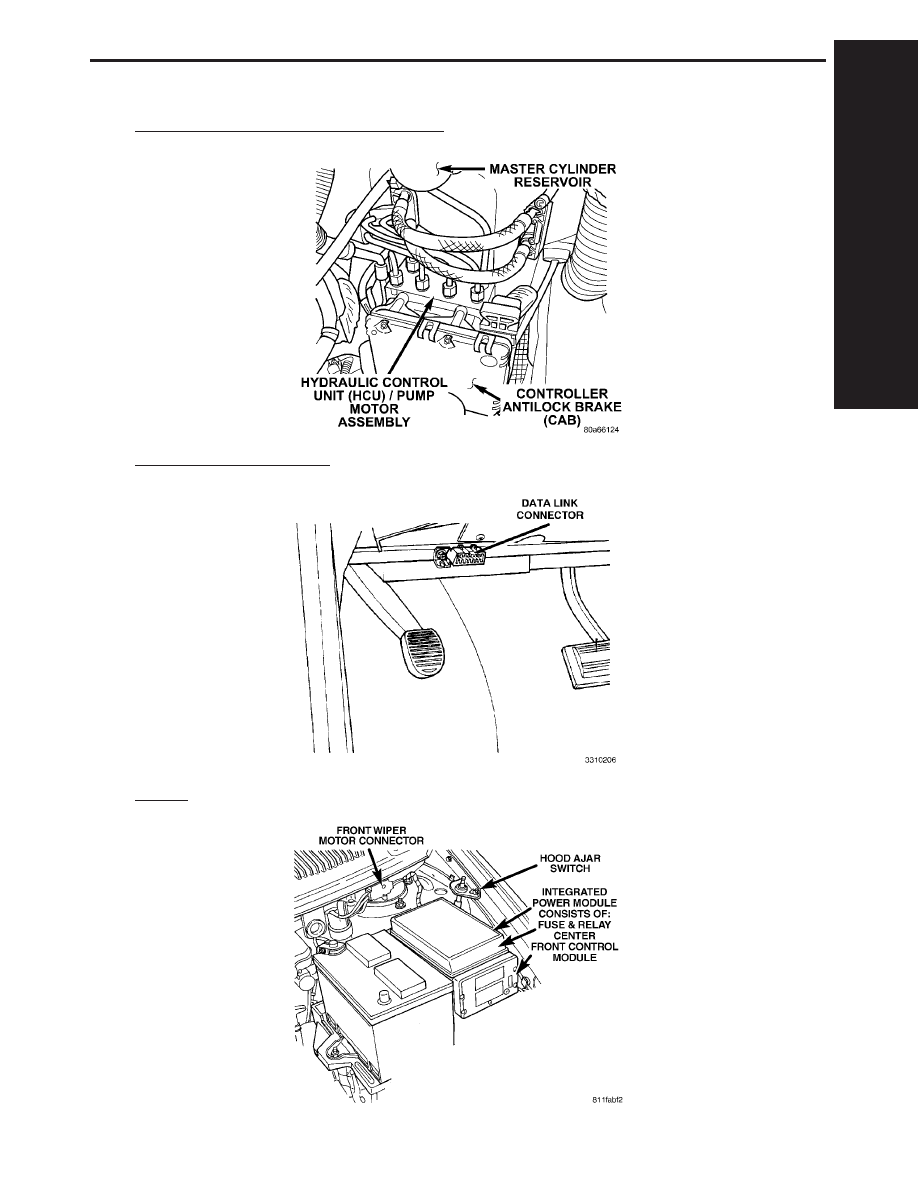
8.0
COMPONENT LOCATIONS
8.1
CONTROLLER ANTILOCK BRAKE (CAB)
8.2
DATA LINK CONNECTOR
8.3
FUSES
C
O
M
P
O
N
E
N
T
L
O
C
A
T
I
O
N
S
69
COMPONENT LOCATIONS
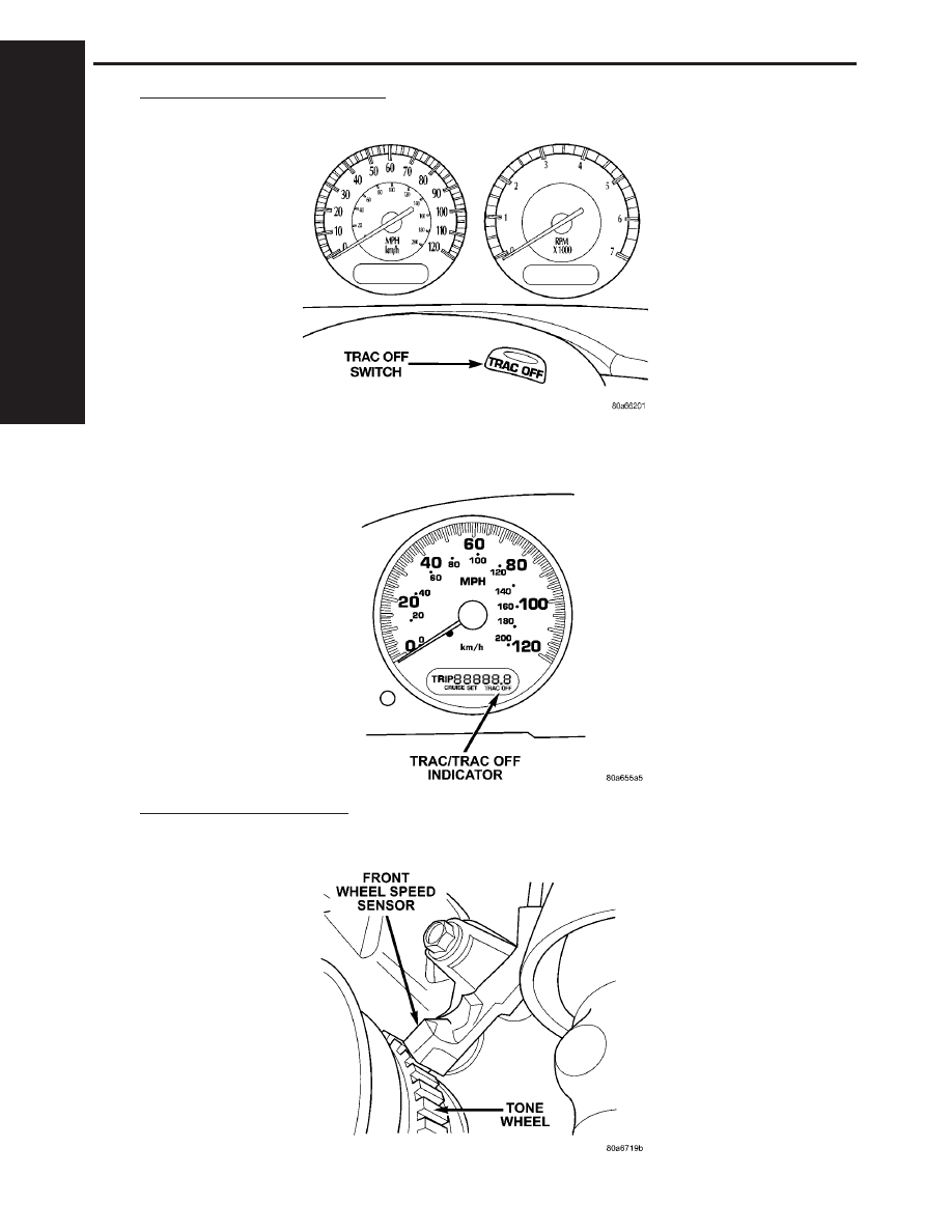
8.4
TRACTION CONTROL SWITCH
8.4.1
TRACTION CONTROL INDICATORS
8.5
WHEEL SPEED SENSORS
8.5.1
FRONT
C
O
M
P
O
N
E
N
T
L
O
C
A
T
I
O
N
S
70
COMPONENT LOCATIONS
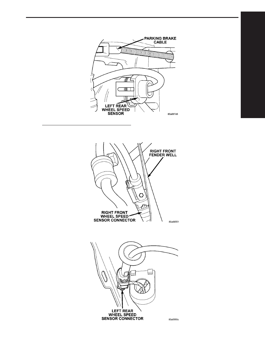
8.5.2
REAR
8.5A
WHEEL SPEED SENSOR CONNECTORS
8.5A.1
FRONT
8.5A.2
REAR
C
O
M
P
O
N
E
N
T
L
O
C
A
T
I
O
N
S
71
COMPONENT LOCATIONS
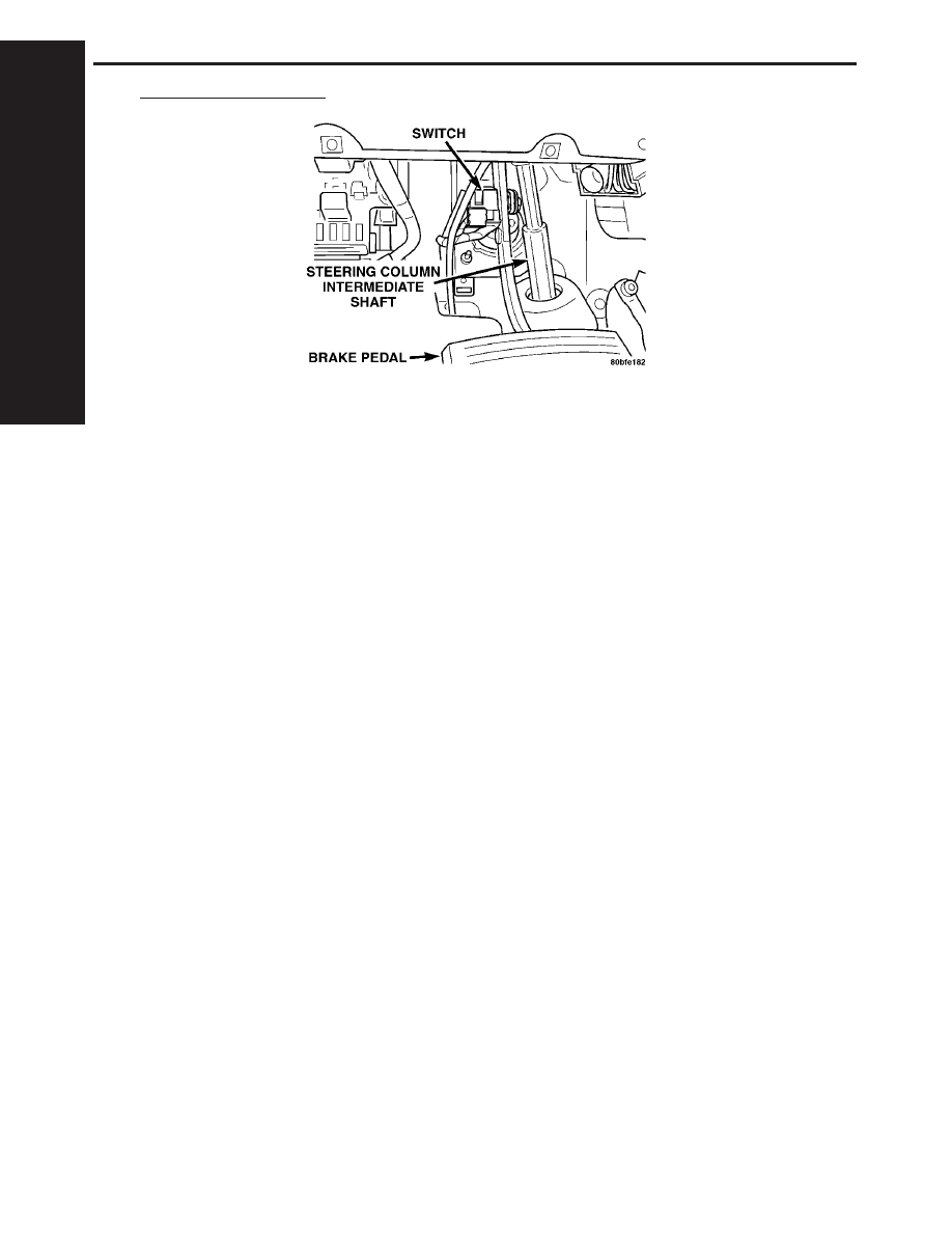
8.6
BRAKE LAMP SWITCH
C
O
M
P
O
N
E
N
T
L
O
C
A
T
I
O
N
S
72
COMPONENT LOCATIONS
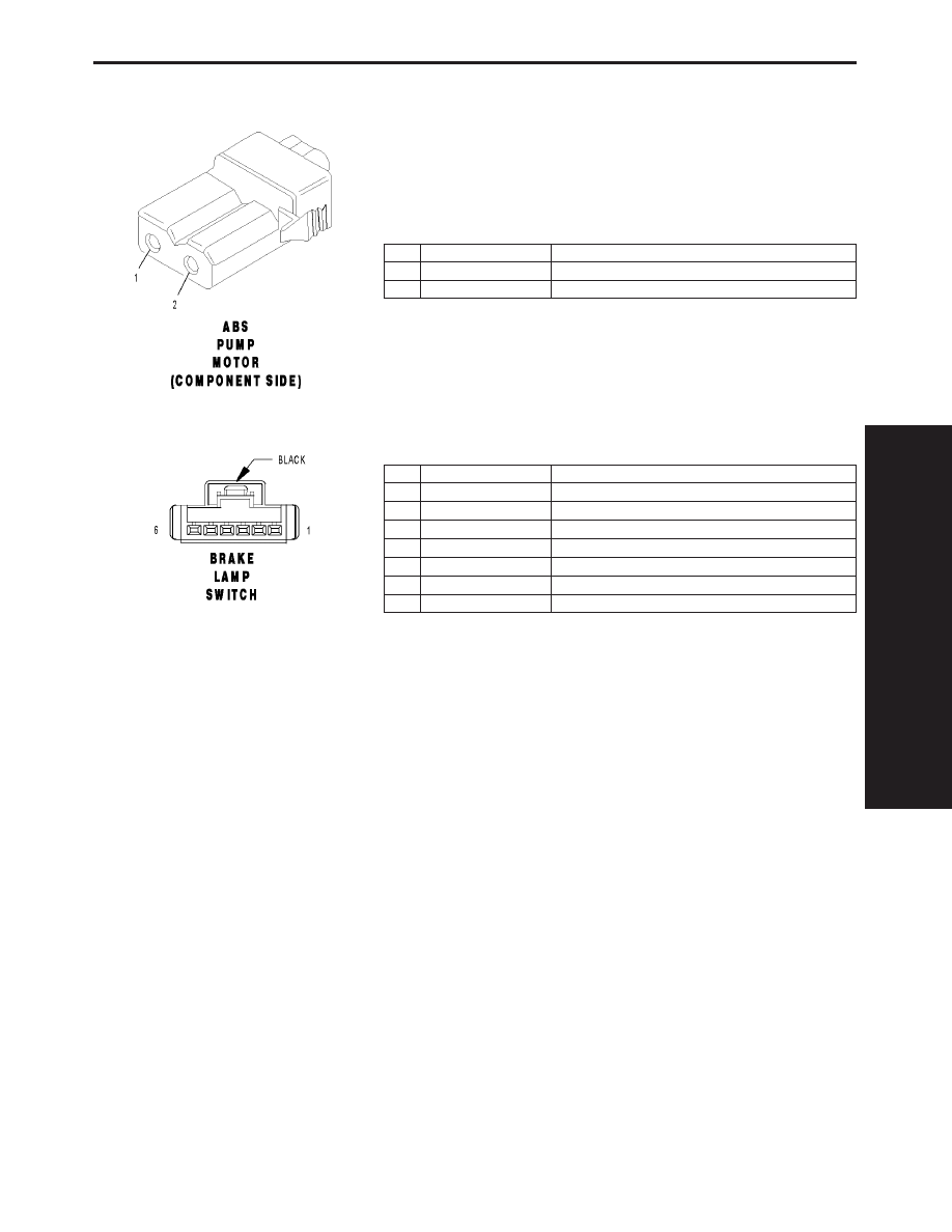
9.0
CONNECTOR PINOUTS
ABS PUMP MOTOR (COMPONENT SIDE) - 2 WAY
CAV
CIRCUIT
FUNCTION
1
-
GROUND
2
-
PUMP/MOTOR RELAY OUTPUT
BRAKE LAMP SWITCH - BLACK 6 WAY
CAV
CIRCUIT
FUNCTION
1
A103 18GY/RD
FUSED B(+)
2
L50 18WT/TN (DIESEL)
PRIMARY BRAKE SWITCH SIGNAL
2
L50 18WT/TN (GAS)
BRAKE LAMP SWITCH OUTPUT
3
V30 20VT/WT (GAS)
S/C BRAKE SWITCH OUTPUT
4
V32 20VT/YL (GAS)
SPEED CONTROL SUPPLY
5
Z429 20BK/OR
GROUND
6
B29 20DG/WT
SECONDARY BRAKE SWITCH SIGNAL
C
O
N
N
E
C
T
O
R
P
I
N
O
U
T
S
73
CONNECTOR PINOUTS
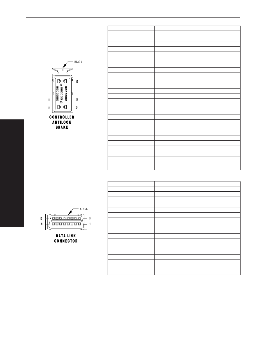
CONTROLLER ANTILOCK BRAKE - BLACK 24 WAY
CAV
CIRCUIT
FUNCTION
1
Z107 12BK/DG
GROUND
2
B1 18DG/OR
RIGHT REAR WHEEL SPEED SENSOR SIGNAL
3
B2 18DG/LB
RIGHT REAR WHEEL SPEED SENSOR 12 VOLT SUPPLY
4
-
-
5
D25 18WT/VT
PCI BUS
6
B6 18DG/WT
RIGHT FRONT WHEEL SPEED SENSOR SIGNAL
7
B7 18DG/VT
RIGHT FRONT WHEEL SPEED SENSOR 12 VOLT SUPPLY
8
-
-
9
A111 12DG/RD
FUSED B(+)
10
F500 18DG/PK
FUSED IGNITION SWITCH OUTPUT (RUN)
11
-
-
12
-
-
13
-
-
14
-
-
15
-
-
16
Z127 12BK/DG
GROUND
17
-
-
18
L50 18WT/TN (DIESEL)
PRIMARY BRAKE SWITCH SIGNAL
18
L50 18WT/TN (GAS)
BRAKE LAMP SWITCH OUTPUT
19
B3 18DG/YL
LEFT REAR WHEEL SPEED SENSOR SIGNAL
20
B4 18DG/GY
LEFT REAR WHEEL SPEED SENSOR 12 VOLT SUPPLY
21
-
-
22
B8 18DG/TN
LEFT FRONT WHEEL SPEED SENSOR SIGNAL
23
B9 18DG/WT (3.3L/3.8L)
LEFT FRONT WHEEL SPEED SENSOR 12 VOLT SUPPLY
23
B9 18DG/LG (EXCEPT
3.3L/3.8L)
LEFT FRONT WHEEL SPEED SENSOR 12 VOLT SUPPLY
24
A107 12TN/RD
FUSED B(+)
DATA LINK CONNECTOR - BLACK 16 WAY
CAV
CIRCUIT
FUNCTION
1
-
-
2
D25 20WT/VT
PCI BUS
3
-
-
4
Z11 20BK/LG
GROUND
5
Z111 20BK/WT
GROUND
6
-
-
7
D21 20WT/DG (DIESEL)
SCI TRANSMIT (ECM)
7
D21 20WT/DG (GAS)
SCI TRANSMIT (PCM)
8
-
-
9
D123 20WT/BR
FLASH PROGRAM ENABLE
10
-
-
11
-
-
12
D20 20WT/LG (GAS)
SCI RECEIVE (PCM)
13
-
-
14
-
-
15
D15 20DG/YL (EATX)
SCI TRANSMIT (TCM)
16
A105 20DB/RD
FUSED B(+)
C
O
N
N
E
C
T
O
R
P
I
N
O
U
T
S
74
CONNECTOR PINOUTS
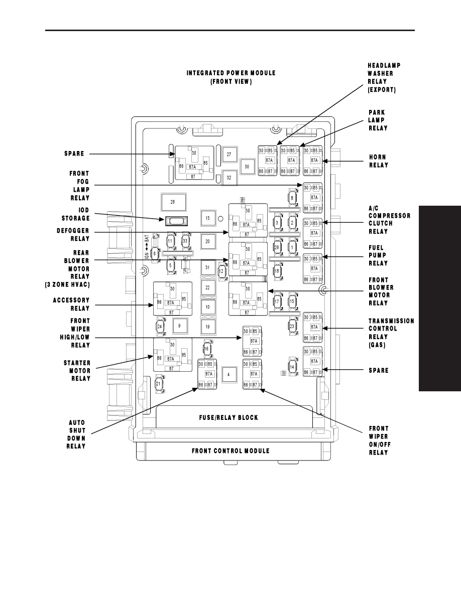
C
O
N
N
E
C
T
O
R
P
I
N
O
U
T
S
75
CONNECTOR PINOUTS
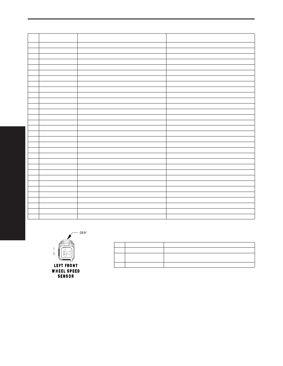
FUSES (IPM)
FUSE
NO.
AMPS
FUSED CIRCUIT
FUNCTION
1
20A
INTERNAL
FUSED B(+)
2
15A
INTERNAL
FUSED PARK LAMP RELAY OUTPUT
3
15A
INTERNAL
FUSED PARK LAMP RELAY OUTPUT
4
30A
INTERNAL
FUSED B(+)
5
20A
F306 16DB/PK
FUSED ACCESSORY RELAY OUTPUT
6
20A
F307 16LB/PK (ACCESSORY RELAY POSITION)
FUSED ACCESSORY RELAY OUTPUT
6
20A
F307 16LB/PK (BATTERY POSITION)
FUSED B(+)
8
20A
INTERNAL
FUSED B(+)
9
40A
INTERNAL
FUSED B(+)
10
40A
C7 12DB
FUSED FRONT BLOWER MOTOR RELAY OUTPUT
11
20A
F302 18GY/PK
FUSED ACCESSORY RELAY OUTPUT
12
25A
C51 12LB/BR
FUSED REAR BLOWER MOTOR RELAY OUTPUT
13
40A
C15 12DB/WT
FUSED DEFOGGER RELAY OUTPUT
14
20A
INTERNAL
FUSED B(+) (I.O.D.)
15
20A
INTERNAL (DIESEL)
FUSED B(+)
15
20A
INTERNAL (EATX)
FUSED B(+)
16
25A
INTERNAL
FUSED B(+)
17
20A
INTERNAL
FUSED B(+)
18
15A
INTERNAL
FUSED B(+)
19
40A
A101 12VT/RD
FUSED B(+)
20
30A
A102 12WT/RD
FUSED B(+)
21
25A
A111 12DG/RD
FUSED B(+)
22
40A
A110 12OR/RD
FUSED B(+)
23
10A
A106 20LB/RD
FUSED B(+)
24
20A
A701 16BR/RD
FUSED B(+) (HAZARD)
26
20A
A103 18GY/RD
FUSED B(+)
27
40A
A112 12OR/RD
FUSED B(+)
28
40A
F30 12PK/YL
FUSED IGNITION SWITCH OUTPUT (RUN-ACC)
30
40A
INTERNAL (EXPORT)
FUSED B(+)
31
40A
A113 12WT/RD
FUSED B(+)
32
40A
A115 12YL/RD
FUSED B(+)
33
15A
INTERNAL
FUSED ACCESSORY RELAY OUTPUT
LEFT FRONT WHEEL SPEED SENSOR - GRAY 2 WAY
CAV
CIRCUIT
FUNCTION
1
B9 18DG/WT (3.3L/3.8L)
LEFT FRONT WHEEL SPEED SENSOR 12 VOLT SUPPLY
1
B9 18DG/LG (EXCEPT
3.3L/3.8L)
LEFT FRONT WHEEL SPEED SENSOR 12 VOLT SUPPLY
2
B8 18DG/TN
LEFT FRONT WHEEL SPEED SENSOR SIGNAL
C
O
N
N
E
C
T
O
R
P
I
N
O
U
T
S
76
CONNECTOR PINOUTS
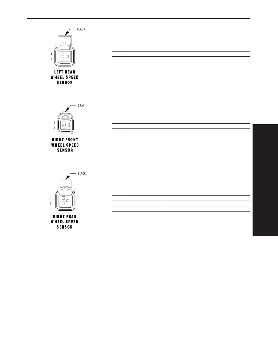
LEFT REAR WHEEL SPEED SENSOR - BLACK 2 WAY
CAV
CIRCUIT
FUNCTION
1
B4 18DG/GY
LEFT REAR WHEEL SPEED SENSOR 12 VOLT SUPPLY
2
B3 18DG/YL
LEFT REAR WHEEL SPEED SENSOR SIGNAL
RIGHT FRONT WHEEL SPEED SENSOR - GRAY 2 WAY
CAV
CIRCUIT
FUNCTION
1
B7 18DG/VT
RIGHT FRONT WHEEL SPEED SENSOR 12 VOLT SUPPLY
2
B6 18DG/WT
RIGHT FRONT WHEEL SPEED SENSOR SIGNAL
RIGHT REAR WHEEL SPEED SENSOR - BLACK 2 WAY
CAV
CIRCUIT
FUNCTION
1
B2 18DG/LB
RIGHT REAR WHEEL SPEED SENSOR 12 VOLT SUPPLY
2
B1 18DG/OR
RIGHT REAR WHEEL SPEED SENSOR SIGNAL
C
O
N
N
E
C
T
O
R
P
I
N
O
U
T
S
77
CONNECTOR PINOUTS

NOTES
78
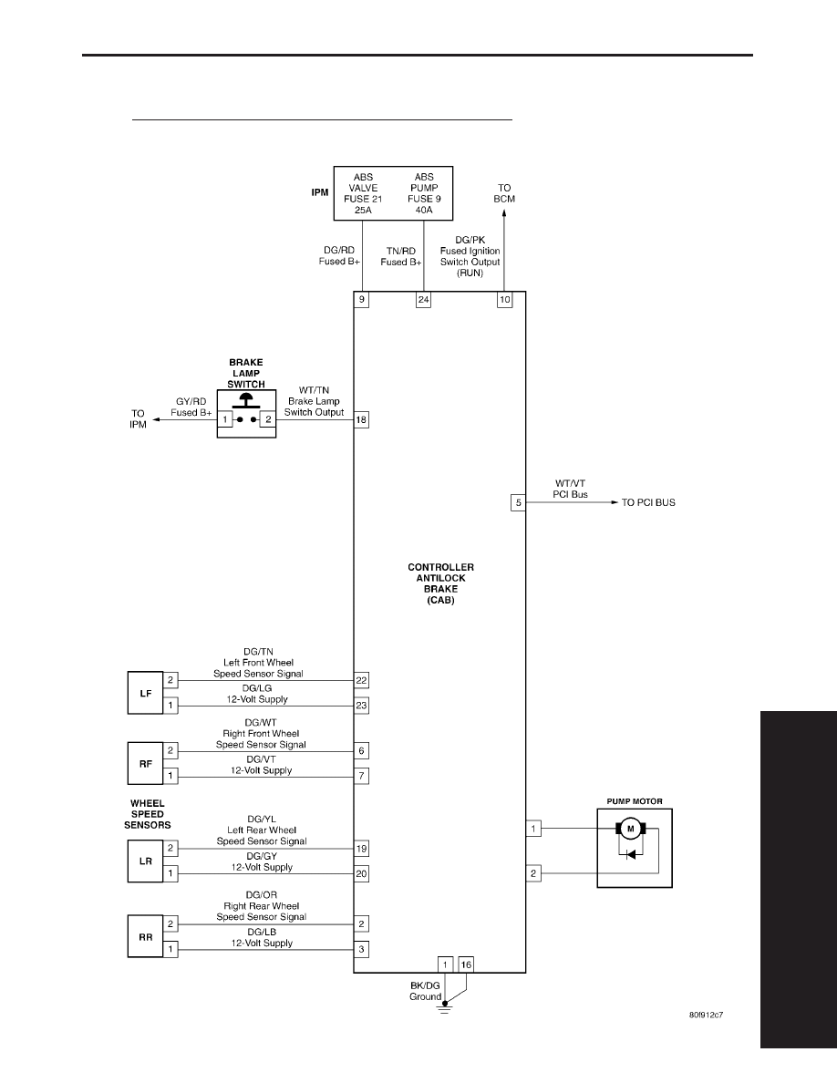
10.0
SCHEMATIC DIAGRAMS
10.1
TEVES MARK 20E ANTILOCK BRAKE SYSTEM – ABS
S
C
H
E
M
A
T
I
C
D
I
A
G
R
A
M
S
79
SCHEMATIC DIAGRAMS

NOTES
80

DIAGNOSTIC TEST PROCEDURES — TELL US!
DaimlerChrysler Corporation is constantly working to provide the technician the best diagnostic manuals possible.
Your comments and recommendations regarding the diagnostic manuals and procedures are appreciated.
To best understand your suggestion, please complete the form giving us as much detail as possible.
Model
Year
Body Type
Engine
Transmission
Vehicle Mileage
MDH
Diagnostic Procedure
Book No.
Page
Comments/recommendations (if necessary, draw sketch)
Name
Submitted by:
Address
City/State/Zip
Business Phone #
All comments become property of DaimlerChrysler Corporation and may be used without compensation.
Dealer Technical Operations
800 Chrysler Drive
CIMS 486-02-76
Auburn Hills, MI 48326-2757
Document Outline
- RS Service Manual
- RS Powertrain
- RS Body
- RS Transmission
- RS Chassis
- TABLE OF CONTENTS
- 1.0 INTRODUCTION
- 2.0 IDENTIFICATION OF SYSTEM
- 3.0 SYSTEM DESCRIPTION AND FUNCTIONAL OPERATION
- 4.0 DISCLAIMERS, SAFETY, WARNINGS
- 5.0 REQUIRED TOOLS AND EQUIPMENT
- 6.0 GLOSSARY OF TERMS
- 7.0 DIAGNOSTIC INFORMATION AND PROCEDURES
- ADJUSTABLE PEDALS
- BRAKES (CAB)
- BUS SYSTEM COMMUNICATION FAILURE
- CAB INTERNAL FAILURE
- CLUSTER LAMP FAILURE
- INCORRECT TONE WHEEL FAILURE
- LEFT FRONT SENSOR CIRCUIT FAILURE
- LEFT REAR SENSOR CIRCUIT FAILURE
- RIGHT FRONT SENSOR CIRCUIT FAILURE
- RIGHT REAR SENSOR CIRCUIT FAILURE
- LEFT FRONT WHEEL SPEED SIGNAL FAILURE
- LEFT REAR WHEEL SPEED SIGNAL FAILURE
- RIGHT FRONT WHEEL SPEED SIGNAL FAILURE
- RIGHT REAR WHEEL SPEED SIGNAL FAILURE
- PUMP CIRCUIT FAILURE
- SYSTEM OVER VOLTAGE
- SYSTEM UNDER VOLTAGE
- VALVE POWER FEED FAILURE
- *BRAKE LAMP SWITCH INOPERATIVE
- *TRAC OFF INDICATOR NEVER/ALWAYS ON
- *TRAC ON INDICATOR NEVER/ALWAYS ON
- COMMUNICATION
- VERIFICATION TESTS
- 8.0 COMPONENT LOCATIONS
- 9.0 CONNECTOR PINOUTS
- ABS PUMP MOTOR (COMPONENT SIDE) - 2 WAY
- BRAKE LAMP SWITCH - BLACK 6 WAY
- CONTROLLER ANTILOCK BRAKE - BLACK 24 WAY
- DATA LINK CONNECTOR - BLACK 16 WAY
- FUSES (IPM)
- LEFT FRONT WHEEL SPEED SENSOR - GRAY 2 WAY
- LEFT REAR WHEEL SPEED SENSOR - BLACK 2 WAY
- RIGHT FRONT WHEEL SPEED SENSOR - GRAY 2 WAY
- RIGHT REAR WHEEL SPEED SENSOR - BLACK 2 WAY
- 10.0 SCHEMATIC DIAGRAMS
- COMMENTS
Wyszukiwarka
Podobne podstrony:
2005 RG CHASSIS
Rozdzielnice stacyjne RS STS (2005)
AM1 2005 W1upg
Wytyczne ERC 2 2005
BYT 2005 Pomiar funkcjonalnosci oprogramowania
Wyklad3 2005
SWW epidem AIDS 2005
gemius 2005 zagrozenia
Świecie 14 05 2005
Walproiniany 2005
1 Podstawy diagnostyki w chorobach nerek 2005
N T 2005(fizjoterapia)
AM1 2005 W1
2005 t1
więcej podobnych podstron