Adam Paweł Zaborski
Project “The development of the didactic potential of Cracow University of Technology in the range of
modern construction” is co-financed by the European Union within the confines of the European Social Fund
and realized under surveillance of Ministry of Science and Higher Education.
13. Cross-section characteristics
Introduction
Definitions
cross-section area
∫∫
=
A
A
A
d
, [m
2
]
static moments of area (first moments of area, first moments of inertia)
∫∫
∫∫
=
=
A
z
A
y
A
y
S
A
z
S
d
d ,
, [m
3
]
gravity centre (when the calculation concerns a geometrical shape only the term centroid is used)
A
S
z
A
S
y
z
y
C
y
c
z
c
c
c
=
=
,
:
)
,
(
centroidal axis, central axis – an axis passing through the centroid (the gravity centre)
(second moments of area), inertia moments (about y and z axes and product moment)
∫∫
∫∫
∫∫
=
=
=
A
yz
A
z
A
y
A
yz
J
A
y
J
A
z
J
d
d
d
,
,
2
2
, [m
4
]
central inertia moment – inertia moments about central axis
matrix of inertia moments
−
−
z
yz
yz
y
J
J
J
J
principal central inertia moments – inertia moments resulting from the eigenvalue problem
yz
y
yz
z
y
z
y
yz
z
y
z
y
J
J
J
J
J
J
J
J
J
J
J
J
J
J
J
−
−
=
α
+
−
−
+
=
+
−
+
+
=
1
2
2
2
2
2
1
tan
,
2
2
,
2
2
,
principal central axes – such axes
2
1
, x
x
that:
→
−
−
2
1
0
0
J
J
J
J
J
J
z
yz
yz
y
principal central inertia radii
A
J
i
A
J
i
2
2
1
1
,
=
=
, [m]
ellipse of inertia – an ellipse in which half-axes are equal to principal inertia radii
polar inertia moment
∫∫
=
A
O
A
r
J
d
2
, [m
4
]
Superposition principle
Due to additivity of the double integrals, every integral may be calculated over subareas. It means that a
cross-section may be divided into simpler geometric figures and the total results are the sum of the partial
results.
Parallel axes theorem (Steiner’s formulae)
Let’s suppose the first and second inertia moments about the central axis c are known. Their values about
any parallel axis l, at distance d from central axis c, read:
d
A
S
S
c
l
⋅
+
=
,
2
d
A
J
J
c
l
⋅
+
=
Adam Paweł Zaborski
Project “The development of the didactic potential of Cracow University of Technology in the range of
modern construction” is co-financed by the European Union within the confines of the European Social Fund
and realized under surveillance of Ministry of Science and Higher Education.
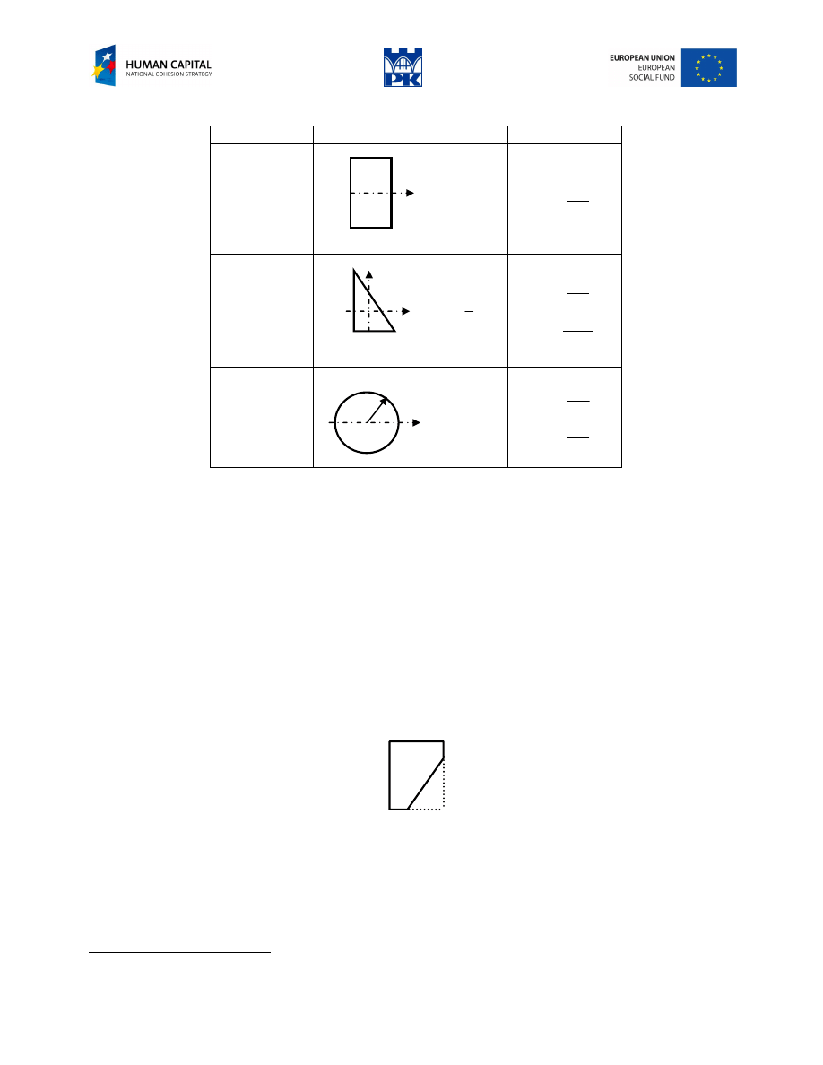
Formulae to memorize
figure
drawing
area
inertia moment
rectangle
y
h
b
bh
12
3
bh
J
y
=
right triangle
z
h
y
b
bh
2
1
36
3
bh
J
y
=
72
2
2
h
b
J
yz
−
=
1
circle
r
y
2
r
π
4
4
r
J
y
π
=
2
4
0
r
J
π
=
Table 13.1 Characteristics of basic figures – formulae to memorize
Tensor calculus conclusions
The principal inertia moments are extreme (maximal and minimal).
Every symmetry axis is the principal central axis. Second axis is perpendicular to the symmetry axis and
passes through the gravity centre.
Tip: The characteristics calculations for symmetric cross-section are simpler because we can compute
principal moments directly.
If a cross-section has more then two symmetry axes, every central axis is principal too. In that case every
central moment is also a principal one.
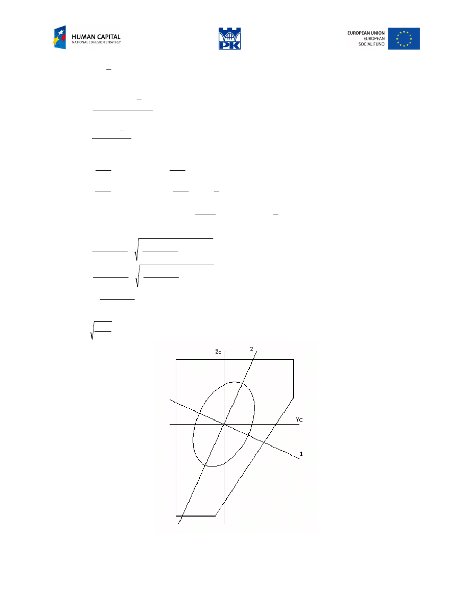
Example
Determine the geometric characteristics for the section in Fig. 13.1.
4
3
1
1
Fig. 13.1 Cross-section
Solution
The calculation is made for the rectangle “minus” the triangle.
area:
1
the sign of the product moment changes each time a reflection is made
Adam Paweł Zaborski
Project “The development of the didactic potential of Cracow University of Technology in the range of
modern construction” is co-financed by the European Union within the confines of the European Social Fund
and realized under surveillance of Ministry of Science and Higher Education.
3
2
2
1
4
3
⋅
⋅
−
⋅
=
A
gravity centre:
222
.
1
9
2
3
2
1
3
5
.
1
12
=
⋅
+
⋅
−
⋅
=
c
y
cm
333
.
2
9
3
3
1
3
2
12
=
⋅
⋅
−
⋅
=
c
z
cm
central inertia moments:
5
.
10
)
333
.
2
1
(
3
12
3
2
)
333
.
2
2
(
12
12
4
3
2
3
2
3
=
−
⋅
−
⋅
−
−
⋅
+
⋅
=
yc
J
cm
4
556
.
5
222
.
1
2
3
2
1
3
12
3
2
)
222
.
1
5
.
1
(
12
12
4
3
2
3
2
3
=
−
⋅
+
⋅
−
⋅
−
−
⋅
+
⋅
=
zc
J
cm
4
(
)
833
.
2
222
.
1
2
3
2
1
333
.
2
1
3
72
3
2
)
222
.
1
5
.
1
(
)
333
.
2
2
(
12
0
2
2
=
−
⋅
+
⋅
−
⋅
−
⋅
−
−
⋅
−
⋅
+
=
zycc
J
cm
4
principal central inertia moments and direction
79
.
11
833
.
2
2
556
.
5
5
.
10
2
556
.
5
5
.
10
2
2
1
=
+
−
+
+
=
J
cm
4
27
.
4
833
.
2
2
556
.
5
5
.
10
2
556
.
5
5
.
10
2
2
2
=
+
−
−
+
=
J
cm
4
(
)
°
−
−
==
α
→
−
=
−
−
=
α
48
.
24
4273
.
0
4553
.
0
833
.
2
5
.
10
79
.
11
tan
principal central inertia radii:
14
.
1
9
79
.
11
1
=
=
i
cm
Fig. 13.2 Inertia ellipse of the cross-section
Adam Paweł Zaborski
Project “The development of the didactic potential of Cracow University of Technology in the range of
modern construction” is co-financed by the European Union within the confines of the European Social Fund
and realized under surveillance of Ministry of Science and Higher Education.
69
.
0
9
27
.
4
2
=
=
i
cm
The inertia ellipse is shown in Fig. 13.2.
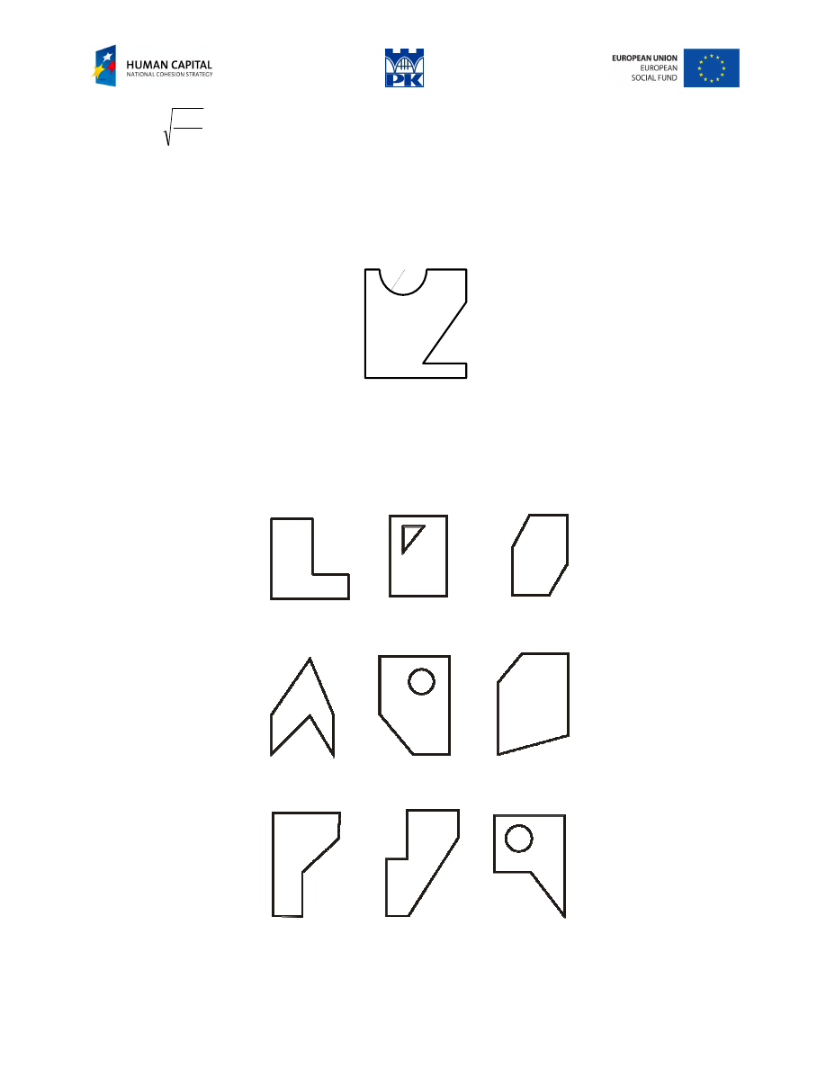
Workshop theme
Adopt numerical input data for the cross-section in Fig. 13. 3 and determine principal central inertia
moments. Draw the inertia ellipse.
r
e
e
d
c
b
a
Fig. 13.3 Cross-section to compute
Review problems
Adopt numerical input data and determine principal central inertia moments.
Fig. 13.4 Review problems

Adam Paweł Zaborski
Project “The development of the didactic potential of Cracow University of Technology in the range of
modern construction” is co-financed by the European Union within the confines of the European Social Fund
and realized under surveillance of Ministry of Science and Higher Education.
Addendum
Hints
Tip: Inertia moment about the central axis is minimal in reference to other parallel axes.
Tip: The gravity centre is always inside a circumscribed polygon.
Except for a few cases, all calculations in strength of materials are carried on with respect to the principal
central axes.
Glossary
first moment of area, static moment – moment statyczny
second moment of area, inertia moment – moment bezwładności
centroidal inertia moment, central inertia moment – centralny moment bezwładności
inertia product moment – moment dewiacji
centroid, gravity centre – środek ciężkości
centroidal axis, central axis – oś centralna
principal central axis – oś główna centralna
principal central inertia moment – główny centralny moment bezwładności
inertia radius – promień bezwładności
ellipse of inertia – elipsa bezwładności
Wyszukiwarka
Podobne podstrony:
C07 design 13 AZ
C07 design 11 AZ
C07 design 12 AZ
C07 design 08 AZ
C07 design 02 AZ
C07 design 03 AZ
C07 design 09 az
C07 design 05 AZ
C07 design 10 AZ
C07 design 06 AZ
C07 design 01 AZ
C07 design 03 AZ
C07 design 02 AZ
C07 design 09 AZ
C07 design 10 AZ
C07 design 01 AZ
C07 design 06 AZ
C07 design 08 AZ
C07 design 15 AZ
więcej podobnych podstron