Chapter 6 LSIS: XGB PLC
6-1
Chapter 6 LSIS: XGB PLC
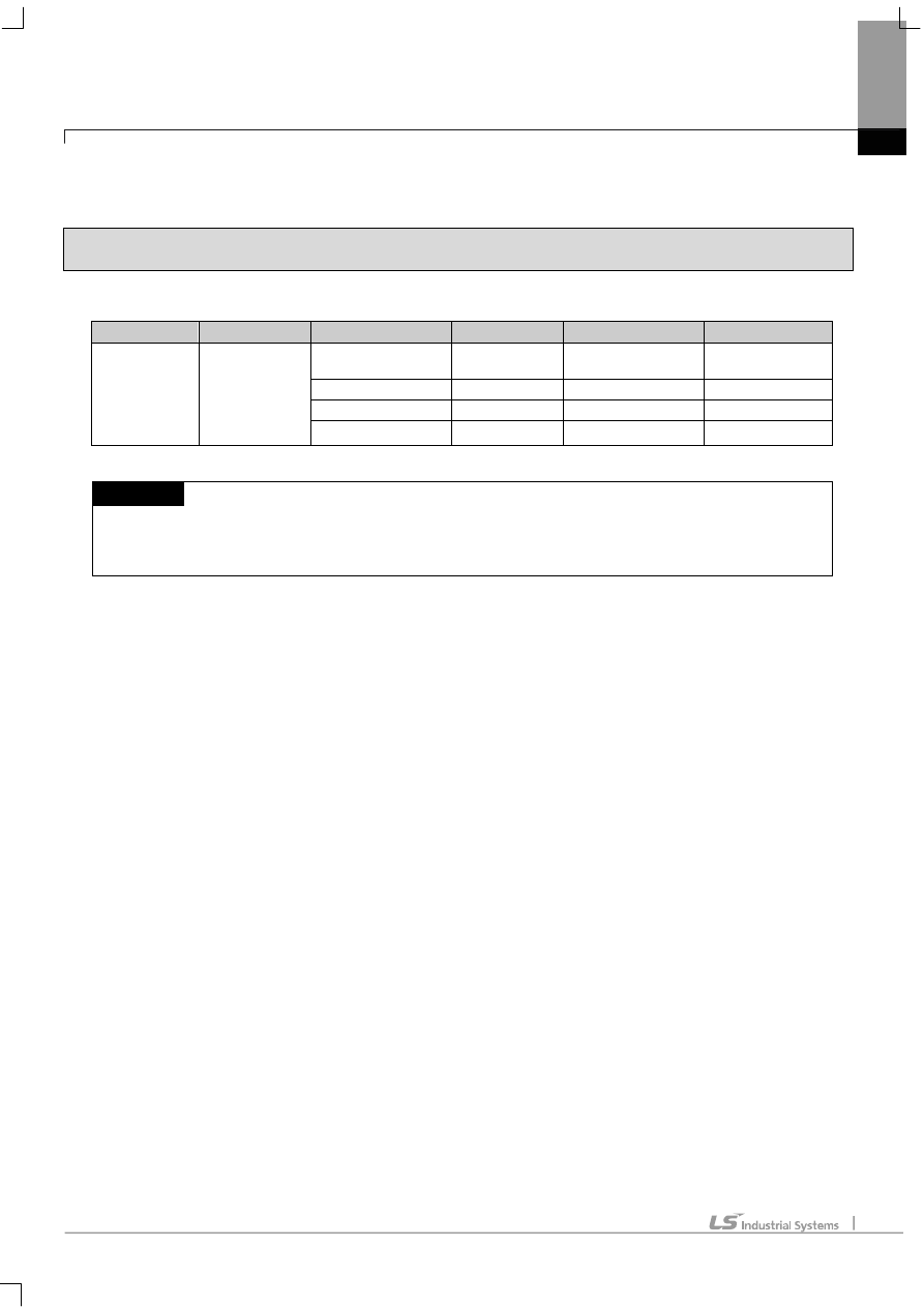
6.1 PLC List
XGT Panel is able to connect to XGB PLC.
PLC
CPU module
Connection method
Comm. method
Connection Module
Remarks
XGB
XBM-DR16S
XBM-DN16S
XBM-DN32S
CPU direct
connection
RS-232C CPU
Module
-
Link RS-232C
CPU
Module
Internal
Cnet
Link RS-485
CPU
Module
Internal
Cnet
Link RS-422/485
XBL-C41A Cnet
NOTE
(1) Terminology
► CPU module direct connection: executes serial communication through the loader port of the CPU module.
► Link: executing serial communication with the communication module of the PLC.
Chapter 6 LSIS: XGB PLC
6-2
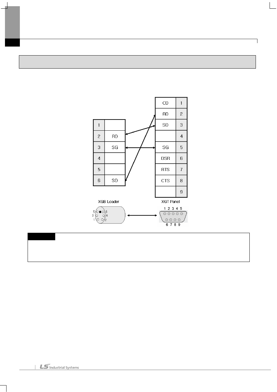
6.2 Wiring Diagram
6.2.1 CPU module direct connection method
This figure is a way to connect XGT Panel to XGK PLC with the CPU module direct connection method.
NOTE
(1) Cautions when wiring cable
► In the CPU module loader port is a CPU module that provides built-in Cnet. Be careful not to connect to other
pins when wiring.
► For your convenience, purchase a loader cable of the CPU module.
Chapter 6 LSIS: XGB PLC
6-3
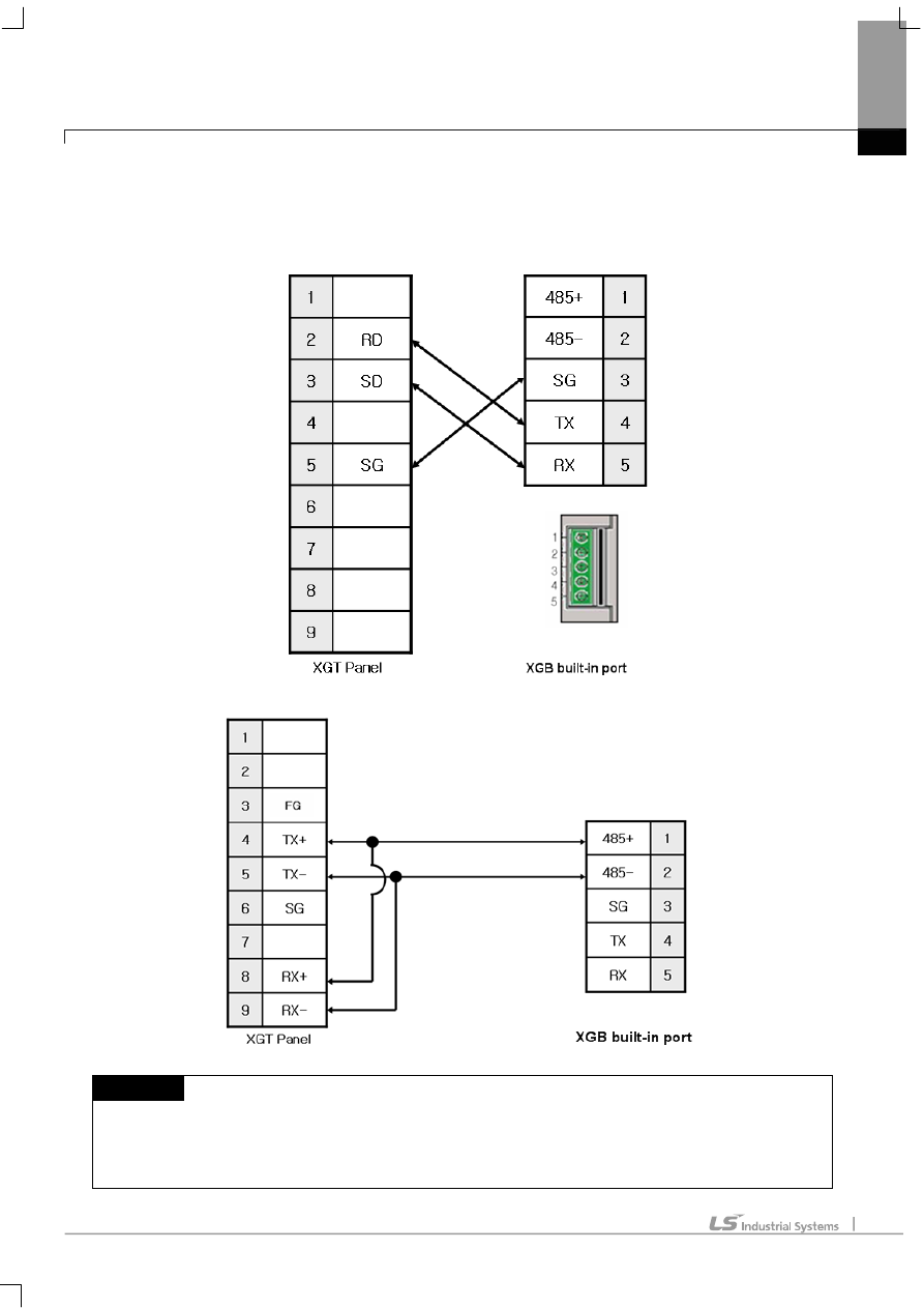
6.2.2 Link method: Built-in Cnet
Cnet is specified into RS-232C and RS-422/485 type.
Below is the wiring of RS-232C Cnet.
RS-485 wiring is as below.
NOTE
(1) Notice
► Refer to chapter 2 for shield wiring.
► Set terminal switch of the XGT Panel to wire as RS-485.
► RS-422/485 port of the PLC does not need an extra connector since it’s consisted as a terminal block.
Chapter 6 LSIS: XGB PLC
6-4
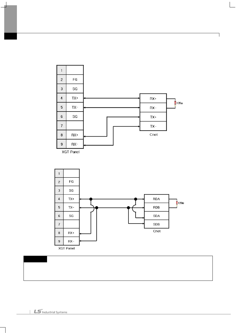
6.2.3 Link method: Cnet
Now XGB provides Cnet only for RS-422/485.
RS-422 wiring is as below.
RS-485 wiring is as below.
NOTE
(1) Notice
► Set terminal switch of the XGT Panel.
► RS-422/485 port of the PLC does not need an extra connector since it’s consisted as a terminal block.
► Refer to chapter 2 for shield wiring.
Chapter 6 LSIS: XGB PLC
6-5
6.3 Communication Setting
6.3.1 CPU module direct connection method
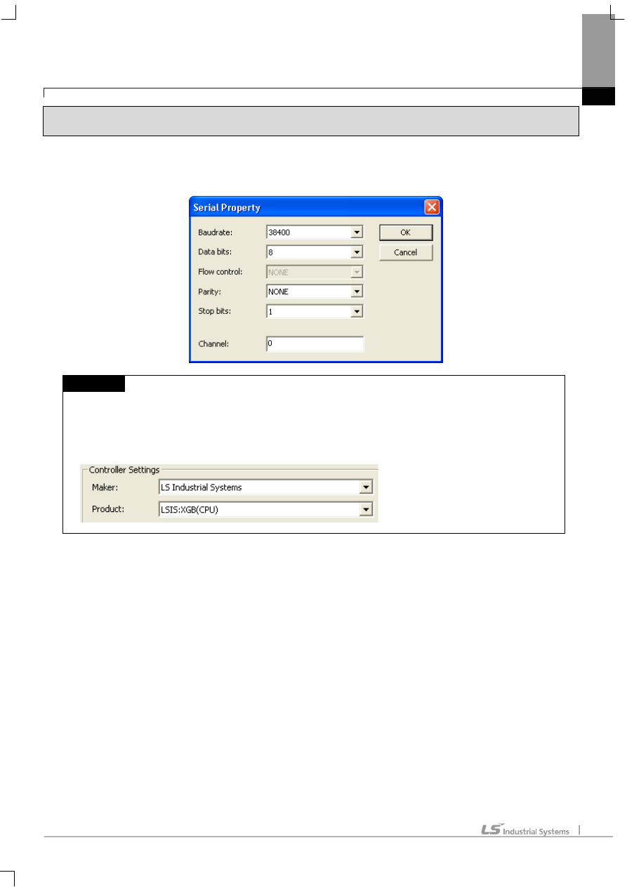
Communication parameter of the XGT Panel gets set through XP-Builder. (Refer to XP-Builder instruction manual)
XP-Builder provides communication parameter for the CPU module loader as basics.
NOTE
(1) Communication state check
► When it is unable to check the communication state with the XGK CPU module, check it by using the XGT
Panel Diagnostics and PLC Information function. (Refer to XGT Panel instruction manual)
(2) Cautions when setting XP-Builder
► When creating project and setting communication, set as below.
Chapter 6 LSIS: XGB PLC
6-6
6.3.2 Link method: Built-in Cnet
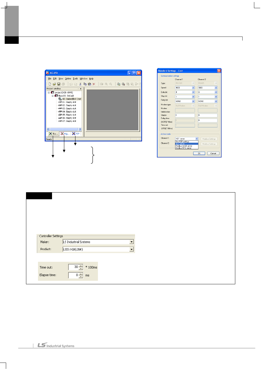
Set Cnet communication parameter of the PLC through XG-PD. (Refer to XGB Cnet instruction manual)
This is the figure of Cnet configuration. Select an internal Cnet in the basic parameter setting.
Channel 1 is for RS-232C and channel 2 is for RS-485. Set up communication parameters in each channel.
Select XGT server at the operation mode.
When write is done and PLC is reset, setting is done.
NOTE
(1) Communication state check
► XG-PD has a monitoring function. Communication data may be checked using this function.
(2) Cautions when setting PLC
► Be sure to reset the PLC after setting the communication parameter.
► This manual explains in brief. Please refer to XGB Cnet operating manual.
(3) Cautions when setting XP-Builder
► When creating project and setting communication, set as below.
► When configuring 1:N, set transmission Elapse time.
Basic Parameter Setting
High-speed Link Setting
P2P Setting
Comm. Parameter Setting
Chapter 6 LSIS: XGB PLC
6-7
6.3.3 Link method: Cnet
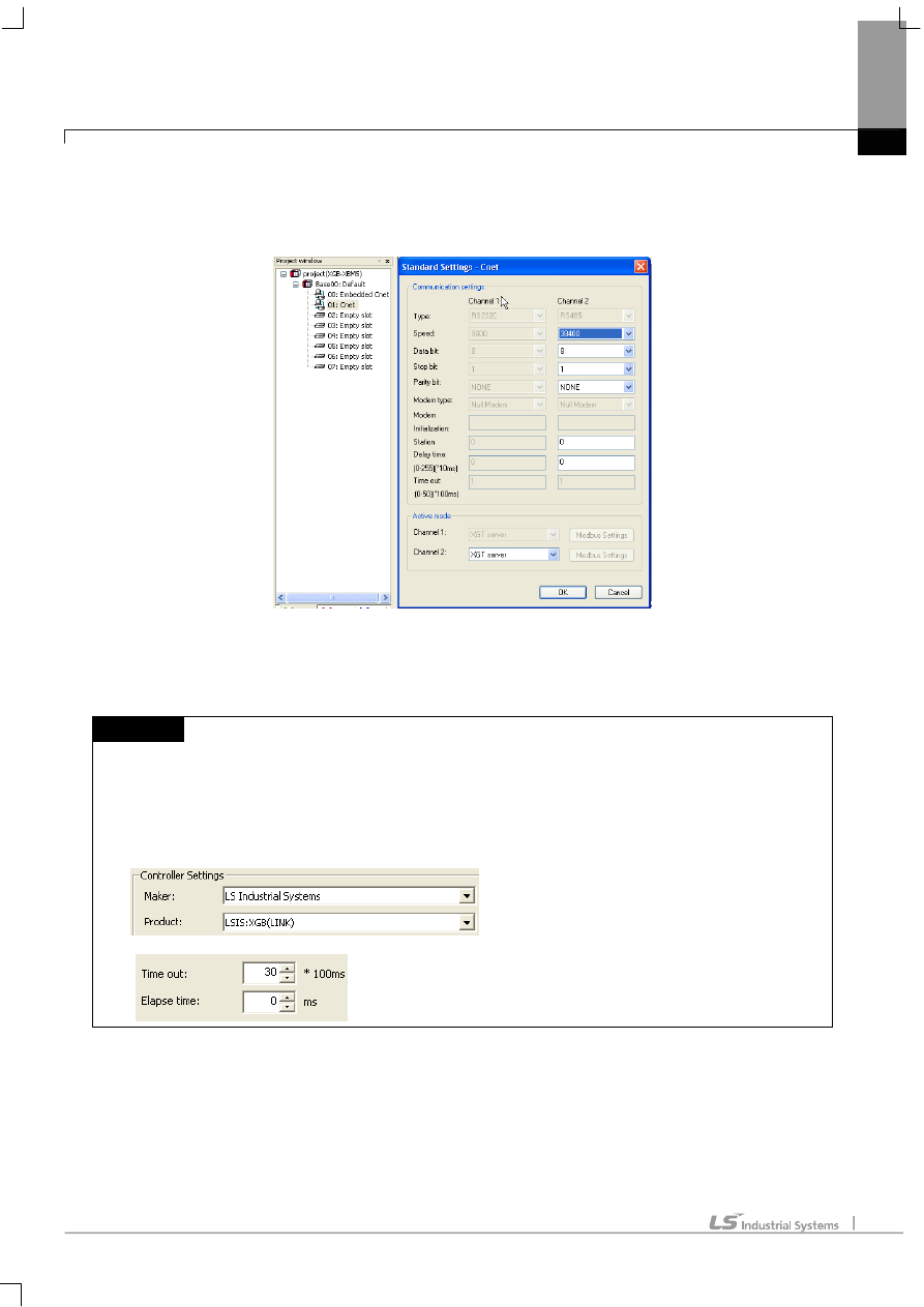
Set up Cnet communication parameters on the XG-PD. (Refer to XGT Cnet operating manual.)
This figure is about Cnet setting.
When write is done and PLC is reset, setting is done.
After completion of “Write,” then reset the PLC.
NOTE
(1) Communication state check
► XG-PD has a monitoring function. Communication data may be checked using this function.
► There are RX, TX LEDs on the Cnet module. These LEDs blink rapidly when communicating normally.
(2) Cautions when setting PLC
► Be sure to reset the PLC after setting the communication parameter.
(3) Cautions when setting XP-Builder
► When creating project and setting communication, set as below.
► When configuring 1:N, set transmission Elapse time.
Chapter 6 LSIS: XGB PLC
6-8
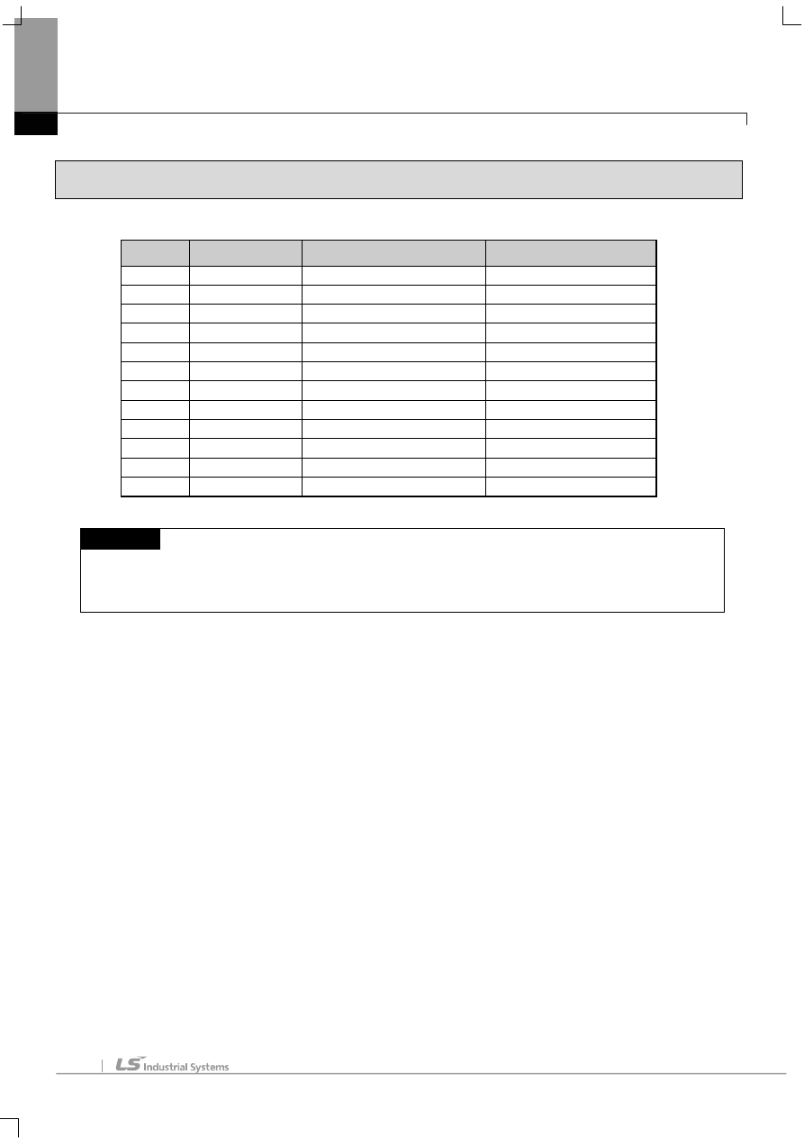
6.4 Available Device
Available devices of the XGT Panel are as below:
Area
Size
Bit points
Word data
P
2048 point
P0000 ~ P127F
P000 ~ P127
M
4096 point
M0000 ~ M255F
M000 ~ M255
K
40960 point
K00000 ~ K2559F
K0000 ~ K2559
F
4096 point
F0000 ~ F255F
F000 ~ F255
T
256 point
T000 ~ T255
T000 ~ T255
C
256 point
C000 ~ C255
C000 ~ C255
U
256 word
U00.00.0 ~ U7F.31.F
U00.00 ~ U7F.31
S
128 word
S00.00 ~ S127.99
WORD N/A
L
20480 point
L00000 ~ L1279F
L0000 ~ L1279
N
3936 word
Contact point N/A
N0000 ~ N3935
D
5120 word
D0000.0 ~ D5119.F
D0000 ~ D5119
Z
128 word
Contact point N/A
Z000 ~ Z127
NOTE
(1) Notice
► For instructions on using devices and specific information, please refer to the XP-Builder instruction manual.
► Please make sure to use the device within the range.
► Device range may differ according to the CPU module. Refer to each CPU module’s instruction manual.
Document Outline
Wyszukiwarka
Podobne podstrony:
08 czesc2 Uklady sterujace PLC
FP w 08
08 Elektrownie jądrowe obiegi
archkomp 08
02a URAZY CZASZKOWO MÓZGOWE OGÓLNIE 2008 11 08
ankieta 07 08
08 Kości cz Iid 7262 ppt
08 Stany nieustalone w obwodach RLCid 7512 ppt
ch6 030702
2009 04 08 POZ 06id 26791 ppt
08 BIOCHEMIA mechanizmy adaptac mikroor ANG 2id 7389 ppt
Prezentacja PLC
W 5g PLC LICZNIKI
Sterowniki PLC
depresja 08 09
więcej podobnych podstron