VERO UK TRAINING MATERIAL
Using profiles in VISI Modelling
Pre requisite
To attempt this course it is required that you have completed the 2D Drafting tutorial and exercises and have successfully finished the Basic Modelling guide.
Objectives
In their commonest form Profiles come in 2 distinct types, Closed profiles and Open Profiles.
To do this you will need to draw the following 2D geometry: -
STAGE 1 Draw the 2D elements on previous page
Closed Profiles by definition are a continuous chain of 2D elements where the chain forms a closed loop. As a rule, the elements that form the closed loop must all touch at their endpoints.
Creating a closed profile
Once the elements are drawn the 2D elements are created as a profile
From the Left hand screen menu, icons can be selected to vary the way in which the profile is created.

Automatically chain the elements and erase underlying geometry

The 2D elements should now have been erased and the display should show a YELLOW profile. Now Extrude the Profile into a solid .
Creating Open Profiles
Open Profiles by definition are a continuous chain of 2D elements where the first and last elements in the chain are not coincident. As a rule the elements that form the chain must all touch at their endpoints except the first and last element endpoints.
Construct the 2D elements in the drawing shown below. There is no need to add the dimensions.
Construct an Open Profile from this set of 2D elements
Choose to erase the existing 2D elements and Automatically chain the geometry.
The open set of 2D elements should have now been replaced by a YELLOW Open Profile.
More Profile Techniques
Wireframe- Profile - Quick:
This function is used to profile a closed (chain) of elements which must form a continuous closed loop.�By definition, all the end points must be touching each other.�The profile is created by simply selecting a point within the closed loop of elements.
Open the file C:\Visi19\Workf\Sample\wire\Quick profile1.wkf
Select the Quick Profile command as shown.
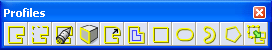
On the left side of the screen, icons will appear with the following options:

The closed 2D profiles are shown in a yellow color and the underlying elements are erased. These profiles can now be used for various purposes in VISI Modelling and VISI Machining.Here are some tips to help with the Quick Profile creation.
Any 2D geometry that is accessible from the selected point is converted into profiles.
(ii) When dealing with a complicated figure, it is appropriate to select the reference point within the vicinity of the contour.
(iii) If the contour is not closed, the system gives an error.�In this case, the gap tolerance may be adjusted to try and generate the profile.
(iv)When creating the profile, the closed contour must be entirely visible on the screen.If this is not the case, the software gives an error message.
�
(v) All the elements of the contour should lie flat on the active workplane, if the system gives an error indicating this is not the case, you can always use the function Edit / Project On WorkPlane to ensure the elements are entirely flat and lie on the workplane.
Now try the closed element contour geometry stored in the files listed below. Use the "Quick profile" command in both cases. Keep in mind the information described in the above paragraph (v)
"Quick profile2.wkf"
"Quick profile3.wkf"
Get support from the Instructor if needed!
VERO UK
1
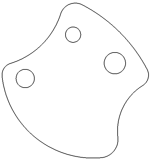
Closed Profile Example
Drawing Tip: -
It only requires 3 commands to create this contour: -
Circle/Arc-Centre Radius
Circle/Arc-Element Element Radius
Break direct
Click on Closed Profile
Click on an element to begin Profile Creation. The arrow indicates the chaining direction of the profile.
Changes the Tolerance of the allowable gap between connecting elements
Erases original 2D elements.
Inverts blends on a profile
Undo the last selected element in the profile
Automatically chains the elements
Create blends on sharp corners of a profile
Erase original 2D elements. Pick first
Automatically chain the elements
At the prompt select `Yes'
2) Pick End Element
Pick Open profile
1) Pick Start Element
Erase original 2D elements. Pick first
Automatically chain the elements
Click yes to confirm the Profile
Quick Profile
Select a reference point within the contour. Use the intersection snap from the left hand side menu.
Delete the underlying 2D elements.
Adjustable tolerance for skipping any gaps between the geometry endpoints.
Quick Profile Attributes for adding 2D CAM attributes to a profile.
Wyszukiwarka
Podobne podstrony:
Detecting metamorphic viruses using profile hidden markov models
63 907 917 Chemical Depth Profiling of Tool Materials Using Glow Discharge Optical Emission
ćw 4 Profil podłużny cieku
Profilaktyka nowotworowa
profilaktyka przeciwurazowa
Niezawodowa profilaktyka poekspozycyjna
profilaktyka nadcisnienia(2)
PROFILAKTYKA ZDROWIA
Profilaktyka przeciwzakrzepowa w chirurgii ogólnej, ortopedii i traumatologii
Profilaktyka poekspozycyjna zakażeń HBV, HCV, HIV
PROFILAKTYKA PREWENCJA A PROMOCJA ZDROWIA
3 using c
Rodzina w systemie profilaktyki na szczeblu lokalnym
Profilaktyka wirusowa dla uczniów
więcej podobnych podstron