sprintinst

|
SUPPLEMENTARY INSTRUCTIONS FOR INSTALLATION OF V.W. SPRINT KIT TO:- MICROBUS |
SPEEDWELL | |
|
- |
FITTING INSTRUCTION | |
|
TRANSPORTER |
No. 72 . 30.4. 1966 | |
|
_ |
and CARAYETTE. |
(SUPPLEMENT TO No.71 ) |
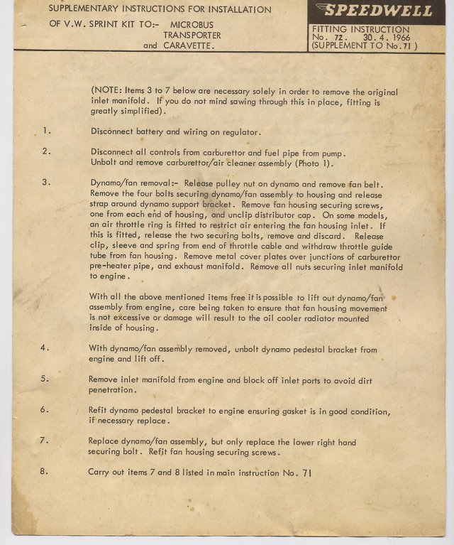
(NOTĘ: Items 3 to 7 beloware necessary solely in order to remove the original inlet manifold. If you do not mind sawing fhrough this in place, fitting is greatly simplified).
1. Disconnect battery and wiring on regulator.
2. Disconnect all Controls from carburettor and fuel pipę from pump.
Unbolt and remove carburetfor/air cleaner assembly (Photo 1).
3. Dynamo/fan remoyal:- Reloase pulley nut on dynamo and remove fan belt. Remove the four bolts securing dynamo/fan assembly to housing and release strap around dynamo support bracket. Remove fan housing securing screws, one from each eńd of housing, and unclip distributor cap. On some models, an air throttle ring is fitted to restrict air entering the fan housing inlet. If this is fitted, release the two securing bolts, remove and discard. Release clip, sleeve and spring from end of throttle cable and withdraw throttle guide tubę from fan housing. Remove metal cover plafes over junctions of carburettor pre-heater pipę, and exhaust manifold. Remove all nuts securing inlet manifold to engine .
With all the above mentioned items free itispossible to lift out dynamo/fan assembly from engine, care being taken to ertsure that fan housing movement is not excessive or damage v/i11 result to the oil cooler radiator mounted inside of housing.
4. With dynamo/fan assembly removed, unbolt dynamo pedestal bracket from engine and lift off.
5. Remove inlet manifold from engine and błock off inlet ports to avoid dirt penetration.
6. Refit dynamo pedestal bracket to engine ensuring gasket is in good condition, if necessary replace.
7. Replace dynamo/fan assembly, but only replace the lower right hand securing bolt. Refit fan housing securing screws.
8. Carry out items 7 and 8 listed inmain instruction No. 71
Wyszukiwarka
Podobne podstrony:
sprintinst SERVIC£ INSTRUCTIONS FOR V.W. SPEEDWELL INSTRUCTION No. 70 22. 6. 19ćó. Photo 1 Show
sprintinst 1 tf / YOLKSWAGEN SPRINT KIT. FITTING INSTRUCTION. No. 71. . 29. 4
15ccw03 Netscape - [<B>Manual Installation Instructions for the 1995 Grolier EncycIopedia</
PRODUCTION OF ALTERNATIYE FUEL Project goals: Installation of power linę for production of biomass
Installation of MySQL Cluster on Linux This section covers installation methods for MySQL Cluster on
Special Techniąues Instructions for Entrclac paltem: The indriidunl areas of color are worked in Moc
15ccw03 Netscape - [<B>Manual Installation Instructions for the 1995 Grolier EncycIopedia</
60577 system 31 31SPECIAL REMARKS ON THE APPLICATION OF “MY SYSTEM"Instructions for Exercising
Spis treści 7 Iwona Kumor, Lucyna Poniatowska: Allowances for revaluation of receivables as an instr
motometer instructions1 INSTALLATIOH INSTRUCTIONS • STANDARD VW SEDAN FOR MOTOMETKR 5-In-l DASH INST
ANNA sum09 USA15 SJWBWH bdtting • dried Uvendor • ffcerfi I stuffmg INSTRUCTIONS 1 For A, cut one Wt
Clydesdale (6) Instructions for working the Clydesdale MATERIAŁ USED: The original of this design wa
complete origami COMPLETETaSćm An A-Z of facts and folds, with step-by-step instrucfions f
Amigurumi Worldi The basie instructions are the same for each of the seven tiny omis piet U rod. The
więcej podobnych podstron