2224357280
NS/GS
9 - 58 ENGINE-
REMOVAL AND INSTALL ATI ON (COfltmued)
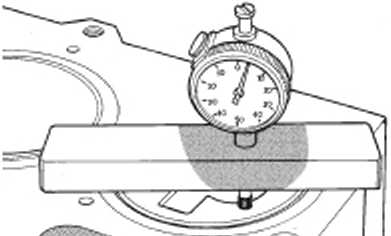

Fig. 30 Mess uring Platon Protmaion
|
Maos-cod denara*^ |«rri....... Cjf. Kood gada* k cmsi (mu) .. Fnkso <Wc*Ke h*nl |
...........053-0.62 ...........142 080 089 |
|
.SVcs.rod cfcnoW |rvrj |
063 072 |
|
C>4 Kfod rjariH kcln*M (rtm] |
.......... 1 62 |
|
Foton iUcscsku frrm|...... |
...........083-089 |
|
,SVr.ł.'i« drr*t-*<T* |—r| |
. 073-082 |
|
ł*uJ yodii rłitlrcu . .. |
...........1-62 |
|
Pvstoo docror>:o |mt|. .......... |
...........050-0.89 |
J95C9.16*
exwi;
(3) Zoro tho dlal Indicator on tho cyllndor błock matlr\g surface.
(4) Setup tho dlal Indfcatcr on tho plston crown labovo lho contor of tho plstcn pin) Smm (\f8 In.) from lho odge cł tho plston and noto tho moasuremont iF>g. 21).
)5) Ropoat tho proceduro wtth tho reet cf tho cyl-Indors.
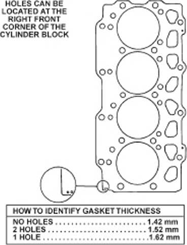
(6) Establksh tho thlcknoss of tho gaskot for aII four cy linder haads on tho basls of tho groatost plston prccruslcn (Fig. 32).
Fig. 31 Platon Proiruaion Chart
INSTALLATION CYLINDER HEAD
(1) Ramowo tho shop towols from tho <ylIndor boros. Coat tho bor os wlth cloan cngine o)l.
(2) I nst.il I cyllndor hoad allgnmont studs (VM-10O9i.
(3) After doterrolnlng tho corroct hw*d gaskec thlcknoss. chan tho błock and hsod mat Ing surfaces. pbco tho ongi no cylinder hcod gaskec ovor tho dow-ols.
(4) Pbco tho engino cy llndor hoad ovor tho dwob.
CAUTlON: Engine cylinder head bo<t8 can be
reueed up to tnree tlmes.
Fig 32 Hesd GaaJc&t ktontifleation
(5) Tlghton tho origlno cyllndor hoad bolts In sequonco actordlng to tho foliowi ng proceduro (Fig.
33):
a. Tho threods and undorslde haods of tho bolts shaild bo lubrlcatod. Uso tho cyllndor hoad allgn mont studs tool numbor VM-1009. Posltlon tho haods on tho bbek and socuro wtth tho ton largo contor bolts and spacors (clamps). flngor tlght only.
b. Ertsuro that tho varlous clamps aro Irtstallod corroctly and tho hoad gaskot rema In In tholr propor posil ton. complotoly cowored. Thon. lubrlcato and lnstaII tho olght smali bolts. also flngor tlght.
(6) Looson asscmbly oll food hno for rockor arm assombllea
(7) Install tho Intako and earhaust manlfokis wlth now gaskots. partia iły t|ghtonlng tho nuts to a max-imum of 5 N m (44 In. Ibs). Thls will al)gn tho haods (rofor to Group 11. Exhaust System and Intako Man-ifold for tho propor procoduros). Install lift oyo and brak© vacuum tubo at thks tlmo.
(8) Thsn. t)ghton tho 12mm bolts wlth spoć lal tool VM-1019 In tho followlng mannor:
(9) Ist Phasc: Tlghtonlng Heod Bolts lT|g 33). Central bolts (A-L): Tlghten all bolts. start! ng wlth boli A thon RC-D-E-F-C-H-I L. to 30 N m. Ropaot tho operatłen wlth tho samo torquo. Follcwlng tho samo soquonc© rota to oach bolt threugh an anglo of
Wyszukiwarka
Podobne podstrony:
Suzuki RM125p 5-6 ENGINE REMOVAL AND INSTALLATION • Remove the cotter pin ® and br
18581 Suzuki RM125g ENGINE REMOVAL AND INSTALLATION 5-3ENGINE REMOYAL AND INSTALLATIONREMOVAL ♦ &nbs
Suzuki RM125f 5-2 ENGINE REMOVAL AND INSTALLATIONEXTERIOR PARTS ! / 7*" K&q
Suzuki RM125h 5-4 ENGINE REMOVAL AND INSTALLATION • Remove the exhaust pipę fiłting springs with the
Suzuki RM125r 5-8 ENGINE REMOVAL AND INSTALLATIONINSTALLATION • Reassemble the rem
36818 Suzuki RM125q ENGINE REMOVAL AND INSTALLATION 5-7 engine mounting bolts and plates swlngarm pi
39359 Suzuki RM125s ENGINE REMOVAL AND INSTALLATION 5-9 * Reassemble the drive Chain clip so the sli
25719 Suzuki RM125i ENGINE REMOVAL AND INSTALLATION 5-5 ♦ Disconnect the radiator
ENGINE COOLING SYSTEM _Water Pump_ REMOVAL AND INSTALLATION • When removing water
BRAKE HYDRAULIC LINĘ .Inspection.Removal and Installation. CAUTION: a. When removi
SMREAR DRUM BRAKE (LT18B) ___Removal and Installation- of Adjuster When installing, measure inner di
więcej podobnych podstron