5441336667
HALDOR TORSOE U
7/20
Latest developments in ammonia production technology

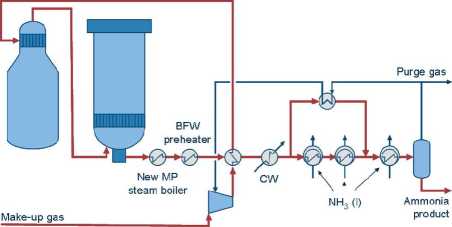
Figurę 5. Layout of synthesis loop in M.W. Kellogg-designed plant with S-50 converter
Phase II
- Installation of a S-50 radial flow corwerter with internal electric start-up heater and lower heat exchanger, and MP waste heat boiler in the loop in series with the existing converter
- Drying of make-up gas and synthesis loop re-piping
- Replacement of HP and LP rotors in synthesis gas compressor with kick-back cooler for synthesis gas compressor recycle stage
- Installation of a new boiler feed water coil in the waste heat section of the primary reformer
- Modification of ID fan turbinę
4.1.2 S-50 converter - Kalol plant
The original ammonia synthesis loop contains an existing ammonia converter unit with built-in feed/effluent exchanger. After the revamp, the exit gas from the existing converter is sent direct to the new S-50 converter at a temperaturę of approx. 325°C. After the S-50 converter a new MP steam boiler is installed. See Figurę 5.
As the inlet temperaturę to the S-50 converter is lower than the required inlet temperaturę to the catalyst bed, an S-50 converter with a lower heat exchanger is applied.
RESEARCH | TECHNOLOGY | CATALYSTS
Wyszukiwarka
Podobne podstrony:
HALDOR TORSOE U 1 / 20 Latest developments in ammonia production technology by Svend Erik Nielsen Ha
HALDOR TORSOE U 8/20 Latest developments in ammonia production technology The S-50 converter consist
HALDOR TOPSDE U 9/20 Latest developments in ammonia production technology 4.1.3 IFFCO, Kalol energy
HALDOR TOPSDE U 11/20 Latest developments in ammonia production technology Figurę 7. HTER internat b
HALDOR TOPSDE [T 13/20 Latest developments in ammonia production technology Figurę 10. NH3 plant ref
HALDOR TOPSDE U 15/20 Latest developments in ammonia production technology Figurę 11. Layout of ammo
HALDOR TOPSDE U 16/20 Latest developments in ammonia production technology Figurę 12. Corwentional s
HALDOR TOPSDE U 2/20 Latest developments in ammonia production technology 2 Latest developments in a
HALDOR TOPSDE U 3/20 Latest developments in ammonia production technology 3 New developments Two mai
HALDOR TOPSDE [T 4/20 Latest developments in ammonia production technology installed as shown in Fig
HALDOR TOPSDE U 5/20 Latest developments in ammonia production technology The HTER-p is heated by th
HALDOR TOPSDE U 10/20 Latest developments in ammonia production technology The RCF, Trombay V revamp
HALDOR TOPSDE U 12/20 Latest developments in ammonia production technology During the test-run, it w
HALDOR TOPSDE [T 17/20 Latest developments in ammonia production technology 7.2 ATR Scheme - 5000
HALDOR TOPSDE U 18/20 Latest developments in ammonia production technology 7.3 Autothermal reformer
HALDOR TOPSOE CE 19/20 Latest developments in ammonia production technology importance. For further
HALDOR TOPSDE U Latest developments in ammonia production technology
Theoretical and practical skills of a wide rangę of technologies in food production - technolog
więcej podobnych podstron