5441336654
HALDOR TOPSDE [T
13/20
Latest developments in ammonia production technology

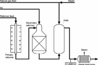
Figurę 10. NH3 plant reforming section with HTER
The parallel option can be executed in two ways: either the effluent from the secondary reformer (or ATR) is mixed with the reformed gas coming out of the HTER catalyst bed before cooling of the combined product gas, or the two streams are cooled separately and mixed at the exit. Both ways have their advantages, and the selection of option depends on the circumstances. For the revamp case at Sasol Synfuels, the first option was chosen. In other cases where a Iow CH4 leakage is crucial such as in synthesis gas production for ammonia, the second option is the most attractive.
The HTER design can be madę to accommodate both the above options and otherwise be optimised to suit the process requirements in the best possible way. The main features of the HTER will in all cases be the same as those demonstrated industrially at the Sasol Synfuels Gas Reforming Plant. The HTER suited for an ammonia plant will be madę up of a number of double tubes that are furnished with a bayonet return tubę. The heat transfer is laid out in such a way that only a very limited surface area will be subjected to metal dusting conditions, and consequently, the use of special materials can be minimised.
To illustrate a revamp situation for an ammonia plant, a comparison between a base case and the revamp case is madę in the below table. As can be seen, a 25% increase in reforming capacity and equivalent ammonia production can be achieved by introduction of the HTER. It is noted that this capacity increase could equally well be translated into an unchanged capacity and a correspondingly smaller load on the primary reformer.
RESEARCH | TECHNOLOGY | CATALYSTS
Wyszukiwarka
Podobne podstrony:
HALDOR TOPSDE U 11/20 Latest developments in ammonia production technology Figurę 7. HTER internat b
HALDOR TOPSDE U 15/20 Latest developments in ammonia production technology Figurę 11. Layout of ammo
HALDOR TOPSDE U 16/20 Latest developments in ammonia production technology Figurę 12. Corwentional s
HALDOR TOPSDE U 12/20 Latest developments in ammonia production technology During the test-run, it w
HALDOR TOPSDE [T 17/20 Latest developments in ammonia production technology 7.2 ATR Scheme - 5000
HALDOR TOPSDE U 18/20 Latest developments in ammonia production technology 7.3 Autothermal reformer
HALDOR TORSOE U 7/20 Latest developments in ammonia production technology Figurę 5. Layout of synthe
HALDOR TOPSDE U 9/20 Latest developments in ammonia production technology 4.1.3 IFFCO, Kalol energy
HALDOR TOPSDE U 10/20 Latest developments in ammonia production technology The RCF, Trombay V revamp
HALDOR TOPSDE U 2/20 Latest developments in ammonia production technology 2 Latest developments in a
HALDOR TOPSDE U 3/20 Latest developments in ammonia production technology 3 New developments Two mai
HALDOR TOPSDE [T 4/20 Latest developments in ammonia production technology installed as shown in Fig
HALDOR TOPSDE U 5/20 Latest developments in ammonia production technology The HTER-p is heated by th
HALDOR TORSOE U 1 / 20 Latest developments in ammonia production technology by Svend Erik Nielsen Ha
HALDOR TOPSOE CE 19/20 Latest developments in ammonia production technology importance. For further
HALDOR TORSOE U 8/20 Latest developments in ammonia production technology The S-50 converter consist
HALDOR TOPSDE U Latest developments in ammonia production technology
95 (100) 9 : Flea allergy dermatitis Figurę 9:9: Extensive eosinophilic plaques in a cat with FAD Fi
Theoretical and practical skills of a wide rangę of technologies in food production - technolog
więcej podobnych podstron