Chapter 2 Part B: XU series engine
in-car engine repair procedures
Contents
Camshaft oil seal(s) - renewal 9
Camshaft(s) and followers - removal, Inspection and refitting 10
Compression test - description and interpretation 2
Crankshaft oil seals - renewal 16
Crankshaft pulley - removal and refitting 5
Cylinder head - removal and refitting 12
Cylinder head cover - removal and refitting 4
Engine assembly/valve timing holes - general information and
usage 3
Engine oil and filter renewal See Chapter 1
Engine oil level check See Chapter 1
Engine/transmission mountings - inspection and renewal 18
Degrees of difficulty
Flywheel/driveplate - removal, inspection and refitting 17
General engine checks See Chapter 1
General information 1
Oil cooler (1998 cc 16-valve models) - removal and refitting 15
Oil pump - removal, inspection and refitting 14
Sump - removal and refitting 13
Timing belt - general information, removal and refitting 7
Timing belt covers - removal and refitting 6
Timing belt tensioner and sprockets - removal, inspection
and refitting ; 8
Valve clearances - checking and adjustment 11
Easy, suitable for
novice with little
experience
Fairly easy, suitable
for beginner with
some experience
Fairy difficult, suitable
for competent DIY
mechanic
Difficult, suitable for
experienced DIY
mechanic
Very difficult,
suitable for expert DIY
or professional
Specifications
Engine (general)
Designation:
1580 cc engine XU5
1761 cc engine XU7
1905 cc engine XU9
1998 cc engines XU10
Engine codes*:
1580 cc engine without a catalytic converter B4A (XU5M 2K, XU5M 3K or XU5M 4K)
1580 cc engine with a catalytic converter BDY (XU5M 3L/Z)
1761 cc engine LFZ (XU7JP L/Z)
1905 cc engine without a catalytic converter D6E (XU9JA K)
1905 cc engine with a catalytic converter DKZ (XU9JA Z)
1998 cc 8-valve engine RFX (XU10J2C LZ)
1998 cc 16-valve engine RFY (XU10J4 LZ)
Bore:
1580 cc, 1761 cc and 1905 cc engines 83.00 mm
1998 cc engines 86.00 mm
Stroke:
1580 cc engine 73.00 mm
1761 cc engine 81.00 mm
1905 cc engine 88.00 mm
1998 cc engines 86.00 mm
Direction of crankshaft rotation Clockwise (viewed from the right-hand side of vehicle)
No 1 cylinder location At the transmission end of block
Compression ratio:
1580 cc engine 8.95 :1
1761 cc engine 9.25 :1
1905 cc engine 9.2 :1
1998 cc 8-valve engine 9.5 :1
1998 cc 16-valve engine 10.4 :1

2B•2 XU series engine in-car engine repair procedures
Engine (general) (continued)
Maximum power:
1580 cc engine 88.5 bhp (65 kW) @ 6400 rpm
1761 cc engine 100.8 bhp (74 kW) @ 6000 rpm
1905 cc engine:
Without catalytic converter 127.3 bhp (93.5 kW) @ 6000 rpm
With catalytic converter 119.8 bhp (88 kW) @ 6000 rpm
1998 cc 8-valve engine 121.1 bhp (89 kW) @ 5750 rpm
1998 cc 16-valve engine 151.8 bhp (111.6 kW) @ 6500 rpm
Maximum torque:
1580 cc engine 131.2 Nm (96.8 Ibf ft) @ 3000 rpm
1761 cc engine 156.8 Nm (115.7 Ibf ft) @ 3000 rpm
1905 cc engine:
Without catalytic converter 165 Nm (121.8 Ibf ft) @ 3250 rpm
With catalytic c o n v e r t e r . . . . 153.8 Nm (113.5 Ibf ft) @ 3000 rpm
1998 cc 8-valve engine 180 Nm (133.1 Ibf ft) @ 2750 rpm
1998 cc 16-valve engine 186.6 Nm (137.7 Ibf ft) @ 3500 rpm
*The engine code is either stamped on a plate attached to the front right-hand end of the cylinder block (next to the engine mounting), or
stamped directly onto the front face of the cylinder block (just to the left of the oil filter). This is the code most often used by Citroen. The full
code given in brackets is the factory identification number, and is not often referred to by Citroen or this manual.
Camshaft
Drive Toothed belt
No of bearings 5
Cam lift:
1580 cc engine 9.7 mm
1905 cc engine 11.5 mm
1761 and 1998 cc engines Not available
Camshaft bearing journal diameter (outside diameter):
1580 cc and 1905 cc models:
No 1 26.980 to 26.959 mm
No2 27.480 to 27.459 mm
No 3 27.980 to 27.959 mm
No 4 28.480 to 28.459 mm
No 5 35.975 to 35.950 mm
1761 cc and 1998 cc models Not available
Cylinder head bearing journal diameter (inside diameter):
1580 cc and 1905 cc models:
No 1 27.000 to 27.033 mm
No 2 27.500 to 27.533 mm
No 3 28.000 to 28.033 mm
No 4 28.500 to 28.533 mm
No 5 36.000 to 36.039 mm
1761 cc and 1998 cc models Not available
Note: At the time of writing, no camshaft specifications were available for the 1761 cc and 1998 cc models.
Valve clearances
Inlet 0.20 mm
Exhaust 0.40 mm
Lubrication system
Oil pump type Gear-type, chain-driven off the crankshaft right-hand end
Minimum oil pressure at 90°C 4.5 bars at 4000 rpm
Oil pressure warning switch operating pressure 0.8 bars
Torque wrench settings Nm ibf ft
1580cc, 1761 cc and 1905 cc engines
Cylinder head cover nuts/bolts 10 7
Timing belt cover bolts 8 6
Crankshaft pulley retaining bolt 110 81
Timing belt tensioner:
Semi-automatic timing belt tensioner:
Retaining nuts ..... ... 16 12
Cam spindle locknut 13 10
Manually-adjusted tensioner pulley bolt 20 15
Camshaft sprocket retaining bolt 35 26
Camshaft bearing cap nuts 15 11
Crankshaft sprocket retaining bolt 110 81

XU series engine in-car engine repair procedures 2B•3
1580 cc, 1761 cc and 1905 cc engines (continued) Nm lbf ft
Cylinder head bolts:
Stage 1 60 44
Fully slacken all bolts, then tighten to:
Stage 2 20 15
Stage 3 Angle-tighten through 300° Angle-tighten through 300°
Sump retaining bolts 16 12
Oil pump retaining bolts 13 10
Flywheel/driveplate retaining bolts 50 37
Big-end bearing cap nuts:
Stage 1 40 30
Fully slacken all nuts, then tighten to:
Stage 2 20 15
Stage 3 Angle-tighten through 70° Angle-tighten through 70°
Main bearing cap nuts/bolts:
Retaining nuts/bolts 54 40
Centre bearing cap side bolts 23 17
Front oil seal carrier bolts 16 12
Engine/transmission right-hand mounting:
Mounting bracket retaining nuts 45 33
Engine/transmission left-hand mounting:
Mounting bracket-to-body bolts 25 18
Mounting stud 50 37
Centre nut 80 59
Engine/transmission rear mounting:
Mounting assembly-to-block bolts 45 33
Mounting bracket-to-mounting bolt 50 37
Mounting bracket-to-subframe bolt 50 37
1998 cc 8-valve and 16-valve engines
Cylinder head cover nuts/bolts 10 7
Timing belt cover bolts 8 6
Crankshaft pulley retaining bolt(s):
8-valve engine 110 81
16-valve engine 27 20
Crankshaft sprocket retaining bolt - 16-valve engine 110 81
Timing belt tensioner:
8-valve engine 20 15
16-valve engine (both pulley bolt and backplate bolts) 20 15
Camshaft sprocket retaining bolt:
8-valve engine 35 26
16-valve engine 45 33
Camshaft bearing cap nuts/bolts:
8-valve engine 16 12
16-valve engine 10 7
Cylinder head bolts:
Stage 1 40 30
Stage 2 75 55
Stage 3 Angle-tighten through 165° Angle-tighten through 165°
Sump retaining bolts 1.6 12
Oil pump retaining bolts 13 10
Flywheel/driveplate retaining bolts 50 37
Big-end bearing cap nuts:
Stage 1 40 30
Fully slacken all nuts, then tighten to:
Stage 2 20 15
Stage 3 Angle-tighten through 70° Angle-tighten through 70°
Main bearing cap bolts 70 52
Piston oil jet spray tube bolt 10 7
Front oil seal carrier bolts 16 12
Engine/transmission right-hand mounting:
Mounting bracket retaining nuts/bolts 45 33
Curved retaining plate 20 15
Engine/transmission left-hand mounting:
Mounting bracket-to-body bolts 25 18
Mounting stud 50 37
Centre nut 80 59
Engine/transmission rear mounting:
Mounting assembly-to-block bolts 45 33
Mounting bracket-to-mounting bolt 50 37
Mounting bracket-to-subframe bolt 50 37

2B•4 XU series engine in-car engine repair procedures
1 General information
How to use this Chapter
This Part of Chapter 2 describes those
repair procedures that can reasonably be
carried out on the XU series engine (1580 cc
"and larger), while it remains in the car. If the
engine has been removed from the car and is
being dismantled as described in Part C, any
preliminary dismantling procedures can be
ignored. Refer to Part A for information on the
TU series engine (1124 cc and 1360 cc).
Note that, while it may be possible
physically to overhaul items such as the
piston/connecting rod assemblies while the
engine is in the car, such tasks are not usually
carried out as separate operations. Usually,
several additional procedures (not to mention
the cleaning of components and of oilways)
have to be carried out. For this reason, all
such tasks are classed as major overhaul
procedures, and are described in Part C of
this Chapter.
Part C describes the removal of the
engine/transmission unit from the vehicle, and
the full overhaul procedures that can then be
carried out.
XU series engine description
The XU series engine is a well-proven
engine which has been fitted to many
previous Citroen and Peugeot vehicles. The
engine is of the in-line four-cylinder type,
mounted transversely at the front of the car.
The clutch and transmission are attached to
its left-hand end. The ZX range is available
with 1580 cc, 1761 cc, 1905 cc, 1998 cc
8-valve, and 1998 cc 16-valve versions of the
XU series engine. The 1998 cc 16-valve
engine is of the DOHC (double overhead
camshaft) type; all the others are SOHC
(single overhead camshaft) engines.
The crankshaft runs in five main bearings.
Thrustwashers are fitted to No 2 main bearing
cap, to control crankshaft endfloat.
The connecting rods rotate on horizontally-
split bearing shells at their big-ends. The
pistons are attached to the connecting rods
by gudgeon pins. On 1998 cc 16-valve
models, the gudgeon pins are a sliding fit in
the connecting rod, and are secured in
position with circlips. On all other models,
they are an interference fit in the connecting
rod small-end eyes. The aluminium alloy
pistons are fitted with three piston rings - two
compression rings and an oil control ring.
On 1580 cc, 1761 cc and 1905 cc models,
the cylinder block is of the "wet-liner" type.
The cylinder block is cast in aluminium alloy,
and the bores have replaceable cast-iron
liners that are located from their top ends.
Sealing O-rings are fitted at the base of each
liner, to prevent the escape of coolant into the
sump.
On all 1998 cc models (both 8- and 16-
valve), the engine is of the conventional "dry-
liner" type. The cylinder block is cast in iron,
and no separate bore liners are fitted.
On 1998 cc 16-valve models, both inlet and
exhaust camshafts are driven by a toothed
timing belt. The camshafts operate the sixteen
valves via self-adjusting hydraulic tappets
(fitted to the cam followers), thus eliminating
the need to manually adjust the valve
clearances. Both camshafts run in bearing
caps which are bolted to the top of the
cylinder head. The inlet and exhaust valves
are each closed by coil springs, and operate
in guides pressed into the cylinder head.
On all other models, the camshaft is driven
by a toothed timing belt, and it operates the
eight valves via followers located beneath
each cam lobe. The valve clearances are
adjusted by shims, positioned between the
followers and the tip of the valve stem. The
camshaft runs in bearing caps which are
bolted to the top of the cylinder head. The
inlet and exhaust valves are each closed by
coil springs, and operate in guides pressed
into the cylinder head. Both the valve seats
and guides can be renewed separately if
worn.
On all models, the water pump is driven by
the timing belt.
Lubrication is by means of an oil pump
which is driven (via a chain and sprocket) off
the crankshaft right-hand end. It draws oil
through a strainer located in the sump, and
then forces it through an externally-mounted
filter into galleries in the cylinder
block/crankcase. From there, the oil is
distributed to the crankshaft (main bearings)
and camshaft. The big-end bearings are
supplied with oil via internal drillings in the
crankshaft; the camshaft bearings also
receive a pressurised supply. The camshaft
lobes and valves are lubricated by splash, as
are all other engine components. On 1998 cc
16-valve models, an oil cooler is mounted
beneath the oil filter cartridge, to keep the oil
temperature constant under severe operating
conditions. The oil cooler is supplied with
coolant from the engine cooling system.
Throughout the manual, it is often necessary
to identify the engines not only by their cubic
capacity, but also by their engine code. The
engine code, consisting of three letters (eg.
RFY), is stamped on a plate attached to the
front right-hand end of the cylinder block, next
to the right-hand engine/transmission
mounting. Otherwise, the engine code may be
stamped directly onto the front face of the
cylinder block, on the machined surface
located just to the left of the oil filter (next to
the crankcase vent hose union).
Repair operations possible with
the engine in the car
The following work can be carried out with
the engine in the car:
(a) Compression pressure - testing.
(b) Cylinder head cover - removal and
refitting.
(c) Crankshaft pulley - removal and refitting.
(d) Timing belt covers - removal and refitting.
(e) Timing belt - removal, refitting and
adjustment.
(f) Timing belt tensioner and sprockets -
removal and refitting.
(g) Camshaft oil seal(s) - renewal.
(h) Camshaft(s) and followers - removal,
inspection and refitting,
(i) Valve clearances - checking and
adjustment.
(j) Cylinder head - removal and refitting,
(k) Cylinder head and pistons -
decarbonising.
(I) Sump - removal and refitting,
(m) Oil pump - removal, overhaul and refitting,
(n) Crankshaft oil seals - renewal,
(o) Engine/transmission mountings -
inspection and renewal,
(p) Flywheel/driveplate - removal, inspection
and refitting,
(q) Oil cooler (1998 cc 16-valve models) -
removal and refitting.
2 Compression test -
description and interpretation
Refer to Part A, Section 2.
Note: Do not attempt to rotate the engine
whilst the crankshaft/camshaft are locked in
position. If the engine is to be left in this state
for a long period of time, it is a good idea to
place suitable warning notices inside the
vehicle, and in the engine compartment. This
will reduce the possibility of the engine being
accidentally cranked on the starter motor,
which is likely to cause damage with the
locking pins in place.
1 On all models, timing holes are drilled in the
camshaft sprocket(s) and crankshaft pulley.
The holes are used to align the crankshaft and
camshaft(s), to prevent the possibility of the
valves contacting the pistons when refitting
the cylinder head, or when refitting the timing
belt. When the holes are aligned with' their
corresponding holes in the cylinder head and
cylinder block (as appropriate), suitable
diameter pins can be inserted to lock both the
camshaft and crankshaft in position,
preventing them rotating unnecessarily.
Proceed as follows.
2 Remove the timing belt upper cover as
described in Section 6.
3 Apply the handbrake, jack up the front of
the car and support it on axle stands. Remove
the right-hand front roadwheel.
4 From underneath the front of the car, prise
out the two retaining clips and remove the
plastic cover from the wing valance, to gain
3 Engine assembly/valve
timing holes -
general information and usage
XU series engine in-car engine repair procedures 2B•5
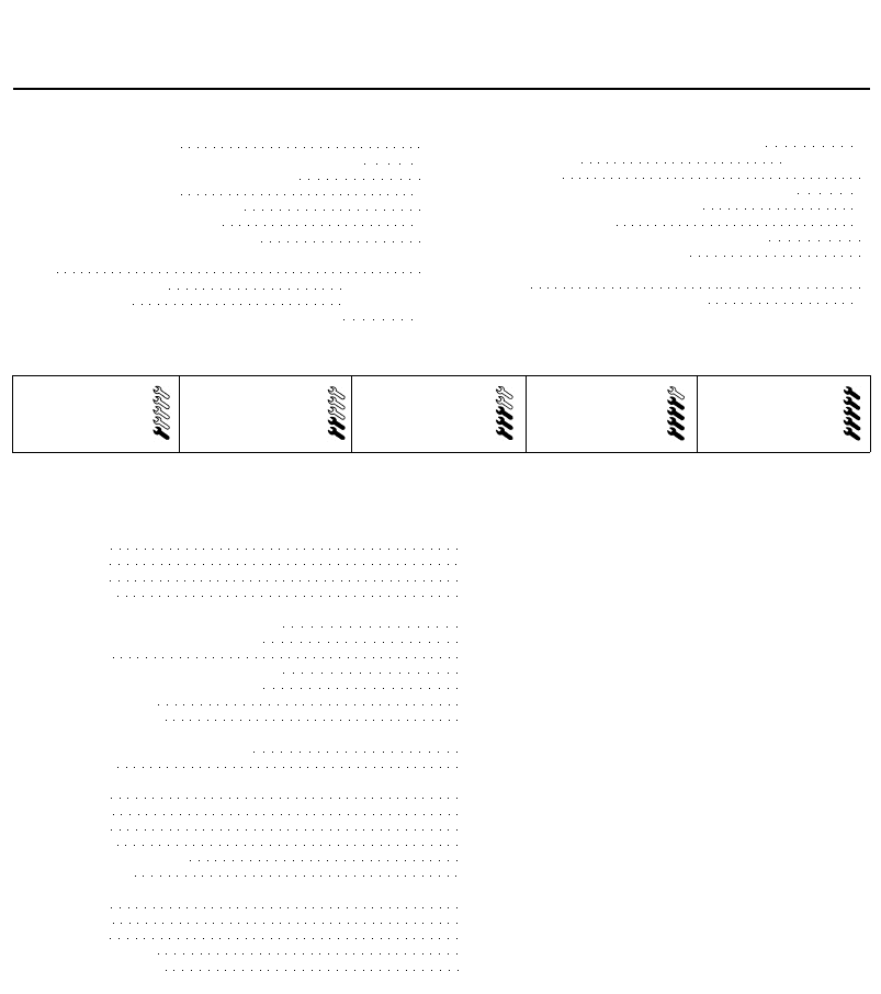
3.7 Camshaft sprocket locking pins in
position (arrowed) -1998 cc 16-valve
models
access to the crankshaft pulley bolt. Where
necessary, unclip the coolant hoses from the
bracket, to improve access further. The
crankshaft can then be turned using a suitable
socket and extension bar fitted to the pulley
bolt. Note that the crankshaft must always be
turned in a clockwise direction (viewed from
the right-hand side of vehicle).
1998 cc 16-valve models
5 Rotate the crankshaft pulley until the timing
holes in both camshafts are aligned with their
corresponding holes in the cylinder head. The
holes are aligned when the inlet camshaft
sprocket hole is in the 8 o'clock position, and
the exhaust camshaft sprocket is in the
6 o'clock position, when viewed from the
right-hand end of the engine.
6 With the camshaft sprocket holes correctly
positioned, insert a 6 mm diameter bolt (or a
drill of suitable size), through the timing hole in
the crankshaft pulley, and locate it in the
corresponding hole in the end of the cylinder
block. Note that it may be necessary to rotate
the crankshaft slightly, to get the holes to
align.
7 With the crankshaft pulley locked in
position, insert a 6 mm diameter bolt (or a drill)
through the timing hole in each camshaft
sprocket, and locate it in the cylinder head.
Note that the special Citroen locking pins are
actually 8 mm in diameter, with only their ends
stepped down to 6 mm to locate in the
cylinder head (see illustration). To simulate
this, wrap insulation tape around the outer
end of the bolt or drill, to build it up until it is a
snug fit in the camshaft hole.
8 The crankshaft and camshafts are now
locked in position, preventing unnecessary
rotation.
All other models
9 Rotate the crankshaft pulley until the timing
hole in the camshaft sprocket is aligned with
its corresponding hole in the cylinder head.
Note that the hole is aligned when the
sprocket hole is in the 8 o'clock position,
when viewed from the right-hand end of the
engine.
10 On early 1580 cc and 1905 cc models
having a semi-automatic timing belt tensioner,
3.13 Camshaft sprocket and crankshaft
pulley locking pins in position (1580 cc
model shown)
a 10 mm diameter bolt (or a drill of suitable
size) will be required to lock the crankshaft
pulley in position.
11 On later 1580 cc and 1905 cc models,
and all 1761 and 1998 cc 8-valve models
(which have a manually-adjusted timing belt
tensioner pulley) the pulley can be locked in
position with an 8 mm diameter bolt or drill.
The special Citroen locking pin is actually
10 mm in diameter, with only its end stepped
down to 8 mm to locate in the cylinder block.
To simulate this, wrap insulation tape around
the outer end of the bolt/drill, to build it up
until it is a snug fit in the pulley hole.
12 With the camshaft sprocket holes
correctly positioned, insert the required bolt or
drill through the timing hole in the crankshaft
pulley, and iocate it in the corresponding hole
in the end of the cylinder block. Note that it
may be necessary to rotate the crankshaft
slightly, to get the holes to align.
13 With the crankshaft pulley locked in
position, insert the appropriate bolt or drill
through the timing hole in the camshaft
sprocket and locate it in the cylinder head
(see illustration).
14 The crankshaft and camshaft are now
locked in position, preventing unnecessary
rotation.
4.4 Where original Citroen hose clips are
still fitted, cut them off and discard them
Removal
1 Disconnect the battery negative lead.
1580 cc and 1905 cc models
2 On 1580 cc models, remove the air cleaner-
to-throttle body duct, and the air cleaner
housing, as described in Chapter 4.
3 On 1905 cc models, remove the air cleaner
housing as described in Chapter 4, and
position the intake duct clear of the cylinder
head cover.
4 On all models, slacken the retaining clip
and disconnect the breather hose from the
top of the cylinder head cover. Where the
original crimped-type Citroen hose clip is still
fitted, cut it off and discard it. Replace it with
4.5 On 1580 cc and 1905 cc models, undo
the retaining bolts/nuts and position the
HT lead retaining clips clear of the head
cover
a standard worm-drive hose clip on refitting
(see illustration).
5 Undo the two nuts/bolts securing the HT
lead retaining bracket to the cylinder head,
and position the bracket clear of the head
cover (see illustration).
6 Slacken and remove the two remaining
cylinder head cover retaining bolts, along with
their sealing washers.
7 Lift off the cylinder head cover, and remove
it along with its rubber seal. Examine the seal
for signs of damage and deterioration, and if
necessary, renew it. Also examine the
retaining bolt sealing washers for signs of
damage, and renew if required.
1761 cc and 1998 cc 8-valve models
8 Slacken the retaining clips, and disconnect
the breather hoses from the front right-hand
end of the cover. Where the original crimped-
type Citroen hose clips are still fitted, cut
them off and discard them; use standard
worm-drive hose clips on refitting.
9 Slacken the retaining clip, and disconnect
the air cleaner-to-throttle housing duct from
the front of the cylinder head cover. Also
remove the intake duct from the left-hand side
of the head cover.
10 Release the two retaining clips, then undo
the two retaining screws located at the front,
and remove the air cleaner element cover
from the cylinder head cover. Remove the air
cleaner element, and store it with the cover.
4 Cylinder head cover -
removal and refitting
2B•6 XU series engine in-car engine repair procedures
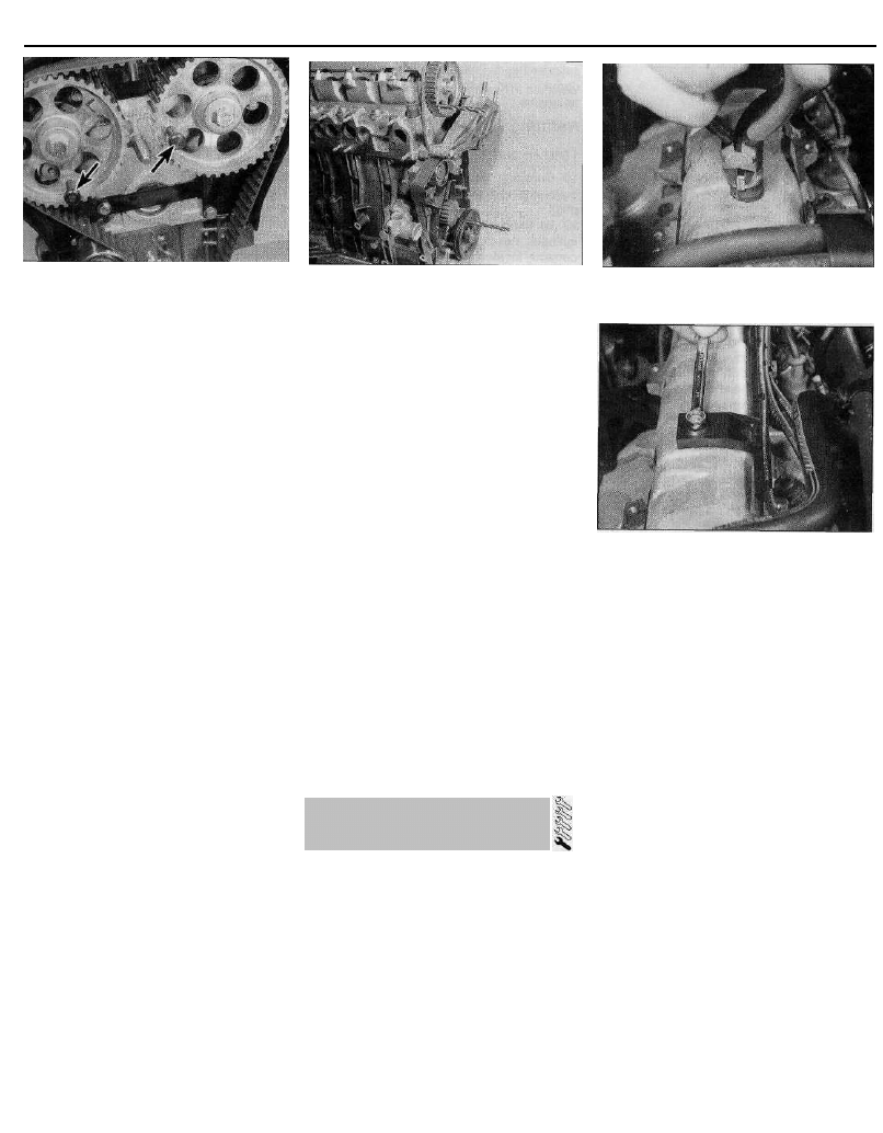
4.11 Cylinder head cover retaining nuts
(arrowed) -1761 cc and 1998 cc 8-valve
models
11 Slacken and remove the ten cylinder head
cover retaining nuts, lift off the cylinder head
cover, and remove it along with its rubber seal
(see illustration). Examine the seal for signs
of damage and deterioration, and if
necessary, renew it.
1998 cc 16-valve models
12 Refer to the information given in Chapter
4 on depressurising the fuel system. Slacken
the retaining clips, and disconnect the fuel
feed and return hoses from their unions at the
front of the head cover. Where the original
crimped-type Citroen hose clips are still fitted,
cut them off and discard them; use standard
worm-drive hose clips on refitting. Plug both
the hose and fuel rail ends, to prevent the
possible entry of dirt into the fuel system. Mop
up any spilt fuel.
13 Undo the retaining nut and bolt securing
the fuel hose retaining clips to the top of the
cylinder head cover, and remove both clips.
Position both fuel hoses clear of the head
cover, so that they do not hinder the removal
procedure.
14 Slacken and remove the remaining seven
retaining bolts, and lift the spark plug access
cover off the cylinder head cover.
15 Pull each ignition HT coil off its spark
plug. Trace the coil wiring back to its
connector on the left-hand end of the cylinder
head. Rotate the locking ring anti-clockwise,
disconnect it from the main wiring loom, and
remove the wiring and coils as an assembly.
16 Disconnect the breather hose from the
left-hand end of the cylinder head. Any
original crimped-type hose clips can be
discarded, as already mentioned.
17 Slacken and remove the twelve cylinder
head cover retaining bolts, noting the correct
fitted positions of any brackets or clips. Note
that the bolts are of four different lengths, and
it is important that each is refitted in the
correct position. To avoid confusion on
refitting, remove each bolt in turn, and store it
in its correct fitted position by pushing it
through a clearly-marked cardboard template.
18 Lift off the cylinder head cover, and
remove it along with its rubber seal. Recover
the four spark plug hole sealing rings from the
cylinder head. Examine all seals for signs of
damage and deterioration, and renew as
necessary.
Refitting
1580 cc and 1905 cc models
19 Carefully clean the cylinder head and
cover mating surfaces, and remove all traces
of oil.
20 Fit the rubber seal over the edge of the
cylinder head cover, ensuring that it is
correctly located along its entire length.
21 Carefully refit the cylinder head cover to
the engine, taking great care not to displace
the rubber seal.
22 Check that the seal is correctly located,
then refit the cover retaining bolts and sealing
washers (not forgetting to position the HT lead
bracket under the centre bolt head), and
tighten them to the specified torque.
23 Refit the remaining HT lead bracket
retaining bolt, and tighten it securely.
24 Reconnect the breather hose to the
cylinder head cover, and securely tighten its
retaining clip.
25 Refit the air cleaner housing and duct as
described in Chapter 4, and reconnect the
battery negative terminal.
1761 cc and 1998 cc 8-valve models
26 Clean the cylinder head and cover mating
surfaces, and remove all traces of oil.
27 Locate the rubber seal in the cover
groove, ensuring that it is correctly located
along its entire length.
28 Carefully refit the cylinder head cover to
the engine, taking great care not to displace
the rubber seal.
29 Check that the seal is correctly located,
then refit the cover retaining nuts, and tighten
them evenly and progressively to the
specified torque.
30 Refit the air cleaner element, and install
the element cover. Securely tighten the cover
retaining screws, and secure it in position with
the retaining clips.
31 Reconnect the breather hoses, intake
duct and throttle housing duct to the cover,
tightening their retaining clips securely.
Reconnect the battery.
1998 cc 16-valve models
32 Carry out the operations described in
paragraphs 26 to 28. Fit the four spark plug
hole seals to the recesses in the cylinder
head.
33 Check that the seal is correctly located,
then refit the cover retaining bolts. Ensure that
each bolt is refitted in its correct location, and
that all retaining clips/brackets are correctly
positioned. Tighten the cylinder head cover
retaining bolts evenly and progressively to the
specified torque.
34 Reconnect the breather hose to the end of
the cover, and securely tighten its retaining
clip.
35 Connect the HT coil wiring loom to its
wiring connector, and secure it in position by
rotating the locking ring. Ensuring that the
wiring is correctly routed, reconnect the HT
coils to the tops of the spark plugs.
36 Refit the spark plug access cover to the
head cover, and refit its retaining bolts (not
forgetting the fuel hose retaining clip). Ensure
that the HT coil wiring is correctly located in
the cover cutout, and that the fuel hoses are
positioned under the retaining clip, then
securely tighten the retaining bolts.
37 Fit the rear fuel hose retaining clip, and
securely tighten its retaining nut.
38 Reconnect the feed and return hoses to
their respective fuel rail unions, ensuring their
retaining clips are securely tightened.
39 Reconnect the battery negative terminal.
On completion, start the engine and check the
fuel hose unions for signs of leakage.
Removal
1 Remove the auxiliary drivebelt as described
in Chapter 1.
1998 cc 16-valve models
2 Undo the four pulley retaining bolts and
remove the pulley from the end of the
crankshaft, noting which way around it is
fitted. If the pulley locating roll pin is a loose
fit, remove it and store it with the pulley for
safe-keeping. If necessary, the pulley can be
prevented from rotating as described in
paragraph 3.
All other models
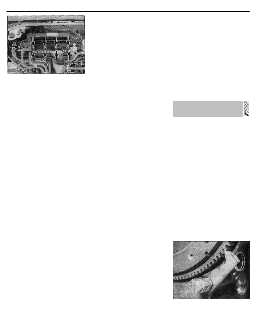
3 To prevent crankshaft turning whilst the
pulley retaining bolt is being slackened, select
top gear and have an assistant apply the
brakes firmly. If the engine has been removed
from the vehicle, lock the flywheel ring gear
using the arrangement shown (see
illustration). Do not attempt to lock the pulley
by inserting a bolt/drill through the pulley
timing hole.
4 Unscrew the retaining bolt and washer,
then slide the pulley off the end of the
5.3 Use a fabricated tool like this one to
lock the flywheel ring gear and prevent
crankshaft rotation
5 Crankshaft pulley -
removal and refitting
XU series engine in-car engine repair procedures 2B•7
crankshaft. If the pulley locating roll pin or
Woodruff key (as applicable) is a loose fit,
remove it and store it with the pulley for safe-
keeping.
Refitting
1998 cc 16-valve models
5 Ensure that the locating roll pin is in
position in the crankshaft. Offer up the pulley,
ensuring that it is the correct way around.
Locate the pulley on the roll pin, then refit the
retaining bolts and tighten them to the
specified torque. If necessary, prevent the
pulley from rotating as described in paragraph
3.
6 Refit and tension the auxiliary drivebelt as
described in Chapter 1.
All other models
7 Ensure that the Woodruff key is correctly
located in its crankshaft groove, or that the
roll pin is in position (as applicable). Refit the
pulley to the end of the crankshaft, aligning its
locating groove or hole with the Woodruff key
orpin.
8 Thoroughly clean the threads of the pulley
retaining bolt, then apply a coat of locking
compound to the bolt threads. Citroen
recommend the use of Frenbloc E6 (available
from your Citroen dealer); in the absence of
this, any good-quality locking compound may
be used.
9 Refit the crankshaft pulley retaining bolt
and washer. Tighten the bolt to the specified
torque, preventing the crankshaft from turning
using the method employed on removal.
10 Refit and tension the auxiliary drivebelt as
described in Chapter 1.
6 Timing belt covers
removal and refitting
1580 cc and 1905 cc models
Upper cover
1 Release the retaining clips, and free the fuel
hoses from the top of the cover.
2 Undo the two cover retaining bolts (situated
at the base of the cover), and remove the
cover from the engine compartment.
Centre cover - early (pre-1992)
models with a semi-automatic belt
tensioner
3 Slacken and remove the four cover
retaining nuts and bolts (two directly below
the mounting bracket, and two at the base of
the cover), then manoeuvre the cover
upwards out of the engine compartment.
Centre cover - later (1992-on) models
with a manually-adjusted belt
tensioner pulley
4 Slacken and remove the two cover retaining
bolts (located directly beneath the mounting
bracket). Move the cover upwards to free it
from the two locating pins situated at the base
of the cover, and remove it from the engine
compartment.
Lower cover
5 Remove the crankshaft pulley as described
in Section 5?
6 Remove the centre cover as described
above.
7 On early models, undo the three lower
cover retaining bolts and remove the cover
from the engine.
8 On later models, undo the two cover
retaining bolts and remove the cover from the
engine.
Lower (inner) cover - early (pre-1992)
models with a semi-automatic belt
tensioner
9 Remove the timing belt as described in
Section 7.
10 Slacken and remove the remaining bolts,
noting their correct fitted positions, and
remove the cover from the end of the cylinder
block.
1761 cc models
Upper cover
11 Proceed as described in paragraphs 1
and 2.
Centre cover
12 Proceed as described in paragraph 4.
Lower cover
13 Remove the crankshaft pulley as
described in Section 5.
14 Remove the centre cover as described in
paragraph 4.
15 Undo the two cover retaining bolts, and
remove the cover from the engine.
1998 cc 8-valve models
Upper cover
16 Release the retaining clip, and free the
fuel hoses from the top of the timing belt
cover.
17 Slacken and remove the two cover
retaining bolts, then lift the upper cover
upwards and out of the engine compartment.
Lower cover
18 Remove the crankshaft pulley as
described in Section 5.
19 Slacken and remove the three retaining
bolts, then remove the lower timing belt cover
from the engine.
1998 cc 16-valve models
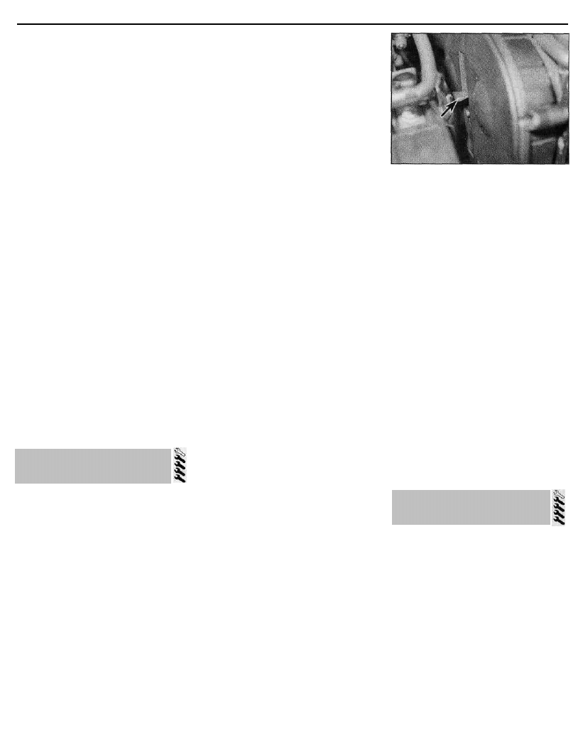
Upper (outer) cover
20 Undo the two upper retaining bolts
securing the outer cover to the inner cover.
Slide the cover retaining clip upwards to
release it from its fasteners (see illustration).
21 Ease the outer cover away from the
engine. Lift it upwards, freeing it from its
locating bolts at the base of the cover, and
out of the engine compartment.
6.20 Timing belt upper (outer) cover
retaining clip (arrowed) -1998 cc 16-valve
models
Lower cover
22 Remove the crankshaft pulley as
described in Section 5.
23 Remove the upper (outer) cover as
described above.
24 Slacken and remove the two upper cover
lower locating bolts, along with their spacers.
Undo the two lower cover retaining bolts, and
remove the cover from the engine.
Upper (inner) cover
25 Remove the timing belt as described in
Section 7.
26 Remove both camshaft sprockets as
described in Section 8.
27 Undo the six bolts securing the cover to
the side of the cylinder head, and remove the
cover from the engine.
Refitting
28 Refitting is a reversal of the relevant
removal procedure, ensuring that each cover
section is correctly located, and that the cover
retaining nuts and/or bolts are securely
tightened (to the specified torque, where
given).
7 Timing belt - general
information, removal and refitting.
General information
1 The timing belt drives the camshaft(s) and
coolant pump from a toothed sprocket on the
front of the crankshaft. If the belt breaks or
slips in service, the pistons are likely to hit the
valve heads, resulting in extensive (and
expensive) damage.
2 The timing belt should be renewed at the
specified intervals (see Chapter 1), or earlier if
it is contaminated with oil, or if it is at all noisy
in operation (a "scraping" noise due to uneven
wear).
3 If the timing belt is being removed, it is a
wise precaution to check the condition of the
coolant pump at the same time (check for
signs of coolant leakage). This may avoid the
need to remove the timing belt again at a later
stage, should the coolant pump fail.
2B•8 XU series engine in-car engine repair procedures
7.7 On early 1580 cc and 1905 cc models,
slacken the tensioner assembly retaining
n u t s . . .
Removal
Early (pre-1992) 1580 cc and 1905 cc
models with a semi-automatic belt
tensioner
4 Disconnect the battery negative terminal.
5 Align the engine assembly/valve timing
holes as described in Section 3, and lock the
camshaft sprocket and crankshaft pulley in
position. Do not attempt to rotate the engine
whilst the pins are in position.
6 Remove the centre and lower timing belt
covers as described in Section 6.
7 Slacken (but do not remove) the two nuts
securing the tensioner assembly to the end of
the cylinder block (see illustration). Loosen
the tensioner cam spindle locknut, located on
the rear of cylinder block flange.
8 Using a suitable open-ended spanner on
the square-section end of the tensioner cam
spindle, rotate the cam until the tensioner
spring is fully compressed and the belt
tension is relieved (see illustration). Hold the
cam in this position, and securely tighten the
locknut.
9 Place a jack beneath the engine, with a
block of wood on the jack head. Raise the jack
until it is supporting the weight of the engine.
10 Slacken and remove the three nuts
securing the engine/transmission right-hand
mounting bracket to the engine bracket.
Remove the single nut securing the bracket to
the mounting rubber, and lift off the bracket.
Undo the three bolts securing the engine
bracket to the end of the cylinder head/block,
and remove the bracket.
11 If the timing belt is to be re-used, use
white paint or chalk to mark the direction of
rotation on the belt (if markings do not already
exist), then slip the belt off the sprockets.
Note that the crankshaft must not be rotated
whilst the belt is removed.
12 Check the timing belt carefully for any
signs of uneven wear, splitting, or oil
contamination. Pay particular attention to the
roots of the teeth. Renew it if there is the
slightest doubt about its condition. If the
engine is undergoing an overhaul, and has
covered more than 24 000 miles (40 000 km)
7.8 . . . and the spindle locknut, then
release the belt tension by turning the
tensioner cam spindle using an open-
ended spanner
with the existing belt fitted, renew the belt as a
matter of course, regardless of its apparent
condition. The cost of a new belt is nothing
compared with the cost of repairs, should the
belt break in service. If signs of oil
contamination are found, trace the source of
the oil leak and rectify it. Wash down the
engine timing belt area and all related
components, to remove all traces of oil.
Later (1992-on) 1580 cc and 1905 cc
models with a manually-adjusted belt
tensioner pulley, and all 1761 cc and
1998 cc 8-valve models
13 Disconnect the battery negative terminal.
14 Align the engine assembly/valve timing
holes as described in Section 3, and lock the
camshaft sprocket and crankshaft pulley in
position. Do not attempt to rotate the engine
whilst the pins are in position.
15 Remove the centre and/or lower timing
belt cover(s) as described in Section 6 (as
applicable).
16 Loosen the timing belt tensioner pulley
retaining bolt. Pivot the pulley in a clockwise
direction, using a suitable square-section key
fitted to the hole in the pulley hub, then
securely retighten the retaining bolt.
17 On 1580 cc, 1761 cc and 1905 cc models,
dismantle the engine right-hand mounting as
described above in paragraphs 9 and 10.
18 On all models, remove and inspect the
timing belt as described in paragraphs 11
and 12.
1998 cc 16-valve models
19 Disconnect the battery negative terminal.
20 Align the engine assembly/valve timing
holes as described in Section 3, and lock the
camshaft sprockets and crankshaft pulley in
position. Do not attempt to rotate the engine
whilst the pins are in position.
21 Remove the timing belt lower cover as
described in Section 6.
22 Loosen the timing belt rear tensioner
pulley retaining bolt. Pivot the pulley in a
clockwise direction, using a suitable square-
section key fitted to the hole in the pulley hub,
then securely retighten the retaining bolt (see
illustration).
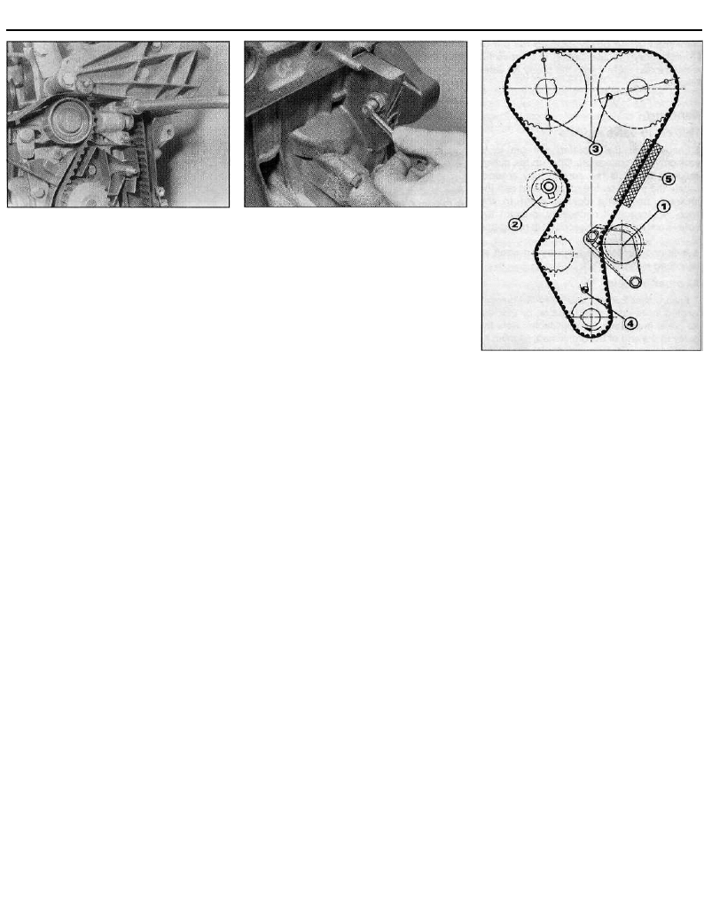
7.22 Timing belt arrangement - 1998 cc
16-valve models
1 Front tensioner assembly
2 Rear tensioner pulley
3 Camshaft sprocket timing holes
4 Crankshaft pulley timing hole
5 Belt tension measuring area (using Citroen
special tool)
23 Loosen the two front tensioner assembly
retaining bolts. Move the tensioner pulley
away from the belt, using the same square-
section key on the pulley backplate.
24 Check that the camshaft sprocket and
crankshaft locking pins are still in position,
then remove and inspect the timing belt as
described in paragraphs 11 and 12.
Refitting
Early (pre-1992) 1580 cc and 1905 cc
models with a semi-automatic belt
tensioner
25 Before refitting, thoroughly clean the
timing belt sprockets. Check that the
tensioner pulley rotates freely, without any
sign of roughness. If necessary, renew the
tensioner pulley as described in Section 8.
26 Ensure that the camshaft sprocket locking
pin is still in position. Temporarily refit the
crankshaft pulley, and insert the locking pin
through the pulley timing hole to ensure that
the crankshaft is still correctly positioned.
27 Remove the crankshaft pulley. Manoeuvre
the timing belt into position, ensuring that any
arrows on the belt are pointing in the direction
of rotation (clockwise when viewed from the
right-hand end of the engine).
28 Do not twist the timing belt sharply while
refitting it. Fit the belt over the crankshaft and
camshaft sprockets. Ensure that the belt
"front run" is taut - ie, any slack should be on
the tensioner pulley side of the belt. Fit the

XU series engine in-car engine repair procedures 2B•9
belt over the water pump sprocket and
tensioner pulley. Ensure that the belt teeth are
seated centrally in the sprockets.
29 Slacken the tensioner cam spindle
focknut, and check that the tensioner pulley is
forced against the timing belt by spring
pressure.
30 Refit the crankshaft pulley, tightening its
retaining bolt by hand only.
31 Rotate the crankshaft through at least two
complete rotations in a clockwise direction
(viewed from the right-hand end of the
engine). Realign the camshaft and crankshaft
engine assembly/valve timing holes (see
Section 3). Do not at any time rotate the
crankshaft anti-clockwise. Both camshaft and
crankshaft timing holes should be aligned so
that the locking pins can be easily inserted.
This indicates that the valve timing is correct.
32 If the timing holes are not correctly
positioned, release the tensioner assembly as
described in paragraph 8, and disengage the
belt from the camshaft sprocket. Rotate the
camshaft and crankshaft slightly as required
until both locking pins are in position.
Relocate the timing belt on the camshaft
sprocket. Ensure that the belt "front run" is
taut - ie, that any slack is on the tensioner
pulley side of the belt. Slacken the tensioner
tocknut, then remove the locking pins and
repeat the procedure described in para-
graph 31.
33 Once both timing holes are correctly
aligned, tighten the two tensioner assembly
retaining nuts to the specified torque. Tighten
the tensioner cam spindle locknut to its
specified torque.
34 With the belt correctly installed and
tensioned, refit the engine bracket to the side
of the cylinder head/block, and securely
tighten its retaining bolts. Refit the right-hand
mounting bracket, and tighten its retaining
nuts to the specified torque. The jack can then
be removed from underneath the engine.
35 Remove the crankshaft pulley, then refit
the timing belt covers as described in Section
6.
36 Install the crankshaft pulley as described
in Section 5, and reconnect the battery
negative terminal.
Later (1992-on) 1580 cc and 1905 cc
models with a manually-adjusted belt
tensioner pulley, and all 1761 cc and
1998 cc 8-valve models
Note: Citroen specify the use of a special
electronic tool (SEEM belt tension measuring
tool) to correctly set the timing belt tension. If
this equipment is not available, an
approximate setting can be achieved using
the method described below. If this method is
used, however, the belt tension must be
checked using the special electronic tool at
the earliest possible opportunity. Do not drive
the vehicle over large distances, or use high
engine speeds, until the belt tension is known
to be correct. Refer to a Citroen dealer for
advice.
37 Install the timing belt as described above
in paragraphs 25 to 28.
38 Loosen the tensloner pulley retaining bolt.
Using the square-section key, pivot the pulley
anti-clockwise to remove all free play from the
timing belt.
39 If the special belt tension measuring
equipment is available, it should be fitted to
the "front run" of the timing belt. The tensioner
roller should be adjusted so that the initial belt
tension is 16 ± 2 units on 1998 cc 8-valve
models, and 30 ± 2 units on all other models.
40 Tighten the pulley retaining bolt to the
specified torque. Refit the crankshaft pulley
again, tightening its retaining bolt by hand
only.
41 Carry out the operations described in
paragraph 31 (and where necessary,
paragraph 32, ignoring the information about
the tensioner) to ensure that both timing holes
are correctly aligned and the valve timing is
correct.
42 If the tension is being set without using
the special measuring tool, proceed as
follows. Check that, under moderate pressure
from the thumb and forefinger, the belt can
just be twisted through 90° at the mid-point of
the "front run" of the belt. Note that this
method is only an initial setting, and the belt
tension must checked at the earliest available
opportunity using the special measuring tool.
Failure to do so could lead to the belt
breaking (through over-tightening) or slipping
(through slackness), resulting in serious
engine damage. If necessary, readjust the
tensioner pulley position as required. Tighten
its retaining bolt to the specified torque on
completion.
43 If the special measuring tool is being
used, the belt tension on the "front run" of the
belt on all models should be 44 ± 2 units.
Readjust the tensioner pulley position as
required, then retighten the retaining bolt to
the specified torque. Rotate the crankshaft
through a further two rotations clockwise, and
recheck the tension. Repeat this procedure as
necessary until the correct tension reading is
obtained after rotating the crankshaft.
44 With the belt tension correctly set, on
1580 cc, 1761 cc and 1905 cc models, refit
the engine bracket to the side of the cylinder
head/block, and securely tighten its retaining
bolts. Refit the right-hand engine mounting
bracket, and tighten its retaining nuts to the
specified torque. The jack can then be
removed from underneath the engine.
45 On all models, remove the crankshaft
pulley, then refit the timing belt cover(s) as
described in Section 6.
46 Refit the crankshaft pulley as described in
Section 5, and reconnect the battery negative
terminal.
1998 cc 16-valve models
Note: Citroen specify the use of a special
electronic tool (SEEM belt tension measuring
tool) to correctly set the timing belt tension. If
this equipment is not available, an approxi-
mate setting can be achieved using the
method described below. If this method is
used, however, the tension must be checked
using the special electronic tool at the earliest
possible opportunity. Do not drive the vehicle
over large distances, or use high engine
speeds, until the belt tension is known to be
correct. Refer to a Citroen dealer for advice.
47 Before refitting, thoroughly clean the
timing belt sprockets. Check that each
tensioner pulley rotates freely, without any
sign of roughness. If necessary, renew the
tensioner pulley(s) as described in Section 8.
48 Ensure that the camshaft and crankshaft
sprocket locking pins are still in position.
Slacken both tensioner mounting bolts so that
they are free to pivot easily.
49 Manoeuvre the timing belt into position,
ensuring that any arrows on the belt are
pointing in the direction of rotation (clockwise
when viewed from the right-hand end of the
engine).
50 Note that there are also timing marks on
the belt, in the form of yellow lines, to ensure it
is correctly positioned on both camshaft
sprockets and the crankshaft sprocket. The
two single-line timing marks should be aligned
with the timing dot (directly opposite the
sprocket timing hole) on each camshaft
sprocket. The double-line timing mark should
be aligned with the crankshaft sprocket,
where it will be directly opposite the sprocket
Woodruff key slot. Citroen state that the use
of these timing marks is optional, but they are
useful in helping to ensure that the valve
timing is correctly set at the first attempt.
51 With the three locking pins in position,
move both the front and rear tensioner pulleys
towards the timing belt until both pulleys are
contacting the belt. Securely tighten the rear
tensioner retaining bolt.
52 If the tension is being set without the use
of the special measuring tool, proceed as
follows. Using the square-section key fitted to
the hole in the tensioner backplate, move the
front tensioner pulley against the belt until all
free play is removed from the belt. Hold the
tensioner in this position, and tighten the
pulley retaining bolts to the specified torque.
53 If the special belt tension measuring
equipment is available, it should be fitted to
the "front run" of the timing belt, between the
front tensioner and the camshaft sprocket.
Move the tensioner pulley backplate so that
the belt is initially over-tensioned to a setting
of 45 units, then back the tensioner off until
the belt terision is 22 ± 2 units. Hold the
backplate in this position, and tighten both the
tensioner pulley retaining bolts to the
specified torque.
54 Slacken the rear tensioner pulley retaining
bolt. Using the square-section key, pivot the
pulley anti-clockwise until all free play is
removed from the belt. If the belt tension
measuring equipment is being used, set the
tensioner pulley so that the belt tension on the
"front run" is 32 ± 2 units. Hold the tensioner

2B•10 XU series engine in-car engine repair procedures
in position, and tighten its retaining bolt to the
specified torque setting.
55 Remove the locking pins from the
camshaft and crankshaft sprockets and,
where fitted, the tensioning measuring device
from the belt.
56 Rotate the crankshaft through at least two
complete rotations in a clockwise direction
(viewed from the right-hand end of the
engine). Realign the camshaft and crankshaft
engine assembly/valve timing holes (see
Section 3). Do not at any time rotate the
crankshaft anti-clockwise. Both camshaft
timing holes and the crankshaft timing hole
should be correctly positioned so that the
locking pins can be easily inserted, indicating
that the valve timing is correct.
57 If the timing holes are not correctly
positioned, slacken the tensioner assembly
retaining bolts, and disengage the belt from
the camshaft sprockets. Rotate the camshafts
and crankshaft slightly as required until all
locking pins are in position, then relocate the
timing belt on the camshaft sprocket. Ensure
that the belt "top run" and "front run" are taut
- ie, ensure that any slack is on the rear
tensioner pulley and water pump side of the
belt. Repeat the tensioning procedure
described in paragraphs 51 to 56 until the
valve timing is correct.
58 Once the valve timing is correctly set,
remove the locking pins and recheck the belt
tension.
59 If the tension is being set without the
special measuring tool, proceed as follows.
Check that, under moderate pressure from
the thumb and forefinger, the belt can just be
twisted through 45°, at the mid-point between
the camshaft sprocket and tensioner pulley on
the "front run" of the belt. Note that this
method is only an initial setting, and the belt
tension must checked at the earliest available
opportunity using the special measuring tool.
Failure to do so could lead to the belt
breaking (through over-tightening) or slipping
(through slackness), resulting in serious
engine damage. If necessary, readjust the rear
tensioner pulley position as required, and
tighten its retaining bolt to the specified
torque.
60 If the special measuring tool is being
used, the final belt tension on the "front run"
of the belt, between the camshaft sprocket
and tensioner pulley, should be 53 ± 2 units.
Readjust the rear tensioner pulley position as
required, then retighten the retaining bolt to
the specified torque. Rotate the crankshaft
through a further two rotations clockwise, and
recheck the tension. Repeat this procedure as
necessary, until the correct tension reading is
obtained after the crankshaft has been
rotated.
61 Once the belt tension is correctly set, refit
the timing belt covers as described in Sec-
tion 6. Refit the crankshaft pulley as described
in Section 5, and reconnect the battery
negative terminal
8 Timing belt tensioner and
sprockets - removal,
inspection and refitting
Note: This Section describes the removal and
refitting of the components concerned as
individual operations - if more than one is to
be removed at the same time, start by
removing the timing belt as described in
Section 7; remove the actual component as
described below, ignoring the preliminary
dismantling steps.
Removal
1 Disconnect the battery negative lead.
2 Align the engine assembly/valve timing
holes as described in Section 3, locking the
camshaft sprocket(s) and the crankshaft
pulley in position, and proceed as described
under the relevant sub-heading. Do not
attempt to rotate the engine whilst the pins
are in position.
Camshaft sprocket - early (pre-1992)
1580 cc and 1905 cc models with a
semi-automatic belt tensioner
3 Remove the centre timing belt cover as
described in Section 6.
4 Slacken (but do not remove) the two nuts
securing the tensioner assembly to the end of
the cylinder block. Loosen the tensioner cam
spindle locknut, located on the rear of cylinder
block flange.
5 Using a suitable open-ended spanner on
the square-section end of the tensioner cam
spindle, rotate the cam until the tensioner
spring is fully compressed and the belt
tension is relieved. Hold the cam in this
position, and securely tighten the locknut.
6 Remove the locking pin from the camshaft
sprocket. Disengage the timing belt from the
sprocket and position it clear, taking care not
to bend or twist the belt sharply.
7 Slacken the camshaft sprocket retaining
bolt and remove it, along with its washer. To
prevent the camshaft rotating as the bolt is
slackened, a sprocket holding tool will be
required. Do not attempt to use the sprocket
locking pin to prevent the sprocket from
rotating whilst the bolt is slackened
8 With the retaining bolt removed, slide the
sprocket off the end of the camshaft. If the
locating peg is a loose fit in the rear of the
sprocket, remove it for safe-keeping. Examine
the camshaft oil seal for signs of oil leakage
and, if necessary, renew it as described in
Section 9.
Camshaft sprocket - later (1992-on)
1580 cc and 1905 cc models with a
manually-adjusted belt tensioner
pulley, and all 1761 cc and 1998 cc
8-valve models
9 On all except 1998 cc 8-valve models,
remove the centre timing belt cover as
described in Section 6.
10 Loosen the timing belt tensioner pulley
retaining bolt. Rotate the pulley in a clockwise
direction, using a suitable square-section key
fitted to the hole in the pulley hub, then
retighten the retaining bolt.
11 Remove the camshaft sprocket as
described above in paragraphs 6 to 8.
Camshaft sprocket(s) -1998 cc
16-valve models
12 Loosen the timing belt rear tensioner
pulley retaining bolt. Pivot the pulley in a
clockwise direction, using a suitable square-
section key fitted to the hole in the pulley hub,
then securely retighten the retaining bolt.
13 Loosen the two front tensioner assembly
retaining bolts. Move the tensioner pulley
away from the belt, using the same square-
section key on the pulley backplate.
14 Remove the camshaft sprocket retaining
bolt as described above in paragraphs 6 and 7.
15 Slide the sprocket off the end of the
camshaft. If the Woodruff key is a loose fit in
the camshaft, remove it and store it with the
sprocket for safe-keeping. Examine the
camshaft oil seal for signs of oil leakage and, if
necessary, renew it as described in Section 9.
Crankshaft sprocket -1580 cc,
1761 cc, 1905 cc and 1998 cc 8-valve
models
16 Remove the centre and/or lower timing
belt cover(s) (as applicable) as described in
Section 6.
17 On early (pre-1992) 1580 cc and 1905 cc
models with a semi-automatic belt tensioner,
release the timing belt tensioner as described
above in paragraphs 4 and 5.
18 On later (1992-on) 1580 cc and 1905 cc
models with a manually-adjusted belt
tensioner pulley, and all 1761 cc and 1998 cc
8-valve models, release the timing belt
tensioner as described in paragraph 10.
19 Disengage the timing belt from the
crankshaft sprocket, and slide the sprocket
off the end of the crankshaft. Remove the
Woodruff key from the crankshaft, and store it
with the sprocket for safe-keeping. Where
necessary, also slide the flanged spacer
(where fitted) off the end of the crankshaft.
20 Examine the crankshaft oil seal for signs
of oil leakage and, if necessary, renew it as
described in Section 16.
Crankshaft sprocket -1998 cc
16-valve models
21 Remove the lower timing belt cover as
described in Section 6.
To prevent the camshaft
sprocket from rotating, use
two lengths of steel strip (one
long, the other short), and
three nuts and bolts; one nut and holt
forms the pivot of a forked tool, with
the remaining two nuts and bolts at the
tips of the "forks" to engage with the
sprocket spokes as shown in
illustration 8.39.
XU series engine in-car engine repair procedures 2B•11
22 Release the timing belt tensioners as
described above in paragraphs 12 and 13.
Disengage the timing belt from the crankshaft
sprocket, and remove the locking pin.
23 To prevent the crankshaft turning whilst
the sprocket retaining bolt is being slackened,
select top gear, and have an assistant apply
the brakes firmly. If the engine has been
removed from the vehicle, lock the flywheel
ring gear using the arrangement shown in
illustration 5.3 (Section 5). Do not be tempted
to use the locking pin to prevent the
crankshaft from rotating.
24 Unscrew the retaining bolt and washer,
then slide the sprocket off the end of the
crankshaft. If the Woodruff key is a loose fit in
the crankshaft, remove it and store it with the
sprocket for safe-keeping.
25 Where necessary, slide the flanged
spacer (where fitted) off the end of the
crankshaft.
26 Examine the crankshaft oil seal for signs
of oil leakage and, if necessary, renew it as
described in Section 16.
Tensioner assembly - early (pre-1992)
1580 cc and 1905 cc models with a
semi-automatic belt tensioner
27 Remove the centre timing belt cover as
described in Section 6.
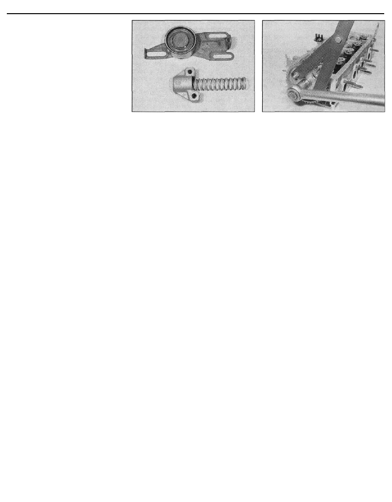
28 Slacken and remove the two nuts and
washers securing the tensioner assembly to
the end of the cylinder block. Carefully ease
the spring cover off its studs, taking care not
to allow the spring to fly out as the cover is
withdrawn. Remove the spring and cover from
the engine (see illustration).
29 Slacken and remove the tensioner cam
spindle Iocknut and washer, located on the
rear of cylinder block flange, and withdraw the
cam spindle.
30 The tensioner pulley and backplate
assembly can then be manoeuvred out from
behind the timing belt.
Tensioner pulley - later (1992-on)
1580 cc and 1905 cc models with a
manually-adjusted belt tensioner
pulley, and all 1761 cc and 1998 cc
8-valve models
31 On all except 1998 cc 8-valve models,
remove the centre timing belt cover as
described in Section 6.
32 Slacken and remove the timing belt
tensioner pulley retaining bolt, and slide the
pulley off its mounting stud. Examine the
mounting stud for signs of damage and if
necessary, renew it.
Tensioner pulleys -1998 cc 16-valve
models
33 The rear tensioner pulley is removed as
described above in paragraph 32.
34 To remove the front tensioner pulley,
slacken and remove the two bolts securing
the pulley backplate to the cylinder block, and
remove the assembly from the engine unit.
8.28 Timing belt tensioner assembly
components - early 1580 cc and 1905 cc
models
Inspection
35 Clean the camshaft/crankshaft sprockets
thoroughly, and renew any that show signs of
wear, damage or cracks.
36 Clean the tensioner assembly, but do not
use any strong solvent which may enter the
pulley bearing. Check that the pulley rotates
freely on the backplate, with no sign of
stiffness or free play. Renew the assembly if
there is any doubt about its condition, or if
there are any obvious signs of wear or
damage.
37 On early 1580 cc and 1905 cc models, the
tensioner spring should also be carefully
checked, as its condition is critical for the
correct tensioning of the timing belt. The only
way of checking the spring tension is to
compare it with a new one; if there is any
doubt as to its condition, the spring should be
renewed.
Refitting
Camshaft sprocket - early (pre-1992)
1580 cc and 1905 cc models with a
semi-automatic belt tensioner
38 Refit the locating peg (where removed) to
the rear of the sprocket. Locate the sprocket
on the end of the camshaft, ensuring that the
locating peg is correctly engaged with the
cutout in the camshaft end.
39 Refit the sprocket retaining bolt and
washer, and tighten it to the specified torque.
Retain the sprocket with the tool used on
removal (see illustration).
40 Realign the hole in the camshaft sprocket
with the corresponding hole in the cylinder
head, and refit the locking pin. Check that the
crankshaft pulley locking pin is still in position.
41 Refit the timing belt to the camshaft
sprocket. Ensure that the "front run" of the
belt is taut - ie, that any slack is on the
tensioner pulley side of the belt. Do not twist
the belt sharply while refitting it, and ensure
that the belt teeth are seated centrally in the
sprockets.
42 Release the tensioner cam spindle
Iocknut, and check that the tensioner pulley is
forced against the timing belt under spring
pressure.
8.39 Using a home-made tool to retaining
the camshaft sprocket whilst the sprocket
retaining bolt is tightened (TU engine
shown)
43 Tension the timing belt as described in
paragraphs 31 to 33 of Section 7.
44 With the belt correctly tensioned, and the
tensioner retaining nuts and Iocknut tightened
to the specified torque setting, refit the timing
belt covers as described in Section 6.
Reconnect the battery on completion.
Camshaft sprocket - later (1992-on)
1580 cc and 1905 cc models with a
manually-adjusted belt tensioner
pulley, and all 1761 cc and 1998 cc
8-valve models
45 Refit the camshaft sprocket as described
above in paragraphs 38 to 41.
46 With the timing belt correctly engaged on
the sprockets, tension the belt as described in
paragraphs 38 to 43 of Section 7.
47 Once the belt is correctly tensioned, refit
the timing belt covers as described in Section 6.
Camshaft sprocket(s) -1998 cc
16-valve models
48 Refit the Woodruff key to its slot in the
camshaft end. Slide on the sprocket, aligning
its slot with the Woodruff key.
49 Refit the sprocket retaining bolt and
washer. Tighten the bolt to the specified
torque, whilst retaining the sprocket with the
tool used on removal.
50 Realign the hole in the camshaft sprocket
with the corresponding hole in the cylinder
head, and refit the locking pin.
51 Relocate the timing belt on the camshaft
sprocket(s), and tension the timing belt as
described in paragraphs 50 to 60 of Section 7.
52 Once the belt is correctly tensioned, refit
the timing belt cover as described in Section 6.
Crankshaft sprocket -1580 cc,
1761 cc, 1905 cc and 1998 cc 8-valve
models
53 Slide on the flanged spacer (where fitted),
and refit the Woodruff key to its slot in the
crankshaft end.
54 Slide on the crankshaft sprocket, aligning
its slot with the Woodruff key.
55 Ensure that the camshaft sprocket locking
pin is still in position. Temporarily refit the
crankshaft pulley, and insert the locking pin

2B•12 XU series engine in-car engine repair procedures
through the pulley timing hole, to ensure that
the crankshaft is still correctly positioned.
56 Remove the crankshaft pulley. Engage the
timing belt with the crankshaft sprocket.
Ensure that the belt "front run" is taut - ie, that
any slack is on the tensioner pulley side of the
belt. Fit the belt over the water pump sprocket
and tensioner pulley. Do not twist the belt
sharply while refitting it, and ensure that the
belt. teeth are seated centrally in the
sprockets.
57 On early (pre-1992) 1580 cc and 1905 cc
models with a semi-automatic tensioner,
release the tensioner cam spindle locknut,
checking that the tensioner pulley is forced
against the timing belt under spring pressure.
Tension the timing belt as described in
paragraphs 30 to 33 of Section 7.
58 On later (1992-on) 1580 cc and 1905 cc
models with a manually-adjusted belt
tensioner pulley, and all 1761 cc and 1998 cc
8-valve models, tension the timing belt as
described in 38 to 43 of Section 7.
59 On all models, remove the crankshaft
pulley, then refit the timing belt cover(s) as
described in Section 6.
60 Refit the crankshaft pulley as described in
Section 5, and reconnect the battery negative
terminal.
Crankshaft sprocket -1998 cc
16-valve models
61 Slide on the flanged spacer (where fitted),
and refit the Woodruff key to its slot in the
crankshaft end.
62 Slide on the crankshaft sprocket, aligning
its slot with the Woodruff key.
63 Thoroughly clean the threads of the
sprocket retaining bolt, then apply a coat of
locking compound to the threads of the bolt.
Citroen recommend the use of Frenbloc E6
(available from your Citroen dealer); in the
absence of this, any good-quality locking
compound may be used.
64 Refit the crankshaft sprocket retaining
bolt and washer. Tighten the bolt to the
specified torque, whilst preventing crankshaft
rotation using the method employed on
removal.
65 Refit the locking pin to the crankshaft
sprocket, and check that both the camshaft
sprocket locking pins are still in position.
66 Relocate the timing belt on the crankshaft
sprocket, and tension the timing belt as
described in paragraphs 50 to 60 of Section 7.
67 Once the belt is correctly tensioned, refit
the timing belt cover as described in Section 6.
Tensioner assembly - early (pre-1992)
1580 cc and 1905 cc models with a
semi-automatic belt tensioner
68 Manoeuvre the tensioner pulley and
backplate assembly into position behind the
timing belt, and locate it on the mounting studs.
69 Insert the tensioner cam spindle through
the backplate from the front of the block, and
refit its washer and locknut, tightening it by
hand only at this stage.
70 Fit the spring to the inside of the spring
cover. Compress the spring, and slide the
spring cover onto the two mounting studs,
ensuring that the spring end is correctly
located behind the backplate tang.
71 Refit the tensioner mounting nuts and
washers, tightening them by hand only. Check
that the tensioner is forced against the timing
belt by spring pressure, and is free to move
smoothly and easily.
72 Ensure that the "front run" of the belt is
taut - ie, that any slack is on the pulley side of
the belt. Check that the belt is centrally
located on all its sprockets, then release the
tensioner assembly and allow it to tension the
belt.
73 Tension the timing belt, and check the
valve timing as described in paragraphs 31 to
33 of Section 7.
74 With the belt correctly tensioned, and the
tensioner retaining nuts and locknut tightened
to the specified torque setting, refit the timing
belt covers as described in Section 6.
Reconnect the battery on completion.
Tensioner pulley - later (1992-on)
1580 cc and 1905 cc models with a
manually-adjusted belt tensioner
pulley, and all 1761 cc and 1998 cc
8-valve models
75 Refit the tensioner pulley to its mounting
stud, and fit the retaining bolt.
76 Ensure that the "front run" of the belt is
taut - ie, that any slack is on the pulley side of
the belt. Check that the belt is centrally
located on all its sprockets. Rotate the pulley
anti-clockwise to remove all free play from the
timing belt, and securely tighten the pulley
retaining nut.
77 Tension the belt as described in 38 to 43
of Section 7.
78 Once the belt is correctly tensioned, refit
the timing belt covers as described in Section 6.
Tensioner pulleys -1998 cc 16-valve
models
79 Refit the rear tensioner pulley to its
mounting stud, and fit the retaining bolt. Align
the front pulley backplate with its holes, and
refit both its retaining bolts. Tighten all
retaining bolts finger-tight only, so that both
tensioners are free to pivot.
80 Tension the timing belt as described in
paragraphs 51 to 60 of Section 7.
81 Once the belt is correctly tensioned, refit
the timing belt cover as described in Section 6.
Note: If the camshaft oil seal is to be renewed
with the timing belt still in place, check first
that the belt is free from oil contamination.
(Renew the belt as a matter of course if signs
of oil contamination are found; see Section 7.)
Cover the belt, to protect it from contami-
nation by oil while work is in progress. If the
timing belt is removed, ensure that all traces
of oil are removed from the area before the
belt is refitted.
1 Remove the camshaft sprocket(s) as
described in Section 8.
2 Punch or drill two small holes opposite
each other in the oil seal. Screw a self-tapping
screw into each, and pull on the screws with
pliers to extract the seal.
3 Clean the seal housing, and polish off any
burrs or raised edges, which may have
caused the seal to fail in the first place.
4 Lubricate the lips of the new seal with clean
engine oil, and drive it into position until it
seats on its locating shoulder. Use a suitable
tubular drift, such as a socket, which bears
only on the hard outer edge of the seal. Take
care not to damage the seal lips during fitting.
Note that the seal lips should face inwards.
5 Refit the camshaft sprockets) as described
in Section 8.
Removal
1 Disconnect the battery negative terminal,
and remove the cylinder head cover as
described in Section 4. Proceed as described
under the relevant sub-heading.
1998 cc 16-valve models
2 Remove the vacuum pump from the left-
hand end of the cylinder head, as described in
Chapter 9.
3 Remove both camshaft sprockets as
described in Section 8.
4 Undo the six bolts securing the inner timing
belt cover to the side of the cylinder head, and
remove the cover from the engine.
5 Carefully ease the oil supply pipe out from
the top of the camshaft bearing caps, and
remove it. Note the O-ring seals fitted to each
of the pipe unions.
6 The camshaft bearing caps should be
numbered 1 to 5, number 1 being at the
transmission end of the engine. If not, make
identification marks on the caps, using white
paint or a suitable marker pen.
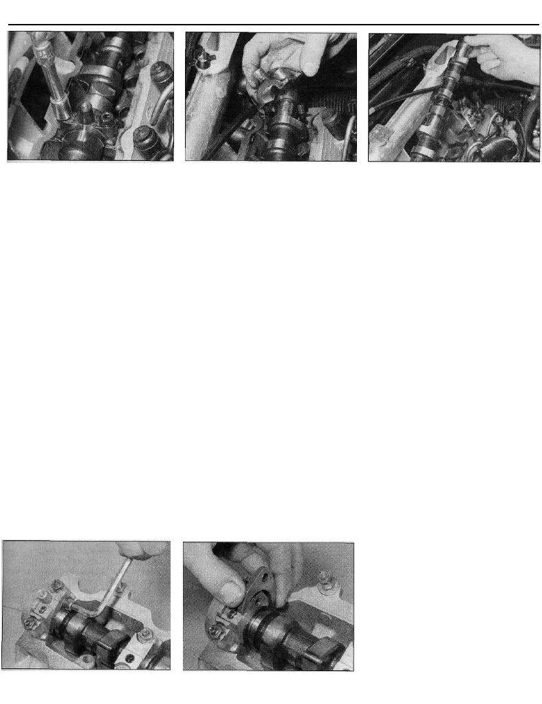
7 Working in the reverse of the sequence
shown in illustration 10.28, evenly and
progressively slacken the camshaft bearing
cap retaining screws by one turn at a time.
This will relieve the valve spring pressure on
the bearing caps gradually and evenly. Once
the pressure has been relieved, the bolts can
be fully unscrewed and removed.
8 Lift off the bearing caps, noting the correct
fitted location of the locating dowels. If the
dowels are a loose fit, remove them and store
them with the bearing caps for safe-keeping.
9 Lift the camshafts out of the cylinder head,
and slide the oil seals off the camshaft ends.
The inlet camshaft can be identified by the
braking system vacuum pump drive slot in its
left-hand end; therefore, there is no need to
mark the camshafts for identification.
10 Obtain sixteen small, clean plastic
9 Camshaft oil seal(s) - renewal
10 Camshaft(s) and followers -
removal, inspection and refitting
XU series engine in-car engine repair procedures 2B•13
10.17 Working as described in the text,
unscrew the retaining nuts . . .
containers, and number them 1 to 16. Using a
rubber sucker, withdraw each cam follower in
turn, invert it to prevent oil loss, and place it in
its respective container. The container should
then be filled with clean engine oil. Do not
interchange the cam followers, or the rate of
wear will be much-increased. Do not allow
them to lose oil, or the hydraulic tappet
mechanism will take a long time to refill with
oil on restarting the engine, resulting in
incorrect valve clearances.
All other models
11 Remove the camshaft sprocket as
described in Section 8.
12 On models with a distributor, remove the
distributor as described in Chapter 5.
13 On models with a static (distributorless)
ignition system, remove the ignition HT coil as
described in Chapter 5.
14 With the distributor or coil removed (as
applicable), slacken the upper bolt securing
the thermostat housing to the left-hand end of
the cylinder head. Remove the bolt, along with
its sealing washer. This is necessary since the
bolt screws into the left-hand (No 1) camshaft
bearing cap.
15 Carefully ease the oil supply pipe out from
the top of the camshaft bearing caps, and
remove it. Note the O-ring seals fitted to each
of the pipe unions.
16 The camshaft bearing caps should be
numbered 1 to 5, number 1 being at the
transmission end of the engine. If not, make
identification marks on the caps, using white
10.18 . . . and remove the camshaft
bearing caps . . .
paint or a suitable marker pen. Also mark
each cap in some way to indicate its correct
fitted orientation. This will avoid the possibility
of installing the caps the wrong way around
on refitting.
17 Evenly and progressively slacken the
camshaft bearing cap retaining nuts by one
turn at a time. This will relieve the valve spring
pressure on the bearing caps gradually and
evenly. Once the pressure has been relieved,
the nuts can be fully unscrewed and removed
(see illustration).
18 Note the correct fitted orientation of the
bearing caps, then remove them from cylinder
head (see illustration).
19 Lift the camshaft away from the cylinder
head, and slide the oil seal off the camshaft
end (see illustration).
20 Obtain eight small, clean plastic
containers, and number them 1 to 8;
alternatively, divide a larger container into eight
compartments. Using a rubber sucker,
withdraw each follower in turn, and place it in
its respective container. Do not interchange the
cam followers, or the rate of wear will be much-
increased. If necessary, also remove the shim
from the top of the valve stem, and store it with
its respective follower. Note that the shim may
stick to the inside of the follower as it is
withdrawn. If this happens, take care not to
allow it to drop out as the follower is removed.
Inspection
21 Examine the camshaft bearing surfaces
and cam lobes for signs of wear ridges and
10.24a On early 1580 cc and 1905 cc
models, slacken the retaining b o l t . . .
10.24b . . . and remove the camshaft
thrust fork from the bearing cap
10.19 . . . then lift the camshaft away from
the cylinder head
scoring. Renew the camshaft if any of these
conditions are apparent. Examine the
condition of the bearing surfaces, both on the
camshaft journals and in the cylinder
head/bearing caps. If the head bearing
surfaces are worn excessively, the cylinder
head will need to be renewed. If suitable
measuring equipment is available, camshaft
bearing journal wear can be checked by direct
measurement (where the necessary
specifications have been quoted by Citroen),
noting that No 1 journal is at the transmission
end of the head.
22 Examine the cam follower bearing
surfaces which contact the camshaft lobes for
wear ridges and scoring. Renew any follower
on which these conditions are apparent. If a
follower bearing surface is badly scored, also
examine the corresponding lobe on the
camshaft for wear, as it is likely that both will
be worn. Renew worn components as
necessary.
23 On 1998 cc 16-valve models, if the
engine's valve clearances have sounded
noisy, particularly if the noise persists after
initial start-up from cold, there is reason to
suspect a faulty hydraulic tappet mechanism.
Only a good mechanic experienced in these
engines can tell whether the noise level is
typical, or if renewal of one or more of the
tappets is warranted. If a faulty hydraulic
tappet is diagnosed and the engine's service
history is unknown, it is always worth trying
the effect of renewing the engine oil and filter
before going to the expense of renewing any
of the cam followers. Use only good-quality
engine oil of the recommended viscosity and
specification (Chapter 1). It is not possible to
overhaul the hydraulic tappet mechanism, so
if any tappet's operation is faulty, it must be
renewed.
24 On earlier 1580 cc and 1905 cc models,
inspect the camshaft thrust fork (fitted to the
side of No 5 camshaft bearing cap) for signs
of wear or scoring, and if necessary renew it
(see illustrations). The fork is retained by a
single bolt; on refitting, ensure that the bolt is
securely tightened. On later models, the thrust
fork is no longer fitted, and the camshaft
endfloat is controlled by the camshaft bearing
cap.
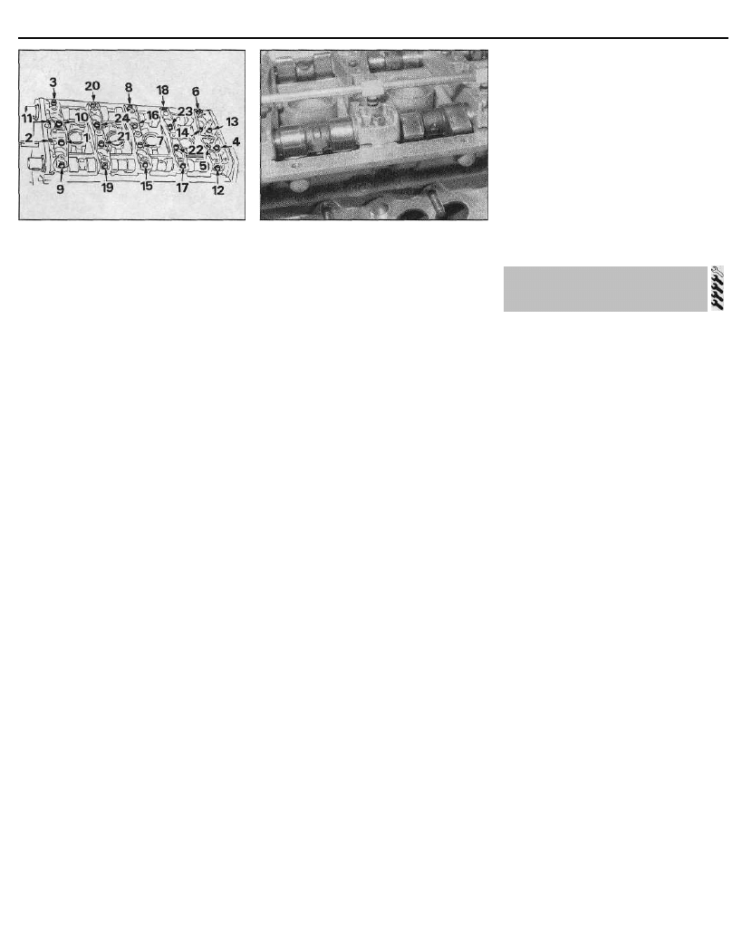
2B•14 XU series engine in-car engine repair procedures
10.28 Camshaft bearing cap bolt
tightening sequence -1998 cc 16-valve
models
Refitting
1998 cc 16-valve models
25 Liberally oil the cylinder head cam
follower bores and the followers. Note that, if
new followers are being fitted, they must be
charged with oil before installation by placing
them in a bath of clean engine oil and
"working" them. Carefully refit the followers to
the cylinder head, ensuring that each follower
is refitted to its original bore, where
applicable. Some care will be required to
enter the followers squarely into their bores.
26 Liberally oil the camshaft bearings and
lobes, then refit the camshafts to the cylinder
head. Temporarily refit the Woodruff keys and
sprockets to the end of each camshaft. Set
each camshaft so that its sprocket timing hole
is aligned with the corresponding cutout in the
cylinder head. Also ensure that the crankshaft
is still locked in position (see Section 3).
27 Ensure that the bearing cap locating
dowels are pressed firmly into their recesses.
Check that the mating surfaces are
completely clean, unmarked and free from oil.
Refit the bearing caps, using the identification
marks noted on removal to ensure that each is
installed correctly and in its original location.
28 Working in the sequence shown,
progressively tighten the camshaft bearing
cap bolts by one turn at a time, until the caps
touch the cylinder head evenly. Go round
again, working in the same sequence, and
tighten all the bolts to the specified torque
setting (see illustration). Work only as
described, to impose the pressure of the valve
springs gradually and evenly on the bearing
caps.
29 Examine the oil supply pipe union O-rings
for signs of damage or deterioration, and
renew as necessary. Check that the supply
pipe oil spray holes are clear, unblocking
them with a pin if necessary. Apply a smear of
clean engine oil to the O-rings. Ease the pipe
assembly into position in the top of the
bearing caps, taking great care not to
displace the O-rings (see illustration).
30 Refit the inner timing belt cover to the side
of the cylinder head, and tighten its retaining
bolts to the specified torque.
10.29 Take care not to displace the O-
rings when refitting the oil supply pipe to
the camshaft bearing caps
31 Fit two new camshaft oil seals using the
information given in Section 7, then refit the
camshaft sprockets as described in Section 8.
32 Refit the vacuum pump as described in
Chapter 9.
33 Refit the cylinder head cover as described
in Section 4, and reconnect the battery
negative terminal.
All other models
32 Where removed, refit each shim to the top
of its original valve stem. Do not interchange
the shims, as this will upset the valve
clearances (see Section 11).
33 Liberally oil the cylinder head cam
follower bores and the followers. Carefully
refit the followers to the cylinder head,
ensuring that each follower is refitted to its
original bore. Some care will be required to
enter the followers squarely into their bores.
34 Liberally oil the camshaft bearings and
lobes, then refit the camshaft to the cylinder
head. Temporarily refit the sprocket to the end
of the shaft, and position it so that the
sprocket timing hole is aligned with the
corresponding cutout in the cylinder head.
Also ensure that the crankshaft is still locked
in position (see Section 3).
35 Ensure that the bearing cap and head
mating surfaces are completely clean,
unmarked, and free from oil. Refit the bearing
caps, using the identification marks noted on
removal to ensure that each is installed
correctly and in its original location.
36 Evenly and progressively tighten the
camshaft bearing cap nuts by one turn at a
time until the caps touch the cylinder head.
Then go round again and tighten all the nuts
to the specified torque setting. Work only as
described, to impose the pressure of the valve
springs gradually and evenly on the bearing
caps.
37 Examine the oil supply pipe union O-rings
for signs of damage or deterioration, and
renew as necessary. Apply a smear of clean
engine oil to the O-rings. Ease the pipe into
position in the top of the bearing caps, taking
great care not to displace the O-rings.
38 Examine the sealing washer for signs of
damage or deterioration, and renew it if
necessary. Refit the upper retaining bolt to the
thermostat housing, tightening it to the
specified torque setting.
39 On models with a distributor, refit the
distributor as described in Chapter 5.
40 On models with a static (distributorless)
ignition system, refit the ignition HT coil as
described in Chapter 5.
41 Fit a new camshaft oil seal, using the
information given in Section 7, then refit the
camshaft sprocket as described in Section 8.
42 Refit the cylinder head cover as described
in Section 4, and reconnect the battery
negative terminal.
Checking
1998 cc 16-valve models
1 On 1998 cc 16-valve models, the valve
clearances are automatically adjusted by the
hydraulic tappet mechanism fitted to each
cam follower. Therefore it is not necessary, or
indeed possible, to check or adjust the valve
clearances manually. If the valve gear has
become noisy, a faulty tappet mechanism
should be suspected. Refer to paragraph 23
of Section 10 for further information.
All other models
2 On these models, the importance of having
the valve clearances correctly adjusted
cannot be overstressed, as they vitally affect
the performance of the engine. Checking
should not be regarded as a routine operation,
however. It should only be necessary when
the valve gear has become noisy, after engine
overhaul, or when trying to trace the cause of
power loss. The clearances are checked as
follows. The engine must be cold for the
check to be accurate.
3 Apply the handbrake, then jack up the front
of the car and support it on axle stands.
Remove the right-hand front roadwheel.
4 From underneath the front of the car, prise
out the two retaining clips, and remove the
plastic cover from the wing valance to gain
access to the crankshaft sprocket bolt. Where
necessary, unclip the coolant hoses from the
bracket to improve access further.
5 The engine can now be turned over using a
suitable socket and extension bar fitted to the
crankshaft pulley bolt.
6 Remove the cylinder head cover as
described in Section 4.
7 Draw the outline of the engine on a piece of
paper, numbering the cylinders 1 to 4, with
No 1 cylinder at the transmission end of the
engine. Show the position of each valve,
together with the specified valve clearance
(see paragraph 11). Above each valve, draw
two lines for noting (1) the actual clearance
11 Valve clearances -
checking and adjustment
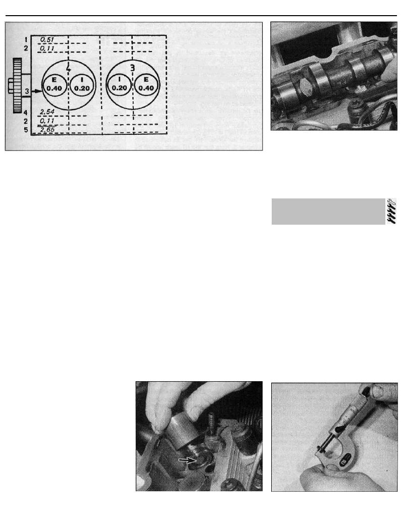
XU series engine in-car engine repair procedures 2B•15
11.7 Example of valve shim
thickness calculation
/ Inlet
E Exhaust
1 Measured clearance
2 Difference between 1
and 3
3 Specified clearance
4 Thickness of original shim
fitted
5 Thickness of new shim
required
and (2) the amount of adjustment required
(see illustration).
8 Turn the crankshaft until the inlet valve of
No 1 cylinder (nearest the transmission end) is
fully closed, with the tip of the cam facing
directly away from the cam follower.
9 Using feeler gauges, measure the clearance
between the base of the cam and the follower
(see illustration). Record the clearance on
line (1).
10 Repeat the measurement for the other
seven valves, turning the crankshaft as
necessary so that the cam lobe in question is
always facing directly away from the relevant
follower.
11 Calculate the difference between each
measured clearance and the desired value,
and record it on line (2). Since the clearance is
different for inlet and exhaust valves, make
sure that you are aware which valve you are
dealing with. The valve sequence from either
end of the engine is:
Ex - In - In - Ex - Ex - In - In - Ex
12 If all the clearances are within tolerance,
refit the cylinder head cover with reference to
Section 4. Clip the coolant hoses into position
(if removed) and refit the plastic cover to the
wing valance. Refit the roadwheel, and lower
the vehicle to the ground.
13 If any clearance measured is outside the
specified tolerance, adjustment must be
carried out as described in the following
paragraphs.
Adjustment
1998 cc 16-valve models
14 See paragraph 1.
All other models
15 Remove the camshaft as described in
Section 10.
16 Withdraw the first follower from the
cylinder head, and recover the shim from the
top of the valve stem. Note that the shim may
stick to the inside of the follower as it is
withdrawn. If this happens, take care not to
allow it to drop out as the follower is removed.
Remove all traces of oil from the shim, and
measure its thickness with a micrometer (see
illustrations). The shims usually carry
thickness markings, but wear may have
reduced the original thickness.
17 Refer to the clearance recorded for the
valve concerned. If the clearance was more
than that specified, the shim thickness must
be increased by the difference recorded (2). If
the clearance was less than that specified, the
thickness of the shim must be decreased by
the difference recorded (2).
18 Draw three more lines beneath each valve
on the calculation paper, as shown in
illustration 11.7. On line (4), note the
measured thickness of the shim, then add or
deduct the difference from line (2) to give the
final shim thickness required on line (5).
19 Shims are available in thicknesses
between 2.225 mm and 3.550 mm, in steps of
0.025 mm. Clean new shims before
measuring or fitting them.
20 Repeat the procedure given in paragraphs
16 to 18 on the remaining valves, keeping
each follower identified for position.
21 When reassembling, oil the shim, and fit it
on the valve stem with the size marking face
downwards. Oil the follower, and lower it onto
the shim. Do not raise the follower after fitting,
as the shim may become dislodged.
22 When all the followers are in position,
11.9 Measuring a valve clearance using a
feeler gauge
complete with their shims, refit the camshaft
as described in Section 10. Recheck the valve
clearances before refitting the cylinder head
cover, to make sure they are correct.
Removal
1 Disconnect the battery negative lead.
2 Drain the cooling system as described in
Chapter 1.
3 Align the engine assembly/valve timing
holes as described in Section 3, locking both
the camshaft sprocket and crankshaft pulley
in position, and proceed as described under
the relevant sub-heading. Do not attempt to
rotate the engine whilst the pins are in
position.
1580 cc and 1905 cc models
4 Remove the cylinder head cover as
described in Section 4, and remove the air
cleaner mounting bracket from the rear of
cylinder head.
5 Note that the following text assumes that
the cylinder head will be removed with both
inlet and exhaust manifolds attached; this is
11.16a Lift out the follower and remove
the shim (arrowed)
11.16b Using a micrometer to measure
shim thickness
12 Cylinder head -
removal and refitting
2B•16 XU series engine in-car engine repair procedures
easier, but makes it a bulky and heavy
assembly to handle. If it is wished first to
remove the manifolds, proceed as described
in Chapter 4.
6 Working as described in Chapter 4,
disconnect the exhaust system front pipe
from the manifold. Where necessary,
disconnect or release the lambda sensor
wiring, so that it is not strained by the weight
of the exhaust.
7 Disconnect the following from the throttle
body/housing and inlet manifold, as described
in Chapter 4:
(a) Depressurise the fuel system, and
disconnect the fuel feed and return hoses.
Plug all openings, to prevent loss of fuel
and the entry of dirt into the system.
(b) Disconnect the accelerator cable.
(c) Disconnect the vacuum servo unit
vacuum hose, coolant hose and all the
other relevant vacuum/breather hoses,
from the inlet manifold and throttle
body/housing.
(d) Undo the retaining nut, and position the
oil filler neck clear of the inlet manifold.
(e) On 1580 cc models, disconnect the three
electrical connector plugs from the
throttle body.
(f) On 1905 cc models, disconnect the
wiring connectors from the throttle
potentiometer and the fuel injectors, and
free the wiring loom from the manifold.
8 Slacken the retaining clips, and disconnect
the coolant hoses from the thermostat
housing (on the left-hand end of the cylinder
head).
9 Depress the retaining clip(s), and
disconnect the wiring connector(s) from the
electrical switch(es) and/or sensor(s) which
are screwed into the thermostat housing, or
into the left-hand end of the cylinder head (as
appropriate).
10 Slacken and remove the bolt securing the
engine oil dipstick to the rear of the cylinder
head, and withdraw the tube from the cylinder
block.
11 On early (pre-1992) models with a semi-
automatic timing belt tensioner, release the
tensioner and disengage the timing belt from
the camshaft sprocket as described in
paragraphs 3 to 6 of Section 8.
12 On later (1992-on) models with a
manually-adjusted tensioner pulley, release
the tensioner and disengage the timing belt
from the camshaft sprocket as described in
paragraphs 9 and 10 of Section 8.
13 Place a jack beneath the engine, with a
block of wood on the jack head. Raise the
jack until it is supporting the weight of the
engine.
14 Slacken and remove the three nuts
securing the engine/transmission right-hand
mounting bracket to the engine bracket.
Remove the single nut securing the bracket to
the mounting rubber, and lift off the bracket.
Undo the three bolts securing the engine
bracket to the end of the cylinder head/block,
and remove the bracket.
15 On 1905 cc models with a distributor,
disconnect the wiring connector from the
ignition HT coil. If the cylinder head is to be
dismantled for overhaul, remove the
distributor as described in the relevant
Sections of Chapter 5. Disconnect the HT
leads from the spark plugs, and remove the
distributor cap and lead assembly. If the
cylinder numbers are not already marked on
the HT leads, number each lead, to avoid the
possibility of the leads being incorrectly
connected on refitting.
16 On models with a static (distributorless)
ignition system, disconnect the wiring
connector from the ignition HT coil. If the
cylinder head is to be dismantled for overhaul,
remove the ignition HT coil as described in
Chapter 5. Note that the HT leads should be
disconnected from the spark plugs instead of
the coil, and the coil and leads removed as an
assembly. If the cylinder numbers are not
already marked on the HT leads, number each
lead, to avoid the possibility of the leads being
incorrectly connected on refitting.
17 Working in the reverse of the sequence
shown in illustration 12.61, progressively
slacken the ten cylinder head bolts by half a
turn at a time, until all bolts can be unscrewed
by hand. Remove the bolts along with their
washers, noting the correct location of the
spacer fitted to the front left-hand bolt.
18 With all the cylinder head bolts removed,
the joint between the cylinder head and
gasket and the cylinder block/crankcase must
now be broken without disturbing the wet
liners. Although these liners are better-located
and sealed than some wet-liner engines, there
is still a risk of coolant and foreign matter
leaking into the sump if the cylinder head is
lifted carelessly. If care is not taken and the
liners are moved, there is also a possibility of
the bottom seals being disturbed, causing
leakage after refitting the head.
19 To break the joint, obtain two L-shaped
metal bars which fit into the cylinder head bolt
holes, and gently "rock" the cylinder head free
towards the front of the car (see Part A,
Section 10, illustration 10.23). Do not try to
swivel the head on the cylinder
block/crankcase; it is located by dowels, as
well as by the tops of the liners.
20 When the joint is broken, lift the cylinder
head away. Seek assistance if possible, as it
is a heavy assembly, especially if it is
complete with the manifolds. Remove the
gasket from the top of the block, noting the
two locating dowels. If the locating dowels are
a loose fit, remove them and store them with
the head for safe-keeping. Do not discard the
gasket; it will be needed for identification
purposes (see paragraphs 51 and 52).
21 Do not attempt to turn the crankshaft with
the cylinder head removed, otherwise the wet
liners may be displaced. Operations that
require the crankshaft to be turned (eg
cleaning the piston crowns), should only be
carried out once the cylinder liners are firmly
clamped in position.
Cylinder liners can be clamped in
position using large flat washers
positioned underneath suitable-length
bolts. Alternatively, the original head
bolts could be temporarily refitted, with
suitable spacers fitted to their shanks.
22 If the cylinder head is to be dismantled for
overhaul, remove the camshaft as described in
Section 10, then refer to Part C of this Chapter.
1761 cc models
23 Remove the cylinder head cover as
described in Section 4.
24 Remove the air cleaner-to-throttle
housing duct as described in Chapter 4.
25 Note that the following text assumes that
the cylinder head will be removed with both inlet
and exhaust manifolds attached; this is easier,
but makes it a bulky and heavy assembly to
handle. If it is wished first to remove the
manifolds, proceed as described in Chapter 4.
26 Working as described in Chapter 4,
disconnect the exhaust system front pipe from
the manifold. Where necessary, disconnect or
release the lambda sensor wiring, so that it is
not strained by the weight of the exhaust.
27 Carry out the following operations as
described in Chapter 4:
(a) Depressurise the fuel system, and
disconnect the fuel feed and return hoses.
Plug all openings, to prevent loss of fuel
and the entry of dirt into the system.
(b) Disconnect the accelerator cable.
(c) Disconnect the vacuum servo unit
vacuum hose, and all the other relevant
vacuum/breather hoses, from the inlet
manifold and throttle housing. Release the
hoses from the retaining clips on the
manifold.
(d) Disconnect all the electrical connector
plugs from the throttle housing.
(e) Disconnect the wiring connectors from
the fuel injectors, and free the wiring loom
from the manifold.
(f) Remove the idle speed auxiliary air valve.
28 Slacken the retaining clips, and disconnect
the coolant hoses from the thermostat housing
(on the left-hand end of the cylinder head).
29 Depress the retaining clip(s), and disconnect
the wiring connector(s) from the electrical
switch(es) and/or sensor(s) which are screwed
into the thermostat housing, or into the left-hand
end of the cylinder head (as appropriate).

XU series engine in-car engine repair procedures 2B•17
30 Slacken and remove the bolt securing the
engine oil dipstick tube to the left-hand end of
the cylinder head, and withdraw the tube from
the cylinder block.
31 Disconnect the wiring connector from the
ignition HT coil. If the cylinder head is to be
dismantled for overhaul, remove the ignition
HT coil as described in Chapter 5. Note that
the HT leads should be disconnected from the
spark plugs instead of the coil, and the coil
and leads removed as an assembly. If the
cylinder numbers are not already marked on
the HT leads, number each lead, to avoid the
possibility of the leads being incorrectly
connected on refitting.
32 Remove the cylinder head as described
above in paragraphs 17 to 22.
1998 cc 8-valve models
33 Carry out the operations described in
paragraphs 23 to 3 1 . Note that there is no idle
speed auxiliary air valve, and that the dipstick
tube is mounted onto the side of the inlet
manifold.
34 Working in the reverse of the sequence
shown in illustration 12.61, progressively
slacken the ten cylinder head bolts by half a
turn at a time, until all bolts can be unscrewed
by hand.
35 Remove all the bolts, along with their
washers, and discard them; the bolts and
washers must be renewed as a matter of
course.
36 With all the cylinder head bolts removed,
lift the cylinder head away. Seek assistance if
possible, as it is a heavy assembly.
37 Remove the gasket from the top of the
block, noting the two locating dowels. If the
locating dowels are a loose fit, remove them
and store them with the head for safe-
keeping.
38 If the cylinder head is to be dismantled for
overhaul, remove the camshaft as described
in Section 10, then refer to the relevant
Sections of Part C of this Chapter.
1998 cc 16-valve models
39 Remove the camshafts as described in
Section 10.
40 Remove the exhaust manifold, and the
inlet manifold and ACAV assembly, as
described in Chapter 4.
41 Slacken the retaining clips, and
disconnect the coolant hoses from the
thermostat housing (on the left-hand end of
the cylinder head).
42 Depress the retaining clip(s), and
disconnect the wiring connector(s) from the
electrical switch(es) and/or sensor(s) which
are screwed into the coolant outlet housing on
the left-hand end of the cylinder head.
43 Slacken and remove the bolt securing the
engine oil dipstick tube to the rear of the
cylinder head, and withdraw the tube from the
cylinder block.
44 Working in the reverse of the sequence
shown in illustration 12.61, progressively
slacken the ten cylinder head bolts by half a
turn at a time, until all bolts can be unscrewed
by hand. Remove all the bolts, along with their
washers, and discard them; the bolts and
washers must be renewed as a matter of
course.
45 With all the cylinder head bolts removed,
lift the cylinder head away. Seek assistance if
possible, as it is a heavy assembly. Note that,
on right-hand drive models, there is limited
clearance between the top of the head and
the braking system master cylinder, so take
care not to damage the master cylinder
reservoir as the head is lifted clear.
46 Remove the gasket from the top of the
block, noting the two locating dowels. If the
locating dowels are a loose fit, remove them
and store them with the head for safe-
keeping.
47 Refer to Part C of this Chapter for cylinder
head overhaul information.
Preparation for refitting
48 The mating faces of the cylinder head and
cylinder block/crankcase must be perfectly
clean before refitting the head. Use a hard
plastic or wooden scraper to remove all traces
of gasket and carbon; also clean the piston
crowns. On 1580 cc, 1761 cc and 1905 cc
engines, refer to paragraph 21 before turning
the engine. Take particular care on these
models, as the soft aluminium alloy is easily
damaged. On all models, make sure that the
carbon is not allowed to enter the oil and
water passages - this is particularly important
for the lubrication system, as carbon could
block the oil supply to the engine's
components. Using adhesive tape and paper,
seal the water, oil and bolt holes in the
cylinder block/crankcase. To prevent carbon
entering the gap between the pistons and
bores, smear a little grease in the gap. After
cleaning each piston, use a small brush to
remove all traces of grease and carbon from
the gap, then wipe away the remainder with a
clean rag. Clean all the pistons in the same
way.
49 Check the mating surfaces of the cylinder
block/crankcase and the cylinder head for
nicks, deep scratches and other damage. If
slight, they may be removed carefully with a
file, but if excessive, machining may be the
only alternative to renewal. If warpage of the
cylinder head gasket surface is suspected,
use a straight-edge to check it for distortion.
Refer to Part C of this Chapter if necessary.
5P On 1580 cc, 1761 cc and 1905 cc models,
check the cylinder liner protrusion as described
in Part C of this Chapter, Section 12.
Cylinder head gasket and head bolt
information -1580 cc, 1761 cc and
1905 cc models
51 On these models (aluminium cylinder
block, wet-liner type engine) when purchasing
a new cylinder head gasket, it is essential that
a gasket of the correct thickness is obtained.
There are two different thicknesses available,
the standard (1.2 mm) gasket which is fitted at
the factory, and a slightly thicker (1.4 mm)
gasket, for use once the head gasket face has
been machined. The two gaskets can be
identified as follows, by the holes in the tab on
the left-hand end of the gasket.
52 With the gasket fitted the correct way up
on the cylinder block, there will be a either a
single hole, or series of holes, punched in the
tab on the left-hand end of the gasket. The
standard (1.2 mm) gasket has only one hole
punched in it; the slightly thicker (1.4 mm)
gasket has either two or three holes punched
in it, depending on its manufacturer. Identify
the gasket type, and ensure that the new
gasket obtained is of the correct thickness. If
there is any doubt as to which gasket is fitted,
take the old gasket along to your Citroen
dealer, and have the dealer confirm the gasket
type.
53 Check the condition of the cylinder head
bolts, and particularly their threads, whenever
they are removed. Wash the bolts in a suitable
solvent, and wipe them dry. Check each bolt
for any sign of visible wear or damage,
renewing them if necessary. Measure the
length of each bolt, to check for stretching
(although this is not a conclusive test, in the
event that all ten bolts have stretched by the
same amount). Although Citroen do not
actually specify that the bolts must be
renewed, it is strongly recommended that the
bolts should be renewed as a complete set
whenever they are disturbed.
Cylinder head gasket and head bolt
information -1998 cc 8-valve and
16-valve models
54 On 1998 cc models (cast-iron cylinder
block without separate liners) there is only one
thickness of head gasket available. The holes
described above in paragraphs 51 and 52 are
still punched into the left-hand end of the
gasket, but are of little importance, as they
only identify the gasket manufacturer.
55 Regardless of their apparent condition, all
the cylinder head bolts and their washers
must be renewed as a complete set whenever
they are disturbed.
Refitting
56 Wipe clean the mating surfaces of the
cylinder head and cylinder block/crankcase.
Check that the two locating dowels are in
position at each end of the cylinder
block/crankcase surface. Where applicable,
remove the cylinder liner clamps.
57 Position a new gasket on the cylinder
block/crankcase surface, ensuring that its
identification holes are at the left-hand end of
the gasket.
1580 cc and 1905 cc models
58 Check that the crankshaft pulley and
camshaft sprocket are still locked in position
with their respective pins. With the aid of an
assistant, carefully refit the cylinder head
assembly to the block, aligning it with the
locating dowels.
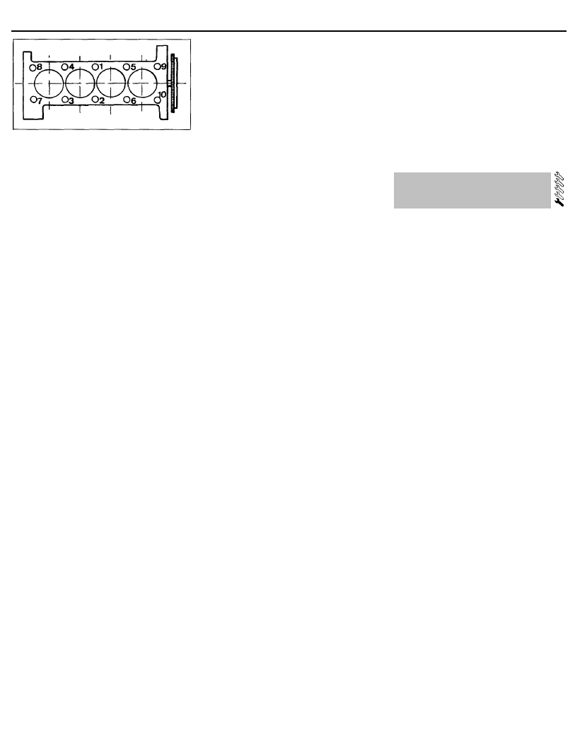
2B•18 XU series engine in-car engine repair procedures
12.61 Cylinder head bolt tightening
sequence
59 Apply a smear of grease to the threads,
and to the underside of the heads, of the
cylinder head bolts. Citroen recommend the
use of Molykote G10 grease (available from
your Citroen dealer); in the absence of the
specified grease, any good-quality high-
melting-point grease may be used.
60 Carefully enter each bolt and washer into
its relevant hole (do not drop it in) and screw it
in finger-tight, not forgetting to fit the spacer
to the front left-hand bolt.
61 Working progressively and in the
sequence shown, tighten the cylinder head
bolts to their stage 1 torque setting, using a
torque wrench and suitable socket (see
illustration).
62 Once all the bolts have been tightened to
their stage 1 torque setting, fully slacken all
the head bolts, working in the reverse of the
tightening sequence. Once the bolts are
loose, tighten all bolts to their stage 2
specified torque setting, again following the
specified sequence.
63 With all the bolts tightened to their stage 2
setting, working again in the specified
sequence, angle-tighten the bolts through the
specified stage 3 angle, using a socket and
extension bar. It is recommended that an
angle-measuring gauge is used during this
stage of tightening, to ensure accuracy. If a
gauge is not available, use white paint to
make alignment marks between the bolt head
and cylinder head prior to tightening; the
marks can then be used to check that the bolt
has rotated sufficiently.
64 Once the cylinder head bolts are correctly
tightened, reconnect the wiring connector to
the ignition HT coil. Otherwise, if the head was
stripped for overhaul, refit the HT coil or
distributor (as applicable), as described in
Chapter 5.
65 Fit the timing belt over the camshaft
sprocket. Refit the mounting bracket to the
end of the cylinder head, and securely tighten
its retaining bolts. Refit the engine right-hand
mounting bracket, and tighten its retaining
nuts to the specified torque. The jack can then
be removed from underneath the engine.
66 On early (pre-1992) models with a semi-
automatic timing belt tensioner, refit and
tension the timing belt as described in
paragraphs 40 to 44 of Section 8.
67 On later (1992-on) models with a
manually-adjusted belt tensioner pulley, refit
the belt to the camshaft sprocket as
described in paragraphs 40 and 41 of Section
8. Tension the belt as described in paragraphs
38 to 43 of Section 7.
68 The remainder of the refitting procedure is
a reversal of removal, noting the following
points:
(a) Ensure that all wiring is correctly routed,
and that all connectors are securely
reconnected to the correct components.
(b) Ensure that the coolant hoses are
correctly reconnected, and that their
retaining clips are securely tightened.
(c) Ensure that all vacuum/breather hoses are
correctly reconnected.
(d) Refit the cylinder head cover as described
in Section 4.
(e) Reconnect the exhaust system to the
manifold, refit the air cleaner housing and
ducts, and adjust the accelerator cable,
as described in Chapter 4. If the
manifolds were removed, refit these as
described in Chapter 4.
(f) On completion, refill the cooling system
as described in Chapter 1, and reconnect
the battery.
1761 cc models
69 Refit the cylinder head as described
above in paragraphs 58 to 65!
70 Refit the timing belt to the camshaft
sprocket as described in paragraphs 40 and
41 of Section 8, and tension the belt as
described in paragraphs 38 to 43 of Section 7.
71 The remainder of the refitting procedure is
a reversal of removal, noting the points made
in paragraph 68.
1998 cc 8-valve models
72 Refit the cylinder head as described
above in paragraphs 58 to 60, noting the
following points:
(a) Ensure that new head bolts and washers
are used.
(b) Ignore the remark about the spacer fitted
to the front left-hand bolt.
73 Working progressively and in the
sequence shown in illustration 12.61, tighten
the cylinder head bolts to their stage 1 torque
setting, using a torque wrench and suitable
socket.
74 Once all the bolts are tightened to their
stage 1 torque setting, tighten all bolts to their
stage 2 specified torque setting, again
following the specified sequence.
75 Working in the specified sequence, angle-
tighten the bolts through the specified stage 3
angle, using a socket and extension bar,
referring to the information given in para-
graph 63.
76 Once the cylinder head bolts are correctly
tightened, reconnect the wiring connector to
the ignition HTcoil. Otherwise, if the head was
stripped for overhaul, refit the HT coil or
distributor (as applicable), as described in
Chapter 5.
77 Refit the timing belt to the camshaft
sprocket as described in paragraphs 40 and
41 of Section 8, and tension the belt as
described in paragraphs 38 to 43 of Section 7.
78 The remainder of the refitting procedure is
a reversal of removal, noting the points made
in paragraph 68.
1998 cc 16-valve models
79 Refit the cylinder head using the
information given in paragraphs 72 to 75.
80 Refit the camshafts as described in
Section 10.
81 The remainder of the refitting procedure is
a direct reversal of removal, noting the
relevant points made in paragraph 68.
13 Sump - removal and refitting
Removal
1 Disconnect the battery negative lead.
2 Drain the engine oil, then clean and refit the
engine oil drain plug, tightening it securely. If
the engine is nearing its service interval when
the oil and filter are due for renewal, it is
recommended that the filter is also removed,
and a new one fitted. After reassembly, the
engine can then be refilled with fresh oil. Refer
to Chapter 1 for further information.
3 Apply the handbrake, jack up the front of
the vehicle and support it on axle stands.
4 On models with air conditioning, where the
compressor is mounted onto the side of the
sump, remove the drivebelt as described in
Chapter 1. Unbolt the compressor, and
position it clear of the sump. Support the
weight of the compressor by tying it to the
vehicle, to prevent any excess strain being
placed on the compressor lines. Do not
disconnect the refrigerant lines from the
compressor (refer to the warnings given in
Chapter 3).
5 Where necessary, disconnect the wiring
connector from the oil temperature sender
unit, which is screwed into the sump.
6 Progressively slacken and remove all the
sump retaining bolts. Since the sump bolts
vary in length, remove each bolt in turn, and
store it in its correct fitted order by pushing it
through a clearly-marked cardboard template.
This will avoid the possibility of installing the
bolts in the wrong locations on refitting.
7 Break the joint by striking the sump with the
palm of your hand. Lower the sump, and
withdraw it from underneath the vehicle.
Remove the gasket (where fitted), and discard
it; a new one must be used on refitting.
8 While the sump is removed, take the
opportunity to check the oil pump pick-
up/strainer for signs of clogging or splitting. If
necessary, remove the pump as described in
Section 14, and clean or renew the strainer.
9 On some models, a large spacer plate is
fitted between the sump and the base of the
cylinder block/crankcase. If this plate is fitted,
undo the two retaining screws from
diagonally-opposite corners of the plate.
Remove the plate from the base of the engine,
noting which way round it is fitted.
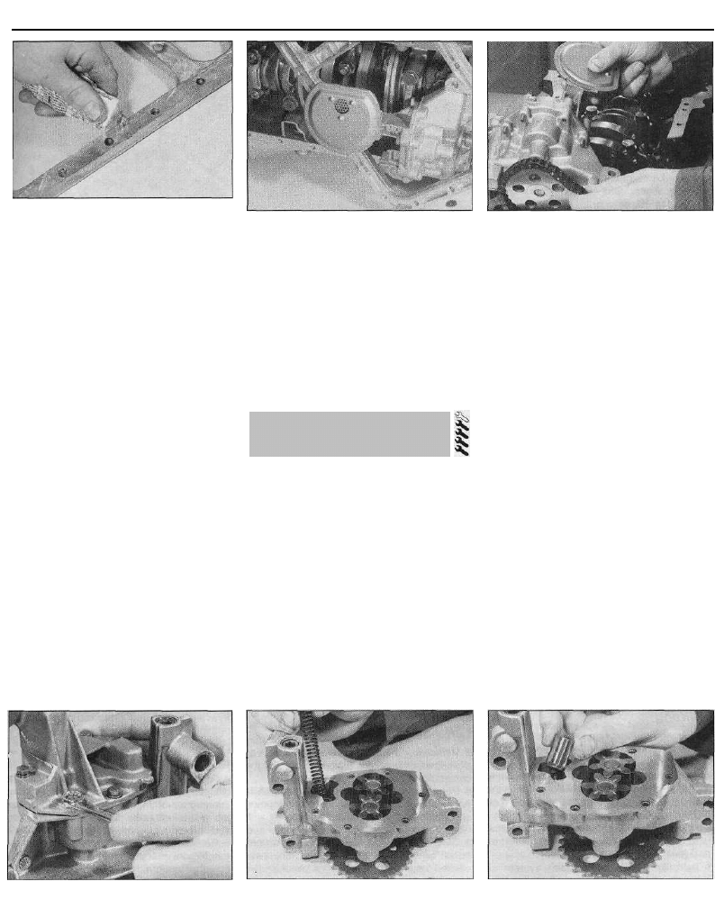
XU series engine in-car engine repair procedures 2B•19
13.10a Where a sump spacer plate is
fitted, apply a coat of suitable sealant to
the plate upper surface . . .
Refitting
9 Clean all traces of sealant/gasket from the
mating surfaces of the cylinder
block/crankcase and sump, then use a clean
rag to wipe out the sump and the engine's
interior.
10 Where a spacer plate is fitted, remove all
traces of sealant/gasket from the spacer
plate, then apply a thin coating of suitable
sealant (see paragraph 11) to the plate upper
mating surface (see illustration). Offer up the
plate to the base of the cylinder
block/crankcase, and securely tighten its
retaining screws.
11 On models where the sump was fitted
without a gasket (cast-aluminium sump),
ensure that the sump mating surfaces are
clean and dry, then apply a thin coating of
suitable sealant to the sump mating surface.
Citroen recommend the use of Auto-Joint E10
sealant (available from your Citroen dealer); in
the absence of the specified sealant, any
good-quality sealant may be used.
12 On models where the sump was fitted
with a gasket (pressed-steel sump), ensure
that all traces of the old gasket have been
removed, and that the sump mating surfaces
are clean and dry. Position the new gasket on
the top of the sump, using a dab of grease to
hold it in position.
13 Offer up the sump to the cylinder
block/crankcase. Refit its retaining bolts,
ensuring that each is screwed into its original
location. Tighten the bolts evenly and
13.10b . . . then refit the plate to the base
of the cylinder block/crankcase
progressively to the specified torque setting.
14 Where necessary, align the air
conditioning compressor with its mountings
on the sump, and insert the retaining bolts.
Securely tighten the compressor retaining
bolts, then refit the drivebelt as described in
Chapter 1.
15 Reconnect the wiring connector to the oil
temperature sensor (where fitted).
16 Lower the vehicle to the ground, then refill
the engine with oil as described in Chapter 1.
Removal
1 Remove the sump as described in Section
13.
2 Where necessary, undo the two retaining
screws, and slide the sprocket cover off the
front of the oil pump.
3 Slacken and remove the three bolts
securing the oil pump to the base of the
cylinder block/crankcase. Disengage the
pump sprocket from the chain, and remove
the oil pump (see illustration). Where
necessary, also remove the spacer plate
which is fitted behind the oil pump.
Inspection
4 Examine the oil pump sprocket for signs of
damage and wear, such as chipped or
14.3 Removing the oil pump
missing teeth. If the sprocket is worn, the
pump assembly must be renewed, since the
sprocket is not available separately. It is also
recommended that the chain and drive
sprocket, fitted to the crankshaft, be renewed
at the same time. To renew the chain and
drive sprocket, first remove the crankshaft
timing belt sprocket as described in Section 8.
Unbolt the oil seal carrier from the cylinder
block. The sprocket and chain can then be
slid off the end of the crankshaft. Refer to
Part C for further information.
5 Slacken and remove the bolts (along with
the baffle plate, where fitted) securing the
strainer cover to the pump body. Lift off the
strainer cover, and take off the relief valve
piston and spring, noting which way round
they are fitted (see illustrations).
6 Examine the pump rotors and body for
signs of wear ridges or scoring. If worn, the
complete pump assembly must be renewed.
7 Examine the relief valve piston for signs of
wear or damage, and renew if necessary. The
condition of the relief valve spring can only be
measured by comparing it with a new one; if
there is any doubt about its condition, it
should also be renewed. Both the piston and
spring are available individually.
8 Thoroughly clean the oil pump strainer with
a suitable solvent, and check it for signs of
clogging or splitting. If the strainer is
damaged, the strainer and cover assembly
must be renewed.
9 Locate the relief valve spring and piston in
14.5a Remove the oil pump cover
retaining bolts . . .
14.5b . . . then lift off the cover and
remove the spring . . .
14.5c . . . and relief valve piston, noting
which way round it is fitted
14 Oil pump - removal,
inspection and refitting
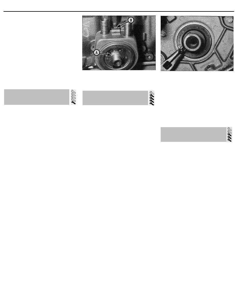
2B•20 XU series engine in-car engine repair procedures
the strainer cover. Refit the cover to the pump
body, aligning the relief valve piston with its
bore in the pump. Refit the baffle plate (where
fitted) and the cover retaining bolts, and
tighten them securely.
Refitting
10 Offer up the spacer plate (where fitted),
then locate the pump sprocket with its drive
chain. Seat the pump on the base of the
cylinder block/crankcase. Refit the pump
retaining bolts, and tighten them to the
specified torque setting.
11 Where necessary, slide the sprocket
cover into position on the pump. Refit its
retaining bolts, tightening them securely.
12 Refit the sump as described in Section 13.
Removal
1 Firmly apply the handbrake, then jack up
the front of the vehicle and support it on axle
stands.
2 Drain the cooling system as described in
Chapter 1. Alternatively, clamp the oil cooler
coolant hoses directly above the cooler, and
be prepared for some coolant loss as the
hoses are disconnected.
3 Position a suitable container beneath the oil
filter. Unscrew the filter using an oil filter
removal tool if necessary, and drain the oil
into the container. If the oil filter is damaged or
distorted during removal, it must be renewed.
Given the low cost of a new oil filter relative to
the cost of repairing the damage which could
result if a re-used filter springs a leak, it is
probably a good idea to renew the filter in any
case.
4 Release the hose clips, and disconnect the
coolant hoses from the oil cooler.
5 Unscrew the oil cooler/oil filter mounting
bolt from the cylinder block, and withdraw the
cooler. Note the locating notch in the cooler
flange, which fits over the lug on the cylinder
block (see illustration). Discard the oil cooler
sealing ring; a new one must be used on
refitting.
Refitting
6 Fit a new sealing ring to the recess in the
rear of the cooler, then offer the cooler to the
cylinder block.
7 Ensure that the locating notch in the cooler
flange is correctly engaged with the lug on the
cylinder block, then refit the mounting bolt
and tighten it securely.
8 Fit the oil filter, then lower the vehicle to the
ground. Top-up the engine oil level as
described in Chapter 1.
9 Refill or top-up the cooling system as
described in Chapter 1 (as applicable). Start
the engine, and check the oil cooler for signs
of leakage.
15.5 Oil cooler/oil filter mounting bolt (A)
and locating notch (B) - 1998 cc 16-valve
models
16 Crankshaft oii seals - renewal
Right-hand oil seal
1 Remove the crankshaft sprocket and
flanged spacer as described in Section 8.
Secure the timing belt clear of the working
area, so that it cannot be contaminated with
oil. Make a note of the correct fitted depth of
the seal in its housing.
2 Punch or drill two small holes opposite
each other in the seal. Screw a self-tapping
screw into each, and pull on the screws with
pliers to extract the seal (see illustration).
Alternatively, the seal can be levered out of
position. Use a flat-bladed screwdriver, and
take great care not to damage the crankshaft
shoulder or seal housing.
3 Clean the seal housing, and polish off any
burrs or raised edges, which may have
caused the seal to fail in the first place.
4 Lubricate the lips of the new seal with clean
engine oil, and carefully locate the seal on the
end of crankshaft. Note that its sealing lip
must be facing inwards. Take care not to
damage the seal lips during fitting.
5 Fit the new seal using a suitable tubular
drift, such as a socket, which bears only on
the hard outer edge of the seal. Tap the seal
into position, to the same depth in the housing
as the original was prior to removal.
6 Wash off any traces of oil, then refit the
crankshaft sprocket as described in Section 8.
Left-hand oil seal
7 Remove the flywheel/driveplate as
described in Section 17. Make a note of the
correct fitted depth of the seal in its housing.
8 Punch or drill two small holes opposite
each other in the seal. Screw a self-tapping
screw into each, and pull on the screws with
pliers to extract the seal.
9 Clean the seal housing, and polish off any
burrs or raised edges, which may have
caused the seal to fail in the first place.
10 Lubricate the lips of the new seal with
clean engine oil, and carefully locate the seal
on the end of the crankshaft.
16.2 Using a self-tapping screw and pliers
to remove the crankshaft oil seal
11 Fit the new seal using a suitable tubular
drift, which bears only on the hard outer edge
of the seal. Drive the seal into position, to the
same depth in the housing as the original was
prior to removal.
12 Wash off any traces of oil, then refit the
flywheel/driveplate as described in Sec-
tion 17.
Removal
Flywheel (models with manual
transmission)
1 Remove the transmission as described in
Chapter 7A, then remove the clutch assembly
as described in Chapter 6.
2 Prevent the flywheel from turning by locking
the ring gear teeth with a similar arrangement
to that shown in illustration 5.3 (Section 5).
Alternatively, bolt a strap between the
flywheel and the cylinder block/crankcase. Do
not attempt to lock the flywheel in position
using the crankshaft pulley locking pin
described in Section 3.
3 Slacken and remove the flywheei retaining
bolts, and remove the flywheel from the end
of the crankshaft. Be careful not to drop it; it is
heavy. If the flywheel locating dowel is a loose
fit in the crankshaft end, remove it and store it
with the flywheel for safe-keeping. Discard the
flywheel bolts; new ones must be used on
refitting.
Driveplate (models with automatic
transmission)
4 Remove the transmission as described in
Chapter 7B. Lock the driveplate as described
in paragraph 2. Mark the relationship between
the torque converter plate and the driveplate,
and slacken all the driveplate retaining bolts.
5 Remove the retaining bolts, along with the
torque converter plate and the two shims (one
fitted on each side of the torque converter
plate). Note that the shims are of different
thickness, the thicker one being on the
outside of the torque converter plate. Discard
15 Oil cooler (1998 cc 16-valve
models) - removal and refitting
17 Flywheel/driveplate - removal,
inspection and refitting
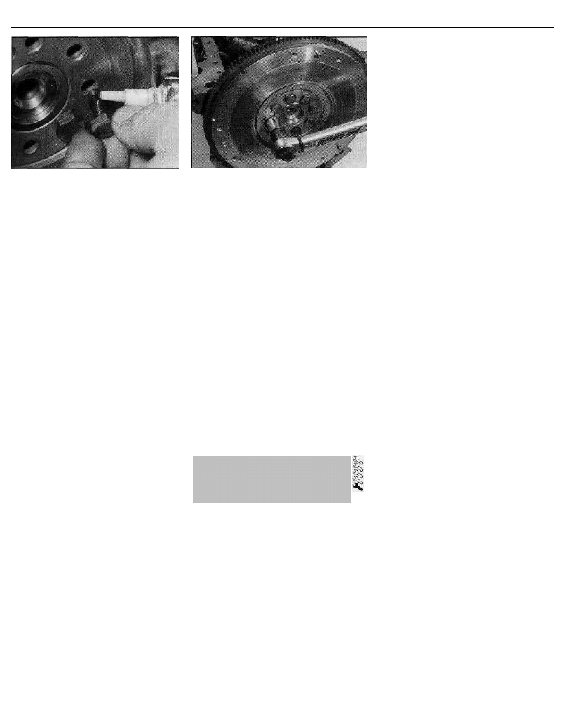
XU series engine in-car engine repair procedures 2B•21
17.10 If the new flywheel bolt threads are
not supplied with their threads pre-coated,
apply a suitable locking compound
to them . . .
the driveplate retaining bolts; new ones must
be used on refitting.
6 Remove the driveplate from the end of the
crankshaft. If the locating dowel is a loose fit
in the crankshaft end, remove it and store it
with the driveplate for safe-keeping.
Inspection
7 On models with manual transmission,
examine the flywheel for scoring of the clutch
face, and for wear or chipping of the ring gear
teeth. If the clutch face is scored, the flywheel
may be surface-ground, but renewal is
preferable. Seek the advice of a Citroen dealer
or engine reconditioning specialist to see if
machining is possible. If the ring gear is worn
or damaged, the flywheel must be renewed,
as it is not possible to renew the ring gear
separately.
8 On models with automatic transmission,
check the torque converter driveplate
carefully for signs of distortion. Look for any
hairline cracks around the bolt holes or
radiating outwards from the centre, and
inspect the ring gear teeth for signs of wear or
chipping. If any sign of wear or damage is
found, the driveplate must be renewed.
Refitting
Flywheel - models with manual
transmission
9 Clean the mating surfaces of the flywheel
and crankshaft. Remove any remaining
locking compound from the threads of the
crankshaft holes, using the correct-size tap, if
available.
10 If the new flywheel retaining bolts are not
supplied with their threads already pre-
coated, apply a suitable thread-locking
compound to the threads of each bolt. Citroen
recommend the use of Frenetanch E3
(available from your Citroen dealer); in the
absence of this, any good-quality locking
compound may be used (see illustration).
11 Ensure the locating dowel is in position.
Offer up the flywheel, locating it on the dowel,
and fit the new retaining bolts.
12 Lock the flywheel using the method
employed on dismantling, and tighten the
17.12 . . . then refit the flywheel, and
tighten the bolts to the specified torque
retaining bolts to the specified torque (see
illustration).
13 Refit the clutch as described in Chapter 6.
Remove the flywheel locking tool, and refit the
transmission as described in Chapter 7A.
Driveplate - models with automatic
transmission
14 Carry out the operations described above
in paragraphs 9 and 10, substituting
"driveplate" for all references to the flywheel.
15 Locate the driveplate on its locating
dowel.
16 Offer up the torque converter plate, with
the thinner shim positioned behind the plate
and the thicker shim on the outside, and align
the marks made prior to removal.
17 Fit the new retaining bolts, then lock the
driveplate using the method employed on
dismantling. Tighten the retaining bolts to the
specified torque wrench setting.
18 Remove the driveplate locking tool, and
refit the transmission as described in Chap-
ter 7B.
Inspection
1 If improved access is required, raise the
front of the car and support it securely on axle
stands.
2 Check the mounting rubber to see if it is
cracked, hardened or separated from the
metal at any point; renew the mounting if any
such damage or deterioration is evident.
3 Check that all the mounting's fasteners are
securely tightened; use a torque wrench to
check if possible.
4 Using a large screwdriver or a crowbar,
check for wear in the mounting by carefully
levering against it to check for free play.
Where this is not possible, enlist the aid of an
assistant to move the engine/transmission
unit back and forth, or from side to side, while
you watch the mounting. While some free play
is to be expected even from new
components, excessive wear should be
obvious. If excessive free play is found, check
first that the fasteners are correctly secured,
then renew any worn components as
described below.
Renewal
Right-hand mounting -1580 cc,
1761 cc and 1905 cc models
5 Disconnect the battery negative lead.
Release all the relevant hoses and wiring from
their retaining clips, and position clear of the
mounting so that they do not hinder the
removal procedure.
6 Place a jack beneath the engine, with a
block of wood on the jack head. Raise the
jack until it is supporting the weight of the
engine.
7 Slacken and remove the three nuts
securing the right-hand mounting bracket to
the engine unit. Remove the single nut
securing the bracket to the mounting rubber,
and lift off the bracket.
8 Lift the rubber buffer plate off the mounting
rubber stud, then unscrew the mounting
rubber from the body and remove it from the
vehicle. If necessary, the mounting bracket
can be unbolted and removed from the side of
the cylinder head.
9 Check all components carefully for signs of
wear or damage, and renew them where
necessary.
10 On reassembly, screw the mounting
rubber into the vehicle body, and tighten it
securely. Where removed, refit the mounting
bracket to the side of the cylinder head, and
securely tighten its retaining bolts.
11 Refit the rubber buffer plate to the
mounting rubber stud, and install the
mounting bracket.
12 Tighten the mounting bracket retaining
nuts to the specified torque setting.
13 Remove the jack from underneath the
engine, and reconnect the battery negative
terminal.
Right-hand mounting -1998 cc
8-valve and 16-valve models
14 Disconnect the battery negative lead.
Release all the relevant hoses and wiring from
their retaining clips. Place the hoses/wiring
clear of the mounting so that the removal
procedure is not hindered.
15 Place a jack beneath the engine, with a
block of wood on the jack head. Raise the
jack until it is supporting the weight of the
engine.
16 Undo the two bolts securing the curved
mounting retaining plate to the body. Lift off
the plate, and withdraw the rubber damper
from the top of the mounting bracket.
17 Slacken and remove the two nuts and two
bolts securing the right-hand engine/
transmission mounting bracket to the engine.
Remove the single nut securing the bracket to
the mounting rubber, and lift off the bracket.
18 Lift the rubber buffer plate off the
mounting rubber stud, then unscrew the
mounting rubber from the body and remove it
18 Engine/transmission
mountings -
inspection and renewal

2B•22 XU series engine in-car engine repair procedures
from the vehicle. If necessary, the mounting
bracket can be unbolted and removed from
the front of the cylinder block.
19 Check all components carefully for signs
of wear or damage, and renew as necessary.
20 On reassembly, screw the mounting
rubber into the vehicle body, and tighten it
securely. Where removed, refit the mounting
bracket to the front of the cylinder block, and
securely tighten its retaining bolts.
21 Refit the rubber buffer plate to the
mounting rubber stud, and install the
mounting bracket.
22 Tighten the mounting bracket retaining
nuts to the specified torque setting, and
remove the jack from underneath the engine.
23 Refit the rubber damper to the top of the
mounting bracket, and refit the curved
retaining plate. Tighten the retaining plate
bolts to the specified torque, and reconnect
the battery.
Left-hand mounting
24 Remove the battery and battery tray, as
described in Chapter 5. Slacken and remove
the battery support plate mounting bolts.
Release the wiring from its retaining clip on
the plate, and remove the plate from the
engine compartment.
25 Place a jack beneath the transmission,
with a block of wood on the jack head. Raise
the jack until it is supporting the weight of the
transmission.
26 Slacken and remove the centre nut and
washer from the left-hand mounting. Undo the
two bolts securing the mounting bracket
assembly to the vehicle body, and remove the
assembly from the mounting stud.
27 Slide the spacer off the mounting stud,
then unscrew the stud from the top of the
transmission housing, and remove it along
with its washer. If the mounting stud is tight, a
universal stud extractor can be used to
unscrew it.
28 Check all components carefully for signs
of wear or damage, and renew as necessary.
29 Clean the threads of the mounting stud,
and apply a coat of thread-locking compound
to its threads. Refit the stud and washer to the
top of the transmission, and tighten it to the
specified torque setting.
30 Slide the spacer onto the mounting stud,
then refit the mounting bracket assembly.
Tighten both the mounting bracket-to-body
bolts and the mounting centre nut to their
specified torque settings, and remove the jack
from underneath the transmission.
31 Refit the battery support plate, tightening
its retaining bolts securely, then refit the
battery as described in Chapter 5.
Rear mounting
32 Refer to Part A of this Chapter, Sec-
tion 15.
Wyszukiwarka
Podobne podstrony:
02b Rozkład normalnyid 4039 ppt
zx 01
zx 00
zx 04d
zx 08
Cw 01B M 02B Wahadło fizyczne
sta zag zycia 11 03 02b
0656PWsrTz1 Rysunek 02b
zx 10
zx 04c
02B
MetStatChem 02b notatki
zx 07a
zx 02a
PREZENTACJA FIRMY „X
Fig-02b
02B Z dziećmi o śmierci 19 04-2008, KSW Kędzierzyn spotkania, Spotkania i sprawozadnia K-K KSW
02b Kapcie na drutach opis
więcej podobnych podstron