
S E R V I C E
Whirlpool Europe
Customer Services
Model
MT 243
Version
8538 243 01291
Page
Introduction safety
2
Technical data
3
Text/Legend
4 - 10
Spare part list
11
Exploded view
12
Wiring diagram
13
Program diagram
14 - 15
Service Manual
Microwave oven
MT 243
MT 243
This documentation is only intended for qualified technicians who are aware of the respec-
tive safety regulations.
Date: 21.09.1998
Subject to modification
Document-No.: 4812 714 12449

S E R V I C E
21.09.1998 / Page 2
MT 243
Whirlpool Europe
Doc. No: 4812 714 12449
8538 243 01291
Customer Service
Introduction safety
INTRODUCTION
Before leaving the factory each oven is carefully checked.
It must, however, be installed and used correctly.
Despite all the steps taken to make the oven safe, the safety is dependent on the correct installation and the fact
the user understands how to use and maintain the oven.
The information in this section should be used as a reminder that the oven is safe and that anyone who uses it must
first read the instructions for use in order to be able to use the oven correctly and obtain best results.
SAFETY
To avoid injury to yourself and damage to the appliance always work to the following rules when servicing an oven.
Always disconnect the plug from the mains before starting work.
If there is no plug switch off the electric supply at the control box.
When you have finished servicing an oven before you reconnect it to the mains, make sure that:
- all the internal connections are correct
- the wires are insulated and not touching the door or the cabinet or anything sharp
- all the earth connections are electrically and mechanically sound
- do not modify or anyway interfere with the safety devices built-in to the oven
- make sure that each replacement part you use conforms to the manufacturer´s specifications
Do not start a repair if you have any doubt as to your ability to complete it.
CAUTION - MICROWAVE RADIATION
PERSONNEL SHOULD NOT BE EXPOSED TO THE MICROWAVE ENERGY WHICH MAY RADIATE FROM THE MAGNETRON,
WAVEGUIDE OR ANTENNA IF THEY ARE IMPROPERLY USED OR CONNECTED. ALL INPUT
AND OUTPUT MICROWAVE CONNECTIONS, WAVEGUIDES, FLANGES AND GASKETS MUST BE SECURE.
NEVER OPERATE THE DEVICE WITHOUT A MICROWAVE ENERGY ABSORBING LOAD ATTACHED.
NEVER LOOK INTO AN OPEN WAVEGUIDE OR ANTENNA WHILE THE DEVICE IS ENERGIZED.
NEVER OPERATE AN OVEN WITH CABINET OFF WITHOUT MEASURING THE MICROWAVE LEAKAGE
AROUND MAGNETRON AND VISIBLE MICROWAVE CONNECTIONS (WELDING JOINTS).
Do not operate the oven if the following conditions exist:
- the door does not close firmly against the door support because of the door being warped or the hinges damaged.
- The door trims or seals are damaged.
- If there is any visible damage to the oven.
- if the door does not close properly.
Avoid operating the oven if known components in the interlock system, oven door or microwave
generating assembly are known defective. They must be replaced.
WARNING - HIGH VOLTAGE
IT IS POSSIBLE TO COME IN CONTACT WITH LETHAL HIGH VOLTAGE WHEN WORKING WITH
HV TRANSFORMER, HV CAPACITOR AND MAGNETRON. THEREFORE NEVER TRY TO MEASURE
THE HIGH VOLTAGE. ALWAYS TAKE UTMOST CARE WHEN PERFORMING ELECTRIC
MEASUREMENTS INSIDE THE OVEN.
S E R V I C E
Whirlpool Europe
MT 243
21.09.1998 / Page 3
Customer Service
8538 243 01291
Doc. No: 4812 714 12449
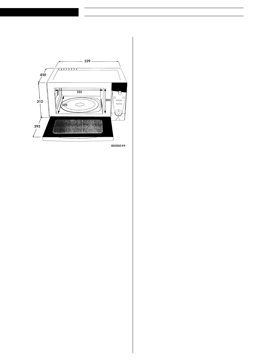
Technical data
Dimensions
Turntable
280
mm
Volume
26
l
Built in kit: AVM 124 (optional)
Electrical
Voltage
230/240V
Frequency
50 Hz
Total consumption 2500
W
Microwave
1650
W
Grill
950
W
Output power
Microwave
1000
W
Quartz grill
900
W
Weight
Gross
24
kg
Net
21
kg
Accessories
Instruction booklet, cookbook,
warranty booklet, crisp plate, handle
Features
- Electronic controls
- Quartz grill
- Crisp function
- Jet start
- Auto weight defrost
- Auto weight crisp
- Timed defrost 160 W
- Child lock
- 8 power levels
- 24 hour clock
- 90 minute timer

S E R V I C E
21.09.1998 / Page 4
MT 243
Whirlpool Europe
Doc. No: 4812 714 12449
8538 243 01291
Customer Service
Text/Legend
Short Form Functional Description MT 243 (El. Crisp VIP 2000)
Panel Design
turntable stop
a) Food Class Bar
b,d,e,f,g)
h) Grill symbols
i) MW symbols
c) 5 Digits
j) Fan symbols
k) Crisp Pan symbol
l) Turntable symbol
m) Power-/Temp-/Process-Bar

S E R V I C E
Whirlpool Europe
MT 243
21.09.1998 / Page 5
Customer Service
8538 243 01291
Doc. No: 4812 714 12449
Description of the Display Symbols
a) The Food Class Bar indicates the food class and is lit when auto defrost, auto crisp, auto crisp reheat or auto
crisp cook is selected.
b) "AUTO" is lit when auto defrost, auto reheat, beverage or auto crisp is selected.
c) "SENSE" or ”boil” is displayed when an auto function is started.
”HEAT” or ”COOK” is displayed when Auto Crisp Reheat or Auto Crisp Cook.
”JET” is displayed when using maximum MW power.
d) Personal preference for the auto functions is indicated by "-2", "-1","+1", "+2". When no personal preference is chosen,
all are turned off.
e) The defrost symbol is lit during manual or auto defrost.
f) The beverage symbol is lit when Beverage is selected.
g) The reheat symbol is lit when Auto Reheat, Auto Crisp Reheat, Auto Crisp Cook or Auto Boil is selected.
h) The grill symbol is lit when a function using the grill element is selected. The lower part of the symbol blinks
during cooking.
i) The MW symbols are lit when a function using microwaves is selected.
j) The fan symbol indicates that the convection function is in operation.
k) The pan symbol is lit when a crisp function is selected, indicating that the crisp pan must be used.
l) The plate symbol is lit when a cooking function is selected, indicating whether the turn table is rotating or not.
It flashes rapidly if the turntable is switched off when it must be rotating.
m) The Power-/Temp-/Process bar indicates:MW power. Jet is indicated by a rolling bar.
the temperature in convection heating.
how far the process has advanced when using the auto functions.
Real time clock
Time is set by pressing the CLOCK button. Set the hours with the timer knob. Press the CLOCK button again
and set the minutes with the timer knob. Finally, press the CLOCK button again to clear the seconds and start
the clock.
Cooking time
The cooking time is set with the timer knob. The maximum cooking time that can be set is 90 minutes.
Microwave power
To adjust the microwave power, press the POWER buttons. The current power level is displayed in Watts for 2
seconds. The power level is stepped with the POWER buttons, while the power level is displayed. If POWER is
pressed when the oven is in stand by, the power level is set to 750 W. The oven is started with the START
button.
JET
If the oven is in stand by and the START button is pressed, cooking is started immediately at full power. If the
oven is already cooking, the timer is incremented 30 seconds each time the button is pressed, but the power
setting is not affected.
Auto Defrost (El Crisp and Crisp Convection only)
Press the AUTO DEFROST button until the wanted Food Class is selected. See . Turn the rotacoder until the
shown weight corresponds as close as possible to the weight of the food. Press the START button. The time
needed will be calculated and the oven starts.
Note: The turntable must be rotating when using this function.

S E R V I C E
21.09.1998 / Page 6
MT 243
Whirlpool Europe
Doc. No: 4812 714 12449
8538 243 01291
Customer Service
Table 1 Food Classes for Auto Defrost
1
Auto Defrost Meat
50 g - 2.0 kg
2
Auto Defrost Fish
50 g - 2.0 kg
3
Auto Defrost Bread
50 g - 2.0 kg
4
Auto Defrost Vegetables
50 g - 2.0 kg
5
Auto Defrost Chicken / Chicken parts
50 g - 3.0 kg
Auto Crisp (El Crisp and Crisp Convection only)
Press the AUTO CRISP button until the wanted Food Class is selected. See . Turn the rotacoder until the
shown weight corresponds as close as possible to the weight of the food. Press the START button. The time
needed will be calculated and the oven starts.
Note: The turntable must be rotating when using this function.
Table 2 Food Classes for Auto Crisp
1 Auto Crisp Pizza
200 g - 600 g
2 Auto Crisp Pie/Quiche
200 g - 600 g
3 Auto Crisp Chicken Parts
200 g - 600 g
4 Auto Crisp Potato Products
200 g - 600 g
Crisp
Select crisp by pressing the CRISP button. Set the cooking time with timer knob and start with the START
button.
NOTE:The turntable must be rotating when using this function.
Grill
Use the GRILL button to select grill operation. Set the cooking time with timer knob and start with the START
button. The grill can be toggled on/off with the Grill button.
NOTE:- When the Crisp or Grill function is selected, grill indicator 1 is lit. When cooking is started, grill indicator
2 blinks.
NOTE2:- The turntable must be rotating when using GRILL only. Grill/MW-combination is allowed with
nonrotating turntable however.
Turn Table Stop
The Turn Table Stop switch is used to select between rotating and non rotating turntable. Some functions
require that the turntable is rotating however.
Stop
The STOP button aborts any operation started, and returns the oven to standby.
Microwave Power Control
Power table and timings
The peak microwave power is specified in the technical specification of the oven. To obtain lower power levels,
the magnetron is switched on and off. The cycle time is 20 seconds. The magnetron is on during a portion of
the cycle time, then it is switched off until the beginning of the next cycle. The on-time varies depending on
which power level has been selected.

S E R V I C E
Whirlpool Europe
MT 243
21.09.1998 / Page 7
Customer Service
8538 243 01291
Doc. No: 4812 714 12449
Table 3
Circuit description MT 243 El. Crisp VIP 2000 family
Transformer and Rectifier
El Crisp:
The voltages necessary to the control system are taken from transformer 5101. It has two secondary windings,
one 2.4V (RMS.) with a centre-tap, to drive the filament of the display, and one 25V (RMS.) winding to supply
the rest of the circuits. There is a thermal overload protection included in the transformer, to avoid insulation
breakdown in the case of short circuits on the secondary side. The primary and secondary circuits are
completely isolated from each other. The rectifier consists of diodes 6110, 6111, 6112 and 6113. The rectified
voltage is smoothed by capacitor 2210.
Fuzzy Crisp, Conv, Fuzzy Crisp Conv:
The voltages necessary to the control system are taken from transformer 5101. It has two secondary windings,
one 2.5V winding to drive the filament of the display, and one 20V (RMS) winding to supply the rest of the
circuits. There is a thermal overload protection included in the transformer, to avoid insulation breakdown in the
case of short circuits on the secondary side. The primary and secondary circuits are completely isolated from
each other.
The voltage is doubled in the circuit consisting of the diodes 6110 and 6112 and the capacitors 2101 and 2110.
Microcomputer
The oven is controlled by a single chip microcomputer. It contains RAM and ROM, timer and a clock generator.
The input- and output ports are used to control the display and relays, to read the keys and the rotary encoder.
and to measure the signals from the weight, humidity and temperature sensors. The clock generator uses an
external ceramic resonator to keep an accurate frequency.
VDD and micro processor reset
The voltage between VDD and VSS is regulated by zener diode 6222 and the base-emitter voltage of the
transistor 7222. At start-up the transistor is not conducting, so the reset-pin of 7000 is held low by the resistor
3223. When the voltage between VDD and VSS has increased to about 4.0 Volts, the base current of 7222 is
high enough to make the transistor conduct, and the reset-pin goes high.
When port P13 is set low the reset level is approximately 3 V. This function is used to avoid reset in some parts
of the program execution.
Current to the VDD is feed from either the F/L relay ( 4901) when this is activated or from transistor 7223 when
the relay is turned off.
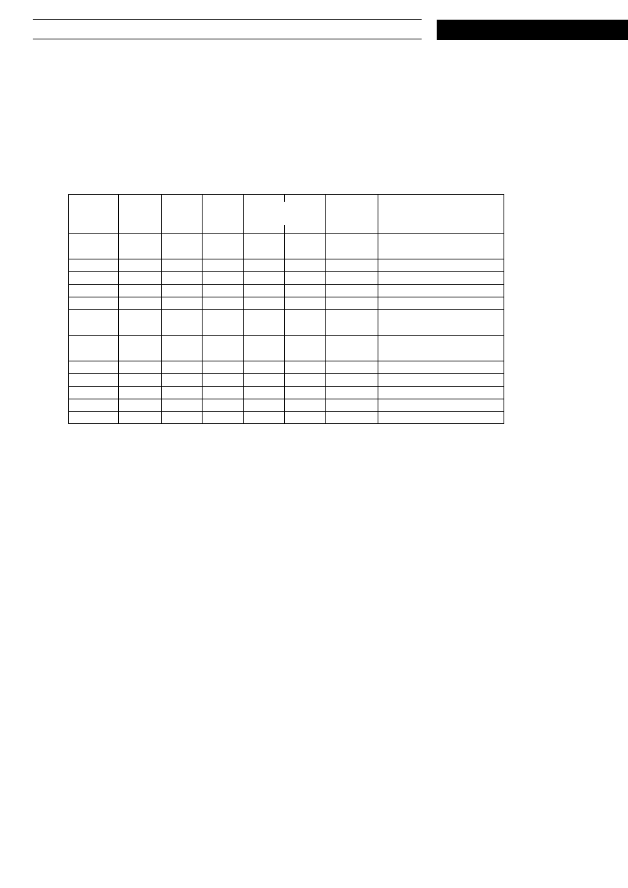
Tabelle 1:
Indicated
power W
Cycle
time s
On time from
contr. system
s
Start
delay
time s
Effective
on time s
90
20.5
3.5
1.5
2.0
160
20.5
5.0
1.5
3.5
350
20.5
9.0
1.4
7.6
500
20.5
12.1
1.3
10.8
650
20.5
15.3
1.2
14.1
750
20.5
17.2
1.0
16.2
850
20.5
18.9
0.5
18.4

S E R V I C E
21.09.1998 / Page 8
MT 243
Whirlpool Europe
Doc. No: 4812 714 12449
8538 243 01291
Customer Service
VKK, Diplay and Buzzer.
El Crisp:
Zener diode 6126 and transistor 7125 generates a stabilised voltage of approximately -22V DC.
This voltage supplies the midpoint of the transformer filament winding and the buzzer.
VKK voltages is supplied by a voltage divider (3127 and 3128) and emitter follower 7128.
Relay Driver Circuits
To prevent the relays from being activated if the processor is hung up, the relay driver is ac coupled. This
means that a pulse train on output P20 is necessary to activate the relays.
When any relay shall be activated the output of P20 will deliver pulses t
low
= 229 us and
t
high
= 15 us.
Transistor 7232 and 7134 is switched on when P20 goes low and they are switched of when P20 goes high.
Capacitor 2232 and resistor 3232 forms an integrator. The voltage over capacitor 2240 is equal to the average
voltage over the relay coils. When transistor 7134 is switched of the current in the relay coils continue to flow
through the diodes 6133.. The negative pole of 2232 goes to plus 0,6 V. If the voltage over 2232 exceeds the
zenervoltage of 6236 the zener diode will conduct and when P20 goes low and the transistors 7232 and 7134
can not switch on.
Transistors 7131, 7130, 7161, 7163 is used to switch on MW, Grill, FC heat and the FC fan
relays. The El Crisp does not contain the FC relays.
The F/L relay has to be on to enable any other relay to be activated.
When the door is open and the fan supply is interrupted by the secondary door switch, the frequency of the
pulse train on P20 is 340 Hz when the F/L relay shall be turned on. the dutycycle is 75 % (low) on the El Crisp
control and 58 % (low) on Fuzzy Crisp, Convection and Fuzzy Crisp Convection.
50 Hz Sensing Circuit
The 50Hz-signal is taken from the secondary winding of the mains transformer, before the rectifier. The
voltage is divided by 3210 and 3211 before it is fed to transistor 7211. Port G13/R32 of the micro processor is
normally high (Vss), except for a short moment when the voltage on the collector of 7211 is sensed once every
ms.
Feedback Circuit
The feed back circuit consists of 3101- 3106, 6105 and 7101. When a current flows through the LED of 7101 and
the output pin 4 is high and turns off transistor 7102. Port R61 of the micro processor is normally kept low
(Vss), except for a short moment when the voltage on 2201 is sensed. If 7102 is off the micro processor will
read a ”zero” and when 7202 is on the micro processor will read a ”one”. The RC time constant 2201 * 3201 is
only 5,6 us and will not influence the timing of the feedback signal.
Keyboard
All keyboard switches are connected in a matrix with four rows and four columns. The columns are pulled high,
one at a time, during scanning. The key scanning is combined with the display drive circuitry.
If any key is pressed, one of the processor inputs will be high when the corresponding output is high. The
inputs K00-K03 have internal pull down resistors.
When OTP is used external pull down resistors must be used ( 3285, 3286, 3287 and 3288).
Display
The display is of the vacuum fluorescent type. It is driven directly from the microprocessor high voltage
outputs. These are provided with internal pull down resistors. The display has a matrix of segments and grids.
The grids are continuously scanned by the processor, except for a pause during key scanning. Each grid is held
high for a moment, then there is a short blanking period before the next grid is activated. The segments are
pulled high when they should be lit during scanning.

S E R V I C E
Whirlpool Europe
MT 243
21.09.1998 / Page 9
Customer Service
8538 243 01291
Doc. No: 4812 714 12449
Buzzer with ping
By controlling the supply voltage to the Buzzer the volume can be controlled. This is used to form the clock-like
PING function. Transistor 7152 feeds the buzzer with the voltage over the capacitor 2152. The resistor 3152
discharges the capacitor logarithmically. This gives the clock like decay effect. The transistor 7153 loads the
capacitor again at request from the micro processor.
The buzzer (4625) voltage is switched by transistor 7251. The base of 7251 is fed with a 2048 Hz square wave
from the micro processor.
Error Codes
Certain fault conditions are indicated by an error code. The table covers all variants of the VIP 2000 range. The
following codes are implemented:
ERR 0 Convection temperature sensor fault
ERR 1 Short circuit in the MW relay
ERR 6 Weight sensor calibration has not been performed
ERR 7 Humidity sensor is defect or has not been connected
ERR 8 Impossible to write to E2PROM
ERR 9 Options have not been set
ERR A No wheel detected on weight sensor
ERR B No pulses from the weight sensor
Test Mode
The microprocessor program contains a test mode, in order to simplify checking and trouble shooting of the
control system. To enter test mode: Keep the STOP button pressed, open the door of the oven and force a
reset of the microprocessor. This can be done by short circuiting the base and emitter of 7202, or by
disconnecting the power at least two seconds. To exit test mode press the STOP button. The tables below
cover all variants of the VIP-2000 range.
Test Mode Entry
When test mode is entered, all segments in the display will be lit. Close the door. The Running mask number
is output to the display pins for 500 milliseconds. Then the mask number and the option setting will be
indicated in the following format:
MMMO2O1
Where MMM is the mask number and O1 and O2 are option 1 and option 2.
When the keys are affected, display segments and relays etc. are switched on and off according to table 2.
If no key has been touched for 30 seconds the oven leaves test mode.
When test mode is entered the following tests are initiated:
(Crisp Convection and Fuzzy Convection only)
Convection temperature reading. This takes approximately 5 seconds, then the temperature value is available
when any of FC or QH keys is pressed.
(Fuzzy Crisp and Fuzzy Crisp Convection only)
Start a fuzzy temperature reading. This takes approximately 5 seconds, then the temperature value is available
when M1 (Mem) is pressed.
Start a humidity sensor connection test. 8 seconds after test mode is entered, the PWM output is set low.
After 25 - 40 ms the R63 input is checked, and should be high. Then the PWM output is set high. After another
Tabelle 2:
Action
Reaction
Open the door
Press STOP and, at the same time,
connect power
All segments on the display are lit.
Close the door
The display will darken for half a second while
the Running mask number is output to the
display pins.
Mask number and Options will show on the
display in the format MMMOO (Ex: 1 02).
S E R V I C E
21.09.1998 / Page 10
MT 243
Whirlpool Europe
Doc. No: 4812 714 12449
8538 243 01291
Customer Service
25 - 40 ms the R63 input is checked, and should be low. If one of these checks fail, "ERR7" is displayed when
MICRO is pressed. After this connection test, the humidity sensor bridge is balanced.
Test Mode Functions
The following table is valid for processor 4619 678 4333x
Tabelle 3:
Key
Crisp
+ Conv.
Digit
F/L
relay
1901
Grill
relay
1904
FC
heat
1905
FC
fan
1907
Buzzer
Clock
5G
on
off
off
off
off
Toggles Buzzer com-
munication on/off
Aut Dfr
4G
on
off
off
off
off
Aut Cri
1G
on
off
off
off
off
Crisp
2G
on
on
off
off
off
Grill
3G
on
on
off
off
off
Forced
Conv.
Temp
on
off
on
on
off
Convection temp
measurement
Quich
Heat
Temp
on
on
on
on
off
Convection temp
measurement
Power -
2G
on
off
off
off
off
Power
3G
on
off
off
off
off
Power+
4G
on
off
off
off
off
Start
1G
off
off
off
off
off
Stop
off
off
off
off
off
off
Exit test mode

S E R V I C E
Whirlpool Europe
MT243
21.09.1998 / Page 11
Customer Service
8538 243 01291
Doc. No: 4812 714 12449
Spare part list
Model
MT 243
Service No.
853824301291
Version
853824301291
Pos. No. 12NC Code
Description
002 0
4819 442 38912
Cabinet
002 2
4819 442 38914
Cover Mica plate upper
013 0
4819 462 79423
Foot
041 0
4819 417 19547
Hinge left
041 1
4819 417 19548
Hinge right
041 2
4819 535 98354
Shaft
044 0
4819 492 48168
Spring
100 0
4819 442 38915
Door complete
120 0
4819 442 38917
Door,inner
121 0
4819 459 48832
Frame door inner
130 0
4819 404 79332
Unit,pushbutton for doorswitch
131 0
4819 535 38153
Lock door
131 1
4819 502 18402
Screw loock door,
141 0
4819 450 58203
Oven glass
143 0
4819 459 48831
Frame
234 0
4819 325 18122
Plate / Holder
234 1
4819 462 38878
Casing
246 0
4819 310 18538
Crisp plate VIP27
246 1
4819 498 78193
Handle crisp
255 0
4819 466 78405
Turntable
264 0
4819 535 79159
Rail
264 1
4819 462 38828
Guide for Crosspiece
301 0
4819 276 38351
Switch,pushbut.
305 0
4819 404 79333
Holder
320 0
4819 453 58732
Control panel
332 2
4819 410 28924
Button clockset
333 0
4819 410 28932
Button start
334 3
4819 410 28929
Button power
334 4
4819 412 58619
Knob timer
334 5
4819 410 28934
Button stop
334 6
4819 410 28936
Button tt-stop
334 7
4819 410 28927
Button plus
334 8
4819 410 28925
Button minus
352 0
4819 130 38083
Display
352 1
4819 450 58204
Glass for display
352 2
4819 462 38879
Display chart
355 0
4819 280 18029
Buzzer
404 0
4819 131 58019
Magnetron
404 1
4819 462 38875
Conveyor
404 2
4819 462 38874
Air guide
406 0
4819 361 18381
Motor TT
406 1
4819 502 18372
Screw for TT-Motor
406 2
4819 532 68686
Gasket ring
411 0
4819 148 68076
Transformer
412 0
4819 145 78207
Transformer,HT
420 0
4819 121 38012
Capacitor HT 240V
420 1
4819 404 78839
Bracket capacitor
421 0
4819 121 18162
Filter,mains
426 0
4819 121 18265
Diode HV
442 0
4819 361 18361
Motor Blower
442 1
4819 462 38876
Cap fan
442 2
4819 462 38877
Inlet fan
443 0
4819 515 28224
Fan wheel
452 0
4819 259 98557
Infraredelement
452 1
4819 325 18123
Reflector
Pos. No. 12NC Code
Description
485 0
4819 320 28025
Cable,HT
490 0
4819 321 18231
Cable,mains cpl. with clamp
502 0
4819 214 78594
Control unit
502 3
4819 101 48142
Potentiometer
505 0
4819 209 88058
Microprocessor
561 0
4819 282 48281
Thermostat for magnetron 125 C
564 0
4819 282 48275
Thermostat 165C
617 0
4819 280 68363
Relay
617 1
4819 280 68321
Relay
622 0
4819 276 18349
Switch VKS
622 1
4819 276 18273
Switch VKS
622 3
4819 271 38256
Switch
633 0
4819 276 18336
Switch, door
651 0
4819 134 28029
Lamp cavity 240V - 25W
911 0
4819 502 38274
Screw for trafo M4x16St
971 0
4819 252 28125
Fuse 10A
972 0
4819 252 28121
Fuse T100mA
S E R V I C E
21.09.1998 / Page 12
MT 243
Whirlpool Europe
Doc. No: 4812 714 12449
8538 243 01291
Customer Service
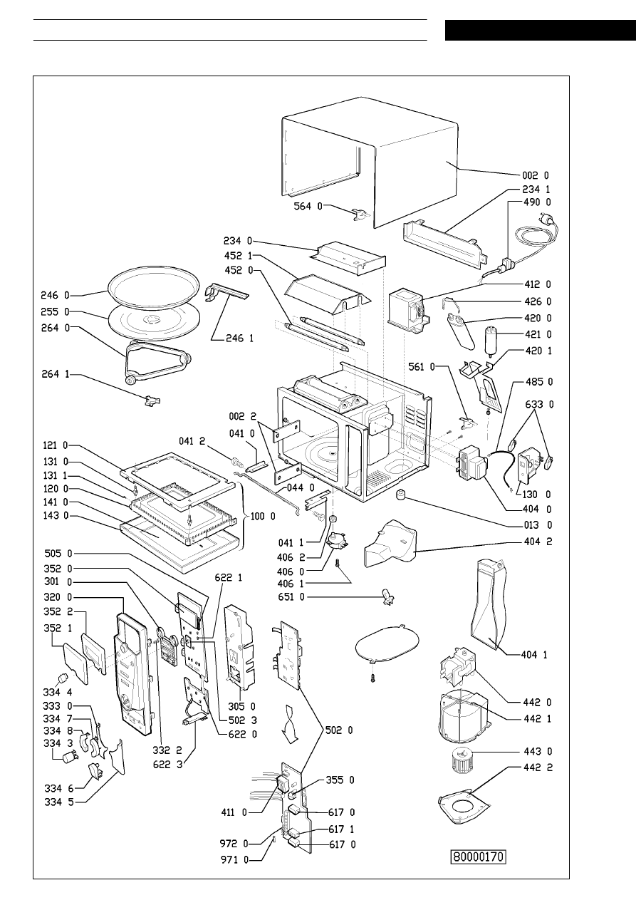
Exploded view
S E R V I C E
Whirlpool Europe
MT 243
21.09.1998 / Page 13
Customer Service
8538 243 01291
Doc. No: 4812 714 12449
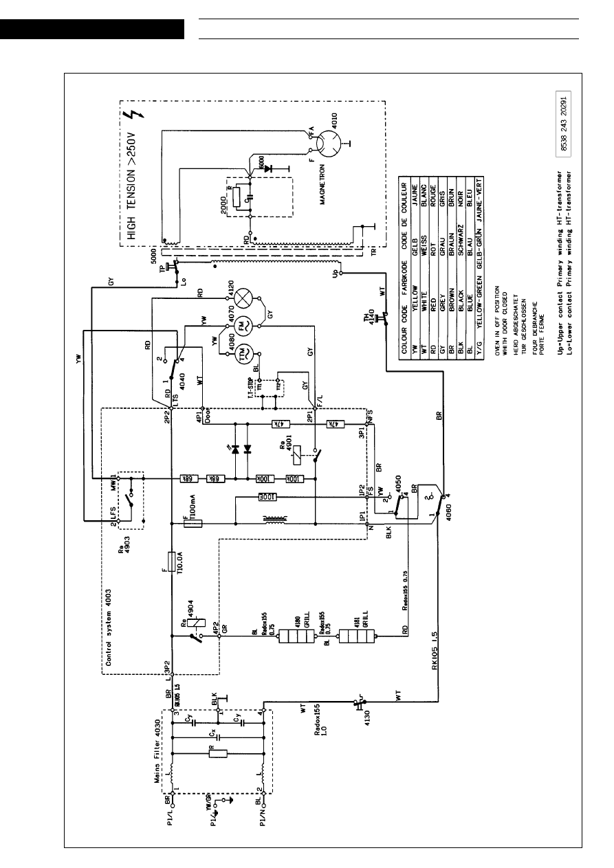
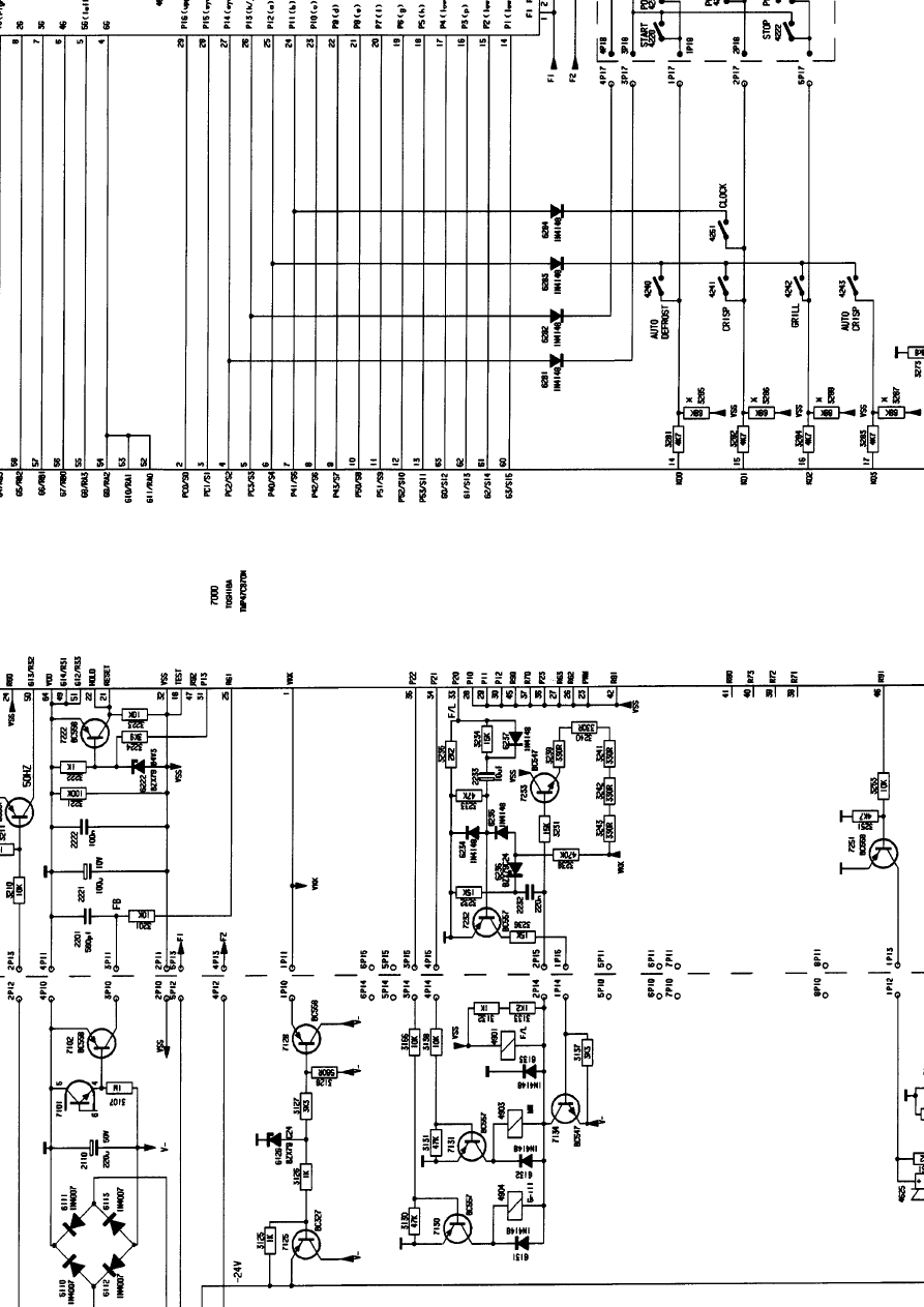
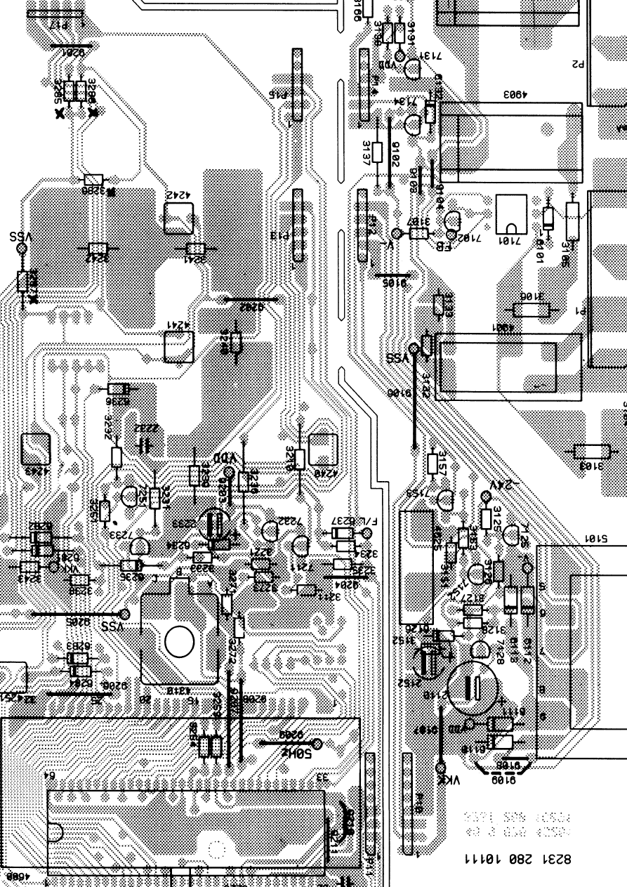
Wiring diagram
Wyszukiwarka
Podobne podstrony:
MIKROFLORA, ZATRUCIA POKARMOWE
A10 Diagnostyka zuzycia mikrofrezu
Mikroflora jelitowa, rola probiotyków w żywieniu
5-6, EIT, Mikrofale
Mikrofony z Tu 154 Nie wszystko co ważne stało się w kabinie
Podstawy biologii mikrofauny
Kuchnia MIKROFALOWKA PRZEPISY
e4b, mikrofale
Instrukcja BHP przy obsłudze kuchni mikrofalowej, szkoła, instrukcje
3-4, EIT, Mikrofale
27-28, EIT, Mikrofale
15-16, EIT, Mikrofale
Kuchenka mikrofalowa, Instrukcje-Bezpiecznej Pracy
Jak zrobić mikrofon z rolki po papierze toaletowym
sprawozdanie e4 polaryzacja mikrofal 1
e4 3 polaryzacja mikrofal
Mikroflora?rm sciaga
Mikrofalówka projekt PP
Rozchodzenie sie?l ultrakrótkich i mikrofal
więcej podobnych podstron