05256–15
–
DIAGNOSTICS
SUPPLEMENTAL RESTRAINT SYSTEM (April, 2003)
05–421
586
Author:
Date:
2004 COROLLA (RM1037U)
SUPPLEMENTAL RESTRAINT SYSTEM (Apr., 2003)
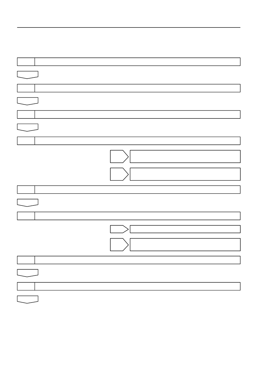
HOW TO PROCEED WITH TROUBLESHOOTING
The hand–held tester can be used at step 4, 6, 8 and 9.
1
VEHICLE BROUGHT TO WORKSHOP
2
CUSTOMER PROBLEM ANALYSIS (See page
05–423
)
3
WARNING LIGHT CHECK (See page
05–424
)
4
THE DTCs CHECK (Present and Past DTCs) (See page
05–424
)
DTCs IS OUTPUT (INCLUDING NORMAL SYS-
TEM CODE): Go to step 5
DTCs IS NOT OUTPUT: PROBLEM SYMPTOMS
TABLE (See page
05–436
)
5
THE DTCs CHART (See page
05–430
)
6
CIRCUIT INSPECTION (See page
05–437
to
05–579
)
TROUBLE CODE IS OUTPUT: Go to step 7
NORMAL SYSTEM CODE IS OUTPUT: Go to step
11
7
REPAIR
8
CLEAR THE DTCs (Present and Past DTCs) (See page
05–424
)
05–422
–
DIAGNOSTICS
SUPPLEMENTAL RESTRAINT SYSTEM (April, 2003)
587
Author:
Date:
2004 COROLLA (RM1037U)
9
THE DTCs CHECK (Present and Past DTCs) (See page
05–424
)
DTCs IS NOT OUTPUT: Go to step 10
DTCs IS OUTPUT: Go to step 5
10
SYMPTOM SIMULATION (See page
01–20
)
WARNING LIGHT REMAINS OFF: Go to step 11
WARNING LIGHT IS ON: Go to step 5
11
CONFIRMATION TEST
END
05257–12
[
]
[
]
[
]
H40122
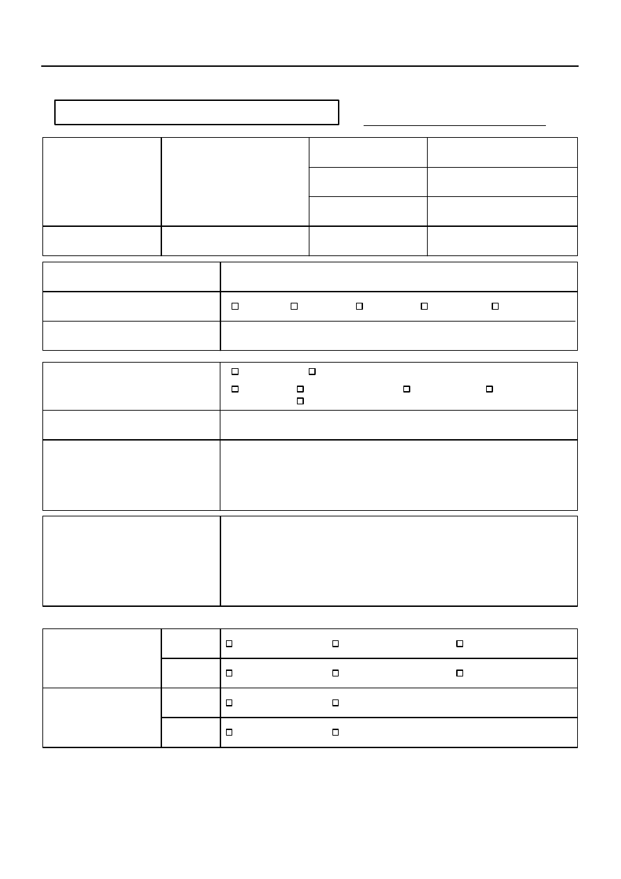
Supplemental Restraint System Check Sheet
Inspector’s
Name
Date Vehicle Brought In
Registration No.
Registration Year
Frame No.
Odometer Reading
km
Miles
Date Problem Occurred
Weather
Temperature
Fine
Cloudy
Rainy
Snowy
Other
Approx.
Starting
Idling
Driving
Constant speed
Acceleration
Deceleration
Other
Vehicle Operation
Road Condition
Details Of Problem
Vehicle Inspection, Repair Histo-
ry Prior to Occurrence of Mal-
function (Including Supplemen-
tal Restraint System)
Diagnosis System Inspection
SRS Warning Light
Inspection
DTC Inspection
1st Time
2nd Time
Remains ON
Does Not Light Up
Normal Code
Malfunction Code
Code.
Customer’s Name
1st Time
2nd Time
Sometimes Lights Up
Remains ON
Does Not Light Up
Sometimes Lights Up
Normal Code
Malfunction Code
Code.
–
DIAGNOSTICS
SUPPLEMENTAL RESTRAINT SYSTEM (April, 2003)
05–423
588
Author:
Date:
2004 COROLLA (RM1037U)
CUSTOMER PROBLEM ANALYSIS CHECK
05258–08
C93955
H40173
CG
Tc
05–424
–
DIAGNOSTICS
SUPPLEMENTAL RESTRAINT SYSTEM (April, 2003)
589
Author:
Date:
2004 COROLLA (RM1037U)
PRE–CHECK
1.
SRS WARNING LIGHT CHECK
(a)
Turn the ignition switch to the ON position and check that
the SRS warning light lights up.
(b)
Check that the SRS warning light goes out after approx.
6 seconds.
HINT:
When the ignition switch is at ON and the SRS warning
light remains on or flashes, the airbag sensor assembly
has detected a malfunction code.
If, after approx. 6 second have elapsed, the SRS warning
light sometimes lights up, a short in the SRS warning light
circuit can be considered likely. Proceed to ”SRS warning
light circuit malfunction” on page
05–585
and
05–588
.
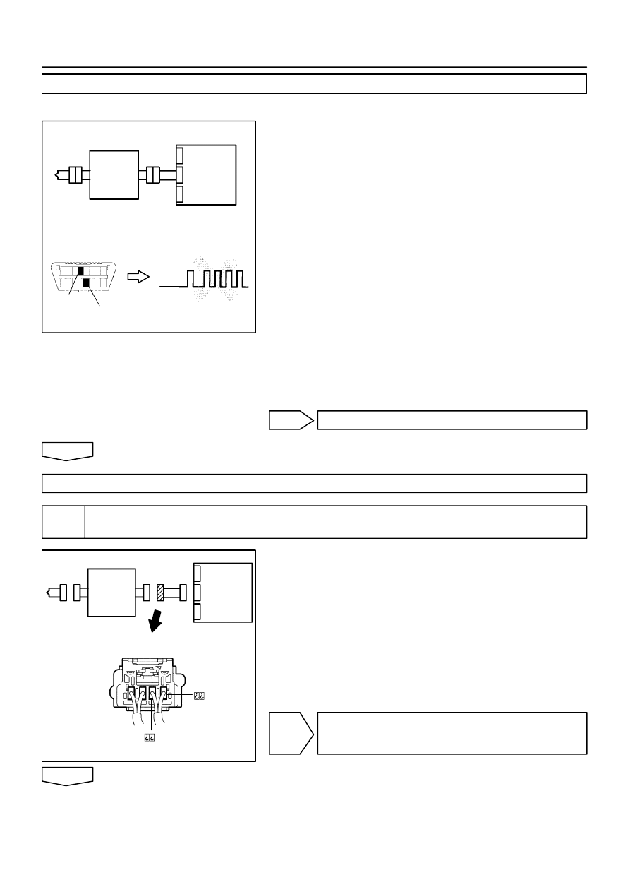
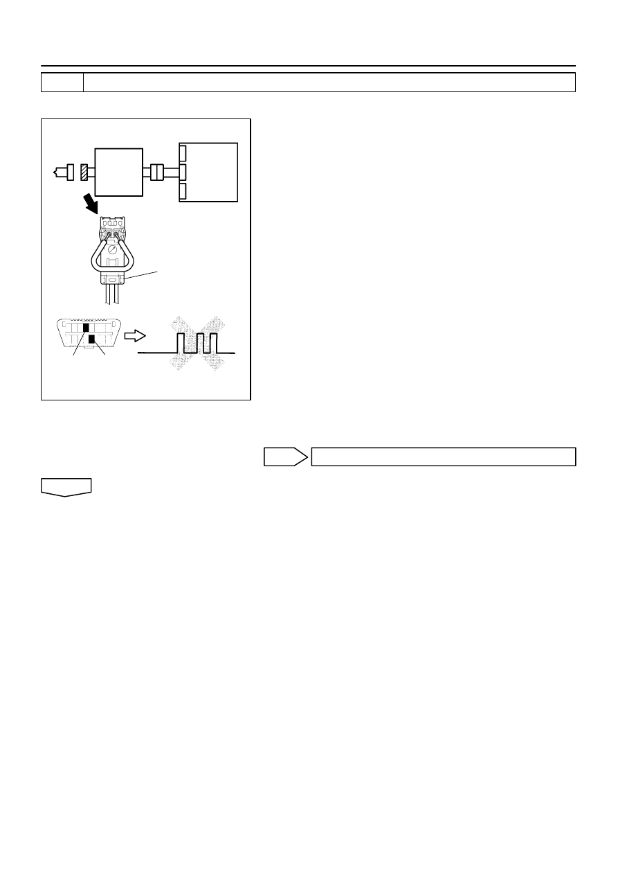
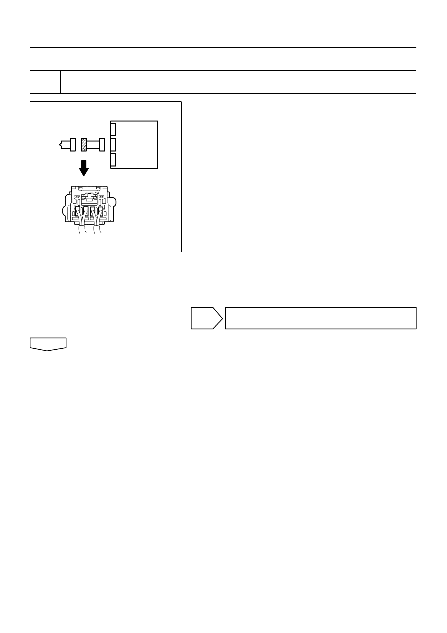
2.
DTC CHECK ( using diagnosis check wire)
(a)
Present troubles codes:
Output the DTC.
(1)
Turn the ignition switch to the ON position and wait
for approx. 60 seconds.
(2)
Using SST, connect terminals Tc and CG of the
DLC3.
SST
09843–18040
NOTICE:
Pay due attention to the terminal connecting position to
avoid a malfunction.
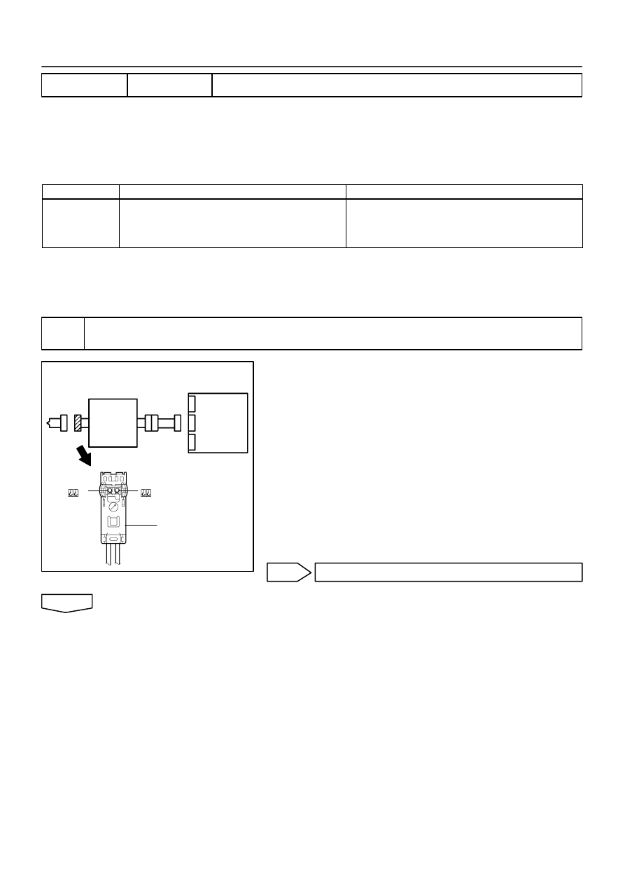
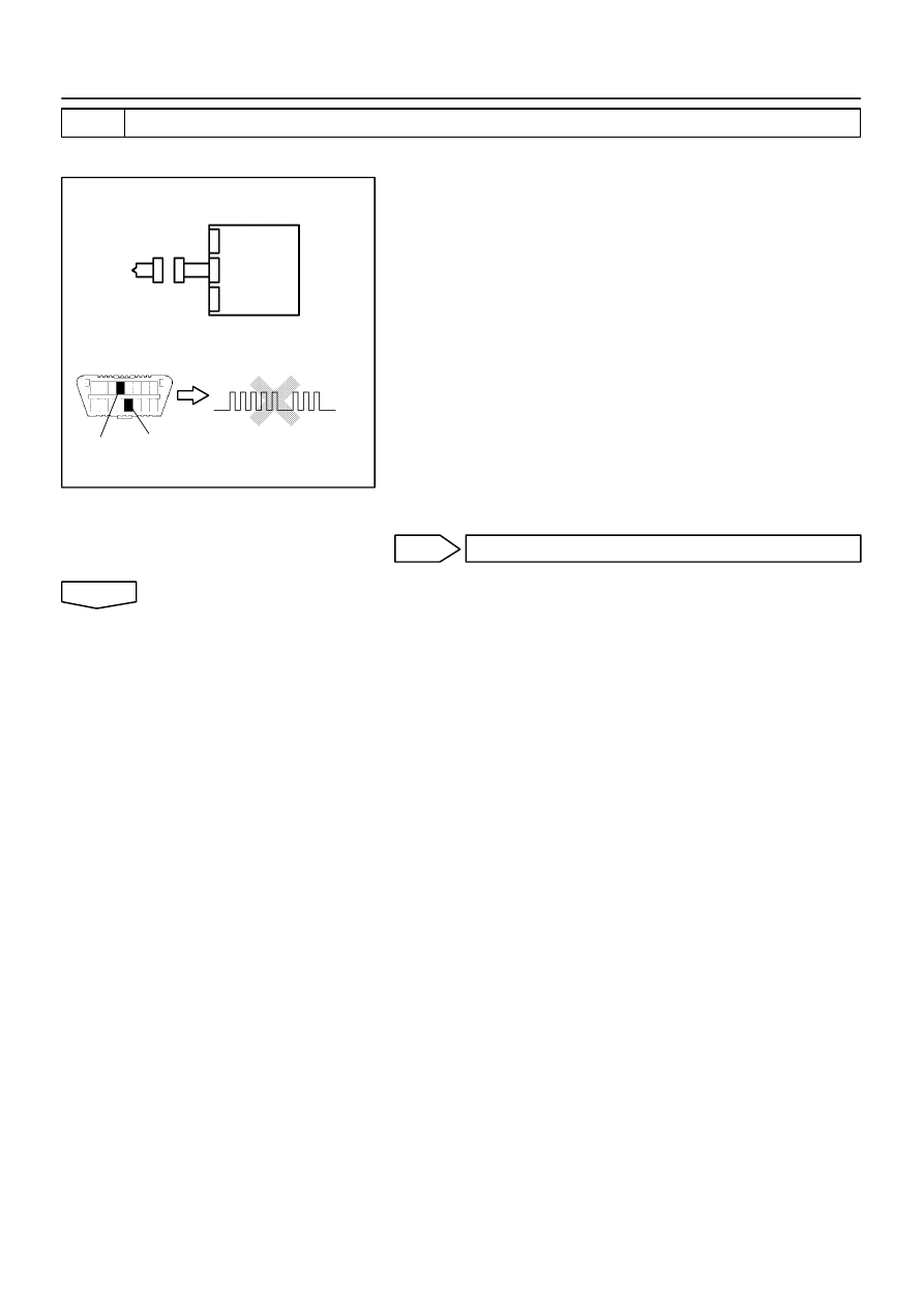
(b)
Past troubles codes:
Output the DTC.
(1)
Using service wire, connect terminals Tc and CG of
the DLC3.
SST
09843–18040
(2)
Turn the ignition switch to the ON position and wait
for approx. 60 seconds.
NOTICE:
Pay due attention to the terminal connecting position to
avoid a malfunction.
H13050
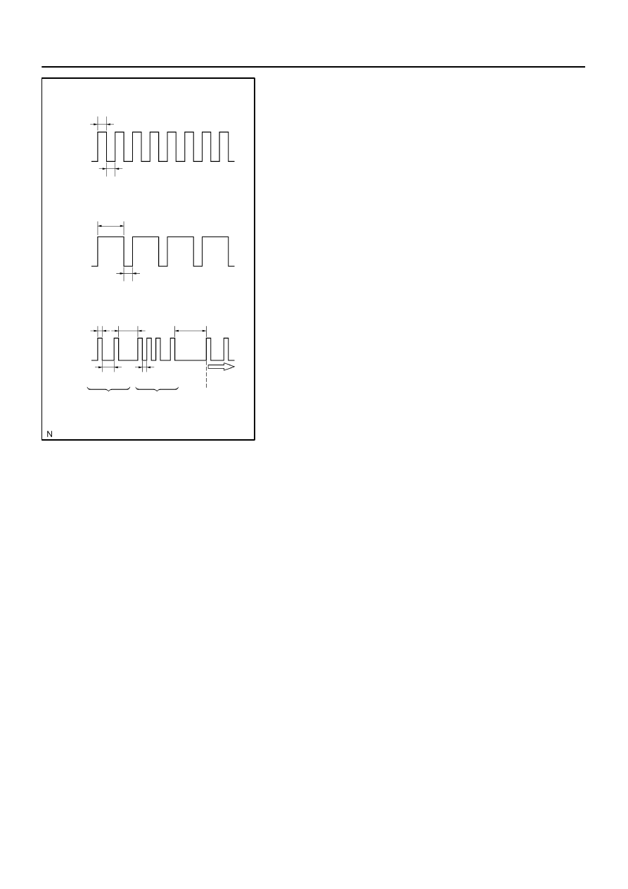
Normal Code (w/o Past Trouble Code)
Normal Code (w/ Past Trouble Code)
Malfunctioning Code
(Example Code 11 and 31)
0.25
ON
OFF
0.75
0.25
0.25
ON
OFF
0.5
2.5
4.0
1.5
0.5
Repeat
DTC31
DTC11
–
DIAGNOSTICS
SUPPLEMENTAL RESTRAINT SYSTEM (April, 2003)
05–425
590
Author:
Date:
2004 COROLLA (RM1037U)
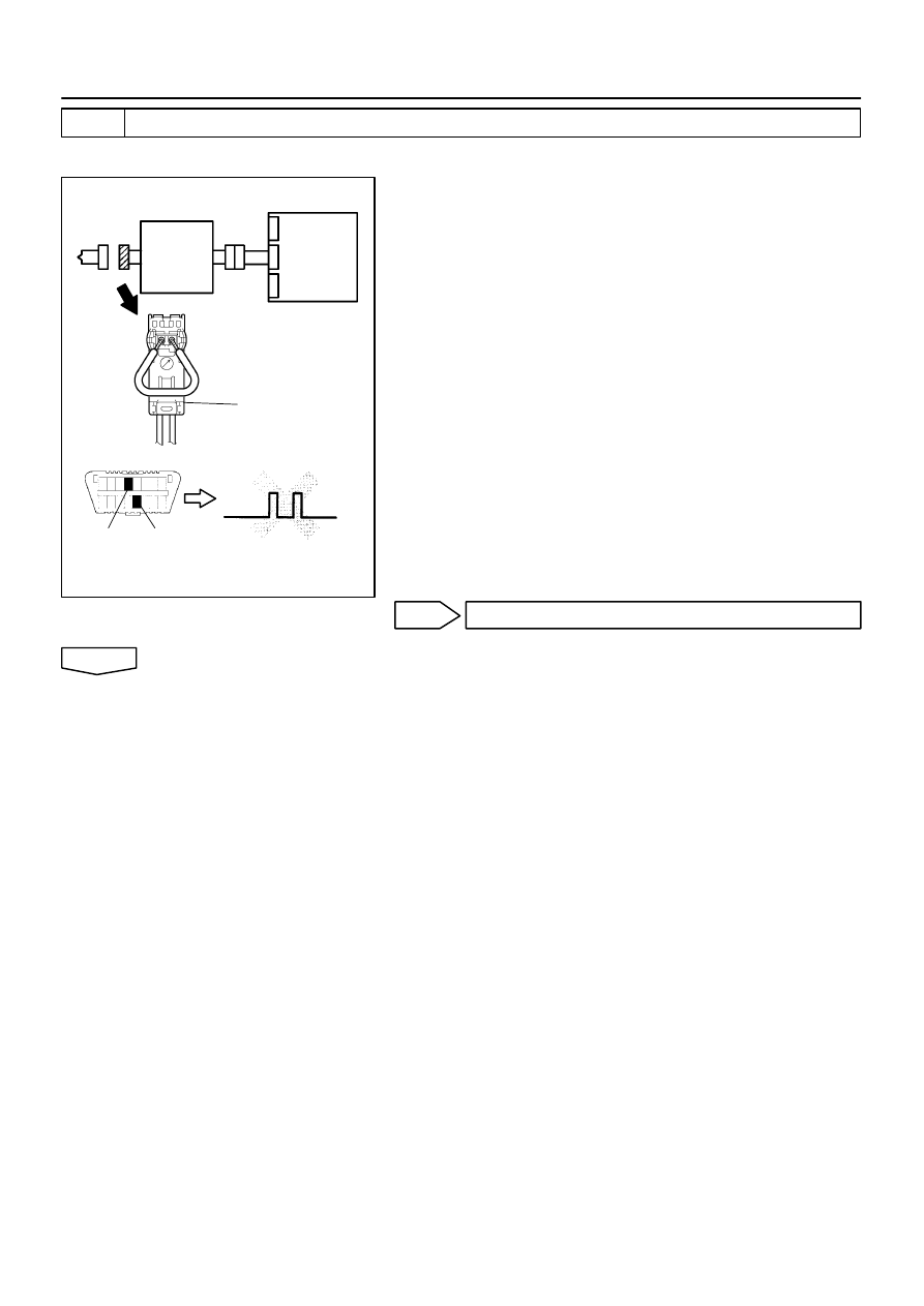
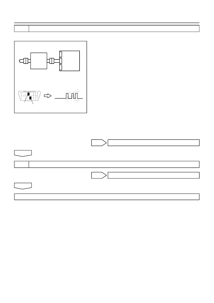
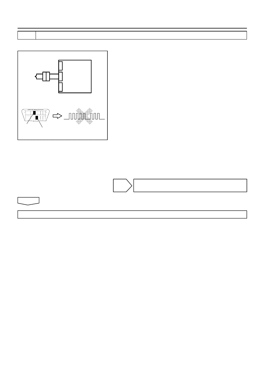
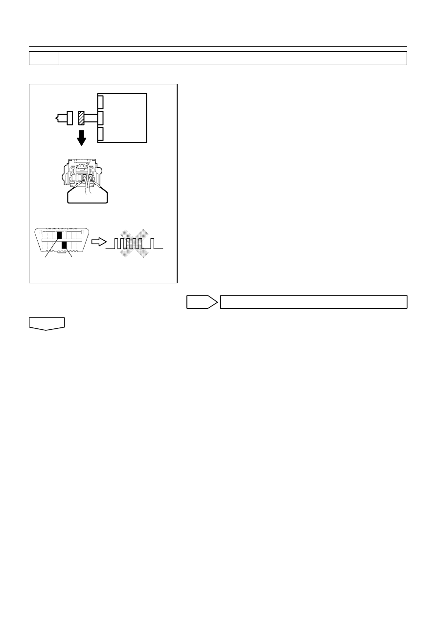
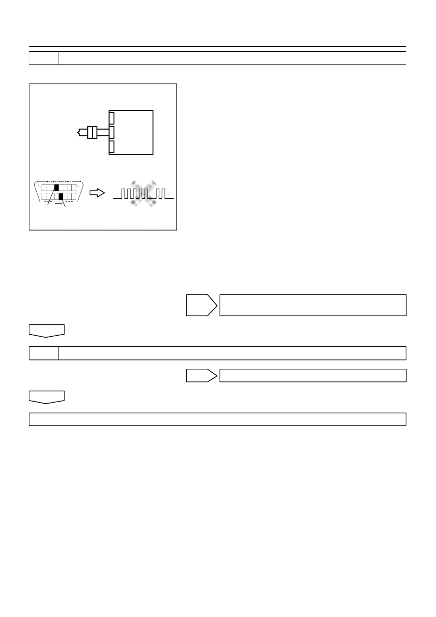
(c)
Read the DTC.
Read the 2–digit DTC as indicated by the number of times
the SRS warning light blinks. As an example, the blinking
patterns, normal, 11 and 31 are shown in the illustration.
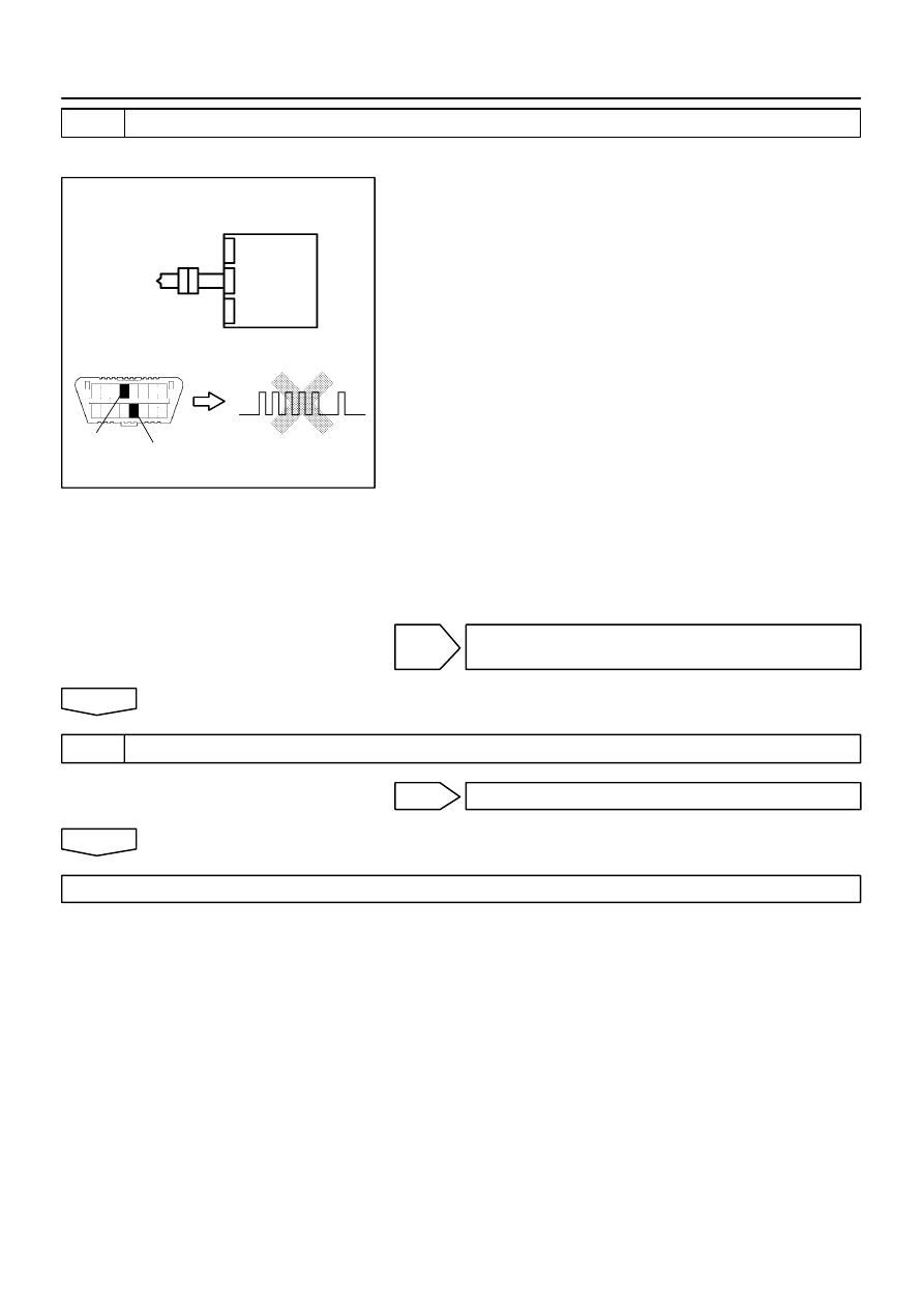
Normal code indication (w/o past trouble
code)
The light will blink 2 times per second.
Normal code indication (w/ past trouble code)
When the past troubles code is stored in the
airbag sensor assembly, the light blinks only
ones a second.
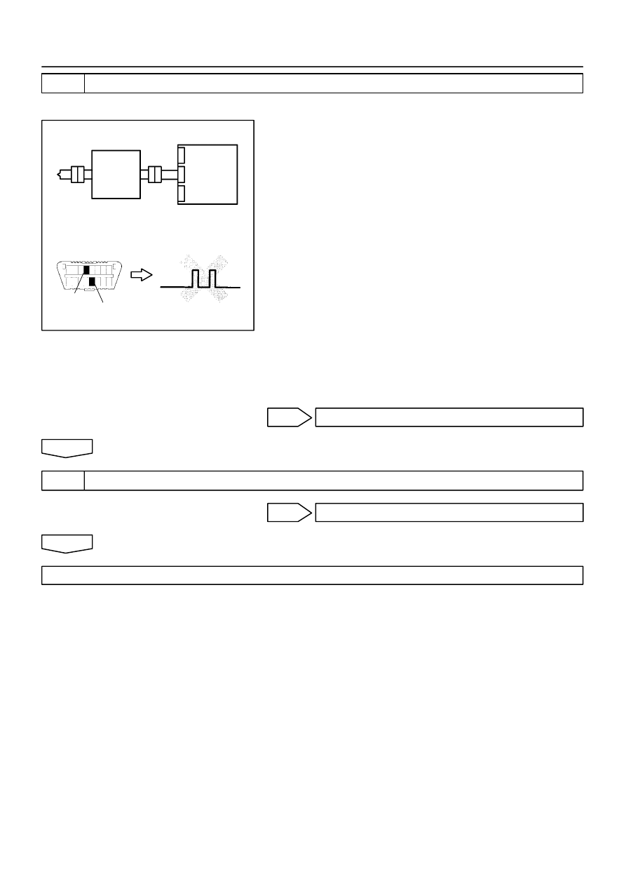
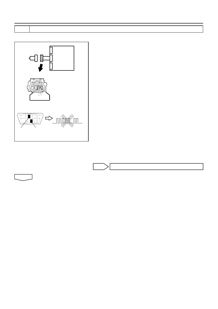
Malfunction code indication
The first blinking output indicates the first digit
of a 2–digit DTC. After a 1.5–second pause,
the second blinking output will indicate the
second digit.
If there are 2 or more codes, there will be a 2.5–second pause
between each code. After all the codes have been output, there
will be a 4.0–second pause and they will all be repeated.
HINT:
In the event of a number of trouble codes, indication will start
from the smallest numbered code.
3.
DTC CHECK (Using hand–held tester)
(a)
Hook up the hand–held tester to the DLC3.
(b)
Read the DTCs by following the prompts on the tester screen.
HINT:
Please refer to the hand–held tester operator’s manual for further details.
4.
DTC CLEARANCE (Not using service wire)
(a)
When the ignition switch is turned off, the diagnostic trouble code is cleared.
HINT:
DTC might not be cleared by turning the ignition switch OFF. In this case, proceed to the next step.
5.
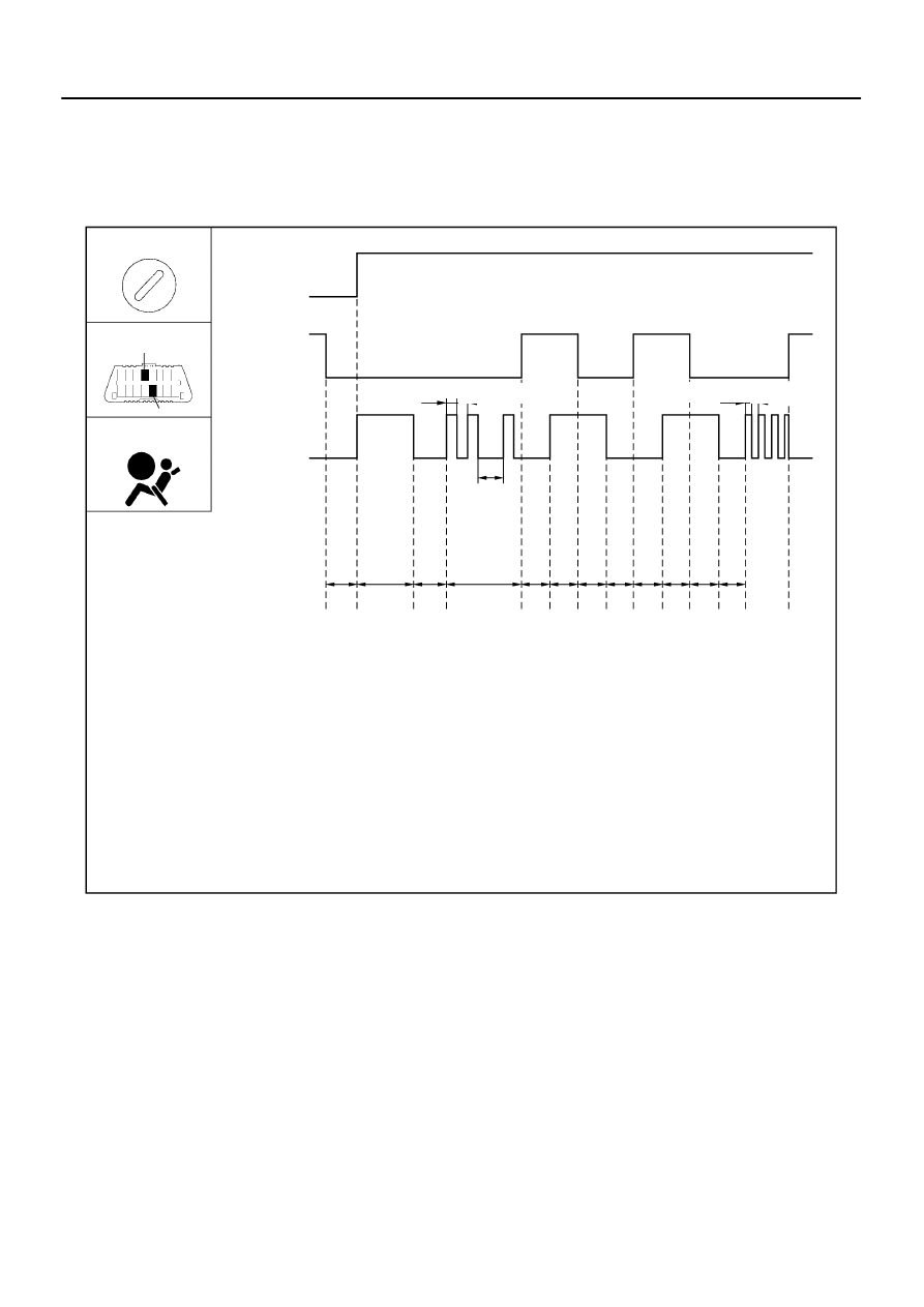
DTC CLEARANCE (Using service wire)
(a)
Using a service wire, connect terminals TC and CG of the DLC3.
(b)
Disconnect terminal TC of DLC3 within 10 seconds after the DTC begins to be output, and check if
the warning light lights up within 3 seconds.
(c)
Within 2.0 seconds to 4.0 seconds after the SRS warning light lights up, connect the terminals TC and
CG of the DLC3.
(d)
Light the SRS warning light goes off 2.0 to 4.0 seconds after connecting the terminals TC and CG of
DLC3, then disconnect the terminal TC of the DLC3 2.0 to 4.0 seconds after the warning light goes
off.
(e)
Light the SRS warning light on again 3 seconds after disconnecting terminal TC of DLC3, then within
2.0 to 4.0 seconds after the lighting, connect terminals TC and CG of the DLC3.
(f)
Check if the SRS warning light goes off 2.0 to 4.0 seconds after connecting terminals TC and CG of
DLC3, and the correct code is output 1 second after the SRS warning goes off.
H41917
T1: 0 –
∞
second
IG S/W
DLC3
SRS Warning
ON
OFF
Open
Short
0.5 sec.
1.5 sec.
T1
0.25 sec.
T2: approx. 6 second
T3: 3 – 5 second
T7: within 1 second
*: The past trouble code in the illustration shows DTC 21 as an example.
T4: 3 – 10 second
T5: 2 – 4 second
T6: 1 – 5 second
T2
T3
T4
T5 T6 T5 T6 T5 T6 T5 T7
0.5 sec.
0.25 sec.
CG
TC
Light (*)
05–426
–
DIAGNOSTICS
SUPPLEMENTAL RESTRAINT SYSTEM (April, 2003)
591
Author:
Date:
2004 COROLLA (RM1037U)
If DTCs are to cleared, repeat the above procedure until the codes are cleared.

–
DIAGNOSTICS
SUPPLEMENTAL RESTRAINT SYSTEM (April, 2003)
05–427
592
Author:
Date:
2004 COROLLA (RM1037U)
6.
DTC CLEARANCE (Using hand–held tester)
(a)
Hook up the hand–held tester to the DLC3.
(b)
Clear the DTCs by following the prompts on the tester screen.
HINT:
Please refer to the hand–held tester operation’s manual for further details.
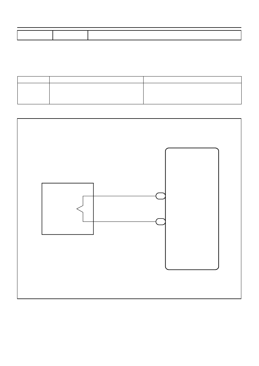
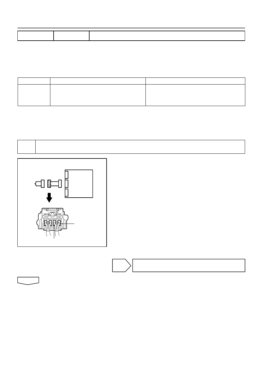
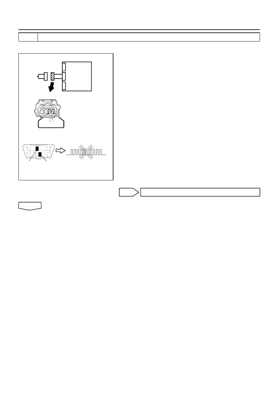
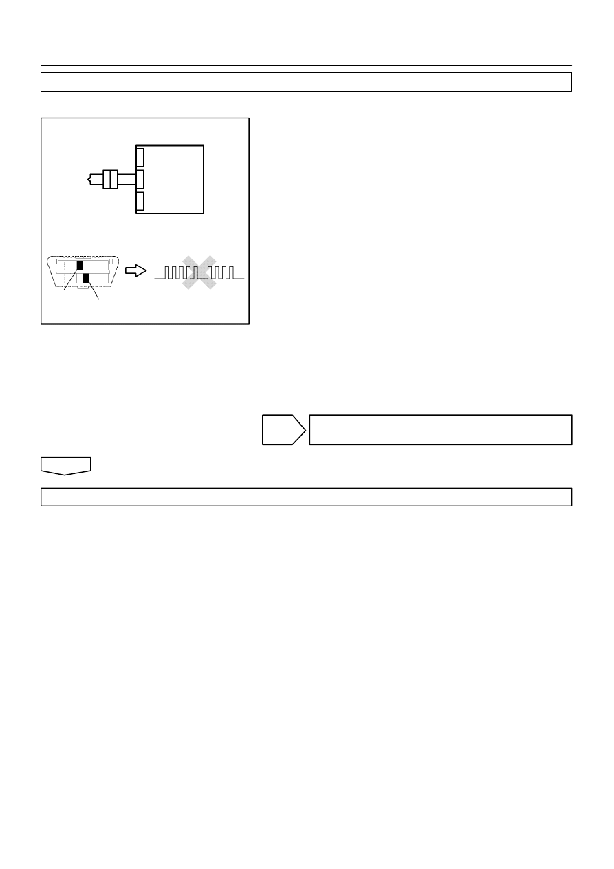
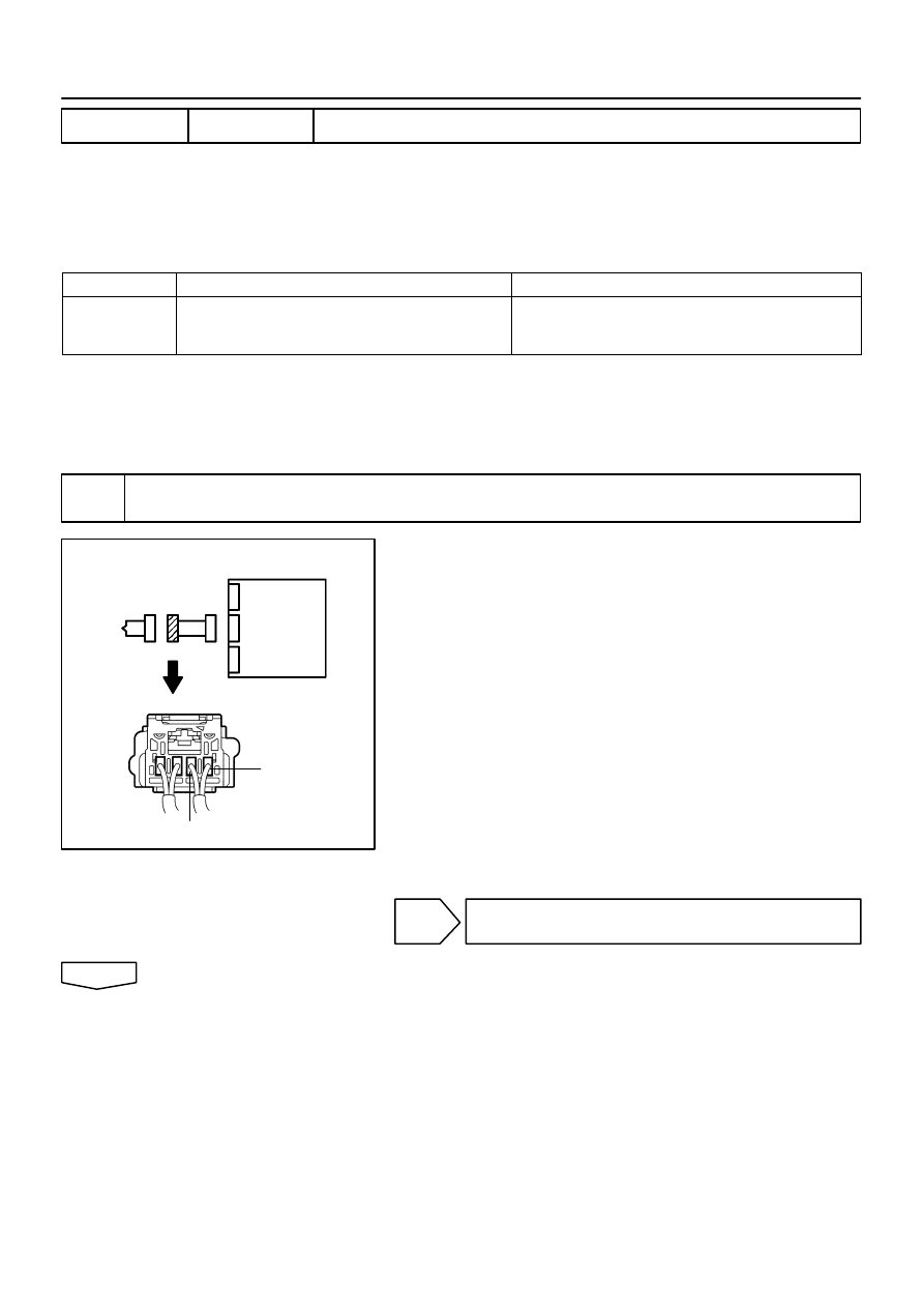
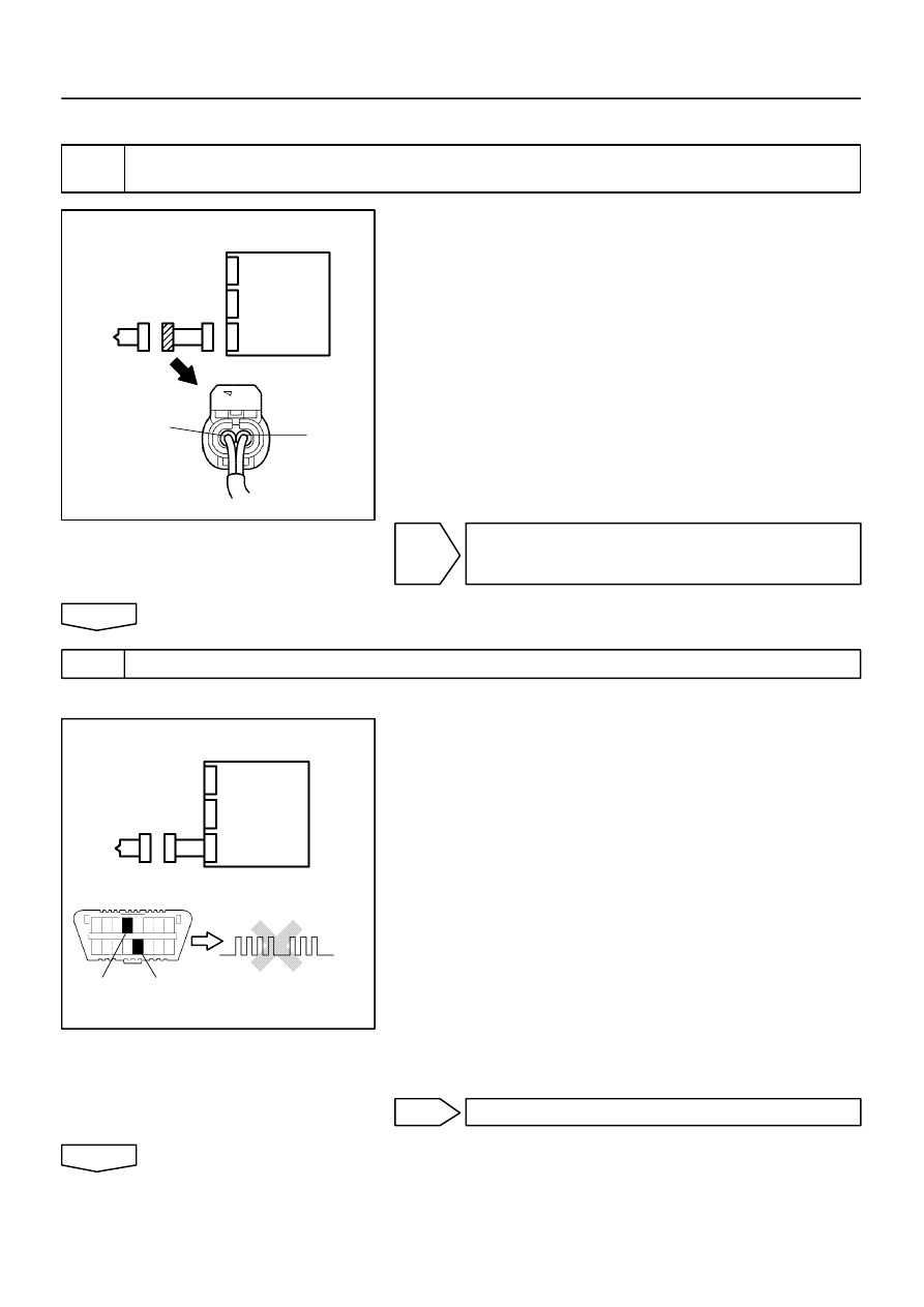
7.
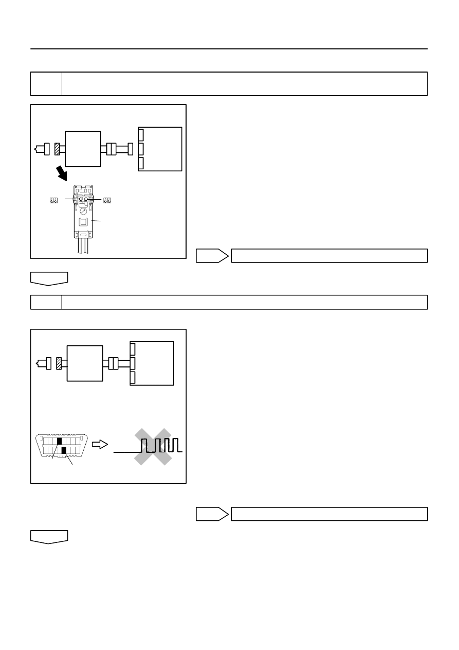
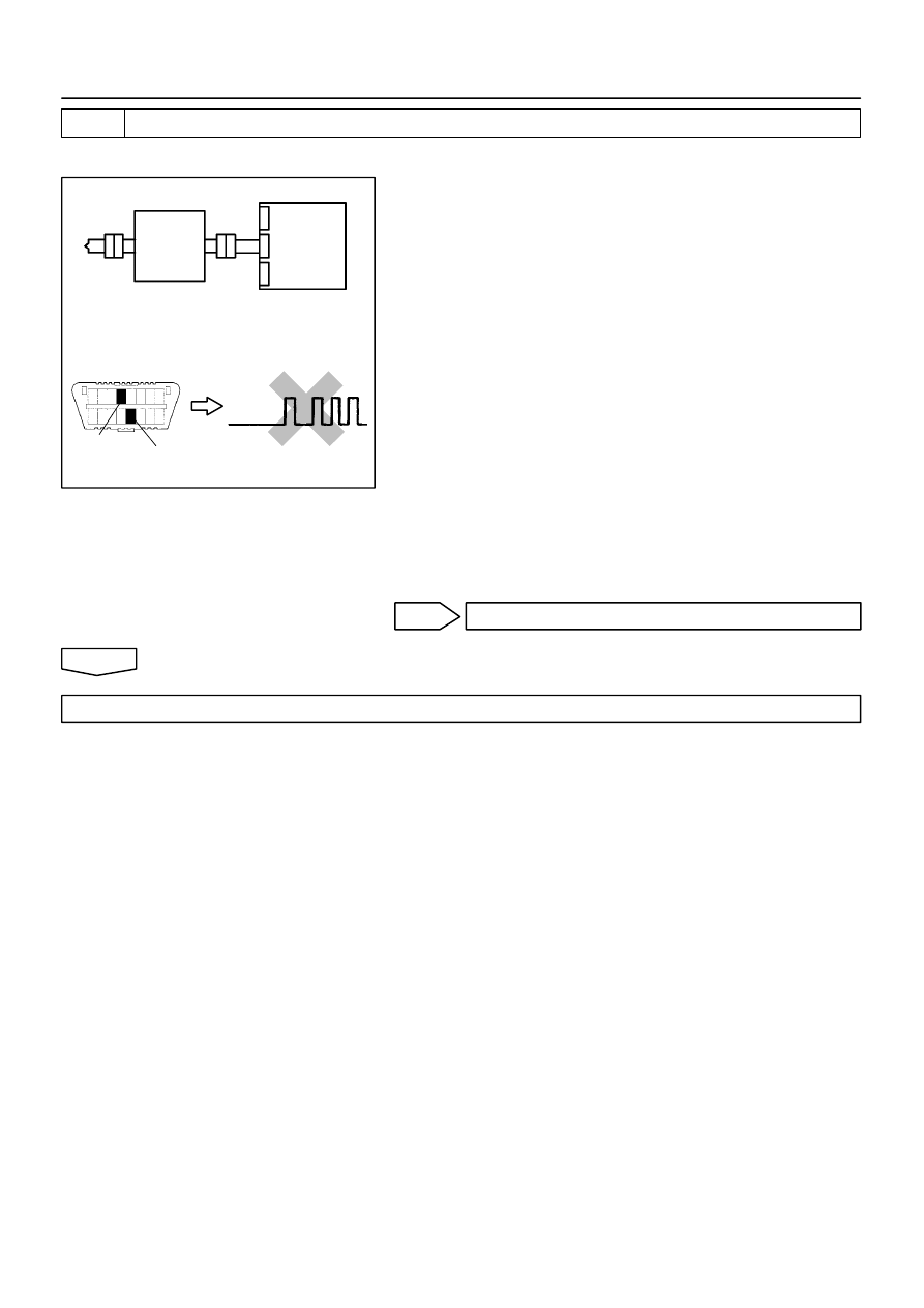
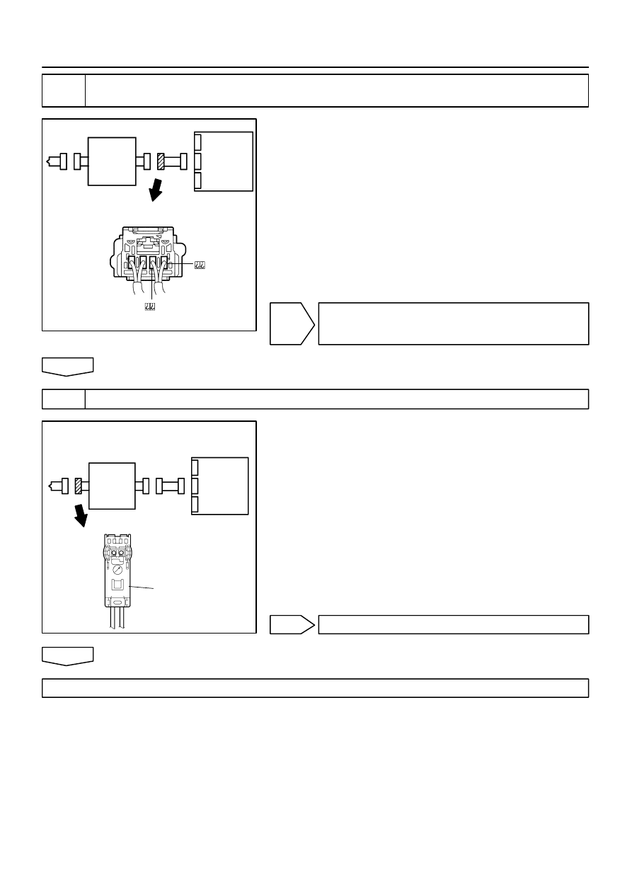
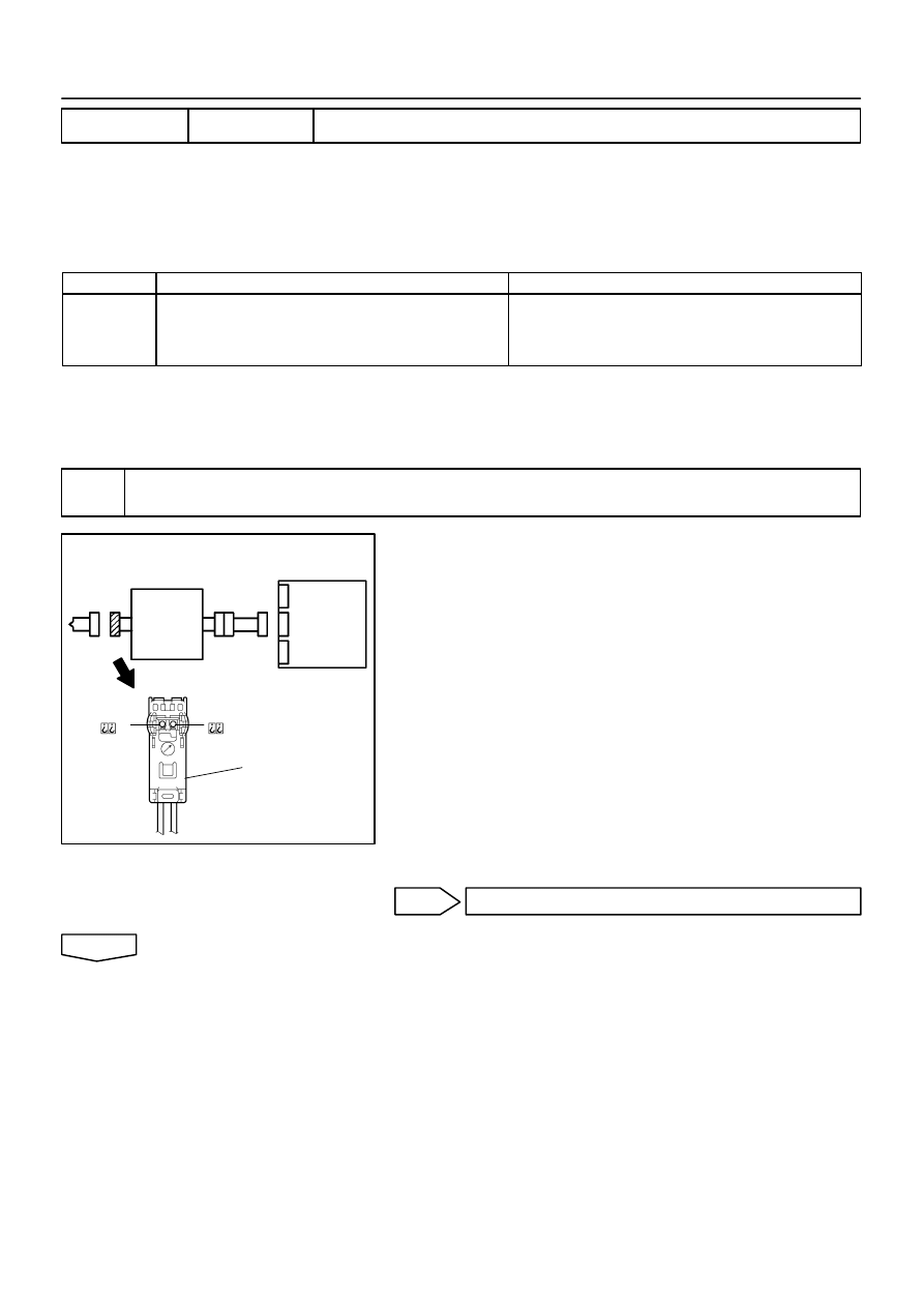
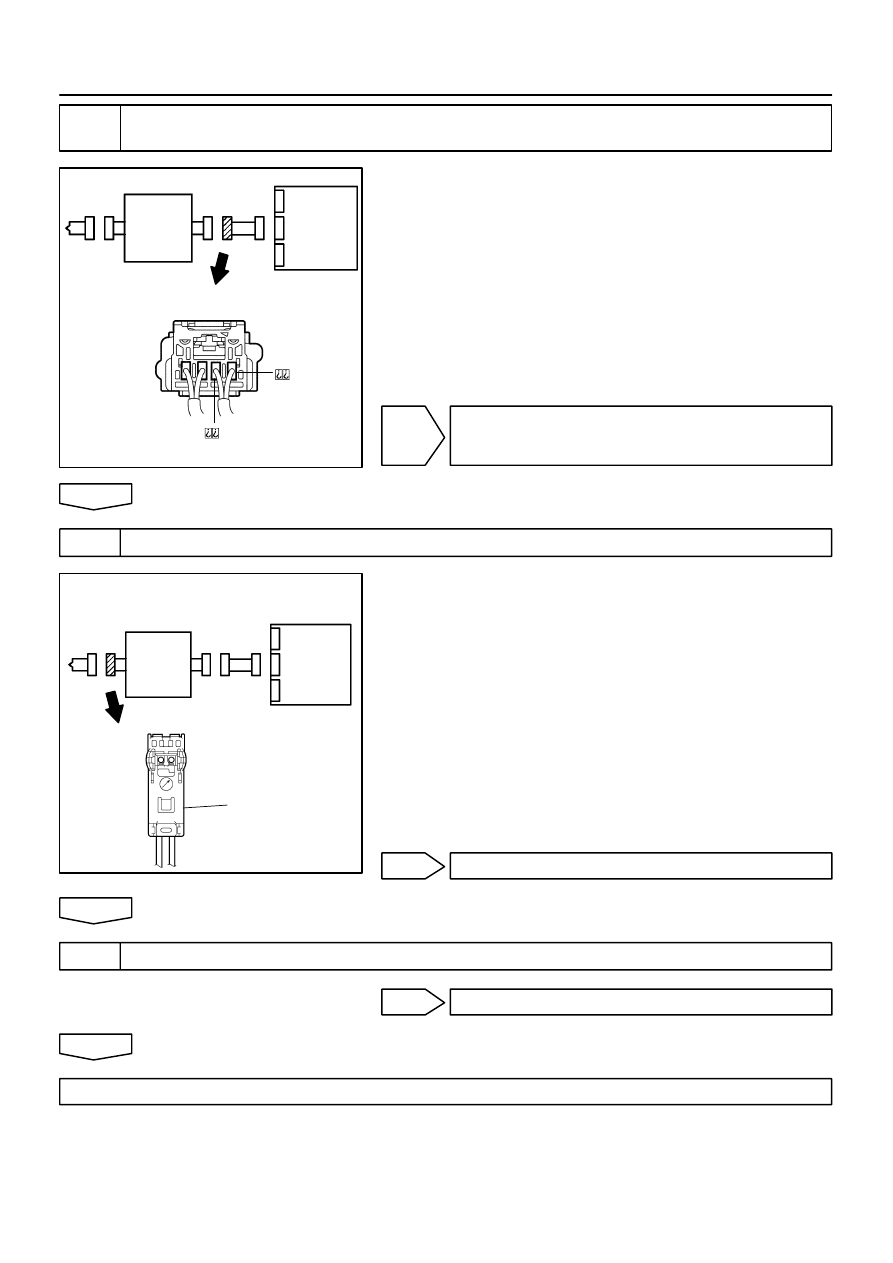
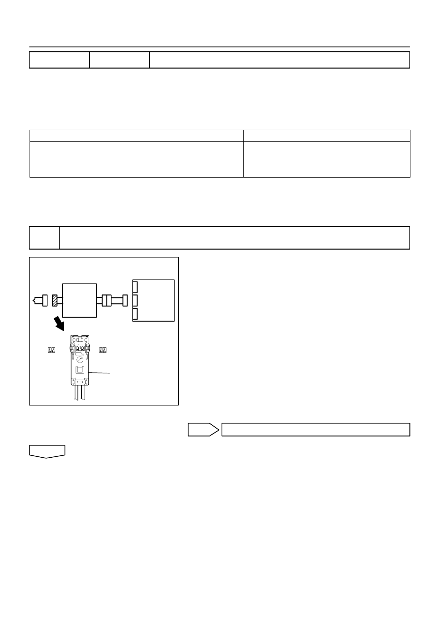
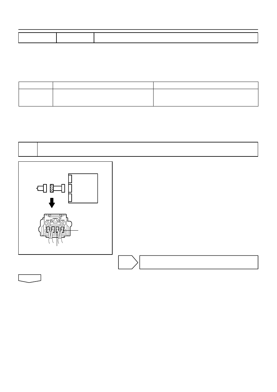
RELEASE METHOD OF AIRBAG ACTIVATION PREVENTION MECHANISM
(a)
An airbag activention prevention mechanism is built into the connector for the squib circuit of the SRS.
When release of the airbag activation prevention mechanism is directed in the troubleshooting proce-
dure, as shown in the illustration of the connectors on the next pages, insert paper which has the same
thickness as the male terminal between the terminal and the short spring.
CAUTION:
Never release the airbag activation prevention mechanism on the squib connector.
NOTICE:
Do not release the airbag activation prevention mechanism unless specifically directed by the
troubleshooting procedure.
If the inserted paper is too thick the terminal and short spring may be damaged, so always use
paper with the same thickness as the male terminal.
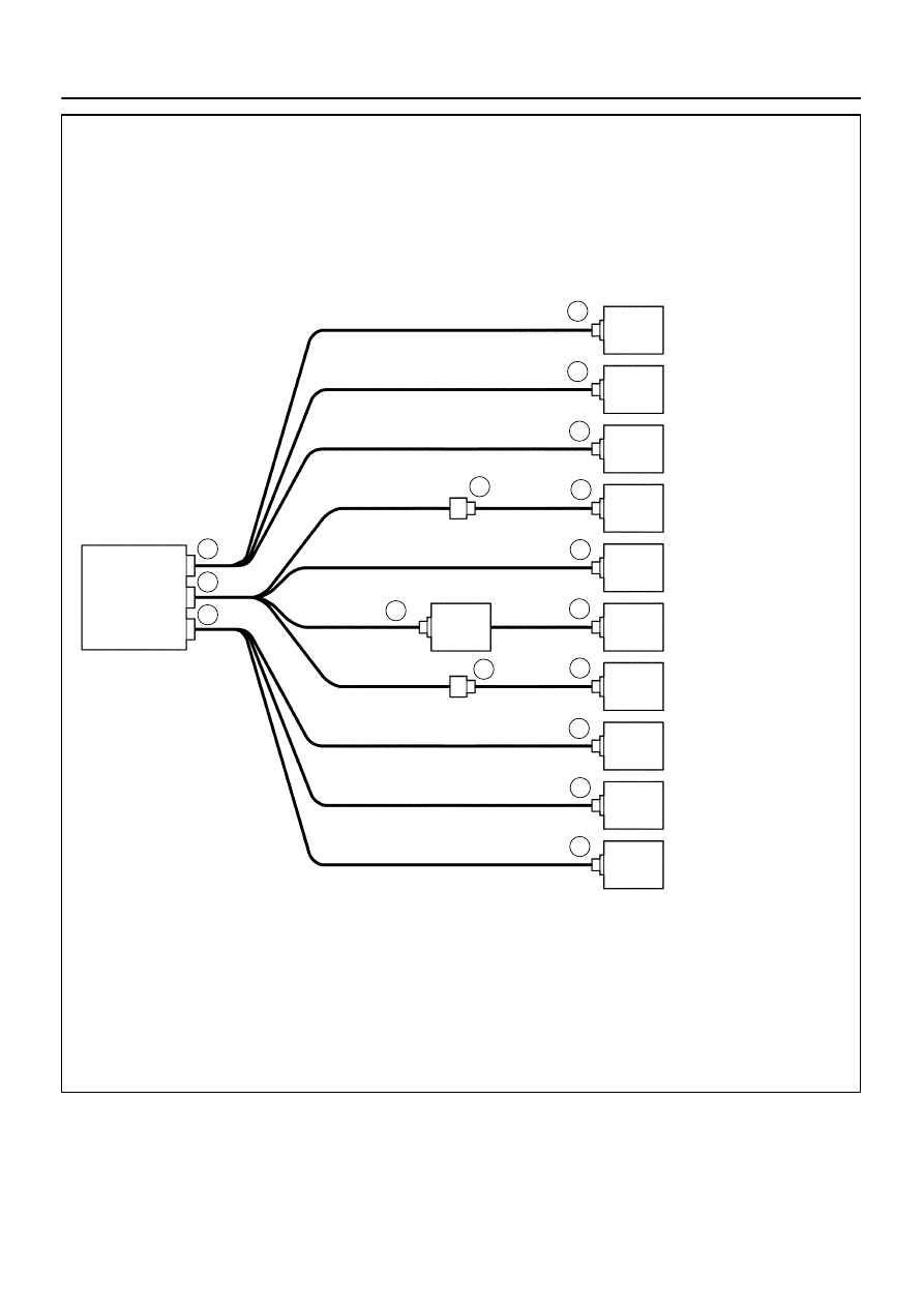
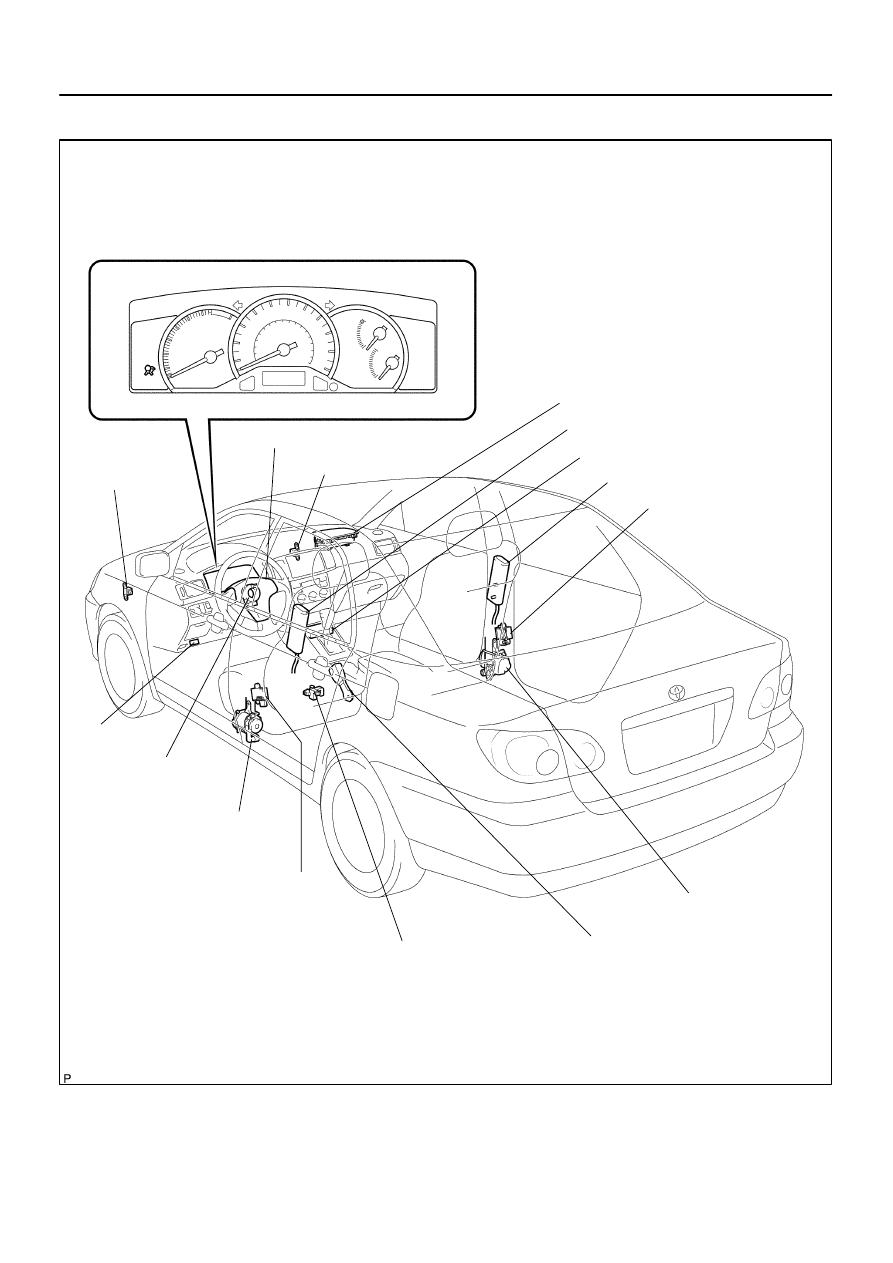
H41916
Airbag
Sensor
Assy Center
Front Airbag Sensor (LH)
Side Airbag
Sensor Assy (LH)
Spiral Cable Sub–Assy
Horn Button
Assy (Squib)
Instrument Panel
Passenger Airbag
Assy (Squib)
Front Seat Airbag
Assy (LH) (Squib)
Seat Belt
Pretensioner (LH)
Front Airbag Sensor (RH)
Seat Belt
Pretensioner (RH)
Front Seat Airbag
Assy (RH) (Squib)
Side Airbag
Sensor Assy (RH)
15
5
6
13
11
9
8
7
10
12
4
14
16
3
1
2
05–428
–
DIAGNOSTICS
SUPPLEMENTAL RESTRAINT SYSTEM (April, 2003)
593
Author:
Date:
2004 COROLLA (RM1037U)
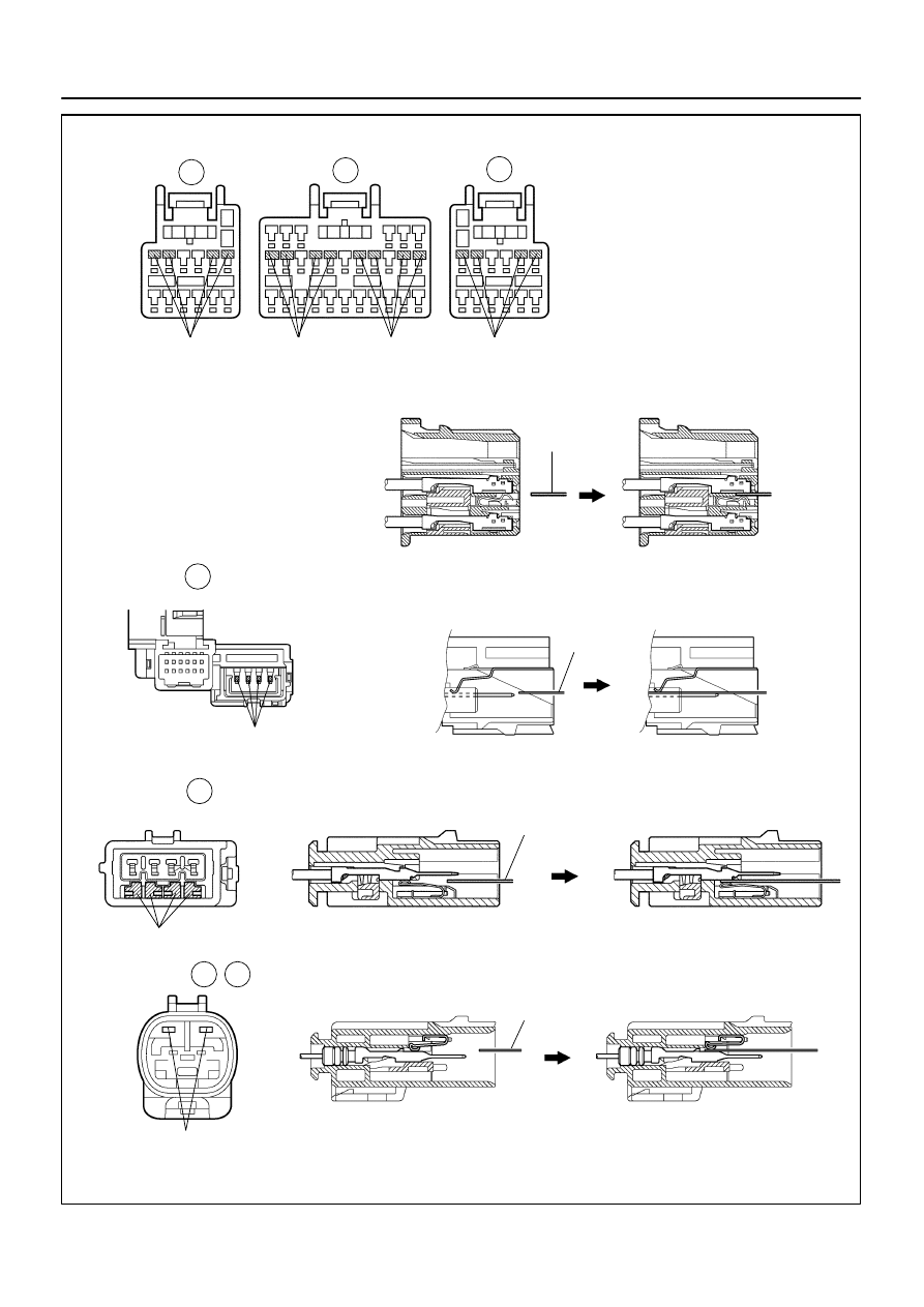
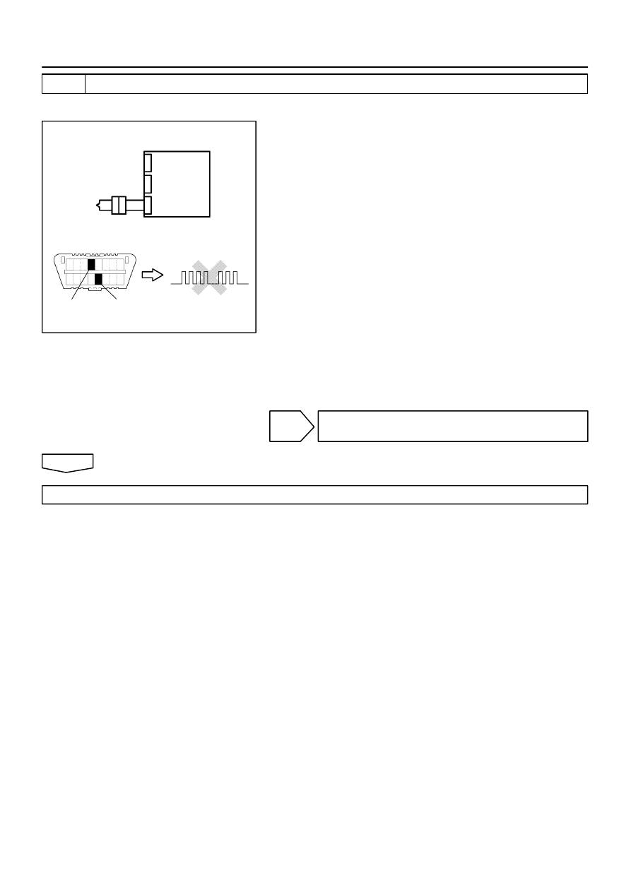
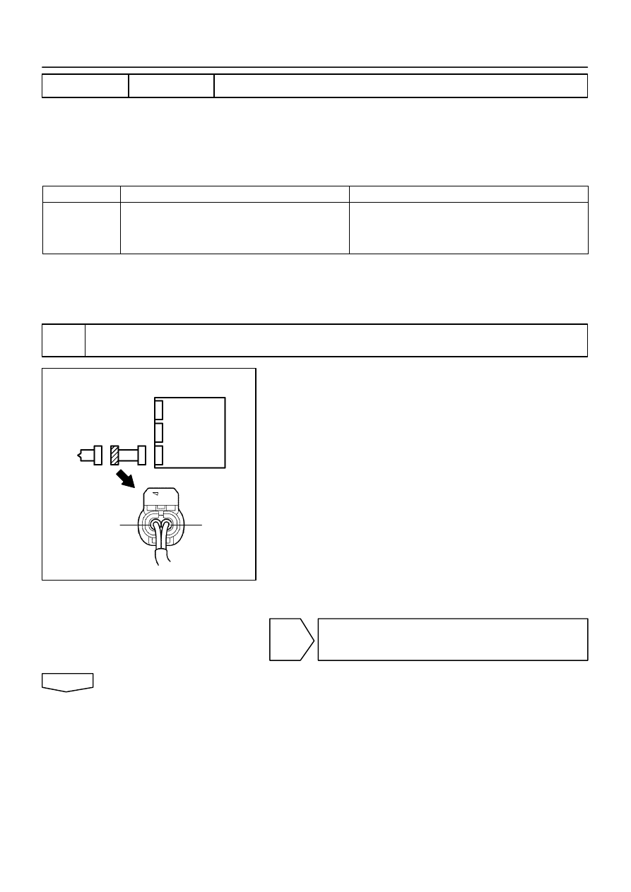
H41995
Airbag Sensor Assy Center Connector
Short Spring
Short Spring
Short Spring
Before Release
After Release
Paper
Before Release
After Release
Paper
Before Release
After Release
Paper
Short Spring
Short Spring
Connector
6
Connector
8
Short Spring
Short Spring
Connector
Before Release
After Release
Paper
1
2
3
4
15
–
DIAGNOSTICS
SUPPLEMENTAL RESTRAINT SYSTEM (April, 2003)
05–429
594
Author:
Date:
2004 COROLLA (RM1037U)

05259–14
05–430
–
DIAGNOSTICS
SUPPLEMENTAL RESTRAINT SYSTEM (April, 2003)
595
Author:
Date:
2004 COROLLA (RM1037U)
DIAGNOSTIC TROUBLE CODE CHART
DTC No.
(See page)
Detection Item
Trouble Area
SRS
Warning Light
B0100/13
(
05–437
)
SHORT IN D SQUIB CIRCUIT
Horn button assy (squib)
Spiral cable sub–assy
Airbag sensor assy center
Instrument panel wire
ON
B0101/14
(
05–441
)
OPEN IN D SQUIB CIRCUIT
Horn button assy (squib)
Spiral cable sub–assy
Airbag sensor assy center
Instrument panel wire
ON
B0102/11
(
05–445
)
SHORT IN D SQUIB CIRCUIT
(TO GROUND)
Horn button assy (squib)
Spiral cable sub–assy
Airbag sensor assy center
Instrument panel wire
ON
B0103/12
(
05–449
)
SHORT IN D SQUIB CIRCUIT
(TO B+)
Horn button assy (squib)
Spiral cable sub–assy
Airbag sensor assy center
Instrument panel wire
ON
B0105/53
(
05–453
)
SHORT IN P SQUIB CIRCUIT
Instrument panel passenger airbag assy (squib)
Airbag sensor assy center
Instrument panel wire
ON
B0106/54
(
05–457
)
OPEN IN P SQUIB CIRCUIT
Instrument panel passenger airbag assy (squib)
Airbag sensor assy center
Instrument panel wire
ON
B0107/51
(
05–460
)
SHORT IN P SQUIB CIRCUIT
(TO GROUND)
Instrument panel passenger airbag assy (squib)
Airbag sensor assy center
Instrument panel wire
ON
B0108/52
(
05–463
)
SHORT IN P SQUIB CIRCUIT
(TO B+)
Instrument panel passenger airbag assy (squib)
Airbag sensor assy center
Instrument panel wire
ON
B0110/43
(
05–466
)
SHORT IN SIDE SQUIB (RH) CIR-
CUIT
Front seat airbag assy RH (squib)
Airbag sensor assy center
Instrument panel wire No.3
Blink
B0111/44
(
05–469
)
OPEN IN SIDE SQUIB (RH) CIRCUIT
Front seat airbag assy RH (squib)
Airbag sensor assy center
Instrument panel wire No.3
Blink
B0112/41
(
05–472
)
SHORT IN SIDE SQUIB (RH)
CIRCUIT (TO GROUND)
Front seat airbag assy RH (squib)
Airbag sensor assy center
Instrument panel wire No.3
Blink
B0113/42
(
05–475
)
SHORT IN SIDE SQUIB (RH)
CIRCUIT (TO B+)
Front seat airbag assy RH (squib)
Airbag sensor assy center
Instrument panel wire No.3
Blink
B0115/47
(
05–478
)
SHORT IN SIDE SQUIB (LH)
CIRCUIT
Front seat airbag assy LH (squib)
Airbag sensor assy center
Instrument panel wire No.3
Blink
B0116/48
(
05–481
)
OPEN IN SIDE SQUIB (LH) CIRCUIT
Front seat airbag assy LH (squib)
Airbag sensor assy center
Instrument panel wire No.3
Blink
B0117/45
(
05–484
)
SHORT IN SIDE SQUIB (LH)
CIRCUIT (TO GROUND)
Front seat airbag assy LH (squib)
Airbag sensor assy center
Instrument panel wire No.3
Blink
B0118/46
(
05–487
)
SHORT IN SIDE SQUIB (LH)
CIRCUIT (TO B+)
Front seat airbag assy LH (squib)
Airbag sensor assy center
Instrument panel wire No.3
Blink
B0126/B0127/
27
(
05–490
)
SEAT BELT BUCKLE SWITCH (LH)
MALFUNCTION
Front seat inner belt assy (LH)
Airbag sensor assy center
Instrument panel wire No.3
ON

–
DIAGNOSTICS
SUPPLEMENTAL RESTRAINT SYSTEM (April, 2003)
05–431
596
Author:
Date:
2004 COROLLA (RM1037U)
B0130/63
(
05–494
)
SHORT IN P/T SQUIB (RH) CIRCUIT
Seat belt pretensioner RH (squib)
Airbag sensor assy center
Instrument panel wire No.3
Blink
B0131/64
(
05–498
)
OPEN IN P/T SQUIB (RH) CIRCUIT
Seat belt pretensioner RH (squib)
Airbag sensor assy center
Instrument panel wire No.3
Blink
B0132/61
(
05–501
)
SHORT IN P/T SQUIB (RH) CIRCUIT
(TO GROUND)
Seat belt pretensioner RH (squib)
Airbag sensor assy center
Instrument panel wire No.3
Blink
B0133/62
(
05–504
)
SHORT IN P/T SQUIB (RH) CIRCUIT
(TO B+)
Seat belt pretensioner RH (squib)
Airbag sensor assy center
Instrument panel wire No.3
Blink
B0135/73
(
05–507
)
SHORT IN P/T SQUIB (LH) CIRCUIT
Seat belt pretensioner LH (squib)
Airbag sensor assy center
Instrument panel wire No.3
Blink
B0136/74
(
05–511
)
OPEN IN P/T SQUIB (LH) CIRCUIT
Seat belt pretensioner LH (squib)
Airbag sensor assy center
Instrument panel wire No.3
Blink
B0137/71
(
05–514
)
SHORT IN P/T SQUIB (LH) CIRCUIT
(TO GROUND)
Seat belt pretensioner LH (squib)
Airbag sensor assy center
Instrument panel wire No.3
Blink
B0138/72
(
05–517
)
SHORT IN P/T SQUIB (LH) CIRCUIT
(TO B+)
Seat belt pretensioner LH (squib)
Airbag sensor assy center
Instrument panel wire No.3
Blink
B1100/31
(
05–520
)
AIRBAG SENSOR ASSY CENTER
MALFUNCTION
Airbag sensor assy center
ON
B1135/24
(
05–522
)
HALF CONNECTION DETECTION
MALFUNCTION
Airbag sensor assy center
ON
B1140/32
(
05–524
)
SIDE AIRBAG SENSOR ASSY (RH)
MALFUNCTION
Airbag sensor assy center
Side Airbag sensor assy RH
Instrument panel wire No.3
Blink
B1141/33
(
05–529
)
SIDE AIRBAG SENSOR ASSY (LH)
MALFUNCTION
Airbag sensor assy center
Side Airbag sensor assy LH
Instrument panel wire No.3
Blink
B1153/25
(
05–534
)
SEAT POSITION AIRBAG SENSOR
ASSY MALFUNCTION
Seat position airbag sensor
Airbag sensor assy center
Instrument panel wire No.3
Wire harness (Seat position airbag sensor – Front seat inner
belt assy)
ON
B1156/B1157
/15
(
05–542
)
FRONT AIRBAG SENSOR (RH)
MALFUNCTION
Airbag front RH sensor
Airbag sensor assy center
Engine room main Instrument panel wire No.3
Instrument panel wire
ON
B1158/B1159
/16
(
05–548
)
FRONT AIRBAG SENSOR (LH)
MALFUNCTION
Airbag sensor front LH
Airbag sensor assy center
Engine room main Instrument panel wire No.3
Instrument panel wire
ON
B1180/17
(
05–554
)
SHORT IN D SQUIB (2ND STEP)
CIRCUIT
Horn button assy (D squib (2nd step))
Spiral cable sub–assy
Airbag sensor assy center
Instrument panel wire No.3
ON
B1181/18
(
05–558
)
OPEN IN D SQUIB (2ND STEP)
CIRCUIT
Horn button assy (D squib (2nd step))
Spiral cable sub–assy
Airbag sensor assy center
Instrument panel wire No.3
ON
B1182/19
(
05–562
)
SHORT IN D SQUIB (2ND STEP)
CIRCUIT (TO GROUND)
Horn button assy (D squib (2nd step))
Spiral cable sub–assy
Airbag sensor assy center
Instrument panel wire No.3
ON

05–432
–
DIAGNOSTICS
SUPPLEMENTAL RESTRAINT SYSTEM (April, 2003)
597
Author:
Date:
2004 COROLLA (RM1037U)
B1183/22
(
05–566
)
SHORT IN D SQUIB (2ND STEP)
CIRCUIT (TO B+)
Horn button assy (D squib (2nd step))
Spiral cable sub–assy
Airbag sensor assy center
Instrument panel wire No.3
ON
B1185/57
(
05–570
)
SHORT IN P SQUIB (2ND STEP)
CIRCUIT
Instrument panel passenger airbag assy (P squib (2nd step))
Airbag sensor assy center
Instrument panel wire
ON
B1186/58
(
05–573
)
OPEN IN P SQUIB (2ND STEP)
CIRCUIT
Instrument panel passenger airbag assy (P squib (2nd step))
Airbag sensor assy center
Instrument panel wire
ON
B1187/55
(
05–576
)
SHORT IN P SQUIB (2ND STEP)
CIRCUIT (TO GROUND)
Instrument panel passenger airbag assy (P squib (2nd step))
Airbag sensor assy center
Instrument panel wire
ON
B1188/56
(
05–579
)
SHORT IN P SQUIB (2ND STEP)
CIRCUIT (TO B+)
Instrument panel passenger airbag assy (P squib (2nd step))
Airbag sensor assy center
Instrument panel wire
ON
Normal
SYSTEM NORMAL
–
OFF
Normal
(
05–582
)
VOLTAGE SOURCE DROP
Battery
Airbag sensor assy center
ON
HINT:
When the SRS warning light remains lit up and the DTC is the normal code, this means a voltage source
drops.
This malfunction is not stored in memory by the Airbag sensor assy center and if the power source
voltage returns to normal, the SRS warning light will automatically go out.
When 2 or more codes are indicated, the codes will be displayed in numeral order starting from the
lowest numbered code.
If a code not listed on the chart is displayed, the Airbag sensor assy center is faulty.
In the case of any malfunction concerning any open circuit, ground short, or B+ short due to any squib,
another malfunction code may not be detected. In this case, correct the malfunction currently being
output, and then perform malfunction diagnosis again. Another malfunction code may then be de-
tected.
0525A–13
H41998
Instrument Panel Passenger Airbag Assy
Airbag Sensor
Front LH
Combination Meter (Warning Light)
Airbag Front RH Sensor
Spiral Cable Sub–Assy
Horn Button Assy (w/ Airbag)
Airbag Sensor Assy Center
Seat Belt Pretensioner RH
Side Airbag Sensor Assy LH
Side Airbag Sensor Assy RH
Seat Belt Pretensioner LH
Front Seat Airbag Assy LH
Front Seat Airbag Assy RH
DLC3
Seat Position Airbag Sensor
Seat Belt Buckle Switch LH
–
DIAGNOSTICS
SUPPLEMENTAL RESTRAINT SYSTEM (April, 2003)
05–433
598
Author:
Date:
2004 COROLLA (RM1037U)
LOCATION
05DQA–01
H40028
A12
A13
A14
05–434
–
DIAGNOSTICS
SUPPLEMENTAL RESTRAINT SYSTEM (April, 2003)
599
Author:
Date:
2004 COROLLA (RM1037U)
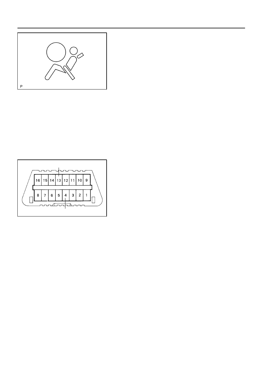
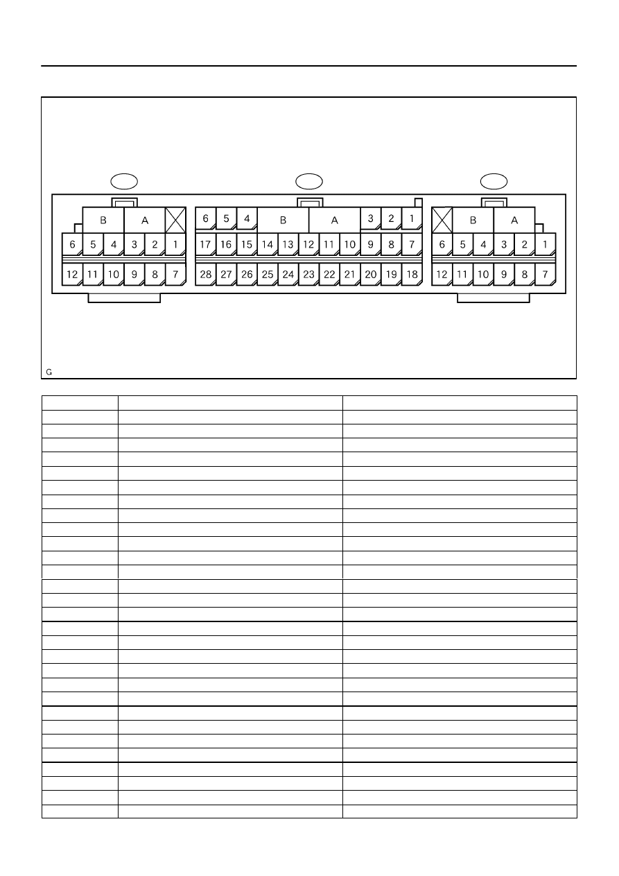
TERMINALS OF ECU
No.
Symbol
Terminal Name
A
–
Electrical Connector Check Mechanism
B
–
Electrical Connector Check Mechanism
A13–3
LA
SRS Warning Light
A13–5
IG2
Power Source (IG2 Fuse)
A13–7
P2–
Squib (Passenger (2 step))
A13–8
P2+
Squib (Passenger (2 step))
A13–9
+SR
Front Airbag Sensor (RH)
A13–10
P+
Squib (Passenger)
A13–11
P–
Squib (Passenger)
A13–12
SIL
Diagnosis
A13–13
D–
Squib (Driver)
A13–14
D+
Squib (Driver)
A13–15
+SL
Airbag Front Sensor (LH)
A13–16
D2+
Squib (Driver (2 step))
A13–17
D2–
Squib (Driver (2 step))
A13–19
Tc
Diagnosis
A13–20
–SR
Airbag Front Sensor (RH)
A13–23
GSW2
ECM
A13–26
–SL
AIrbag Front Sensor (LH)
A13–27
E1
Ground
A13–28
E2
Ground
A12–1
PL–
Squib (Seat Belt Pretensioner, LH)
A12–2
PL+
Squib (Seat Belt Pretensioner, LH)
A12–3
LSP+
Seat Position Sensor
A12–4
LSP–
Seat Position Sensor
A12–5
SFL–
Squib (Side, LH)
A12–6
SFL+
Squib (Side, LH)
A12–7
VUPL
Side Airbag Sensor Assy (LH)
A12–9
SSL–
Side Airbag Sensor Assy (LH)

–
DIAGNOSTICS
SUPPLEMENTAL RESTRAINT SYSTEM (April, 2003)
05–435
600
Author:
Date:
2004 COROLLA (RM1037U)
No.
Terminal Name
Symbol
A12–10
FSL
Side Airbag Sensor Assy (LH)
A12–11
LBE+
Seat Belt Buckle Switch (LH)
A12–12
ESL
Side Airbag Sensor Assy (LH)
A14–1
SFR+
Squib (Side, RH)
A14–2
SFR–
Squib (Side, RH)
A14–5
PR+
Squib (Seat Belt Pretensioner, RH)
A14–6
PR–
Squib (Seat Belt Pretensioner, RH)
A14–7
ESR
Side Airbag Sensor Assy (RH)
A14–9
FSR
Side Airbag Sensor Assy (RH)
A14–10
SSR–
Side Airbag Sensor Assy (RH)
A14–12
VUPR
Side Airbag Sensor Assy (RH)
0525C–13
05–436
–
DIAGNOSTICS
SUPPLEMENTAL RESTRAINT SYSTEM (April, 2003)
601
Author:
Date:
2004 COROLLA (RM1037U)
PROBLEM SYMPTOMS TABLE
HINT:
Proceed with troubleshooting of each circuit in the table below.
Symptom
Suspect Area
See page
When the ignition switch is in the ON position, the SRS warning
light sometimes comes on after approximately 6 seconds.
SRS warning light circuit malfunction
05 585
SRS warning light always comes on even when DTC is not out-
put.
SRS warning light circuit malfunction
(Always lights up, when DTC is not output).
05–585
With the ignition switch is in the ON position, the SRS warning
light does not come on.
SRS warning light circuit malfunction
(Does not light up, when ignition switch is turned to ON).
05–588
Although a SRS warning light operates normally, DTC or a nor-
mal system code is not displayed.
TC terminal circuit
05 590
Although the terminals TC and CG are not connected, DTC or a
normal system code are displayed.
TC terminal circuit
05–590
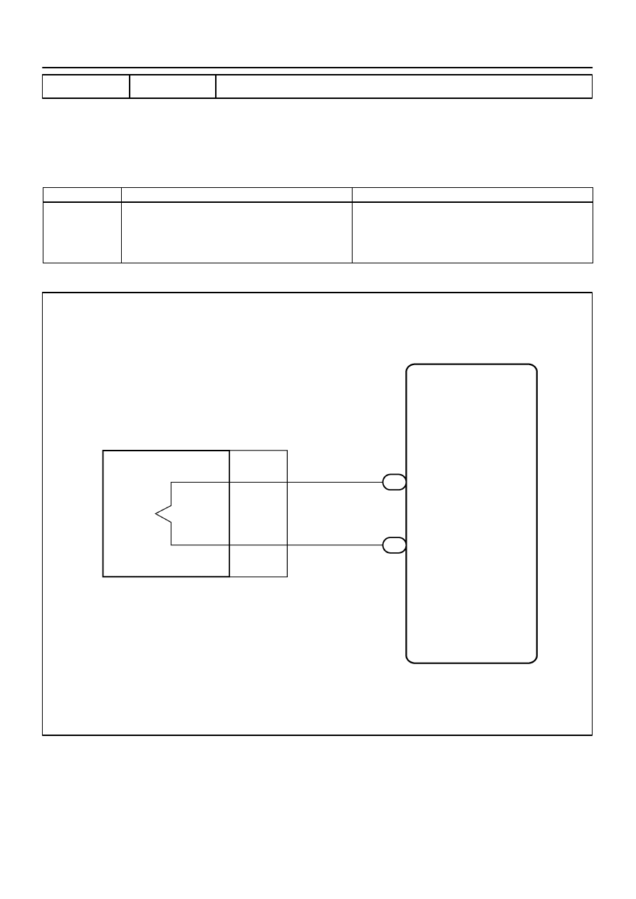
H01451
Airbag Sensor Assy Center
A16
D Squib
Spiral Cable
Sub–Assy
Y
Y–B
D+
D–
1
A13
2
A13
13
14
D+
D–
–
DIAGNOSTICS
SUPPLEMENTAL RESTRAINT SYSTEM (April, 2003)
05–437
602
Author:
Date:
2004 COROLLA (RM1037U)
DTC
B0100/13 SHORT IN D SQUIB CIRCUIT
CIRCUIT DESCRIPTION
The D squib circuit consists of the airbag sensor assy center, spiral cable sub–assy and horn button assy.
It causes the SRS to deploy when the SRS deployment conditions are satisfied.
DTC B0100/13 is recorded when a short is detected in the D squib circuit.
DTC No.
DTC Detecting Condition
Trouble Area
B0100/13
Short circuit between D+ wire harness and D– wire har-
ness of squib
D squib malfunction
Spiral cable sub–assy malfunction
Airbag sensor assy center malfunction
Horn button assy (D squib)
Spiral cable sub–assy
Airbag sensor assy center
Instrument panel wire
WIRING DIAGRAM
055Y1–04
H01001
C91344
H41439
D Squib
Airbag
Sensor
Assy
Center
Spiral
Cable
Sub–Assy
Color: Orange
H01002
H10600 H40103
H40030
D Squib
Airbag
Sensor
Assy
Center
DLC3
CG
Tc
DTC B0100/13
Spiral
Cable
Sub–Assy
05–438
–
DIAGNOSTICS
SUPPLEMENTAL RESTRAINT SYSTEM (April, 2003)
603
Author:
Date:
2004 COROLLA (RM1037U)
INSPECTION PROCEDURE
1
CHECK D SQUIB CIRCUIT(AIRBAG SENSOR ASSY CENTER – HORN BUTTON
ASSY)
(a)
Disconnect the negative (–) terminal cable from the bat-
tery, and wait at least for 90 seconds.
(b)
Disconnect the connectors between the airbag sensor
assy center and the horn button assy.
(c)
Release the airbag activation prevention mechanism of
the connector (on the airbag sensor assy center side) be-
tween the airbag sensor assy center and the spiral cable
sub–assy (See page
05–424
).
(d)
For the connector (on the spiral cable sub–assy side) be-
tween the horn button assy and the spiral cable sub–assy,
measure the resistance between D+ and D–.
OK:
Resistance: 1 M
Ω
or Higher
NG
Go to step 4
OK
2
CHECK AIR BAG SENSOR ASSY CENTER
SST
09843–18040
(a)
Connect the connector to the airbag sensor assy center.
(b)
Connect the negative (–) terminal cable to the battery,
and wait at least for 2 seconds.
(c)
Turn the ignition switch to ON, and wait at least for 20 se-
conds.
(d)
Clear the DTC stored in memory (See page
05–424
).
(e)
Turn the ignition switch to LOCK, and wait at least for 20
seconds.
(f)
Turn the ignition switch to ON, and wait at least for 20 se-
conds.
(g)
Check the DTC (See page
05–424
).
OK:
DTC B0100/13 is not output.
HINT:
Codes other than code B0100/13 may be output at this time, but
they are not relevant to this check.
NG
REPLACE AIR BAG SENSOR ASSY CENTER
OK
H01003
H10600 H40103
H40031
D Squib
Airbag
Sensor
Assy
Center
DLC3
CG
Tc
DTC B0100/13
Spiral
Cable
Sub–Assy
–
DIAGNOSTICS
SUPPLEMENTAL RESTRAINT SYSTEM (April, 2003)
05–439
604
Author:
Date:
2004 COROLLA (RM1037U)
3
CHECK D SQUIB
SST
09843–18040
(a)
Turn the ignition switch to LOCK.
(b)
Disconnect the negative (–) terminal cable from the bat-
tery, and wait at least for 90 seconds.
(c)
Connect the horn button assy connectors.
(d)
Connect the negative (–) terminal cable to the battery,
and wait at least for 2 seconds.
(e)
Turn the ignition switch to ON, and wait at least for 20 se-
conds.
(f)
Clear the DTC stored in memory (See page
05–424
).
(g)
Turn the ignition switch to LOCK, and wait at least for 20
seconds.
(h)
Turn the ignition switch to ON, and wait at least for 20 se-
conds.
(i)
Check the DTC (See page
05–424
).
OK:
DTC B0100/13 is not output.
HINT:
Codes other than code B0100/13 may be output at this time, but
they are not relevant to this check.
NG
REPLACE HORN BUTTON ASSY
OK
USE SIMULATION METHOD TO CHECK
H01004
H41424
H41440
D Squib
Airbag
Sensor
Assy
Center
Spiral
Cable
Sub–Assy
H01000
C91344
H41441
D Squib
Airbag
Sensor
Assy
Center
Spiral
Cable
Sub–Assy
Color: Orange
05–440
–
DIAGNOSTICS
SUPPLEMENTAL RESTRAINT SYSTEM (April, 2003)
605
Author:
Date:
2004 COROLLA (RM1037U)
4
CHECK INSTRUMENT PANEL WIRE(AIRBAG SENSOR ASSY CENTER – SPIRAL
CABLE SUB–ASSY)
(a)
Disconnect the connector of the instrument panel wire.
(b)
Release the airbag activation prevention mechanism of
the connector (on the airbag sensor assy center side) be-
tween the airbag sensor assy center and the spiral cable
sub–assy (See page
05–424
).
(c)
For the connector (on the spiral cable sub–assy side) be-
tween the airbag sensor assy center and the spiral cable
sub–assy, measure the resistance between D+ and D–.
OK:
Resistance: 1 M
Ω
or Higher
NG
REPAIR OR REPLACE INSTRUMENT PANEL
WIRE(AIRBAG SENSOR ASSY CENTER – SPI-
RAL CABLE SUB–ASSY)
OK
5
CHECK SPIRAL CABLE SUB–ASSY
(a)
Release the airbag activation prevention mechanism of
the spiral cable sub–assy connector on the airbag sensor
assy center side (See page
05–424
).
(b)
For the orange connector (on the spiral cable sub–assy
side) between the horn button assy and the spiral cable
sub–assy, measure the resistance between D+ and D–.
OK:
Resistance: 1 M
Ω
or Higher
NG
REPLACE SPIRAL CABLE SUB–ASSY
OK
USE SIMULATION METHOD TO CHECK
H01001
C91344
H41439
D Squib
Airbag
Sensor
Assy
Center
Spiral
Cable
Sub–Assy
Color: Orange
–
DIAGNOSTICS
SUPPLEMENTAL RESTRAINT SYSTEM (April, 2003)
05–441
606
Author:
Date:
2004 COROLLA (RM1037U)
DTC
B0101/14 OPEN IN D SQUIB CIRCUIT
CIRCUIT DESCRIPTION
The D squib circuit consists of the airbag sensor assy center, spiral cable sub–assy and horn button assy.
It causes the SRS to deploy when the SRS deployment conditions are satisfied.
DTC B0101/14 is recorded when an open is detected in the D squib circuit.
DTC No.
DTC Detecting Condition
Trouble Area
B0101/14
Open circuit in D+ wire harness or D– wire harness of squib
D squib malfunction
Spiral cable sub–assy malfunction
Airbag sensor assy center malfunction
Horn button assy (D squib)
Spiral cable sub–assy
Airbag sensor assy center
Instrument panel wire
WIRING DIAGRAM
See page
05–437
.
INSPECTION PROCEDURE
1
CHECK D SQUIB CIRCUIT(AIRBAG SENSOR ASSY CENTER – HORN BUTTON
ASSY)
(a)
Disconnect the negative (–) terminal cable from the bat-
tery, and wait at least for 90 seconds.
(b)
Disconnect the connectors between the horn button assy
and the airbag sensor assy center.
(c)
For the orange connector (on the spiral cable sub–assy
side) between the horn button assy and the spiral cable
sub–assy, measure the resistance between D+ and D–.
OK:
Resistance: Below 1
Ω
NG
Go to step 4
OK
055Y2–04

H01002
H10600
C91348
W02044
H42104
D Squib
Airbag
Sensor
Assy
Center
Spiral
Cable
Sub–Assy
Color: Orange
DLC3
CG
Tc
DTC B0101/14
05–442
–
DIAGNOSTICS
SUPPLEMENTAL RESTRAINT SYSTEM (April, 2003)
607
Author:
Date:
2004 COROLLA (RM1037U)
2
CHECK AIR BAG SENSOR ASSY CENTER
SST
09843–18040
(a)
Connect the connector to the airbag sensor assy center.
(b)
Using a service wire, connect D+ and D– of the orange
connector (on the spiral cable sub–assy side) between
the horn button assy and the spiral cable sub–assy.
(c)
Connect the negative (–) terminal cable to the battery,
and wait at least for 2 seconds.
(d)
Turn the ignition switch to ON, and wait at least for 20 se-
conds.
(e)
Clear the DTC stored in memory (See page
05–424
).
(f)
Turn the ignition switch to LOCK, and wait at least for 20
seconds.
(g)
Turn the ignition switch to ON, and wait at least for 20 se-
conds.
(h)
Check the DTC (See page
05–424
).
OK:
DTC B0101/14 is not output.
HINT:
Codes other than code B0101/14 may be output at this time, but
they are not relevant to this check.
NG
REPLACE AIR BAG SENSOR ASSY CENTER
OK
H01003
H10600 W02044
H40036
D Squib
DLC3
DTC B0101/14
CG
Tc
Airbag
Sensor
Assy
Center
Spiral
Cable
Sub–Assy
H01004
H41424
H41440
D Squib
Airbag
Sensor
Assy
Center
Spiral
Cable
Sub–Assy
–
DIAGNOSTICS
SUPPLEMENTAL RESTRAINT SYSTEM (April, 2003)
05–443
608
Author:
Date:
2004 COROLLA (RM1037U)
3
CHECK D SQUIB
SST
09843–18040
(a)
Turn the ignition switch to LOCK.
(b)
Disconnect the negative (–) terminal cable from the bat-
tery, and wait at least for 90 seconds.
(c)
Connect the horn button assy connector.
(d)
Connect the negative (–) terminal cable to the battery,
and wait at least for 2 seconds.
(e)
Turn the ignition switch to ON, and wait at least for 20 se-
conds.
(f)
Clear the DTC stored in memory (See page
05–424
).
(g)
Turn the ignition switch to LOCK, and wait at least for 20
seconds.
(h)
Turn the ignition switch to ON, and wait at least for 20 se-
conds.
(i)
Check the DTC (See page
05–424
).
OK:
DTC B0101/14 is not output.
HINT:
Codes other than code B0101/14 may be output at this time, but
they are not relevant to this check.
NG
REPLACE HORN BUTTON ASSY
OK
USE SIMULATION METHOD TO CHECK
4
CHECK INSTRUMENT PANEL WIRE(AIRBAG SENSOR ASSY CENTER – SPIRAL
CABLE SUB–ASSY)
(a)
Disconnect the connector of the instrument panel wire.
(b)
For the connector (on the spiral cable sub–assy side) be-
tween the airbag sensor assy center and the spiral cable
sub–assy, measure the resistance between D+ and D–.
OK:
Resistance: Below 1
Ω
NG
REPAIR OR REPLACE INSTRUMENT PANEL
WIRE(AIRBAG SENSOR ASSY CENTER – SPI-
RAL CABLE SUB–ASSY)
OK

H01000
C91344
H41441
D Squib
Airbag
Sensor
Assy
Center
Spiral
Cable
Sub–Assy
Color: Orange
05–444
–
DIAGNOSTICS
SUPPLEMENTAL RESTRAINT SYSTEM (April, 2003)
609
Author:
Date:
2004 COROLLA (RM1037U)
5
CHECK SPIRAL CABLE SUB–ASSY
(a)
For the orange connector (on the spiral cable sub–assy
side) between the horn button assy and the spiral cable
sub–assy, measure the resistance between D+ and D–.
OK:
Resistance: Below 1
Ω
NG
REPLACE SPIRAL CABLE SUB–ASSY
OK
USE SIMULATION METHOD TO CHECK
H01001
C91344
H41439
D Squib
Airbag
Sensor
Assy
Center
Spiral
Cable
Sub–Assy
Color: Orange
–
DIAGNOSTICS
SUPPLEMENTAL RESTRAINT SYSTEM (April, 2003)
05–445
610
Author:
Date:
2004 COROLLA (RM1037U)
DTC
B0102/11 SHORT IN D SQUIB CIRCUIT (TO GROUND)
CIRCUIT DESCRIPTION
The D squib circuit consists of the airbag sensor assy center, spiral cable sub–assy and horn button assy.
It causes the SRS to deploy when the SRS deployment conditions are satisfied.
DTC B0102/11 is recorded when a ground short is detected in the D squib circuit.
DTC No.
DTC Detecting Condition
Trouble Area
B0102/11
Short circuit in D squib wire harness (to ground)
D squib malfunction
Spiral cable sub–assy malfunction
Airbag sensor assy center malfunction
Horn button assy (D squib)
Spiral cable sub–assy
Airbag sensor assy center
Instrument panel wire
WIRING DIAGRAM
See page
05–437
.
INSPECTION PROCEDURE
1
CHECK D SQUIB CIRCUIT(AIRBAG SENSOR ASSY CENTER – HORN BUTTON
ASSY)
(a)
Disconnect the negative (–) terminal cable from the bat-
tery, and wait at least for 90 seconds.
(b)
Disconnect the connectors between the airbag sensor
assy center and the horn button assy.
(c)
For the orange connector (on the spiral cable sub–assy
side) between the horn button assy and the spiral cable
sub–assy, measure the resistance between D+ and body
ground.
OK:
Resistance: 1 M
Ω
or Higher
NG
Go to step 5
OK
0525F–14
H01002
C91348
H10600 W02042
H42105
D Squib
Airbag
Sensor
Assy
Center
Spiral
Cable
Sub–Assy
Color: Orange
DLC3
CG
Tc
DTC B0102/11
05–446
–
DIAGNOSTICS
SUPPLEMENTAL RESTRAINT SYSTEM (April, 2003)
611
Author:
Date:
2004 COROLLA (RM1037U)
2
CHECK AIR BAG SENSOR ASSY CENTER
SST
09843–18040
(a)
Connect the connector to the airbag sensor assy center.
(b)
Using a service wire, connect D+ and D– of the orange
connector (on the spiral cable sub–assy side) between
the horn button assy and the spiral cable sub–assy.
(c)
Connect the negative (–) terminal cable to the battery,
and wait at least for 2 seconds.
(d)
Turn the ignition switch to ON, and wait t least for 20 se-
conds.
(e)
Clear the DTC stored in memory (See page
05–424
).
(f)
Turn the ignition switch to LOCK, and wait at least for 20
seconds.
(g)
Turn the ignition switch to ON, and wait at least for 20 se-
conds.
(h)
Check the DTC (See page
05–424
).
OK:
DTC B0102/11 is not output.
HINT:
Codes other than code B0102/11 may be output at this time, but
they are not relevant to this check.
NG
REPLACE AIR BAG SENSOR ASSY CENTER
OK
H01003
H10600 W02042
H40037
D Squib
DLC3
DTC B0102/11
CG
Tc
Airbag
Sensor
Assy
Center
Spiral
Cable
Sub–Assy
–
DIAGNOSTICS
SUPPLEMENTAL RESTRAINT SYSTEM (April, 2003)
05–447
612
Author:
Date:
2004 COROLLA (RM1037U)
3
CHECK D SQUIB
SST
09843–18040
(a)
Turn the ignition switch to LOCK.
(b)
Disconnect the negative (–) terminal cable from the bat-
tery, and wait at least for 90 seconds.
(c)
Connect the horn button assy connectors.
(d)
Connect the negative (–) terminal cable to the battery,
and wait at least for 2 seconds.
(e)
Turn the ignition switch to ON, and wait at least for 20 se-
conds.
(f)
Clear the DTC stored in memory (See page
05–424
).
(g)
Turn the ignition switch to LOCK, and wait at least for 20
seconds.
(h)
Turn the ignition switch to ON, and wait at least for 20 se-
conds.
(i)
Check the DTC (See page
05–424
).
OK:
DTC B0102/11 is not output.
HINT:
Codes other than code B0102/11 may be output at this time, but
they are not relevant to this check.
NG
REPLACE HORN BUTTON ASSY
OK
4
USE SIMULATION METHOD TO CHECK
NG
Go to step 1
OK
REPLACE ALL SRS COMPONENTS INCLUDING THE WIRE HARNESS
H01004
H41424
H41440
D Squib
Airbag
Sensor
Assy
Center
Spiral
Cable
Sub–Assy
H01000
C91344
H41441
D Squib
Airbag
Sensor
Assy
Center
Spiral
Cable
Sub–Assy
Color: Orange
05–448
–
DIAGNOSTICS
SUPPLEMENTAL RESTRAINT SYSTEM (April, 2003)
613
Author:
Date:
2004 COROLLA (RM1037U)
5
CHECK INSTRUMENT PANEL WIRE(AIRBAG SENSOR ASSY CENTER – SPIRAL
CABLE SUB–ASSY)
(a)
Disconnect the connector of the instrument panel wire.
(b)
For the connector (on the spiral cable sub–assy side) be-
tween the airbag sensor assy center and the spiral cable
sub–assy, measure the resistance between D+ and body
ground.
OK:
Resistance: 1 M
Ω
or Higher
NG
REPAIR OR REPLACE INSTRUMENT PANEL
WIRE(AIRBAG SENSOR ASSY CENTER – SPI-
RAL CABLE SUB–ASSY)
OK
6
CHECK SPIRAL CABLE SUB–ASSY
(a)
For the orange connector (on the spiral cable sub–assy
side) between the horn button assy and the spiral cable
sub–assy, measure the resistance between D+ and body
ground.
OK:
Resistance: 1 M
Ω
or Higher
NG
REPLACE SPIRAL CABLE SUB–ASSY
OK
7
USE SIMULATION METHOD TO CHECK
NG
Go to step 1
OK
REPLACE ALL SRS COMPONENTS INCLUDING THE WIRE HARNESS
H01001
C91344
H41439
D Squib
Airbag
Sensor
Assy
Center
Spiral
Cable
Sub–Assy
Color: Orange
–
DIAGNOSTICS
SUPPLEMENTAL RESTRAINT SYSTEM (April, 2003)
05–449
614
Author:
Date:
2004 COROLLA (RM1037U)
DTC
B0103/12 SHORT IN D SQUIB CIRCUIT (TO B+)
CIRCUIT DESCRIPTION
The D squib circuit consists of the airbag sensor assy center, spiral cable sub–assy and horn button assy.
It causes the SRS to deploy when the SRS deployment conditions are satisfied.
DTC B0103/12 is recorded when a B+ short is detected in the D squib circuit.
DTC No.
DTC Detecting Condition
Trouble Area
B0103/12
Short circuit in D squib wire harness (to B+)
D squib malfunction
Spiral cable sub–assy malfunction
Airbag sensor assy center malfunction
Horn button assy (D squib)
Spiral cable sub–assy
Airbag sensor assy center
Instrument panel wire
WIRING DIAGRAM
See page
05–437
.
INSPECTION PROCEDURE
1
CHECK D SQUIB CIRCUIT(AIRBAG SENSOR ASSY CENTER – HORN BUTTON
ASSY)
(a)
Disconnect the negative (–) terminal cable from the bat-
tery, and wait at least for 90 seconds.
(b)
Disconnect the connectors between the airbag sensor
assy center and the horn button assy.
(c)
Connect the negative (–) terminal cable to the battery,
and wait at least for 2 seconds.
(d)
Turn the ignition switch to ON.
(e)
For the orange connector (on the spiral cable sub–assy
side) between the horn button assy and the spiral cable
sub–assy, measure the voltage between D+ and body
ground.
OK:
Voltage: Below 1 V
NG
Go to step 5
OK
0525G–13
H01002
C91348
H10600 W02043
H42106
D Squib
Airbag
Sensor
Assy
Center
Spiral
Cable
Sub–Assy
Color: Orange
DLC3
CG
Tc
DTC B0103/12
05–450
–
DIAGNOSTICS
SUPPLEMENTAL RESTRAINT SYSTEM (April, 2003)
615
Author:
Date:
2004 COROLLA (RM1037U)
2
CHECK AIR BAG SENSOR ASSY CENTER
SST
09843–18040
(a)
Turn the ignition switch to LOCK.
(b)
Disconnect the negative (–) terminal cable from the bat-
tery, and wait at least for 90 seconds.
(c)
Connect the connector to the airbag sensor assy center.
(d)
Using a service wire, connect D+ and D– of the orange
connector (on the spiral cable sub–assy side) between
the horn button assy and the spiral cable sub–assy.
(e)
Connect the negative (–) terminal cable to the battery,
and wait at least for 2 seconds.
(f)
Turn the ignition switch to ON, and wait at least for 20 se-
conds.
(g)
Clear the DTC stored in memory (See page
05–424
).
(h)
Turn the ignition switch to LOCK, and wait at least for 20
seconds.
(i)
Turn the ignition switch to ON, and wait at least for 60 se-
conds.
(j)
Check the DTC (See page
05–424
).
OK:
DTC B0103/12 is not output.
HINT:
Codes other than code B0103/12 may be output at this time, but
they are not relevant to this check.
NG
REPLACE AIR BAG SENSOR ASSY CENTER
OK
H01003
H10600 W02043
H40038
D Squib
DLC3
DTC B0103/12
CG
Tc
Airbag
Sensor
Assy
Center
Spiral
Cable
Sub–Assy
–
DIAGNOSTICS
SUPPLEMENTAL RESTRAINT SYSTEM (April, 2003)
05–451
616
Author:
Date:
2004 COROLLA (RM1037U)
3
CHECK D SQUIB
SST
09843–18040
(a)
Turn the ignition switch to LOCK.
(b)
Disconnect the negative (–) terminal cable from the bat-
tery, and wait at least for 90 seconds.
(c)
Connect the horn button assy connectors.
(d)
Connect the negative (–) terminal cable to the battery,
and wait at least for 2 seconds.
(e)
Turn the ignition switch to ON, and wait at least for 20 se-
conds.
(f)
Clear the DTC stored in memory (See page
05–424
).
(g)
Turn the ignition switch to LOCK, and wait at least for 20
seconds.
(h)
Turn the ignition switch to ON, and wait at least for 20 se-
conds.
(i)
Check the DTC (See page
05–424
).
OK:
DTC B0103/12 is not output.
HINT:
Codes other than code B0103/12 may be output at this time, but
they are not relevant to this check.
NG
REPLACE HORN BUTTON ASSY
OK
4
USE SIMULATION METHOD TO CHECK
NG
Go to step 1
OK
REPLACE ALL SRS COMPONENTS INCLUDING THE WIRE HARNESS

H01004
H41424
H41440
D Squib
Airbag
Sensor
Assy
Center
Spiral
Cable
Sub–Assy
H01000
C91344
H41441
D Squib
Airbag
Sensor
Assy
Center
Spiral
Cable
Sub–Assy
Color: Orange
05–452
–
DIAGNOSTICS
SUPPLEMENTAL RESTRAINT SYSTEM (April, 2003)
617
Author:
Date:
2004 COROLLA (RM1037U)
5
CHECK INSTRUMENT PANEL WIRE(AIRBAG SENSOR ASSY CENTER – SPIRAL
CABLE SUB–ASSY)
(a)
Turn the ignition switch to LOCK.
(b)
Disconnect the connectors of the instrument panel wire.
(c)
Turn the ignition switch to ON.
(d)
For the connector (on the spiral cable sub–assy side) be-
tween the airbag sensor assy center and the spiral cable
sub–assy, measure the voltage between D+ and body
ground.
OK:
Voltage: Below 1 V
NG
REPAIR OR REPLACE INSTRUMENT PANEL
WIRE(AIRBAG SENSOR ASSY CENTER – SPI-
RAL CABLE SUB–ASSY)
OK
6
CHECK SPIRAL CABLE SUB–ASSY
(a)
For the orange connector (on the spiral cable sub–assy
side) between the horn button assy and the spiral cable
sub–assy, measure the voltage between D+ and body
ground.
OK:
Voltage: Below 1 V
NG
REPLACE SPIRAL CABLE SUB–ASSY
OK
7
USE SIMULATION METHOD TO CHECK
NG
Go to step 1
OK
REPLACE ALL SRS COMPONENTS INCLUDING THE WIRE HARNESS
H01454
A15
P Squib
Airbag Sensor Assy Center
Y–R
Y–G
1
2
10
P+
A13
P–
11
A13
P+
P–
–
DIAGNOSTICS
SUPPLEMENTAL RESTRAINT SYSTEM (April, 2003)
05–453
618
Author:
Date:
2004 COROLLA (RM1037U)
DTC
B0105/53 SHORT IN P SQUIB CIRCUIT
CIRCUIT DESCRIPTION
The P squib circuit consists of the airbag sensor assy center and instrument panel passenger airbag assy.
It causes the SRS to deploy when the SRS deployment conditions are satisfied.
DTC B0105/53 is recorded when a short is detected in the P squib circuit.
DTC No.
DTC Detecting Condition
Trouble Area
B0105/53
Short circuit between P+ wire harness and P– wire
harness of squib.
P squib malfunction
Airbag sensor assy center malfunction
Instrument panel passenger airbag assy (P squib)
Airbag sensor assy center
Instrument panel wire
WIRING DIAGRAM
055Y3–04
R14286
H41424
H41932
P Squib
Airbag
Sensor
Assy
Center
P+
P–
05–454
–
DIAGNOSTICS
SUPPLEMENTAL RESTRAINT SYSTEM (April, 2003)
619
Author:
Date:
2004 COROLLA (RM1037U)
INSPECTION PROCEDURE
1
CHECK P SQUIB CIRCUIT(AIRBAG SENSOR ASSY CENTER – INSTRUMENT
PANEL PASSENGER AIRBAG ASSY)
(a)
Disconnect the negative (–) terminal cable from the bat-
tery, and wait at least for 90 seconds.
(b)
Disconnect the connectors between the airbag sensor
assy center and the instrument panel passenger airbag
assy.
HINT:
Make sure that the connector is not damaged (The lock button
is not disengaged, or the claw of the lock is not deformed or
damaged). If the damage is found, replace the wire harness.
(c)
Release the airbag activation prevention mechanism of
the connector (on the airbag sensor assy center side) be-
tween the airbag sensor assy center and the instrument
panel passenger airbag assy (See page
05–424
).
(d)
For the connector (on the instrument panel passenger air-
bag assy side) between the airbag sensor assy center
and the instrument panel passenger airbag assy, mea-
sure the resistance between P+ and P–.
OK:
Resistance: 1 M
Ω
or Higher
NG
REPAIR OR REPLACE INSTRUMENT PANEL
WIRE
OK
H01023
H10600 H01077
H41933
P Squib
Airbag
Sensor
Assy
Center
DLC3
CG
Tc
DTC B0105/53
–
DIAGNOSTICS
SUPPLEMENTAL RESTRAINT SYSTEM (April, 2003)
05–455
620
Author:
Date:
2004 COROLLA (RM1037U)
2
CHECK AIR BAG SENSOR ASSY CENTER
SST
09843–18040
(a)
Connect the connector to the airbag sensor assy center.
(b)
Connect the negative (–) terminal cable to the battery,
and wait at least for 2 seconds.
(c)
Turn the ignition switch to ON, and wait at least for 20 se-
conds.
(d)
Clear the DTC stored in memory (See page
05–424
).
(e)
Turn the ignition switch to LOCK, and wait at least for 20
seconds.
(f)
Turn the ignition switch to ON, and wait at least for 20 se-
conds.
(g)
Check the DTC (See page
05–424
).
OK:
DTC B0105/53 is not output.
HINT:
Codes other than code B0105/53 may be output at this time, but
they are not relevant to this check.
NG
REPLACE AIR BAG SENSOR ASSY CENTER
OK
H10600 H01077
H01024
H40041
P Squib
DTC B0105/53
DLC3
CG
Tc
Airbag
Sensor
Assy
Center
05–456
–
DIAGNOSTICS
SUPPLEMENTAL RESTRAINT SYSTEM (April, 2003)
621
Author:
Date:
2004 COROLLA (RM1037U)
3
CHECK P SQUIB
SST
09843–18040
(a)
Turn the ignition switch to LOCK.
(b)
Disconnect the negative (–) terminal cable from the bat-
tery, and wait at least for 90 seconds.
(c)
Connect the instrument panel passenger airbag assy
connector.
(d)
Connect the negative (–) terminal cable to the battery,
and wait at least for 2 seconds.
(e)
Turn the ignition switch to ON, and wait at least for 20 se-
conds.
(f)
Clear the DTC stored in memory (See page
05–424
).
(g)
Turn the ignition switch to LOCK, and wait at least for 20
seconds.
(h)
Turn the ignition switch to ON, and wait at least for 20 se-
conds.
(i)
Check the DTC (See page
05–424
).
OK:
DTC B0105/53 is not output.
HINT:
Codes other than code B0105/53 may be output at this time, but
they are not relevant to this check.
NG
REPLACE INSTRUMENT PANEL PASSENGER
AIR BAG ASSY
OK
USE SIMULATION METHOD TO CHECK
R14286
H41424
H41932
P Squib
Airbag
Sensor
Assy
Center
P+
P–
–
DIAGNOSTICS
SUPPLEMENTAL RESTRAINT SYSTEM (April, 2003)
05–457
622
Author:
Date:
2004 COROLLA (RM1037U)
DTC
B0106/54 OPEN IN P SQUIB CIRCUIT
CIRCUIT DESCRIPTION
The P squib circuit consists of the airbag sensor assy center and instrument panel passenger airbag assy.
It causes the SRS to deploy when the SRS deployment conditions are satisfied.
DTC B0106/54 is recorded when an open is detected in the P squib circuit.
DTC No.
DTC Detecting Condition
Trouble Area
B0106/54
Open circuit in P+ wire harness or P– wire harness of
squib
P squib malfunction
Airbag sensor assy center malfunction
Instrument panel passenger airbag assy (P squib)
Airbag sensor assy center
Instrument panel wire
WIRING DIAGRAM
See page
05–453
.
INSPECTION PROCEDURE
1
CHECK P SQUIB CIRCUIT(AIRBAG SENSOR ASSY CENTER – INSTRUMENT
PANEL PASSENGER AIRBAG ASSY)
(a)
Disconnect the negative (–) terminal cable from the bat-
tery, and wait at least for 90 seconds.
(b)
Disconnect the connectors between the airbag sensor
assy center and the instrument panel passenger airbag
assy.
(c)
For the connector (on the instrument panel passenger air-
bag assy side) between the airbag sensor assy center
and the instrument panel passenger airbag assy, mea-
sure the resistance between P+ and P–.
OK:
Resistance: Below 1
Ω
NG
REPAIR OR REPLACE INSTRUMENT PANEL
WIRE
OK
055Y4–04
H01023
H10600 H01078
H16855
H41934
P Squib
Airbag
Sensor
Assy
Center
DLC3
DTC B0106/54
CG
Tc
05–458
–
DIAGNOSTICS
SUPPLEMENTAL RESTRAINT SYSTEM (April, 2003)
623
Author:
Date:
2004 COROLLA (RM1037U)
2
CHECK AIR BAG SENSOR ASSY CENTER
SST
09843–18040
(a)
Connect the connector to the airbag sensor assy center.
(b)
Using a service wire, connect P+ and P– of the connector
(on the instrument panel passenger airbag assy side) be-
tween the airbag sensor assy center and the instrument
panel passenger airbag assy.
(c)
Connect the negative (–) terminal cable to the battery,
and wait at least for 2 seconds.
(d)
Turn the ignition switch to ON, and wait at least for 20 se-
conds.
(e)
Clear the DTC stored in memory (See page
05–424
).
(f)
Turn the ignition switch to LOCK, and wait at least for 20
seconds.
(g)
Turn the ignition switch to ON, and wait at least for 20 se-
conds.
(h)
Check the DTC (See page
05–424
).
OK:
DTC B0106/54 is not output.
HINT:
Codes other than code B0106/54 may be output at this time, but
they are not relevant to this check.
NG
REPLACE AIR BAG SENSOR ASSY CENTER
OK
H10600 H01078
H01024
H40043
DTC B0106/54
DLC3
CG
Tc
Airbag
Sensor
Assy
Center
P Squib
–
DIAGNOSTICS
SUPPLEMENTAL RESTRAINT SYSTEM (April, 2003)
05–459
624
Author:
Date:
2004 COROLLA (RM1037U)
3
CHECK P SQUIB
SST
09843–18040
(a)
Turn the ignition switch to LOCK.
(b)
Disconnect the negative (–) terminal cable from the bat-
tery, and wait at least for 90 seconds.
(c)
Connect the instrument panel passenger airbag assy
connector.
(d)
Connect the negative (–) terminal cable to the battery,
and wait at least for 2 seconds.
(e)
Turn the ignition switch to ON, and wait at least for 20 se-
conds.
(f)
Clear the DTC stored in memory (See page
05–424
).
(g)
Turn the ignition switch to LOCK, and wait at least for 20
seconds.
(h)
Turn the ignition switch to ON, and wait at least for 20 se-
conds.
(i)
Check the DTC (See page
05–424
).
OK:
DTC B0106/54 is not output.
HINT:
Codes other than code B0106/54 may be output at this time, but
they are not relevant to this check.
NG
REPLACE INSTRUMENT PANEL PASSENGER
AIR BAG ASSY
OK
USE SIMULATION METHOD TO CHECK
R14286
H41424
H41932
P Squib
Airbag
Sensor
Assy
Center
P+
P–
05–460
–
DIAGNOSTICS
SUPPLEMENTAL RESTRAINT SYSTEM (April, 2003)
625
Author:
Date:
2004 COROLLA (RM1037U)
DTC
B0107/51 SHORT IN P SQUIB CIRCUIT (TO GROUND)
CIRCUIT DESCRIPTION
The P squib circuit consists of the airbag sensor assy center and instrument panel passenger airbag assy.
It causes the SRS to deploy when the SRS deployment conditions are satisfied.
DTC B0107/51 is recorded when ground short is detected in the P squib circuit.
DTC No.
DTC Detecting Condition
Trouble Area
B0107/51
Short circuit in P squib wire harness (to ground)
P squib malfunction
Airbag sensor assy center malfunction
Instrument panel passenger airbag assy (P squib)
Airbag sensor assy center
Instrument panel wire
WIRING DIAGRAM
See page
05–453
.
INSPECTION PROCEDURE
1
CHECK P SQUIB CIRCUIT(AIRBAG SENSOR ASSY CENTER – INSTRUMENT
PANEL PASSENGER AIRBAG ASSY)
(a)
Disconnect the negative (–) terminal cable from the bat-
tery, and wait at least for 90 seconds.
(b)
Disconnect the connectors between the airbag sensor
assy center and the instrument panel passenger airbag
assy.
(c)
For the connector (on the instrument panel passenger air-
bag assy side) between the airbag sensor assy center
and the instrument panel passenger airbag assy, mea-
sure the resistance between P+ and body ground.
OK:
Resistance: 1 M
Ω
or Higher
NG
REPAIR OR REPLACE INSTRUMENT PANEL
WIRE
OK
0525J–13
H01023
H10600 H01075
H16855
H41977
P Squib
Airbag
Sensor
Assy
Center
DLC3
CG
Tc
DTC B0107/51
–
DIAGNOSTICS
SUPPLEMENTAL RESTRAINT SYSTEM (April, 2003)
05–461
626
Author:
Date:
2004 COROLLA (RM1037U)
2
CHECK AIR BAG SENSOR ASSY CENTER
SST
09843–18040
(a)
Connect the connector to the airbag sensor assy center.
(b)
Using a service wire, connect P+ and P– of the connector
(on the instrument panel passenger airbag assy side) be-
tween the airbag sensor assy center and the instrument
panel passenger airbag assy.
(c)
Connect the negative (–) terminal cable to the battery,
and wait at least for 2 seconds.
(d)
Turn the ignition switch to ON, and wait at least for 20 se-
conds.
(e)
Clear the DTC stored in memory (See page
05–424
).
(f)
Turn the ignition switch to LOCK, and wait at least for 20
seconds.
(g)
Turn the ignition switch to ON, and wait at least for 20 se-
conds.
(h)
Check the DTC (See page
05–424
).
OK:
DTC B0107/51 is not output.
HINT:
Codes other than code B0107/51 may be output at this time, but
they are not relevant to this check.
NG
REPLACE AIR BAG SENSOR ASSY CENTER
OK
H10600
H01024
H01075
H40045
P Squib
DTC B0107/51
DLC3
CG
Tc
Airbag
Sensor
Assy
Center
05–462
–
DIAGNOSTICS
SUPPLEMENTAL RESTRAINT SYSTEM (April, 2003)
627
Author:
Date:
2004 COROLLA (RM1037U)
3
CHECK P SQUIB
SST
09843–18040
(a)
Turn the ignition switch to LOCK.
(b)
Disconnect the negative (–) terminal cable from the bat-
tery, and wait at least for 90 seconds.
(c)
Connect the instrument panel passenger airbag assy
connector.
(d)
Connect the negative (–) terminal cable to the battery,
and wait at least for 2 seconds.
(e)
Turn the ignition switch to ON, and wait at least for 20 se-
conds.
(f)
Clear the DTC stored in memory (See page
05–424
).
(g)
Turn the ignition switch to LOCK, and wait at least for 20
seconds.
(h)
Turn the ignition switch to ON, and wait at least for 20 se-
conds.
(i)
Check the DTC (See page
05–424
).
OK:
DTC B0107/51 is not output.
HINT:
Codes other than code B0107/51 may be output at this time, but
they are not relevant to this check.
NG
REPLACE INSTRUMENT PANEL PASSENGER
AIR BAG ASSY
OK
4
USE SIMULATION METHOD TO CHECK
NG
Go to step 1
OK
REPLACE ALL SRS COMPONENTS INCLUDING THE WIRE HARNESS
R14286
H41424
H41932
P Squib
Airbag
Sensor
Assy
Center
P+
P–
–
DIAGNOSTICS
SUPPLEMENTAL RESTRAINT SYSTEM (April, 2003)
05–463
628
Author:
Date:
2004 COROLLA (RM1037U)
DTC
B0108/52 SHORT IN P SQUIB CIRCUIT (TO B+)
CIRCUIT DESCRIPTION
The P squib circuit consists of the airbag sensor assy center and instrument panel passenger airbag assy.
It causes the SRS to deploy when the SRS deployment conditions are satisfied.
DTC B0108/52 is recorded when a B+ short is detected in the P squib circuit.
DTC No.
DTC Detecting Condition
Trouble Area
B0108/52
Short circuit in P squib wire harness (to B+)
P squib malfunction
Airbag sensor assy center malfunction
Instrument panel passenger airbag assy (P squib)
Airbag sensor assy center
Instrument panel wire
WIRING DIAGRAM
See page
05–453
.
INSPECTION PROCEDURE
1
CHECK P SQUIB CIRCUIT(AIRBAG SENSOR ASSY CENTER – INSTRUMENT
PANEL PASSENGER AIRBAG ASSY)
(a)
Disconnect the negative (–) terminal cable from the bat-
tery, and wait at least for 90 seconds.
(b)
Disconnect the connectors between the airbag sensor
assy center and the instrument panel passenger airbag
assy.
(c)
Connect the negative (–) terminal cable to the battery,
and wait at least for 2 seconds.
(d)
Turn the ignition switch to ON.
(e)
For the connector (on the instrument panel passenger air-
bag assy side) between the airbag sensor assy center
and the instrument panel passenger airbag assy, mea-
sure the voltage between P+ and body ground.
OK:
Voltage: Below 1 V
NG
REPAIR OR REPLACE INSTRUMENT PANEL
WIRE
OK
0525K–13
H01023
H10600 H01076
H16855
H41978
P Squib
Airbag
Sensor
Assy
Center
DTC B0108/52
DLC3
CG
Tc
05–464
–
DIAGNOSTICS
SUPPLEMENTAL RESTRAINT SYSTEM (April, 2003)
629
Author:
Date:
2004 COROLLA (RM1037U)
2
CHECK AIR BAG SENSOR ASSY CENTER
SST
09843–18040
(a)
Turn the ignition switch to LOCK.
(b)
Disconnect the negative (–) terminal cable from the bat-
tery, and wait at least for 90 seconds.
(c)
Connect the connector to the airbag sensor assy center.
(d)
Using a service wire, connect P+ and P– of the connector
(on the instrument panel passenger airbag assy side) be-
tween the airbag sensor assy center and the instrument
panel passenger airbag assy.
(e)
Connect the negative (–) terminal cable to the battery,
and wait at least for 2 seconds.
(f)
Turn the ignition switch to ON, and wait at least for 20 se-
conds.
(g)
Clear the DTC stored in memory (See page
05–424
).
(h)
Turn the ignition switch to LOCK, and wait at least for 20
seconds.
(i)
Turn the ignition switch to ON, and wait at least for 20 se-
conds.
(j)
Check the DTC (See page
05–424
).
OK:
DTC B0108/52 is not output.
HINT:
Codes other than code B0108/52 may be output at this time, but
they are not relevant to this check.
NG
REPLACE AIR BAG SENSOR ASSY CENTER
OK
H10600
H01024
H01076
H40047
P Squib
DLC3
CG
Tc
DTC B0108/52
Airbag
Sensor
Assy
Center
–
DIAGNOSTICS
SUPPLEMENTAL RESTRAINT SYSTEM (April, 2003)
05–465
630
Author:
Date:
2004 COROLLA (RM1037U)
3
CHECK P SQUIB
SST
09843–18040
(a)
Turn the ignition switch to LOCK.
(b)
Disconnect the negative (–) terminal cable from the bat-
tery, and wait at least for 90 seconds.
(c)
Connect the instrument panel passenger airbag assy
connector.
(d)
Connect the negative (–) terminal cable to the battery,
and wait at least for 2 seconds.
(e)
Turn the ignition switch to ON, and wait at least for 20 se-
conds.
(f)
Clear the DTC stored in memory (See page
05–424
).
(g)
Turn the ignition switch to LOCK, and wait at least for 20
seconds.
(h)
Turn the ignition switch to ON, and wait at least for 20 se-
conds.
(i)
Check the DTC (See page
05–424
).
OK:
DTC B0108/52 is not output.
HINT:
Codes other than code B0108/52 may be output at this time, but
they are not relevant to this check.
NG
REPLACE INSTRUMENT PANEL PASSENGER
AIR BAG ASSY
OK
4
USE SIMULATION METHOD TO CHECK
NG
Go to step 1
OK
REPLACE ALL SRS COMPONENTS INCLUDING THE WIRE HARNESS

H01454
S7
Side Squib (RH)
Airbag Sensor Assy Center
SFR+
SFR–
Y–R
Y–G
1
2
2
1
A14
A14
05–466
–
DIAGNOSTICS
SUPPLEMENTAL RESTRAINT SYSTEM (April, 2003)
631
Author:
Date:
2004 COROLLA (RM1037U)
DTC
B0110/43 SHORT IN SIDE SQUIB (RH) CIRCUIT
CIRCUIT DESCRIPTION
The side squib (RH) circuit consists of the airbag sensor assy center and front seat airbag assy (RH).
It causes the SRS to deploy when the SRS deployment conditions are satisfied.
DTC B0110/43 is recorded when a short is detected in the side squib (RH) circuit.
DTC No.
DTC Detecting Condition
Trouble Area
B0110/43
Short circuit between SFR+ wire harness and SFR– wire
harness of squib
Side squib (RH) malfunction
Airbag sensor assy center malfunction
Front seat airbag assy (RH)
Airbag sensor assy center
Instrument panel wire No.3
WIRING DIAGRAM
055Y5–05
H01019
C82598
H40977
Side Squib (RH)
Airbag
Sensor
Assy
Center
SFR+
SFR–
H01020
H10600 H01069
H42111
Side Squib (RH)
Airbag
Sensor
Assy
Center
DLC3
CG
Tc
DTC B0110/43
–
DIAGNOSTICS
SUPPLEMENTAL RESTRAINT SYSTEM (April, 2003)
05–467
632
Author:
Date:
2004 COROLLA (RM1037U)
INSPECTION PROCEDURE
1
CHECK SIDE SQUIB(RH) CIRCUIT(AIRBAG SENSOR ASSY CENTER – FRONT
SEAT AIRBAG ASSY RH)
(a)
Disconnect the negative (–) terminal cable from the bat-
tery, and wait at least for 90 seconds.
(b)
Disconnect the connectors between the front seat airbag
assy (RH) and the airbag sensor assy center.
(c)
Release the airbag activation prevention mechanism of
the connector (on the airbag sensor assy center side) be-
tween the airbag sensor assy center and the front seat
airbag assy (RH) (See page
05–424
).
(d)
For the connector (on the front seat airbag assy side) be-
tween the airbag sensor assy center and the front seat
airbag assy (RH), measure the resistance between SFR+
and SFR–.
OK:
Resistance: 1 M
Ω
or Higher
NG
REPAIR OR REPLACE INSTRUMENT PANEL
WIRE NO.3(AIRBAG SENSOR ASSY CENTER –
FRONT SEAT AIRBAG ASSY RH)
OK
2
CHECK AIR BAG SENSOR ASSY CENTER
SST
09843–18040
(a)
Connect the the connector to the airbag sensor assy cen-
ter.
(b)
Connect the negative (–) terminal cable to the battery,
and wait at least for 2 seconds.
(c)
Turn the ignition switch to ON, and wait at least for 20 se-
conds.
(d)
Clear the DTC stored in memory (See page
05–424
).
(e)
Turn the ignition switch to LOCK, and wait at least for 20
seconds.
(f)
Turn the ignition switch to ON, and wait at least for 20 se-
conds.
(g)
Check the DTC (See page
05–424
).
OK:
DTC B0110/43 is not output.
HINT:
Codes other than code B0110/43 may be output at this time, but
they are not relevant to this check.
NG
REPLACE AIR BAG SENSOR ASSY CENTER
OK
H01021
H10600 H01069
H40979
Side Squib (RH)
DLC3
DTC B0110/43
Tc
CG
Airbag
Sensor
Assy
Center
05–468
–
DIAGNOSTICS
SUPPLEMENTAL RESTRAINT SYSTEM (April, 2003)
633
Author:
Date:
2004 COROLLA (RM1037U)
3
CHECK SIDE SQUIB(RH)
SST
09843–18040
(a)
Turn the ignition switch to LOCK.
(b)
Disconnect the negative (–) terminal cable from the bat-
tery, and wait at least for 90 seconds.
(c)
Connect the front seat airbag assy (RH) connector.
(d)
Connect the negative (–) terminal cable to the battery,
and wait at least for 2 seconds.
(e)
Turn the ignition switch to ON, and wait at least for 20 se-
conds.
(f)
Clear the DTC stored in memory (See page
05–424
).
(g)
Turn the ignition switch to LOCK, and wait at least for 20
seconds.
(h)
Turn the ignition switch to ON, and wait at least for 20 se-
conds.
(i)
Check the DTC (See page
05–424
).
OK:
DTC B0110/43 is not output.
HINT:
Codes other than code B0110/43 may be output at this time, but
they are not relevant to this check.
NG
REPLACE SEPARATE TYPE FRONT SEAT
BACK ASSY
OK
USE SIMULATION METHOD TO CHECK
H01019
C82598
H40977
Side Squib (RH)
Airbag
Sensor
Assy
Center
SFR+
SFR–
–
DIAGNOSTICS
SUPPLEMENTAL RESTRAINT SYSTEM (April, 2003)
05–469
634
Author:
Date:
2004 COROLLA (RM1037U)
DTC
B0111/44 OPEN IN SIDE SQUIB (RH) CIRCUIT
CIRCUIT DESCRIPTION
The side squib (RH) circuit consists of the airbag sensor assy center and front seat airbag assy (RH).
It causes the SRS to deploy when the SRS deployment conditions are satisfied.
DTC B0111/44 is recorded when an open is detected in the side squib (RH) circuit.
DTC No.
DTC Detecting Condition
Trouble Area
B0111/44
Open circuit in SFR+ wire harness or SFR– wire harness
of squib
Side squib (RH) malfunction
Airbag sensor assy center malfunction
Front seat airbag assy (RH)
Airbag sensor assy center
Instrument panel wire No.3
WIRING DIAGRAM
See page
05–466
.
INSPECTION PROCEDURE
1
CHECK SIDE SQUIB(RH) CIRCUIT(AIRBAG SENSOR ASSY CENTER – FRONT
SEAT AIRBAG ASSY RH)
(a)
Disconnect the negative (–) terminal cable from the bat-
tery, and wait at least for 90 seconds.
(b)
Disconnect the connectors between the airbag sensor
assy center and the front seat airbag assy (RH).
(c)
For the connector (on the front seat airbag assy
side) be-
tween the airbag sensor assy center and the front seat
airbag assy (RH), measure the resistance between SFR+
and SFR–.
OK:
Resistance: Below 1
Ω
NG
REPAIR OR REPLACE INSTRUMENT PANEL
WIRE NO.3(AIRBAG SENSOR ASSY CENTER –
FRONT SEAT AIRBAG ASSY RH)
OK
055Y9–04
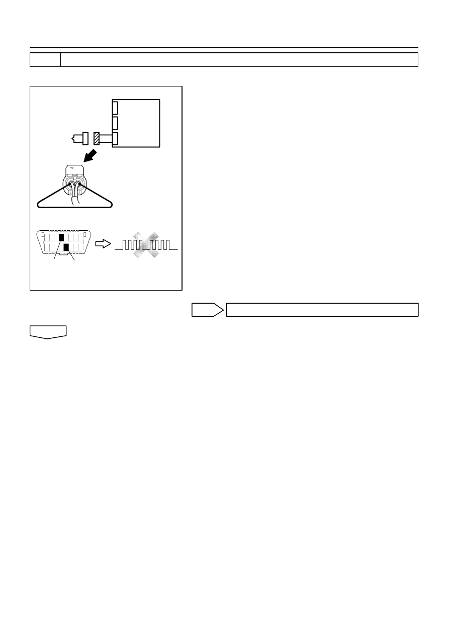
H01020
H16278
H10600 H01070
H40980
Side Squib (RH)
DTC B0111/44
DLC3
CG
Tc
Airbag
Sensor
Assy
Center
05–470
–
DIAGNOSTICS
SUPPLEMENTAL RESTRAINT SYSTEM (April, 2003)
635
Author:
Date:
2004 COROLLA (RM1037U)
2
CHECK AIR BAG SENSOR ASSY CENTER
SST
09843–18040
(a)
Connect the connector to the airbag sensor assy center.
(b)
Using a service wire, connect SFR+ and SFR– of the con-
nector (on the front seat airbag assy side) between the
airbag sensor assy center and the front seat airbag assy
(RH).
(c)
Connect the negative (–) terminal cable to the battery,
and wait at least for 2 seconds.
(d)
Turn the ignition switch to ON, and wait at least for 20 se-
conds.
(e)
Clear the DTC stored in memory (See page
05–424
).
(f)
Turn the ignition switch to LOCK, and wait at least for 20
seconds.
(g)
Turn the ignition switch to ON, and wait at least for 20 se-
conds.
(h)
Check the DTC (See page
05–424
).
OK:
DTC B0111/44 is not output.
HINT:
Codes other than code B0111/44 may be output at this time, but
they are not relevant to this check.
NG
REPLACE AIR BAG SENSOR ASSY CENTER
OK
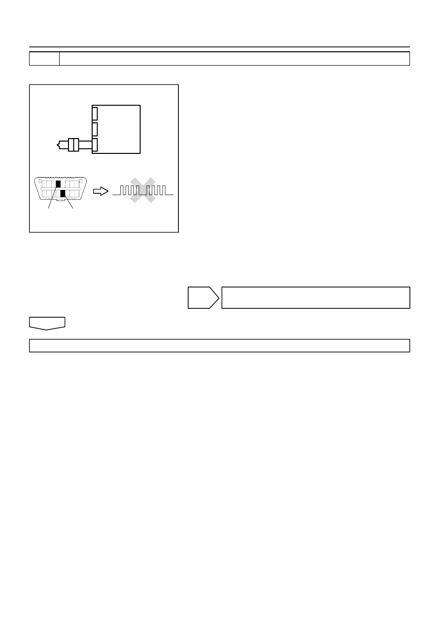
H01021
H10600 H01070
H40981
Side Squib (RH)
DTC B0111/44
DLC3
CG
Tc
Airbag
Sensor
Assy
Center
–
DIAGNOSTICS
SUPPLEMENTAL RESTRAINT SYSTEM (April, 2003)
05–471
636
Author:
Date:
2004 COROLLA (RM1037U)
3
CHECK SIDE SQUIB(RH)
SST
09843–18040
(a)
Turn the ignition switch to LOCK.
(b)
Disconnect the negative (–) terminal cable from the bat-
tery, and wait at least for 90 seconds.
(c)
Connect the front seat airbag assy (RH) connector.
(d)
Connect the negative (–) terminal cable to the battery,
and wait at least for 2 seconds.
(e)
Turn the ignition switch to ON, and wait at least for 20 se-
conds.
(f)
Clear the DTC stored in memory (See page
05–424
).
(g)
Turn the ignition switch to LOCK, and wait at least for 20
seconds.
(h)
Turn the ignition switch to ON, and wait at least for 20 se-
conds.
(i)
Check the DTC (See page
05–424
).
OK:
DTC B0111/44 is not output.
HINT:
Codes other than code B0111/44 may be output at this time, but
they are not relevant to this check.
NG
REPLACE SEPARATE TYPE FRONT SEAT
BACK ASSY
OK
USE SIMULATION METHOD TO CHECK

H01019
C82598
H41450
Airbag
Sensor
Assy
Center
Side Squib (RH)
05–472
–
DIAGNOSTICS
SUPPLEMENTAL RESTRAINT SYSTEM (April, 2003)
637
Author:
Date:
2004 COROLLA (RM1037U)
DTC
B0112/41 SHORT IN SIDE SQUIB (RH) CIRCUIT (TO
GROUND)
CIRCUIT DESCRIPTION
The side squib (RH) circuit consists of the airbag sensor assy center and front seat airbag assy (RH).
It causes the SRS to deploy when the SRS deployment conditions are satisfied.
DTC B0112/41 is recorded when ground short is detected in the side squib (RH) circuit.
DTC No.
DTC Detecting Condition
Trouble Area
B0112/41
Short circuit in side squib (RH) wire harness (to ground)
Side squib (RH) malfunction
Airbag sensor assy center malfunction
Front seat airbag assy (RH)
Airbag sensor assy center
Instrument panel wire No.3
WIRING DIAGRAM
See page
05–466
.
INSPECTION PROCEDURE
1
CHECK SIDE SQUIB(RH) CIRCUIT(AIRBAG SENSOR ASSY CENTER – FRONT
SEAT AIRBAG ASSY RH)
(a)
Disconnect the negative (–) terminal cable from the bat-
tery, and wait at least for 90 seconds.
(b)
Disconnect the connectors between the airbag sensor
assy center and the front seat airbag assy (RH).
(c)
For the connector (on the front seat airbag assy side) be-
tween the airbag sensor assy center and the front seat
airbag assy (RH), measure the resistance between SFR+
and body ground.
OK:
Resistance: 1 M
Ω
or Higher
NG
REPAIR OR REPLACE INSTRUMENT PANEL
WIRE NO.3(AIRBAG SENSOR ASSY CENTER –
FRONT SEAT AIRBAG ASSY RH)
OK
0525N–12
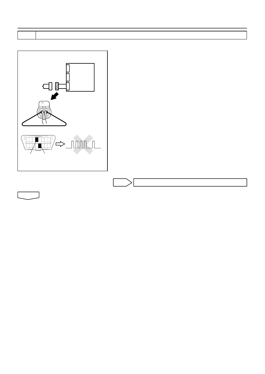
H01020
H16278
H10600 H01067
H42112
Side Squib (RH)
Airbag
Sensor
Assy
Center
DLC3
CG
Tc
DTC B0112/41
–
DIAGNOSTICS
SUPPLEMENTAL RESTRAINT SYSTEM (April, 2003)
05–473
638
Author:
Date:
2004 COROLLA (RM1037U)
2
CHECK AIR BAG SENSOR ASSY CENTER
SST
09843–18040
(a)
Connect the connector to the airbag sensor assy center.
(b)
Using a service wire, connect SFR+ and SFR– of the con-
nector (on the front seat airbag assy side) between the
airbag sensor assy center and the front seat airbag assy
(RH).
(c)
Connect the negative (–) terminal cable to the battery,
and wait at least for 2 seconds.
(d)
Turn the ignition switch to ON, and wait at least for 20 se-
conds.
(e)
Clear the DTC stored in memory (See page
05–424
).
(f)
Turn the ignition switch to LOCK, and wait at least for 20
seconds.
(g)
Turn the ignition switch to ON, and wait at least for 20 se-
conds.
(h)
Check the DTC (See page
05–424
).
OK:
DTC B0112/41 is not output.
HINT:
Codes other than code B0112/41 may be output at this time, but
they are not relevant to this check.
NG
REPLACE AIR BAG SENSOR ASSY CENTER
OK
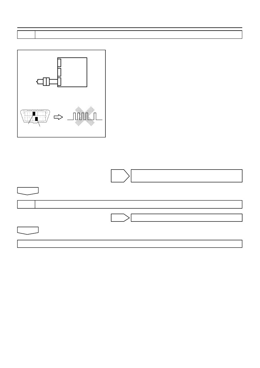
H01021
H10600 H01067
H40983
DTC B0112/41
Tc
CG
Side Squib (RH)
DLC3
Airbag
Sensor
Assy
Center
05–474
–
DIAGNOSTICS
SUPPLEMENTAL RESTRAINT SYSTEM (April, 2003)
639
Author:
Date:
2004 COROLLA (RM1037U)
3
CHECK SIDE SQUIB(RH)
SST
09843–18040
(a)
Turn the ignition switch to LOCK.
(b)
Disconnect the negative (–) terminal cable from the bat-
tery, and wait at least for 90 seconds.
(c)
Connect the front seat airbag assy (RH) connector.
(d)
Connect the negative (–) terminal cable to the battery,
and wait at least for 2 seconds.
(e)
Turn the ignition switch to ON, and wait at least for 20 se-
conds.
(f)
Clear the DTC stored in memory (See page
05–424
).
(g)
Turn the ignition switch to LOCK, and wait at least for 20
seconds.
(h)
Turn the ignition switch to ON, and wait at least for 20 se-
conds.
(i)
Check the DTC (See page
05–424
).
OK:
DTC B0112/41 is not output.
HINT:
Codes other than code B0112/41 may be output at this time, but
they are not relevant to this check.
NG
REPLACE SEPARATE TYPE FRONT SEAT
BACK ASSY
OK
4
USE SIMULATION METHOD TO CHECK
NG
Go to step 1
OK
REPLACE ALL SRS COMPONENTS INCLUDING THE WIRE HARNESS
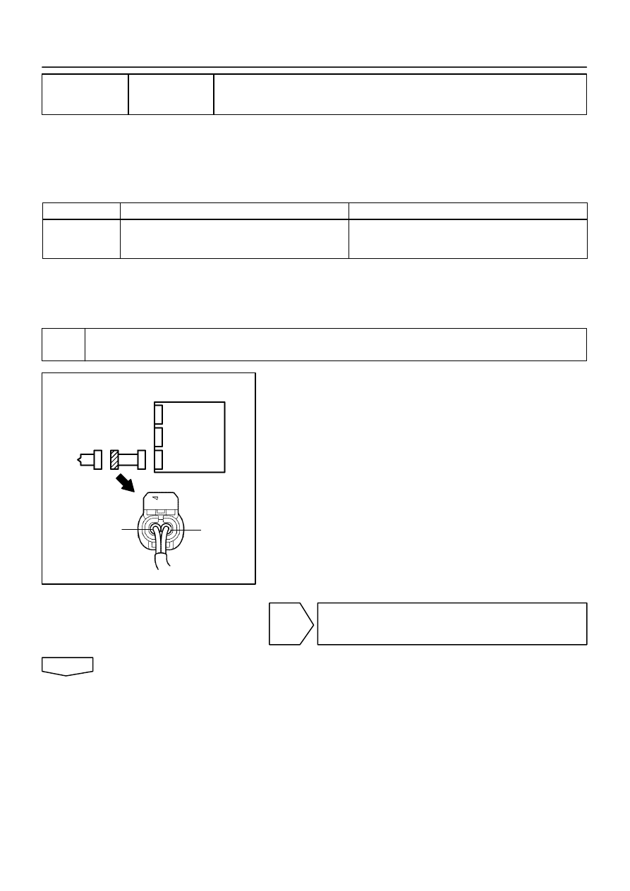
H01019
C82598
H40977
Side Squib (RH)
Airbag
Sensor
Assy
Center
SFR+
SFR–
–
DIAGNOSTICS
SUPPLEMENTAL RESTRAINT SYSTEM (April, 2003)
05–475
640
Author:
Date:
2004 COROLLA (RM1037U)
DTC
B0113/42 SHORT IN SIDE SQUIB (RH) CIRCUIT (TO
B+)
CIRCUIT DESCRIPTION
The side squib (RH) circuit consists of the airbag sensor assy center and front seat airbag assy (RH).
It causes the SRS to deploy when the SRS deployment conditions are satisfied.
DTC B0113/42 is recorded when a B+ short is detected in the side squib (RH) circuit.
DTC No.
DTC Detecting Condition
Trouble Area
B0113/42
Short circuit in side squib (RH) wire harness (to B+)
Side squib (RH) malfunction
Airbag sensor assy center malfunction
Front seat airbag assy (RH)
Airbag sensor assy center
Instrument panel wire No.3
WIRING DIAGRAM
See page
05–466
.
INSPECTION PROCEDURE
1
CHECK SIDE SQUIB(RH) CIRCUIT(AIRBAG SENSOR ASSY CENTER – FRONT
SEAT AIRBAG ASSY RH)
(a)
Disconnect the negative (–) terminal cable from the bat-
tery, and wait at least for 90 seconds.
(b)
Disconnect the connectors between the airbag sensor
assy center and the front seat airbag assy (RH).
(c)
Connect the negative (–) terminal cable to the battery,
and wait at least for 2 seconds.
(d)
Turn the ignition switch to ON.
(e)
For the connector (on the front seat airbag assy side) be-
tween the airbag sensor assy center and the front seat
airbag assy (RH), measure the voltage between SFR+
and body ground.
OK:
Voltage: Below 1 V
NG
REPAIR OR REPLACE INSTRUMENT PANEL
WIRE NO.3(AIRBAG SENSOR ASSY CENTER –
FRONT SEAT AIRBAG ASSY RH)
OK
0525O–13
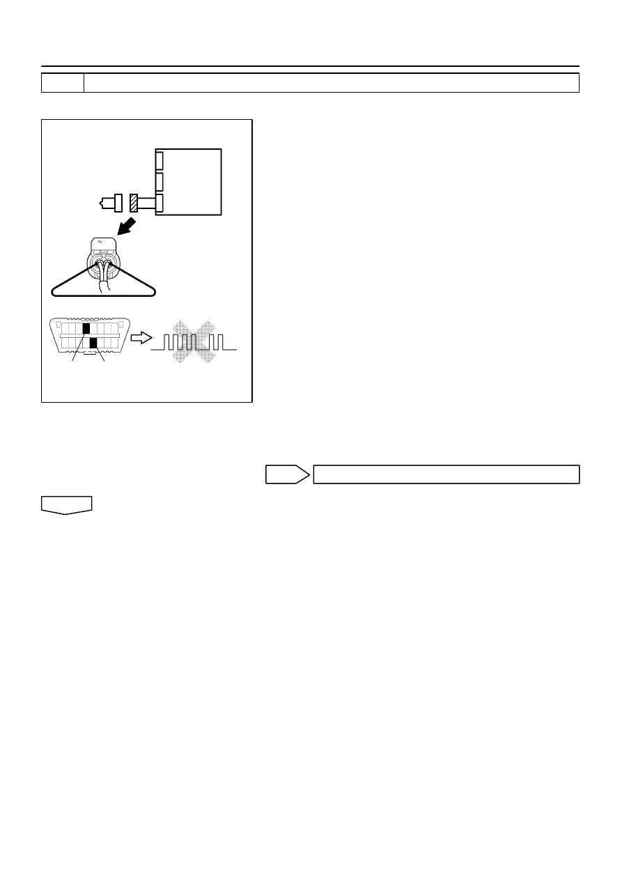
H01020
H16278
H10600 H01068
H42113
Side Squib (RH)
Airbag
Sensor
Assy
Center
DLC3
CG
Tc
DTC B0113/42
05–476
–
DIAGNOSTICS
SUPPLEMENTAL RESTRAINT SYSTEM (April, 2003)
641
Author:
Date:
2004 COROLLA (RM1037U)
2
CHECK AIR BAG SENSOR ASSY CENTER
SST
09843–18040
(a)
Turn the ignition switch to LOCK.
(b)
Disconnect the negative (–) terminal cable from the bat-
tery, and wait at least for 90 seconds.
(c)
Connect the connector to the airbag sensor assy center.
(d)
Using a service wire, connect SFR+ and SFR– of the con-
nector (on the front front seat airbag assy side) between
the airbag sensor assy center and the front seat airbag
assy (RH).
(e)
Connect the negative (–) terminal cable to the battery,
and wait at least for 2 seconds.
(f)
Turn the ignition switch to ON, and wait at least for 20 se-
conds.
(g)
Clear the DTC stored in memory (See page
05–424
).
(h)
Turn the ignition switch to LOCK, and wait at least for 20
seconds.
(i)
Turn the ignition switch to ON, and wait at least for 20 se-
conds.
(j)
Check the DTC (See page
05–424
).
OK:
DTC B0113/42 is not output.
HINT:
Codes other than code B0113/42 may be output at this time, but
they are not relevant to this check.
NG
REPLACE AIR BAG SENSOR ASSY CENTER
OK

H01021
H10600 H01068
H40985
Side Squib (RH)
CG
DTC B0113/42
DLC3
Tc
Airbag
Sensor
Assy
Center
–
DIAGNOSTICS
SUPPLEMENTAL RESTRAINT SYSTEM (April, 2003)
05–477
642
Author:
Date:
2004 COROLLA (RM1037U)
3
CHECK SIDE SQUIB(RH)
SST
09843–18040
(a)
Turn the ignition switch to LOCK.
(b)
Disconnect the negative (–) terminal cable from the bat-
tery, and wait at least for 90 seconds.
(c)
Connect the front seat airbag assy (RH) connector.
(d)
Connect the negative (–) terminal cable to the battery,
and wait at least for 2 seconds.
(e)
Turn the ignition switch to ON, and wait at least for 20 se-
conds.
(f)
Clear the DTC stored in memory (See page
05–424
).
(g)
Turn the ignition switch to LOCK, and wait at least for 20
seconds.
(h)
Turn the ignition switch to ON, and wait at least for 20 se-
conds.
(i)
Check the DTC (See page
05–424
).
OK:
DTC B0113/42 is not output.
HINT:
Codes other than code B0113/42 may be output at this time, but
they are not relevant to this check.
NG
REPLACE SEPARATE TYPE FRONT SEAT
BACK ASSY
OK
4
USE SIMULATION METHOD TO CHECK
NG
Go to step 1
OK
REPLACE ALL SRS COMPONENTS INCLUDING THE WIRE HARNESS
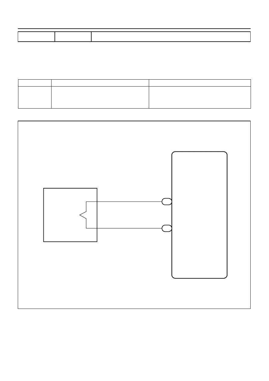
H01454
S6
Side Squib (LH)
Airbag Sensor Assy Center
SFL+
SFL–
Y–R
Y–G
1
2
5
6
A12
A12
05–478
–
DIAGNOSTICS
SUPPLEMENTAL RESTRAINT SYSTEM (April, 2003)
643
Author:
Date:
2004 COROLLA (RM1037U)
DTC
B0115/47 SHORT IN SIDE SQUIB (LH) CIRCUIT
CIRCUIT DESCRIPTION
The side squib (LH) circuit consists of the airbag sensor assy center and front seat airbag assy (LH).
It causes the SRS to deploy when the SRS deployment conditions are satisfied.
DTC B0115/47 is recorded when a short is detected in the side squib (LH) circuit.
DTC No.
DTC Detecting Condition
Trouble Area
B0115/47
Short circuit between SFL+ wire harness and SFL– wire
harness of squib
Side squib (LH) malfunction
Airbag sensor assy center malfunction
Front seat airbag assy (LH)
Airbag sensor assy center
Instrument panel wire No.3
WIRING DIAGRAM
055YI–04
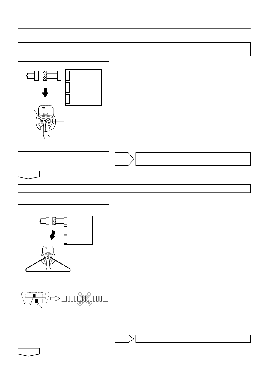
H01016
C82598
H40986
Side Squib (LH)
Airbag
Sensor
Assy
Center
SFL+
SFL–
H01017
H16278
H10600 H01073
H40987
Side Squib (LH)
DTC B0115/47
DLC3
Tc
CG
Airbag
Sensor
Assy
Center
–
DIAGNOSTICS
SUPPLEMENTAL RESTRAINT SYSTEM (April, 2003)
05–479
644
Author:
Date:
2004 COROLLA (RM1037U)
INSPECTION PROCEDURE
1
CHECK SIDE SQUIB(LH) CIRCUIT(AIRBAG SENSOR ASSY CENTER – FRONT
SEAT AIRBAG ASSY LH)
(a)
Disconnect the negative (–) terminal cable from the bat-
tery, and wait at least for 90 seconds.
(b)
Disconnect the connectors between the airbag sensor
assy center and the front seat airbag assy (LH).
(c)
Release the airbag activation prevention mechanism of
the connector (on the airbag sensor assy center side) be-
tween the airbag sensor assy center and the front seat
airbag assy (LH) (See page
05–424
).
(d)
For the connector (on the front seat airbag assy side) be-
tween the airbag sensor assy center and the front seat
airbag assy (LH), measure the resistance between SFL+
and SFL–.
OK:
Resistance: 1 M
Ω
or Higher
NG
REPAIR OR REPLACE INSTRUMENT PANEL
WIRE NO.3
OK
2
CHECK AIR BAG SENSOR ASSY CENTER
SST
09843–18040
(a)
Connect the connector to the airbag sensor assy center.
(b)
Using a service wire, connect SFL+ and SFL– of the con-
nector (on the front seat airbag assy side) between the
airbag sensor assy center and the front seat airbag assy
(LH).
(c)
Connect the negative (–) terminal cable to the battery,
and wait at least for 2 seconds.
(d)
Turn the ignition switch to ON, and wait at least for 20 se-
conds.
(e)
Clear the DTC stored in memory (See page
05–424
).
(f)
Turn the ignition switch to LOCK, and wait at least for 20
seconds.
(g)
Turn the ignition switch to ON, and wait at least for 20 se-
conds.
(h)
Check the DTC (See page
05–424
).
OK:
DTC B0115/47 is not output.
HINT:
Codes other than code B0115/47 may be output at this time, but
they are not relevant to this check.
NG
REPLACE AIR BAG SENSOR ASSY CENTER
OK
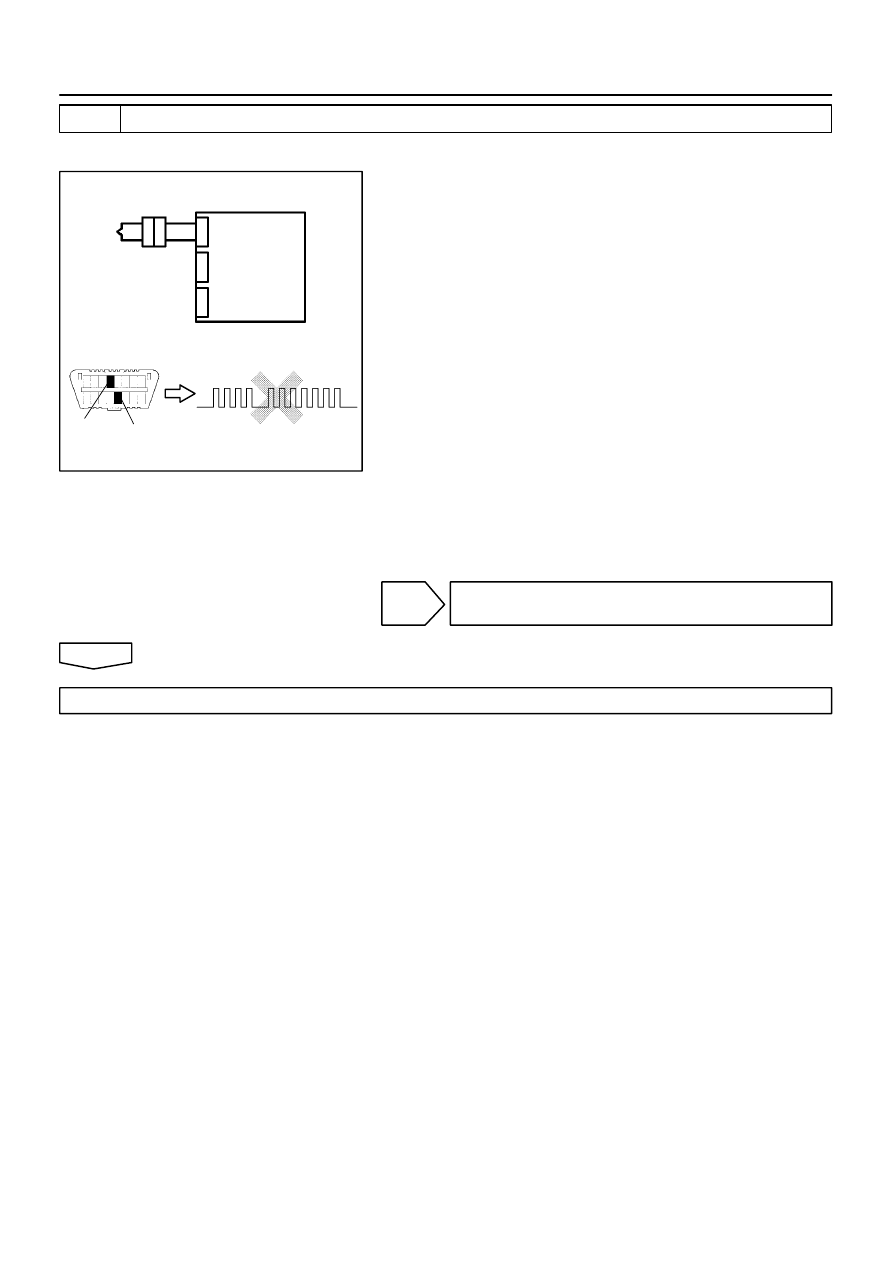
H01018
H10600 H01073
H40988
Side Squib (LH)
DTC B0115/47
DLC3
Tc
CG
Airbag
Sensor
Assy
Center
05–480
–
DIAGNOSTICS
SUPPLEMENTAL RESTRAINT SYSTEM (April, 2003)
645
Author:
Date:
2004 COROLLA (RM1037U)
3
CHECK SIDE SQUIB(LH)
SST
09843–18040
(a)
Turn the ignition switch to LOCK.
(b)
Disconnect the negative (–) terminal cable from the bat-
tery, and wait at least for 90 seconds.
(c)
Connect the front seat airbag assy (LH) connector.
(d)
Connect the negative (–) terminal cable to the battery,
and wait at least for 2 seconds.
(e)
Turn the ignition switch to ON, and wait at least for 20 se-
conds.
(f)
Clear the DTC stored in memory (See page
05–424
).
(g)
Turn the ignition switch to LOCK, and wait at least for 20
seconds.
(h)
Turn the ignition switch to ON, and wait at least for 20 se-
conds.
(i)
Check the DTC (See page
05–424
).
OK:
DTC B0115/47 is not output.
HINT:
Codes other than code B0115/47 may be output at this time, but
they are not relevant to this check.
NG
REPLACE SEPARATE TYPE FRONT SEAT
BACK ASSY
OK
USE SIMULATION METHOD TO CHECK
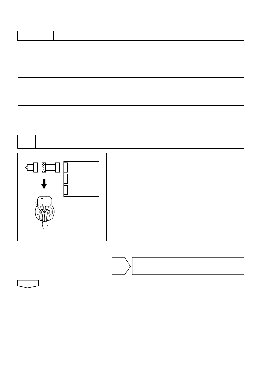
H01016
C82598
H40986
Side Squib (LH)
Airbag
Sensor
Assy
Center
SFL–
SFL+
–
DIAGNOSTICS
SUPPLEMENTAL RESTRAINT SYSTEM (April, 2003)
05–481
646
Author:
Date:
2004 COROLLA (RM1037U)
DTC
B0116/48 OPEN IN SIDE SQUIB (LH) CIRCUIT
CIRCUIT DESCRIPTION
The side squib (LH) circuit consists of the airbag sensor assy center and front seat airbag assy (LH).
It causes the SRS to deploy when the SRS deployment conditions are satisfied.
DTC B0116/48 is recorded when an open is detected in the side squib (LH) circuit.
DTC No.
DTC Detecting Condition
Trouble Area
B0116/48
Open circuit in SFL+ wire harness or SFL– wire harness
of squib
Side squib (LH) malfunction
Airbag sensor assy center malfunction
Front seat airbag assy (LH)
Airbag sensor assy center
Instrument panel wire No.3
WIRING DIAGRAM
See page
05–478
.
INSPECTION PROCEDURE
1
CHECK SIDE SQUIB(LH) CIRCUIT(AIRBAG SENSOR ASSY CENTER – FRONT
SEAT AIRBAG ASSY LH)
(a)
Disconnect the negative (–) terminal cable from the bat-
tery, and wait at least for 90 seconds.
(b)
Disconnect the connectors between the airbag sensor
assy center and the front seat airbag assy (LH).
(c)
For the connector (on the front seat airbag assy side) be-
tween the airbag sensor assy center and the front seat
airbag assy (LH), measure the resistance between SFL+
and SFL–.
OK:
Resistance: Below 1
Ω
NG
REPAIR OR REPLACE INSTRUMENT PANEL
WIRE NO.3(AIRBAG SENSOR ASSY CENTER –
FRONT SEAT AIRBAG ASSY LH)
OK
055YJ–04
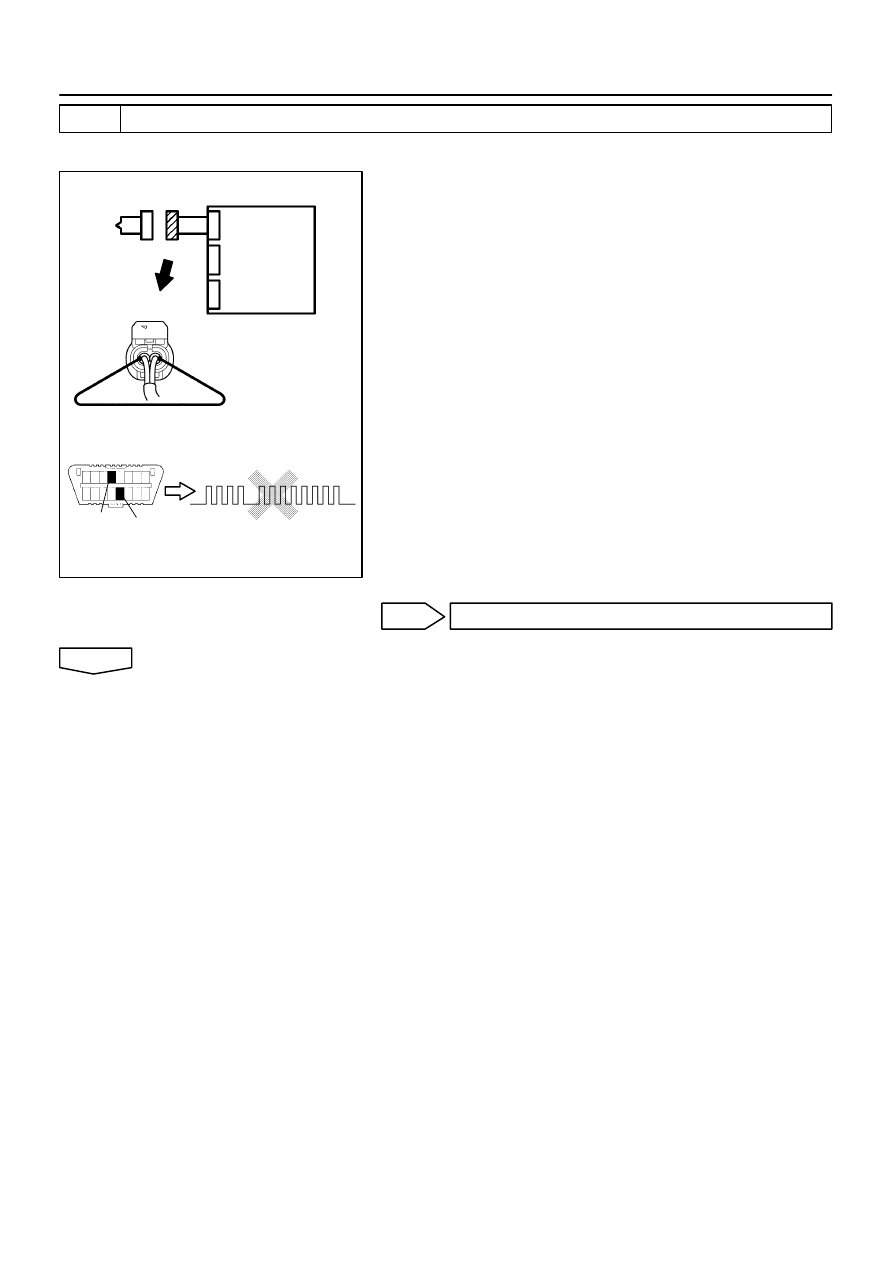
H01017
H16278
H10600 H01074
H40989
Side Squib (LH)
CG
DTC B0116/48
DLC3
Tc
Airbag
Sensor
Assy
Center
05–482
–
DIAGNOSTICS
SUPPLEMENTAL RESTRAINT SYSTEM (April, 2003)
647
Author:
Date:
2004 COROLLA (RM1037U)
2
CHECK AIR BAG SENSOR ASSY CENTER
SST
09843–18040
(a)
Connect the connector to the airbag sensor assy center.
(b)
Using a service wire, connect SFL+ and SFL– of the con-
nector (on the front seat airbag assy side) between the
airbag sensor assy center and the front seat airbag assy
(LH).
(c)
Connect the negative (–) terminal cable to the battery,
and wait at least 2 seconds.
(d)
Turn the ignition switch to ON, and wait at least for 20 se-
conds.
(e)
Clear the DTC stored in memory (See page
05–424
).
(f)
Turn the ignition switch to LOCK, and wait at least for 20
seconds.
(g)
Turn the ignition switch to ON, and wait at least for 20 se-
conds.
(h)
Check the DTC (See page
05–424
).
OK:
DTC B0116/48 is not output.
HINT:
Codes other than code B0116/48 may be output at this time, but
they are not relevant to this check.
NG
REPLACE AIR BAG SENSOR ASSY CENTER
OK
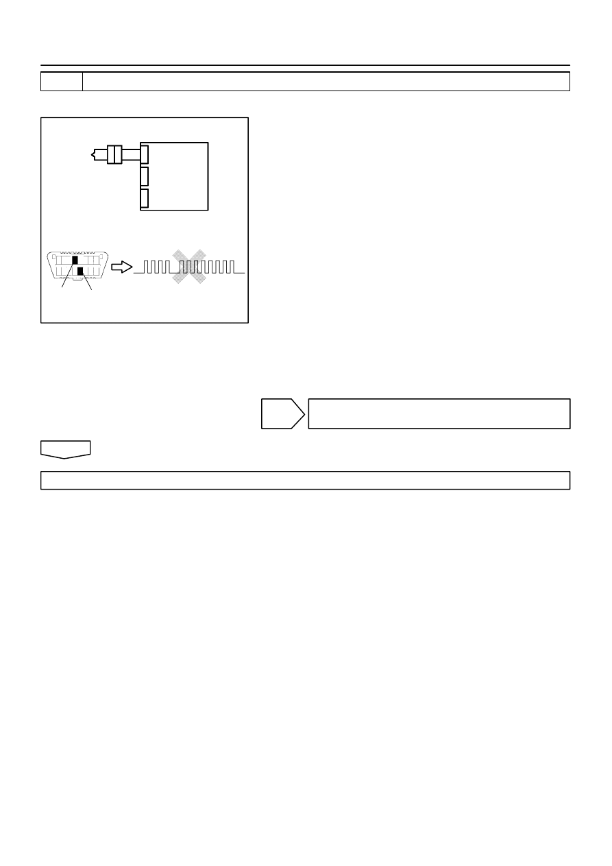
H01018
H10600 H01074
H40990
DLC3
DTC B0116/48
Tc
CG
Side Squib (LH)
Airbag
Sensor
Assy
Center
–
DIAGNOSTICS
SUPPLEMENTAL RESTRAINT SYSTEM (April, 2003)
05–483
648
Author:
Date:
2004 COROLLA (RM1037U)
3
CHECK SIDE SQUIB(LH)
SST
09843–18040
(a)
Turn the ignition switch to LOCK.
(b)
Disconnect the negative (–) terminal cable from the bat-
tery, and wait at least for 90 seconds.
(c)
Connect the front seat airbag assy (LH) connector.
(d)
Connect the negative (–) terminal cable to the battery,
and wait at least for 2 seconds.
(e)
Turn the ignition switch to ON, and wait at least for 20 se-
conds.
(f)
Clear the DTC stored in memory (See page
05–424
).
(g)
Turn the ignition switch to LOCK, and wait at least for 20
seconds.
(h)
Turn the ignition switch to ON, and wait at least for 20 se-
conds.
(i)
Check the DTC (See page
05–424
).
OK:
DTC B0116/48 is not output.
HINT:
Codes other than code B0116/48 may be output at this time, but
they are not relevant to this check.
NG
REPLACE SEPARATE TYPE FRONT SEAT
BACK ASSY
OK
USE SIMULATION METHOD TO CHECK
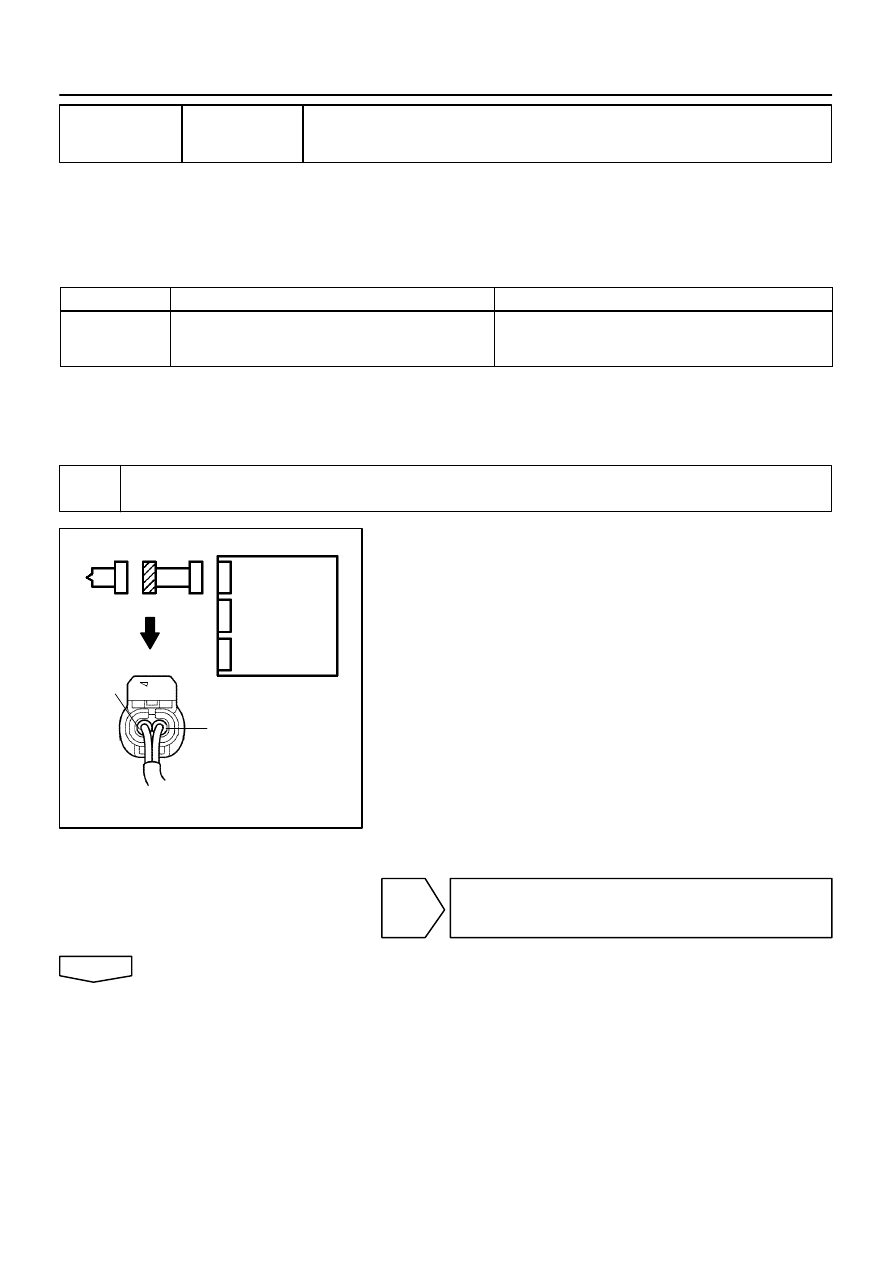
H01016
C82598
H40986
Airbag
Sensor
Assy
Center
SFL+
SFL–
Side Squib (LH)
05–484
–
DIAGNOSTICS
SUPPLEMENTAL RESTRAINT SYSTEM (April, 2003)
649
Author:
Date:
2004 COROLLA (RM1037U)
DTC
B0117/45 SHORT IN SIDE SQUIB (LH) CIRCUIT (TO
GROUND)
CIRCUIT DESCRIPTION
The side squib (LH) circuit consists of the airbag sensor assy center and front seat airbag assy (LH).
It causes the SRS to deploy when the SRS deployment conditions are satisfied.
DTC B0117/45 is recorded when a ground short is detected in the side squib (LH) circuit.
DTC No.
DTC Detecting Condition
Trouble Area
B0117/45
Short circuit in side squib (LH) wire harness (to ground)
Side squib (LH) malfunction
Airbag sensor assy center malfunction
Front seat airbag assy (LH)
Airbag sensor assy center
Instrument panel wire No.3
WIRING DIAGRAM
See page
05–478
.
INSPECTION PROCEDURE
1
CHECK SIDE SQUIB(LH) CIRCUIT(AIRBAG SENSOR ASSY CENTER – FRONT
SEAT AIRBAG ASSY LH)
(a)
Disconnect the negative (–) terminal cable from the bat-
tery, and wait at least for 90 seconds.
(b)
Disconnect the connectors between the airbag sensor
assy center and the front seat airbag assy (LH).
(c)
For the connector (on the front seat airbag assy side) be-
tween the airbag sensor assy center and the front seat
airbag assy (LH), measure the resistance between SFL+
and body ground.
OK:
Resistance: 1 M
Ω
or Higher
NG
REPAIR OR REPLACE INSTRUMENT PANEL
WIRE NO.3(AIRBAG SENSOR ASSY CENTER –
FRONT SEAT AIRBAG ASSY LH)
OK
0525R–13
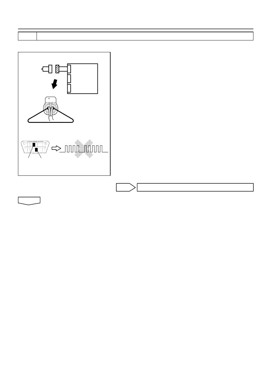
H01017
H16278
H10600 H01071
H40991
DLC3
CG
Tc
DTC B0117/45
Airbag
Sensor
Assy
Center
Side Squib (LH)
–
DIAGNOSTICS
SUPPLEMENTAL RESTRAINT SYSTEM (April, 2003)
05–485
650
Author:
Date:
2004 COROLLA (RM1037U)
2
CHECK AIR BAG SENSOR ASSY CENTER
SST
09843–18040
(a)
Connect the connector to the airbag sensor assy center.
(b)
Using a service wire, connect SFL+ and SFL– of the con-
nector (on the front seat airbag assy side) between the
airbag sensor assy center and the front seat airbag assy
(LH).
(c)
Connect the negative (–) terminal cable to the battery,
and wait at least for 2 seconds.
(d)
Turn the ignition switch to ON, and wait at least for 20 se-
conds.
(e)
Clear the DTC stored in memory (See page
05–424
).
(f)
Turn the ignition switch to LOCK, and wait at least for 20
seconds.
(g)
Turn the ignition switch to ON, and wait at least for 20 se-
conds.
(h)
Check the DTC (See page
05–424
).
OK:
DTC B0117/45 is not output.
HINT:
Codes other than code B0117/45 may be output at this time, but
they are not relevant to this check.
NG
REPLACE AIR BAG SENSOR ASSY CENTER
OK
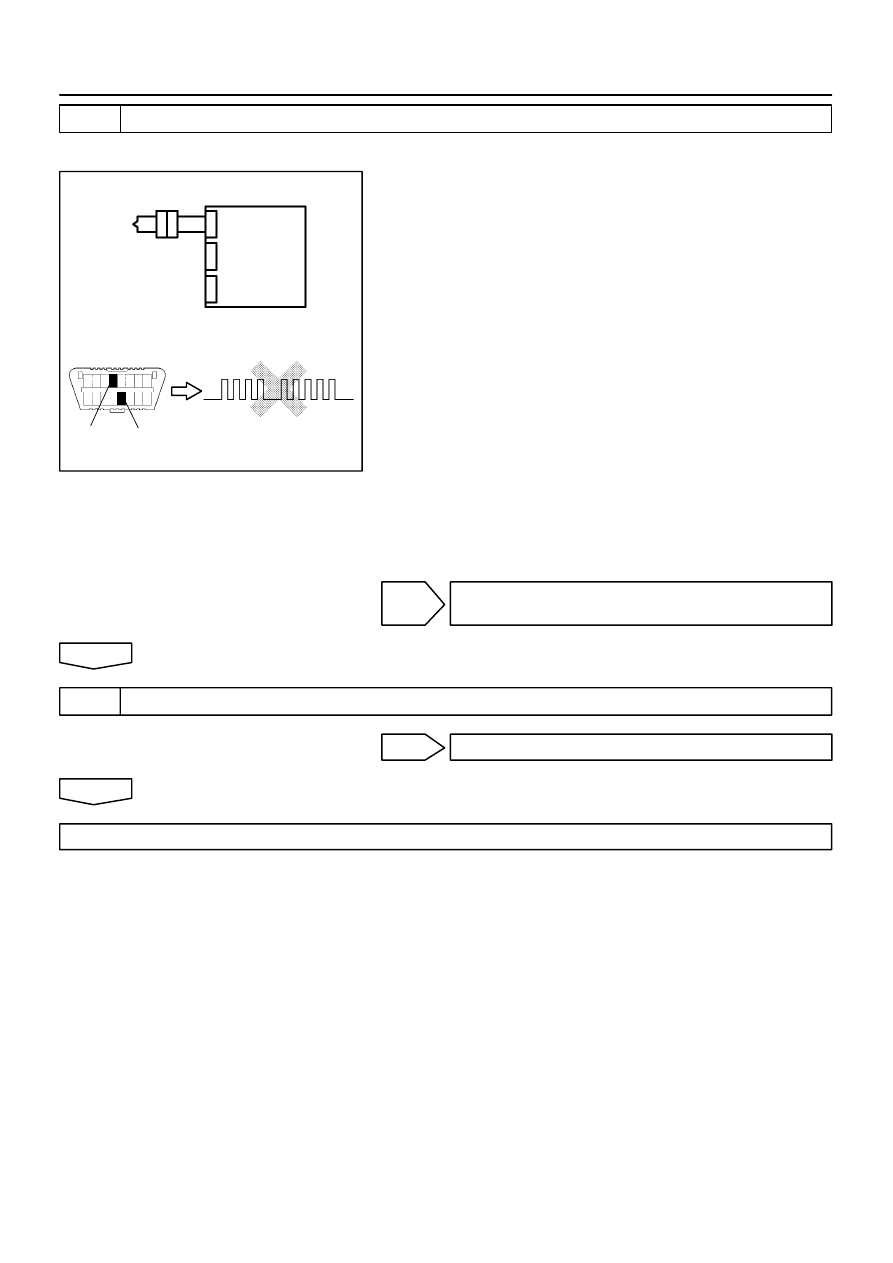
H01018
H10600 H01071
H40992
Tc
Side Squib (LH)
DTC B0117/45
DLC3
CG
Airbag
Sensor
Assy
Center
05–486
–
DIAGNOSTICS
SUPPLEMENTAL RESTRAINT SYSTEM (April, 2003)
651
Author:
Date:
2004 COROLLA (RM1037U)
3
CHECK SIDE SQUIB(LH)
SST
09843–18040
(a)
Turn the ignition switch to LOCK.
(b)
Disconnect the negative (–) terminal cable from the bat-
tery, and wait at least for 90 seconds.
(c)
Connect the front front seat airbag assy (LH) connector.
(d)
Connect the negative (–) terminal cable to the battery,
and wait at least for 2 seconds.
(e)
Turn the ignition switch to ON, and wait at least for 20 se-
conds.
(f)
Clear the DTC stored in memory (See page
05–424
).
(g)
Turn the ignition switch to LOCK, and wait at least for 20
seconds.
(h)
Turn the ignition switch to ON, and wait at least for 20 se-
conds.
(i)
Check the DTC (See page
05–424
).
OK:
DTC B0117/45 is not output.
HINT:
Codes other than code B0117/45 may be output at this time, but
they are not relevant to this check.
NG
REPLACE SEPARATE TYPE FRONT SEAT
BACK ASSY
OK
4
USE SIMULATION METHOD TO CHECK
NG
Go to step 1
OK
REPLACE ALL SRS COMPONENTS INCLUDING THE WIRE HARNESS
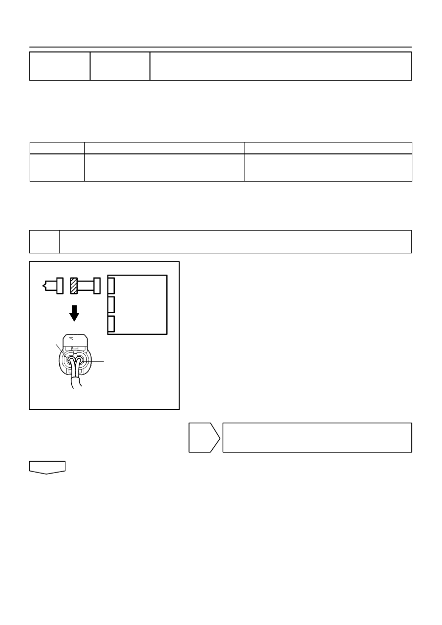
H01016
C82598
H40986
Side Squib (LH)
Airbag
Sensor
Assy
Center
SFL+
SFL–
–
DIAGNOSTICS
SUPPLEMENTAL RESTRAINT SYSTEM (April, 2003)
05–487
652
Author:
Date:
2004 COROLLA (RM1037U)
DTC
B0118/46 SHORT IN SIDE SQUIB (LH) CIRCUIT (TO
B+)
CIRCUIT DESCRIPTION
The side squib (LH) circuit consists of the airbag sensor assy center and front seat airbag assy (LH).
It causes the SRS to deploy when the SRS deployment conditions are satisfied.
DTC B0118/46 is recorded when a B+ short is detected in the side squib (LH) circuit.
DTC No.
DTC Detecting Condition
Trouble Area
B0118/46
Short circuit in side squib (LH) wire harness (to B+)
Side squib (LH) malfunction
Airbag sensor assy center malfunction
Front seat airbag assy (LH)
Airbag sensor assy center
Instrument panel wire No.3
WIRING DIAGRAM
See page
05–478
.
INSPECTION PROCEDURE
1
CHECK SIDE SQUIB(LH) CIRCUIT(AIRBAG SENSOR ASSY CENTER – FRONT
SEAT AIRBAG ASSY LH)
(a)
Disconnect the negative (–) terminal cable from the bat-
tery, and wait at least for 90 seconds.
(b)
Disconnect the connectors between the airbag sensor
assy center and the front seat airbag assy (LH).
(c)
Connect the negative (–) terminal cable to the battery,
and wait at least for 2 seconds.
(d)
Turn the ignition switch to ON.
(e)
For the connector (on the front seat airbag assy side) be-
tween the airbag sensor assy center and the front seat
airbag assy (LH), measure the voltage between SFL+
and body ground.
OK:
Voltage: Below 1 V
NG
REPAIR OR REPLACE INSTRUMENT PANEL
WIRE NO.3(AIRBAG SENSOR ASSY CENTER –
FRONT SEAT AIRBAG ASSY LH)
OK
0525S–12
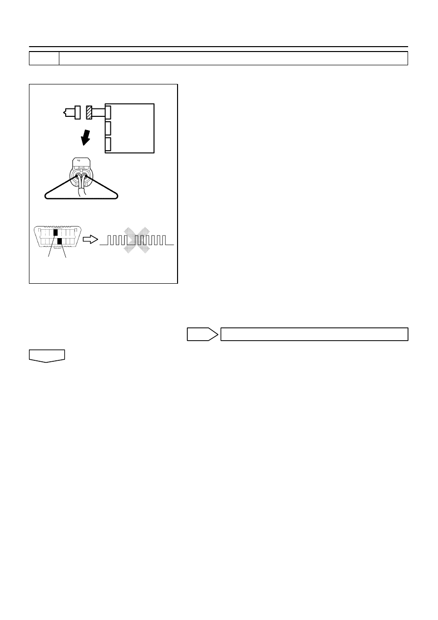
H01017
H16278
H10600 H01072
H40993
Side Squib (LH)
CG
Tc
DTC B0118/46
DLC3
Airbag
Sensor
Assy
Center
05–488
–
DIAGNOSTICS
SUPPLEMENTAL RESTRAINT SYSTEM (April, 2003)
653
Author:
Date:
2004 COROLLA (RM1037U)
2
CHECK AIR BAG SENSOR ASSY CENTER
SST
09843–18040
(a)
Turn the ignition switch to LOCK.
(b)
Disconnect the negative (–) terminal cable from the bat-
tery, and wait at least for 90 seconds.
(c)
Connect the connector to the airbag sensor assy center.
(d)
Using a service wire, connect SFL+ and SFL– of the con-
nector (on the front seat airbag assy side) between the
airbag sensor assy center and the front seat airbag assy
(LH).
(e)
Connect the negative (–) terminal cable to the battery,
and wait at least for 2 seconds.
(f)
Turn the ignition switch to ON, and wait at least for 20 se-
conds.
(g)
Clear the DTC stored in memory (See page
05–424
).
(h)
Turn the ignition switch to LOCK, and wait at least for 20
seconds.
(i)
Turn the ignition switch to ON, and wait at least for 20 se-
conds.
(j)
Check the DTC (See page
05–424
).
OK:
DTC B0118/46 is not output.
HINT:
Codes other than code B0118/46 may be output at this time, but
they are not relevant to this check.
NG
REPLACE AIR BAG SENSOR ASSY CENTER
OK
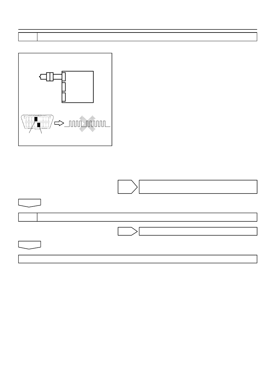
H01018
H10600 H01072
H40994
Side Squib (LH)
DTC B0118/46
DLC3
Tc
CG
Airbag
Sensor
Assy
Center
–
DIAGNOSTICS
SUPPLEMENTAL RESTRAINT SYSTEM (April, 2003)
05–489
654
Author:
Date:
2004 COROLLA (RM1037U)
3
CHECK SIDE SQUIB(LH)
SST
09843–18040
(a)
Turn the ignition switch to LOCK.
(b)
Disconnect the negative (–) terminal cable from the bat-
tery, and wait at least for 90 seconds.
(c)
Connect the front seat airbag assy (LH) connector.
(d)
Connect the negative (–) terminal cable to the battery,
and wait at least for 2 seconds.
(e)
Turn the ignition switch to ON, and wait at least for 20 se-
conds.
(f)
Clear the DTC stored in memory (See page
05–424
).
(g)
Turn the ignition switch to LOCK, and wait at least for 20
seconds.
(h)
Turn the ignition switch to ON, and wait at least for 20 se-
conds.
(i)
Check the DTC (See page
05–424
).
OK:
DTC B0118/46 is not output.
HINT:
Codes other than code B0118/46 may be output at this time, but
they are not relevant to this check.
NG
REPLACE SEPARATE TYPE FRONT SEAT
BACK ASSY
OK
4
USE SIMULATION METHOD TO CHECK
NG
Go to step 1
OK
REPLACE ALL SRS COMPONENTS INCLUDING THE WIRE HARNESS
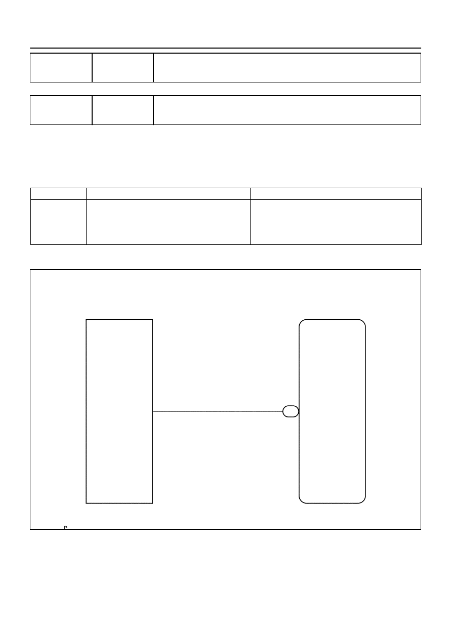
H16798
B6
Seat Belt Buckle Switch (LH)
Airbag Sensor Assy Center
11
LBE+
A12
G
2
05–490
–
DIAGNOSTICS
SUPPLEMENTAL RESTRAINT SYSTEM (April, 2003)
655
Author:
Date:
2004 COROLLA (RM1037U)
DTC
B0126/27 SEAT BELT BUCKLE SWITCH (LH)
MALFUNCTION
DTC
B0127/27 SEAT BELT BUCKLE SWITCH (LH)
MALFUNCTION
CIRCUIT DESCRIPTION
The seat belt buckle switch (LH) circuit consists of the airbag sensor assy center and front seat inner belt
assy (LH).
DTC B0126/B0127/27 is recorded when a malfunction is detected in the seat belt buckle switch (LH) circuit.
DTC No.
DTC Detecting Condition
Trouble Area
B0126/B0127/27
Short circuit in LBE+ wire harness (to ground)
Short circuit in LBE+ wire harness (to B+)
Open circuit in LBE+ wire harness
Front seat inner belt assy (LH) malfunction
Airbag sensor assy center malfunction
Front seat inner belt assy (LH)
Airbag sensor assy center
Instrument panel wire No.3
WIRING DIAGRAM
055YR–05
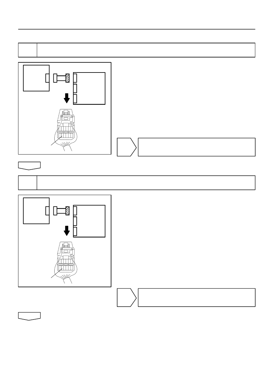
H01010
C81676
H40447
Airbag
Sensor
Assy
Center
Front Seat
Inner
Belt
Assy LH
LBE+
H01010
C81676
H40447
Airbag
Sensor
Assy
Center
Front Seat
Inner
Belt
Assy LH
LBE+
–
DIAGNOSTICS
SUPPLEMENTAL RESTRAINT SYSTEM (April, 2003)
05–491
656
Author:
Date:
2004 COROLLA (RM1037U)
INSPECTION PROCEDURE
1
CHECK WIRE HARNESS(AIRBAG SENSOR ASSY CENTER – FRONT SEAT INNER
BELT ASSY LH)
(a)
Disconnect the negative (–) terminal cable from the bat-
tery, and wait at least for 90 seconds.
(b)
Disconnect the connectors between the airbag sensor
assy center and the front seat inner belt assy (LH).
(c)
For the connector (on the airbag sensor assy center side)
between the airbag sensor assy center and the front seat
inner belt assy (LH), measure the resistance between
LBE+ and body ground.
OK:
Resistance: 1 M
Ω
or Higher
NG
REPAIR OR REPLACE INSTRUMENT PANEL
WIRE NO.3 (AIRBAG SENSOR ASSY CENTER –
FRONT SEAT INNER BELT ASSY LH)
OK
2
CHECK WIRE HARNESS(AIRBAG SENSOR ASSY CENTER – FRONT SEAT INNER
BELT ASSY LH)
(a)
Connect the negative (–) terminal cable to the battery,
and wait at least for 2 seconds.
(b)
Turn the ignition switch to ON.
(c)
For the connector (on the airbag sensor assy center side)
between the airbag sensor assy center and the front seat
inner belt assy (LH), measure the voltage between LBE+
and body ground.
OK:
Voltage: Below 1 V
NG
REPAIR OR REPLACE INSTRUMENT PANEL
WIRE NO.3 (AIRBAG SENSOR ASSY CENTER –
FRONT SEAT INNER BELT ASSY LH)
OK
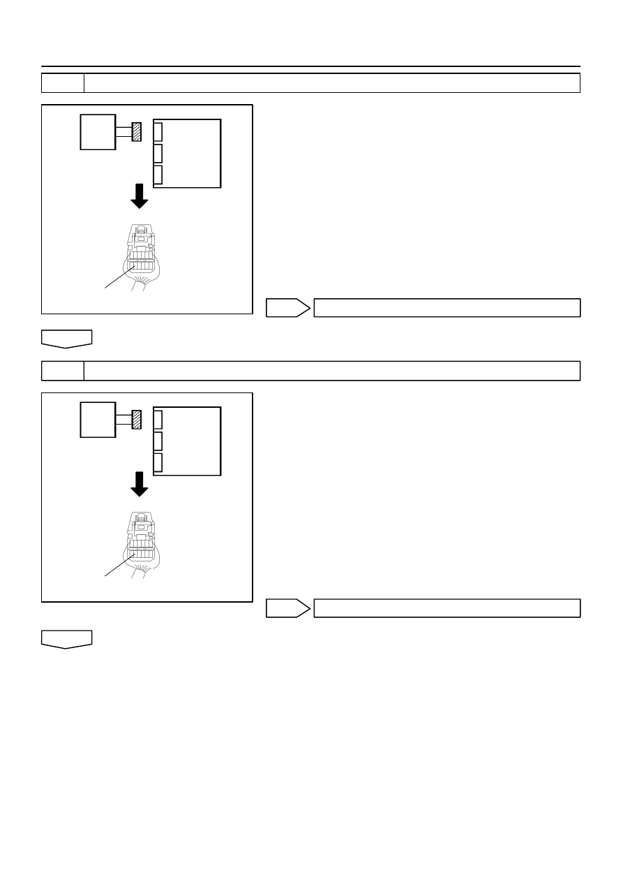
H41987
Airbag
Sensor
Assy
Center
Front Seat Inner
Belt Assy LH
LBE+
H41987
Airbag
Sensor
Assy
Center
Front Seat Inner
Belt Assy LH
LBE+
05–492
–
DIAGNOSTICS
SUPPLEMENTAL RESTRAINT SYSTEM (April, 2003)
657
Author:
Date:
2004 COROLLA (RM1037U)
3
CHECK FRONT SEAT INNER BELT ASSY LH
(a)
Turn the ignition switch to LOCK.
(b)
Disconnect the negative (–) terminal cable from the bat-
tery, and wait at least for 90 seconds.
(c)
Connect the connector of the front seat inner belt assy
(LH).
(d)
Unlock the seat belt for the front driver’s seat.
(e)
For the connector (on the airbag sensor assy center side),
measure the resistance between LBE+ and body ground.
OK:
Resistance: 1.0 k
Ω
– 1.6 k
Ω
NG
REPLACE FRONT SEAT INNER BELT ASSY LH
OK
4
CHECK FRONT SEAT INNER BELT ASSY LH
(a)
Lock the seat belt for the front driver’s seat.
(b)
For the connector (on the airbag sensor assy center side),
measure the resistance between LBE+ and body ground.
OK:
Resistance: 100
Ω
– 500
Ω
NG
REPLACE FRONT SEAT INNER BELT ASSY LH
OK
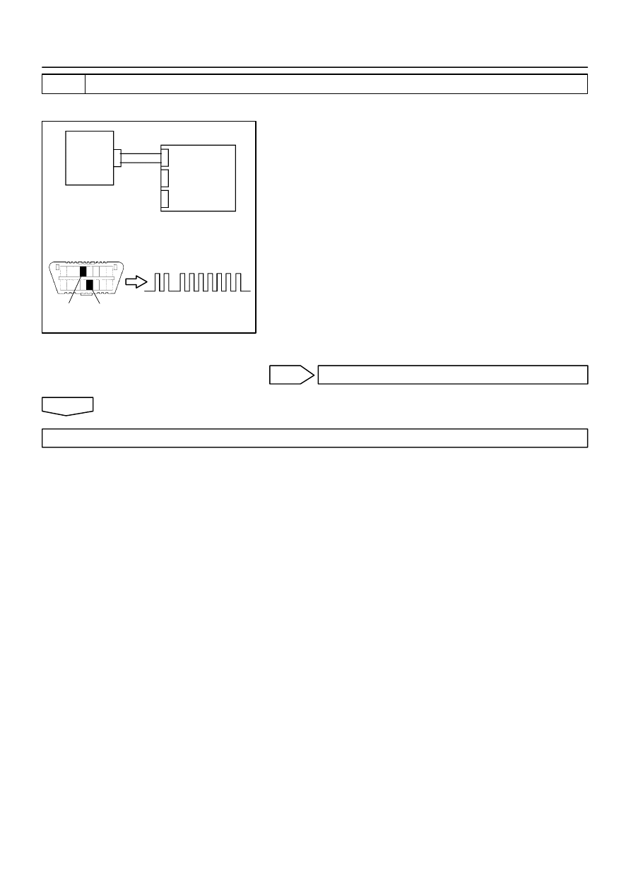
C85269
H10600 C85273
H41027
Front Seat Inner
Belt Assy LH
Airbag
Sensor
Assy Center
DTC B0126/B0127/27
DLC3
TC
CG
–
DIAGNOSTICS
SUPPLEMENTAL RESTRAINT SYSTEM (April, 2003)
05–493
658
Author:
Date:
2004 COROLLA (RM1037U)
5
CHECK AIR BAG SENSOR ASSY CENTER
SST
09843–18040
(a)
Connect the connector to the airbag sensor assy center.
(b)
Connect the negative (–) terminal cable to the battery,
and wait at least for 2 seconds.
(c)
Turn the ignition switch to ON, and wait at least for 20 se-
conds.
(d)
Clear the DTC stored in memory (See page
05–424
).
(e)
Turn the ignition switch to LOCK, and wait at least for 20
seconds.
(f)
Turn the ignition switch to ON, and wait at least for 20 se-
conds.
(g)
Check the DTC (See page
05–424
).
OK:
DTC B0126/B0127/27 is not output.
HINT:
Codes other than code B0126/B0127/27 may be output at this
time, but they are not relevant to this check.
NG
REPLACE AIR BAG SENSOR ASSY CENTER
OK
USE SIMULATION METHOD TO CHECK

H01454
A14
5
PR+
6
PR–
Y–B
Y
1
2
Airbag Sensor Assy Center
P13
P/T Squib (RH)
A14
05–494
–
DIAGNOSTICS
SUPPLEMENTAL RESTRAINT SYSTEM (April, 2003)
659
Author:
Date:
2004 COROLLA (RM1037U)
DTC
B0130/63 SHORT IN P/T SQUIB (RH) CIRCUIT
CIRCUIT DESCRIPTION
The P/T squib (RH) circuit consists of the airbag sensor assy center and seat belt pretensioner (RH).
It causes the SRS to deploy when the SRS deployment conditions are satisfied.
DTC B0130/63 is recorded when a short is detected in the P/T squib (RH) circuit.
DTC No.
DTC Detecting Condition
Trouble Area
B0130/63
Short circuit between PR+ wire harness and PR– wire
harness of squib
P/T squib (RH) malfunction
Airbag sensor assy center malfunction
Seat belt pretensioner (RH)
Airbag sensor assy center
Instrument panel wire No.3
WIRING DIAGRAM
055YV–05
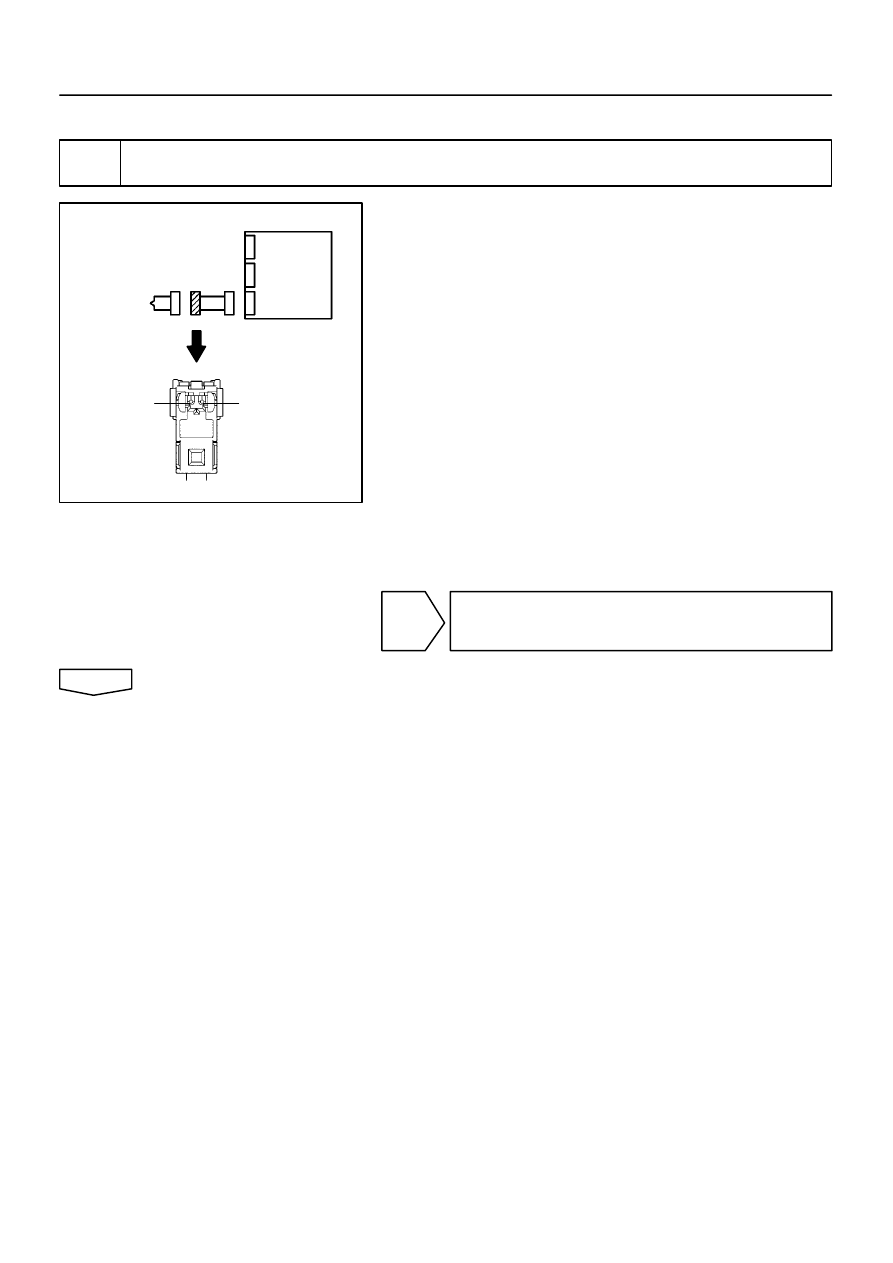
H01019
C81077
H40048
Airbag
Sensor
Assy
Center
P/T Squib (RH)
PR+
PR–
–
DIAGNOSTICS
SUPPLEMENTAL RESTRAINT SYSTEM (April, 2003)
05–495
660
Author:
Date:
2004 COROLLA (RM1037U)
INSPECTION PROCEDURE
1
CHECK P/T SQUIB(RH) CIRCUIT(AIRBAGA SENSOR ASSY CENTER – FRONT
SEAT OUTER BELT ASSY RH)
(a)
Disconnect the negative (–) terminal cable from the bat-
tery, and wait at least for 90 seconds.
(b)
Disconnect the connectors between the airbag sensor
assy center and the seat belt pretensioner (RH).
HINT:
Make sure that the connector is not damaged (The lock button
is not disengaged, or the claw of the lock is not deformed or
damaged). If the damage is found, replace the wire harness.
(c)
Release the airbag activation prevention mechanism of
the connector (on the airbag sensor assy center side) be-
tween the airbag sensor assy center and the seat belt pre-
tensioner (RH) (See page
05–424
).
(d)
For the connector (on the seat belt pretensioner side) be-
tween the airbag sensor assy center and the seat belt pre-
tensioner (RH), measure the resistance between PR+
and PR–.
OK:
Resistance: 1 M
Ω
or Higher
NG
REPAIR OR REPLACE INSTRUMENT PANEL
WIRE NO.3(AIRBAG SENSOR ASSY CENTER –
FRONT SEAT OUTER BELT ASSY RH)
OK
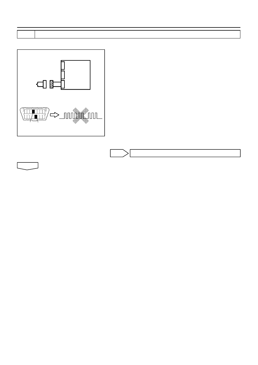
H10600
H01020
H01082
H10600
H01020
H01082
H40049
DLC3
CG
Tc
DTC B0130/63
P/T Squib (RH)
Airbag
Sensor
Assy
Center
05–496
–
DIAGNOSTICS
SUPPLEMENTAL RESTRAINT SYSTEM (April, 2003)
661
Author:
Date:
2004 COROLLA (RM1037U)
2
CHECK AIR BAG SENSOR ASSY CENTER
SST
09843–18040
(a)
Connect the connector to the airbag sensor assy center.
(b)
Connect the negative (–) terminal cable to the battery,
and wait at least for 2 seconds.
(c)
Turn the ignition switch to ON, and wait at least for 20 se-
conds.
(d)
Clear the DTC stored in memory (See page
05–424
).
(e)
Turn the ignition switch to LOCK, and wait at least for 20
seconds.
(f)
Turn the ignition switch to ON, and wait at least for 20 se-
conds.
(g)
Check the DTC (See page
05–424
).
OK:
DTC B0130/63 is not output.
HINT:
Codes other than code B0130/63 may be output at this time, but
they are not relevant to this check.
NG
REPLACE AIR BAG SENSOR ASSY CENTER
OK
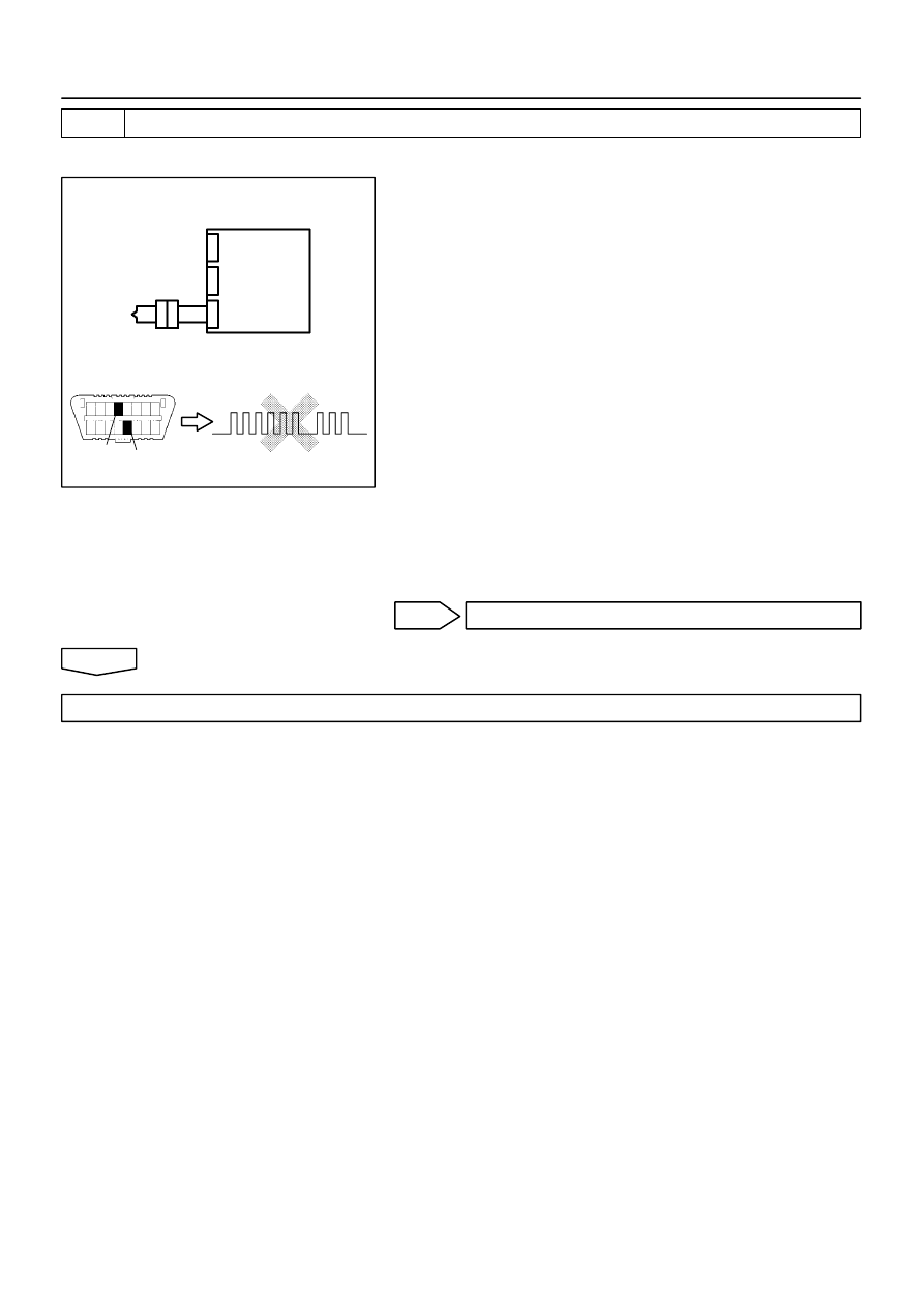
H10600 H01082
H01021
H40050
DLC3
CG
Tc
DTC B0130/63
P/T Squib (RH)
Airbag
Sensor
Assy
Center
–
DIAGNOSTICS
SUPPLEMENTAL RESTRAINT SYSTEM (April, 2003)
05–497
662
Author:
Date:
2004 COROLLA (RM1037U)
3
CHECK P/T SQUIB (RH)
SST
09843–18040
(a)
Turn the ignition switch to LOCK.
(b)
Disconnect the negative (–) terminal cable from the bat-
tery, and wait at least for 90 seconds.
(c)
Connect the seat belt pretensioner (RH) connector.
(d)
Connect the negative (–) terminal cable to the battery,
and wait at least for 2 seconds.
(e)
Turn the ignition switch to ON, and wait at least for 20 se-
conds.
(f)
Clear the DTC stored in memory (See page
05–424
).
(g)
Turn the ignition switch to LOCK, and wait at least for 20
seconds.
(h)
Turn the ignition switch to ON, and wait at least for 20 se-
conds.
(i)
Check the DTC (See page
05–424
).
OK:
DTC B0130/63 is not output.
HINT:
Codes other than code B0130/63 may be output at this time, but
they are not relevant to this check.
NG
REPLACE FRONT SEAT OUTER BELT ASSY RH
OK
USE SIMULATION METHOD TO CHECK
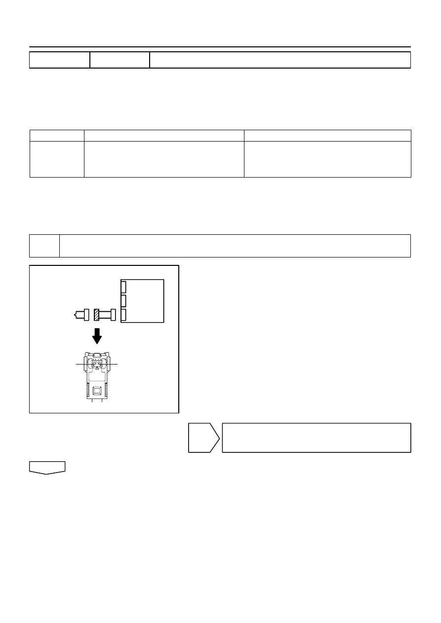
H01019
C81077
H40048
P/T Squib (RH)
Airbag
Sensor
Assy
Center
PR+
PR–
05–498
–
DIAGNOSTICS
SUPPLEMENTAL RESTRAINT SYSTEM (April, 2003)
663
Author:
Date:
2004 COROLLA (RM1037U)
DTC
B0131/64 OPEN IN P/T (RH) CIRCUIT
CIRCUIT DESCRIPTION
The P/T squib circuit (RH) consists of the airbag sensor assy center and seat belt pretensioner (RH).
It causes the SRS to deploy when the SRS deployment conditions are satisfied.
DTC B0131/64 is recorded when an open is detected in the P/T squib (RH) circuit.
DTC No.
DTC Detecting Condition
Trouble Area
B0131/64
Open circuit in PR+ wire harness or PR– wire harness of
squib
P/T squib (RH) malfunction
Airbag sensor assy center malfunction
Seat belt pretensioner (RH)
Airbag sensor assy center
Instrument panel wire No.3
WIRING DIAGRAM
See page
05–494
.
INSPECTION PROCEDURE
1
CHECK P/T SQUIB(RH) CIRCUIT(AIRBAG SENSOR ASSY CENTER – FRONT
SEAT OUTER BELT ASSY RH)
(a)
Disconnect the negative (–) terminal cable from the bat-
tery, and wait at least for 90 seconds.
(b)
Disconnect the connectors between the airbag sensor
assy center and the seat belt pretensioner (RH).
(c)
For the connector (on the seat belt pretensioner side) be-
tween the airbag sensor assy center and the seat belt pre-
tensioner (RH), measure the resistance between PR+
and PR–.
OK:
Resistance: Below 1
Ω
NG
REPAIR OR REPLACE INSTRUMENT PANEL
WIRE NO.3(AIRBAG SENSOR ASSY CENTER –
FRONT SEAT OUTER BELT ASSY RH)
OK
055YY–05
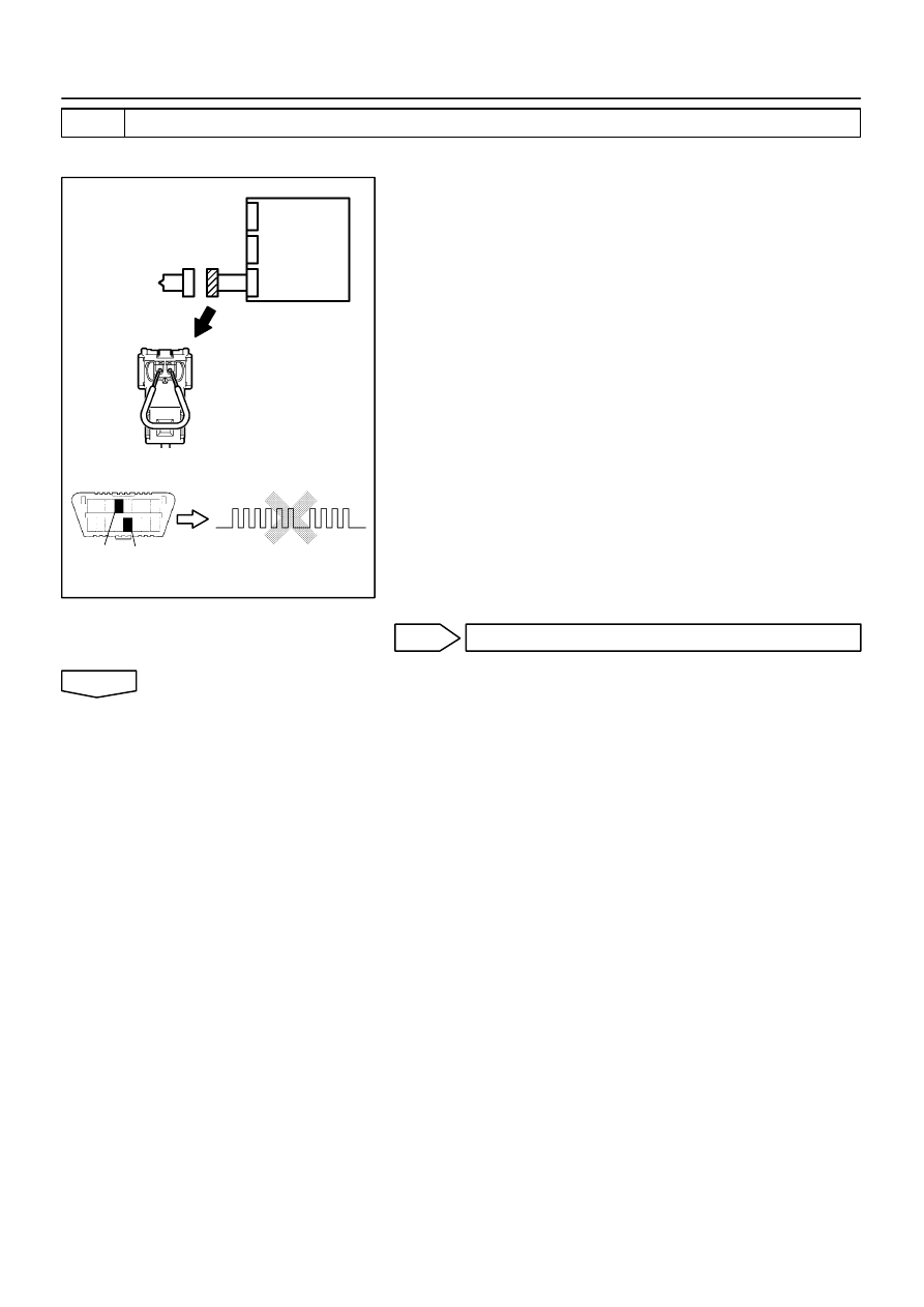
H01020
C85243
H10600 H01083
H40951
P/T Squib (RH)
DLC3
CG
Tc
DTC B0131/64
Airbag
Sensor
Assy
Center
–
DIAGNOSTICS
SUPPLEMENTAL RESTRAINT SYSTEM (April, 2003)
05–499
664
Author:
Date:
2004 COROLLA (RM1037U)
2
CHECK AIR BAG SENSOR ASSY CENTER
SST
09843–18040
(a)
Connect the connector to the airbag sensor assy center.
(b)
Using a service wire, connect PR+ and PR– of the con-
nector (on the seat belt pretensioner side) between the
airbag sensor assy center and the seat belt pretensioner
(RH).
(c)
Connect the negative (–) terminal cable to the battery,
and wait at least for 2 seconds.
(d)
Turn the ignition switch to ON, and wait at least for 20 se-
conds.
(e)
Clear the DTC stored in memory (See page
05–424
).
(f)
Turn the ignition switch to LOCK, and wait at least for 20
seconds.
(g)
Turn the ignition switch to ON, and wait at least for 20 se-
conds.
(h)
Check the DTC (See page
05–424
).
OK:
DTC B0131/64 is not output.
HINT:
Codes other than code B0131/64 may be output at this time, but
they are not relevant to this check.
NG
REPLACE AIR BAG SENSOR ASSY CENTER
OK
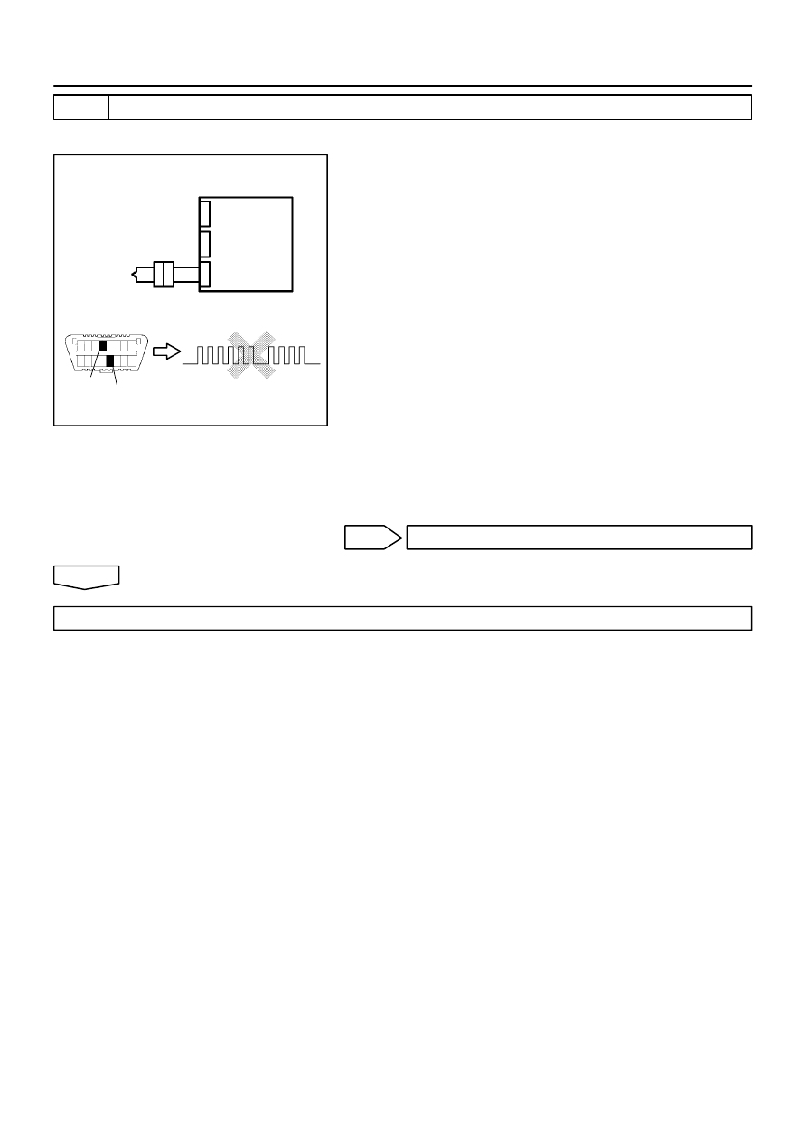
H10600
H01021
H01083
H40051
P/T Squib (RH)
DLC3
CG
Tc
DTC B0131/64
Airbag
Sensor
Assy
Center
05–500
–
DIAGNOSTICS
SUPPLEMENTAL RESTRAINT SYSTEM (April, 2003)
665
Author:
Date:
2004 COROLLA (RM1037U)
3
CHECK P/T SQUIB (RH)
SST
09843–18040
(a)
Turn the ignition switch to LOCK.
(b)
Disconnect the negative (–) terminal cable from the bat-
tery, and wait at least for 90 seconds.
(c)
Connect the seat belt pretensioner (RH) connector.
(d)
Connect the negative (–) terminal cable to the battery,
and wait at least for 2 seconds.
(e)
Turn the ignition switch to ON, and wait at least for 20 se-
conds.
(f)
Clear the DTC stored in memory (See page
05–424
).
(g)
Turn the ignition switch to LOCK, and wait at least for 20
seconds.
(h)
Turn the ignition switch to ON, and wait at least for 20 se-
conds.
(i)
Check the DTC (See page
05–424
).
OK:
DTC B0131/64 is not output.
HINT:
Codes other than code B0131/64 may be output at this time, but
they are not relevant to this check.
NG
REPLACE FRONT SEAT OUTER BELT ASSY RH
OK
USE SIMULATION METHOD TO CHECK
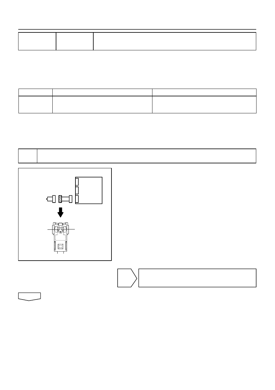
H01019
C81077
H40048
P/T Squib (RH)
PR+
PR–
Airbag
Sensor
Assy
Center
–
DIAGNOSTICS
SUPPLEMENTAL RESTRAINT SYSTEM (April, 2003)
05–501
666
Author:
Date:
2004 COROLLA (RM1037U)
DTC
B0132/61 SHORT IN P/T SQUIB (RH) CIRCUIT (TO
GROUND)
CIRCUIT DESCRIPTION
The P/T squib (RH) circuit consists of the airbag sensor assy center and seat belt pretensioner (RH).
It causes the SRS to deploy when the SRS deployment conditions are satisfied.
DTC B0132/61 is recorded when a ground short is detected in the P/T squib (RH) circuit.
DTC No.
DTC Detecting Condition
Trouble Area
B0132/61
Short circuit in P/T squib (RH) wire harness (to ground)
P/T squib (RH) malfunction
Airbag sensor assy center malfunction
Seat belt pretensioner (RH)
Airbag sensor assy center
Instrument panel wire No.3
WIRING DIAGRAM
See page
05–494
.
INSPECTION PROCEDURE
1
CHECK P/T SQUIB(RH) CIRCUIT(AIRBAG SENSOR ASSY CENTER – FRONT
SEAT OUTER BELT ASSY RH)
(a)
Disconnect the negative (–) terminal cable from the bat-
tery, and wait at least for 90 seconds.
(b)
Disconnect the connectors between the airbag sensor
assy center and the seat belt pretensioner (RH).
(c)
For the connector (on the seat belt pretensioner side) be-
tween the airbag sensor assy center and the seat belt pre-
tensioner (RH), measure the resistance between PR+
and body ground.
OK:
Resistance: 1 M
Ω
or Higher
NG
REPAIR OR REPLACE INSTRUMENT PANEL
WIRE NO.3(AIRBAG SENSOR ASSY CENTER –
FRONT SEAT OUTER BELT ASSY RH)
OK
0525V–14
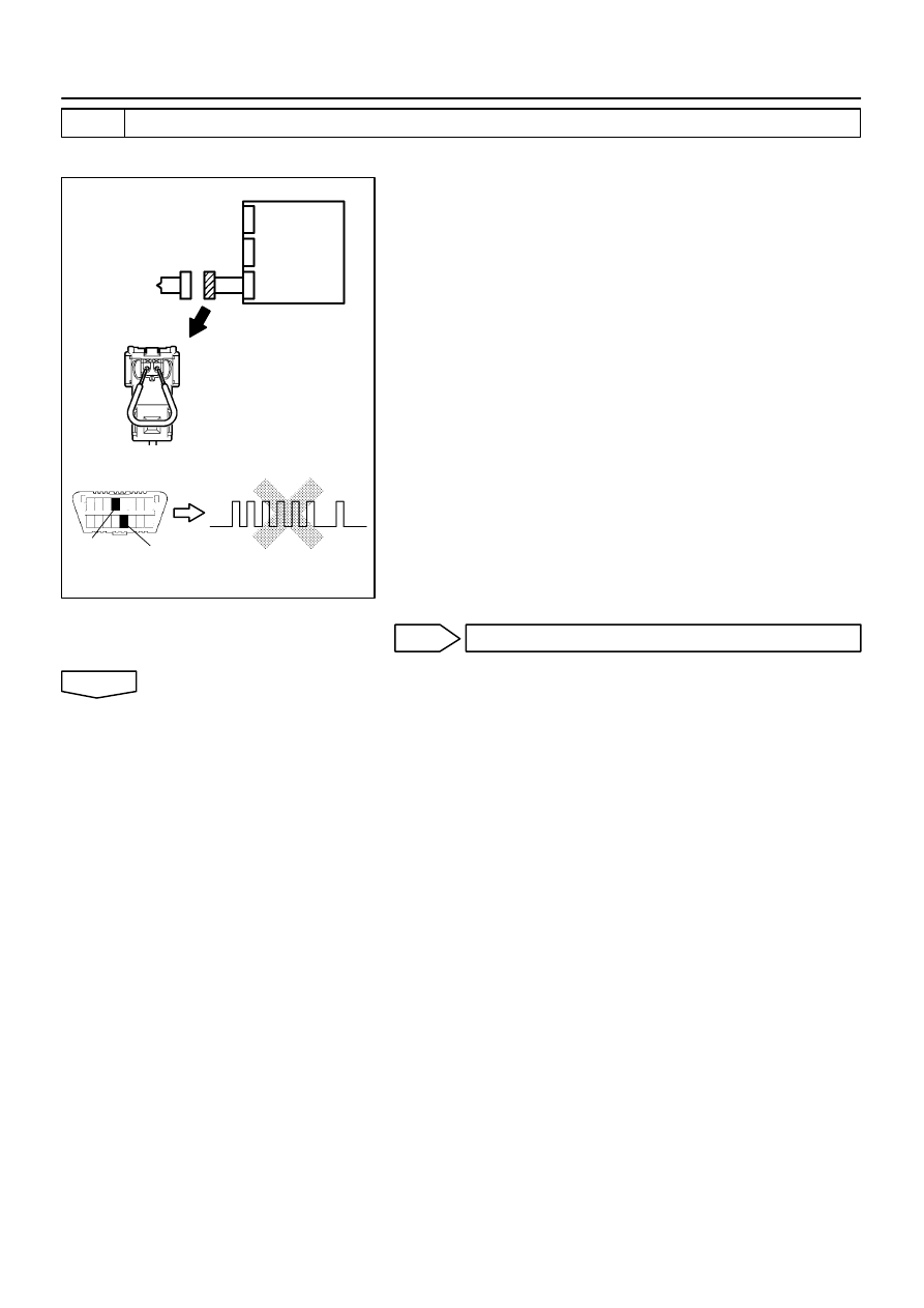
H01020
C85243
H10600 H01079
H40952
P/T Squib (RH)
DLC3
DTC B0132/61
Tc
CG
Airbag
Sensor
Assy
Center
05–502
–
DIAGNOSTICS
SUPPLEMENTAL RESTRAINT SYSTEM (April, 2003)
667
Author:
Date:
2004 COROLLA (RM1037U)
2
CHECK AIR BAG SENSOR ASSY CENTER
SST
09843–18040
(a)
Connect the connector to the airbag sensor assy center.
(b)
Using a service wire, connect PR+ and PR– of the con-
nector (on the seat belt pretensioner side) between the
airbag sensor assy center and the seat belt pretensioner
(RH).
(c)
Connect the negative (–) terminal cable to the battery,
and wait at least for 2 seconds.
(d)
Turn the ignition switch to ON, and wait at least for 20 se-
conds.
(e)
Clear the DTC stored in memory (See page
05–424
).
(f)
Turn the ignition switch to LOCK, and wait at least for 20
seconds.
(g)
Turn the ignition switch to ON, and wait at least for 20 se-
conds.
(h)
Check the DTC (See page
05–424
).
OK:
DTC B0132/61 is not output.
HINT:
Codes other than code B0132/61 may be output at this time, but
they are not relevant to this check.
NG
REPLACE AIR BAG SENSOR ASSY CENTER
OK
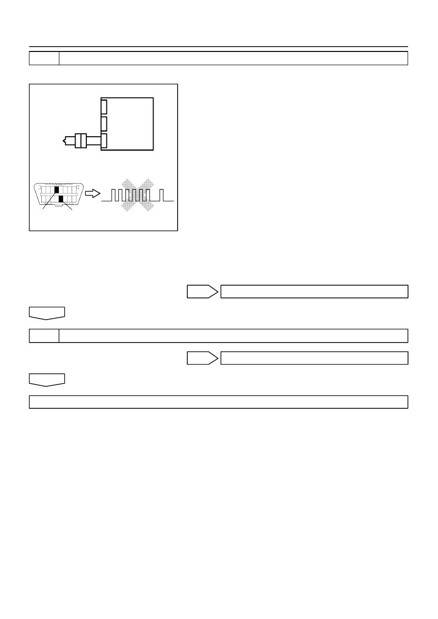
H10600
H01021
H01079
H40053
Airbag
Sensor
Assy
Center
P/T Squib (RH)
DLC3
DTC B0132/61
Tc
CG
–
DIAGNOSTICS
SUPPLEMENTAL RESTRAINT SYSTEM (April, 2003)
05–503
668
Author:
Date:
2004 COROLLA (RM1037U)
3
CHECK P/T SQUIB (RH)
SST
09843–18040
(a)
Turn the ignition switch to LOCK.
(b)
Disconnect the negative (–) terminal cable from the bat-
tery, and wait at least for 90 seconds.
(c)
Connect the seat belt pretensioner (RH) connector.
(d)
Connect the negative (–) terminal cable to the battery,
and wait at least for 2 seconds.
(e)
Turn the ignition switch to ON, and wait at least for 20 se-
conds.
(f)
Clear the DTC stored in memory (See page
05–424
).
(g)
Turn the ignition switch to LOCK, and wait at least for 20
seconds.
(h)
Turn the ignition switch to ON, and wait at least for 20 se-
conds.
(i)
Check the DTC (See page
05–424
).
OK:
DTC B0132/61 is not output.
HINT:
Codes other than code B0132/61 may be output at this time, but
they are not relevant to this check.
NG
REPLACE FRONT SEAT OUTER BELT ASSY RH
OK
4
USE SIMULATION METHOD TO CHECK
NG
Go to step 1
OK
REPLACE ALL SRS COMPONENTS INCLUDING THE WIRE HARNESS
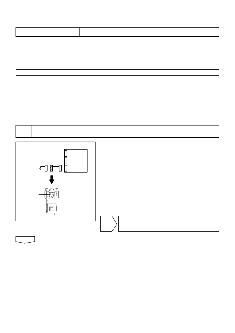
H01019
C81077
H40048
P/T Squib (RH)
PR+
PR–
Airbag
Sensor
Assy
Center
05–504
–
DIAGNOSTICS
SUPPLEMENTAL RESTRAINT SYSTEM (April, 2003)
669
Author:
Date:
2004 COROLLA (RM1037U)
DTC
B0133/62 SHORT IN P/T SQUIB (RH) CIRCUIT (TO B+)
CIRCUIT DESCRIPTION
The P/T squib (RH) circuit consists of the airbag sensor assy center and seat belt pretensioner (RH).
It causes the SRS to deploy when the SRS deployment conditions are satisfied.
DTC B0133/62 is recorded when a B+ short is detected in the P/T squib (RH) circuit.
DTC No.
DTC Detecting Condition
Trouble Area
B0133/62
Short circuit in seat belt pretensioner (RH) wire harness
(to B+)
P/T squib (RH) malfunction
Airbag sensor assy center malfunction
Seat belt pretensioner (RH)
Airbag sensor assy center
Instrument panel wire No.3
WIRING DIAGRAM
See page
05–494
.
INSPECTION PROCEDURE
1
CHECK P/T SQUIB(RH) CIRCUIT(AIRBAG SENSOR ASSY CENTER – FRONT
SEAT OUTER BELT ASSY RH)
(a)
Disconnect the negative (–) terminal cable from the bat-
tery, and wait at least for 90 seconds.
(b)
Disconnect the connectors between the airbag sensor
assy center and the seat belt pretensioner (RH).
(c)
Connect the negative (–) terminal cable to the battery,
and wait at least for 2 seconds.
(d)
Turn the ignition switch to ON.
(e)
For the connector (on the seat belt pretensioner side) be-
tween the airbag sensor assy center and the seat belt pre-
tensioner (RH), measure the voltage between PR+ and
body ground.
OK:
Voltage: Below 1V
NG
REPAIR OR REPLACE INSTRUMENT PANEL
WIRE NO.3(AIRBAG SENSOR ASSY CENTER –
FRONT SEAT OUTER BELT ASSY RH)
OK
0525W–14
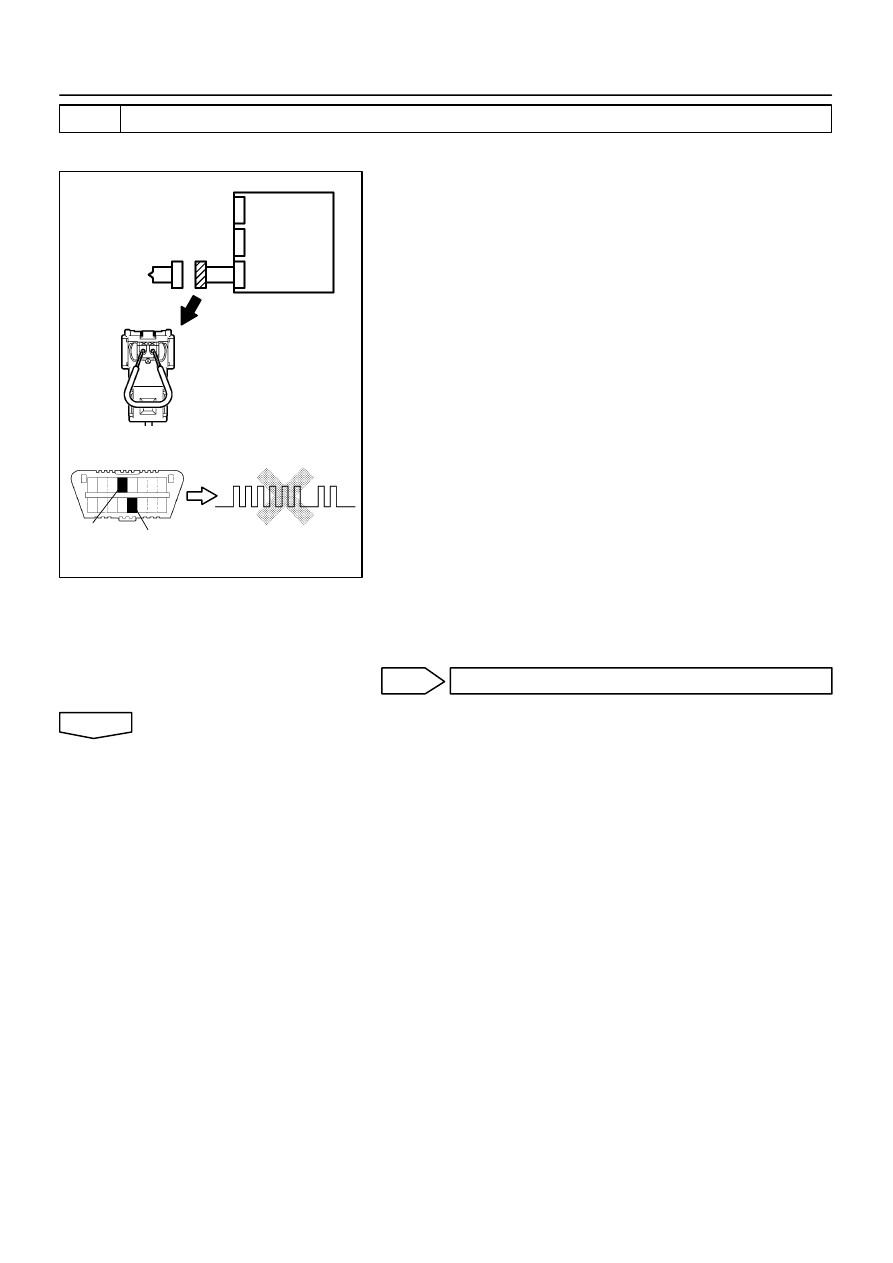
H01020
C85243
H10600 H01081
H40953
P/T Squib (RH)
DLC3
DTC B0133/62
Tc
CG
Airbag
Sensor
Assy
Center
–
DIAGNOSTICS
SUPPLEMENTAL RESTRAINT SYSTEM (April, 2003)
05–505
670
Author:
Date:
2004 COROLLA (RM1037U)
2
CHECK AIR BAG SENSOR ASSY CENTER
SST
09843–18040
(a)
Turn the ignition switch to LOCK.
(b)
Disconnect the negative (–) terminal cable from the bat-
tery, and wait at least for 90 seconds.
(c)
Connect the connector to the airbag sensor assy center.
(d)
Using a service wire, connect PR+ and PR– of the con-
nector (on the seat belt pretensioner side) between the
airbag sensor assy center and the seat belt pretensioner
(RH).
(e)
Connect the negative (–) terminal cable to the battery,
and wait at least for 2 seconds.
(f)
Turn the ignition switch to ON, and wait at least for 20 se-
conds.
(g)
Clear the DTC stored in memory (See page
05–424
).
(h)
Turn the ignition switch to LOCK, and wait at least for 20
seconds.
(i)
Turn the ignition switch to ON, and wait at least for 20 se-
conds.
(j)
Check the DTC (See page
05–424
).
OK:
DTC B0133/62 is not output.
HINT:
Codes other than code B0133/62 may be output at this time, but
they are not relevant to this check.
NG
REPLACE AIR BAG SENSOR ASSY CENTER
OK
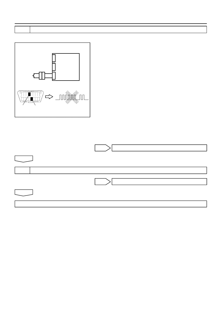
H10600
H01021
H01081
H40055
P/T Squib (RH)
DLC3
DTC B0133/62
Tc
CG
Airbag
Sensor
Assy
Center
05–506
–
DIAGNOSTICS
SUPPLEMENTAL RESTRAINT SYSTEM (April, 2003)
671
Author:
Date:
2004 COROLLA (RM1037U)
3
CHECK P/T SQUIB (RH)
SST
09843–18040
(a)
Turn the ignition switch to LOCK.
(b)
Disconnect the negative (–) terminal cable from the bat-
tery, and wait at least for 90 seconds.
(c)
Connect the seat belt pretensioner (RH) connector.
(d)
Connect the negative (–) terminal cable to the battery,
and wait at least for 2 seconds.
(e)
Turn the ignition switch to ON, and wait at least for 20 se-
conds.
(f)
Clear the DTC stored in memory (See page
05–424
).
(g)
Turn the ignition switch to LOCK, and wait at least for 20
seconds.
(h)
Turn the ignition switch to ON, and wait at least for 20 se-
conds.
(i)
Check the DTC (See page
05–424
).
OK:
DTC B0133/62 is not output.
HINT:
Codes other than code B0133/62 may be output at this time, but
they are not relevant to this check.
NG
REPLACE FRONT SEAT OUTER BELT ASSY RH
OK
4
USE SIMULATION METHOD TO CHECK
NG
Go to step 1
OK
REPLACE ALL SRS COMPONENTS INCLUDING THE WIRE HARNESS

H01454
Airbag Sensor Assy Center
P12
P/T Squib(LH)
2
A12 PL+
Y–B
1
A12 PL–
Y
1
2
–
DIAGNOSTICS
SUPPLEMENTAL RESTRAINT SYSTEM (April, 2003)
05–507
672
Author:
Date:
2004 COROLLA (RM1037U)
DTC
B0135/73 SHORT IN P/T SQUIB (LH) CIRCUIT
CIRCUIT DESCRIPTION
The P/T squib (LH) circuit consists of the airbag sensor assy center and seat belt pretensioner (LH).
It causes the SRS to deploy when the SRS deployment conditions are satisfied.
DTC B0135/73 is recorded when a short is detected in the P/T squib (LH) circuit.
DTC No.
DTC Detecting Condition
Trouble Area
B0135/73
Short circuit between PL+ wire harness and PL– wire har-
ness of squib
P/T squib (LH) malfunction
Airbag sensor assy center malfunction
Seat belt pretensioner (LH)
Airbag sensor assy center
Instrument panel wire No.3
WIRING DIAGRAM
055YZ–05
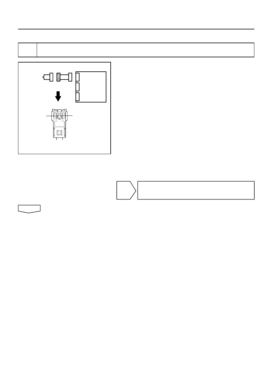
H01016
C81077
H40056
P/T Squib (RH)
PL+
PL–
Airbag
Sensor
Assy
Center
05–508
–
DIAGNOSTICS
SUPPLEMENTAL RESTRAINT SYSTEM (April, 2003)
673
Author:
Date:
2004 COROLLA (RM1037U)
INSPECTION PROCEDURE
1
CHECK P/T SQUIB(LH) CIRCUIT(AIRBAG SENSOR ASSY CENTER – FRONT SEAT
OUTER BELT ASSY LH)
(a)
Disconnect the negative (–) terminal cable from the bat-
tery, and wait at least for 90 seconds.
(b)
Disconnect the connectors between the airbag sensor
assy center and the seat belt pretensioner (LH).
HINT:
Make sure that the connector is not damaged (The lock button
is not disengaged, or the claw of the lock is not deformed or
damaged). If the damage is found, replace the wire harness.
(c)
Release the airbag activation prevention mechanism of
the connector (on the airbag sensor assy center side) be-
tween the airbag sensor assy center and the seat belt pre-
tensioner (LH) (See page
05–424
).
(d)
For the connector (on the seat belt pretensioner side) be-
tween the airbag sensor assy center and the seat belt pre-
tensioner (LH), measure the resistance between PL+ and
PL–.
OK:
Resistance: 1 M
Ω
or Higher
NG
REPAIR OR REPLACE INSTRUMENT PANEL
WIRE NO.3(AIRBAG SENSOR ASSY CENTER –
FRONT SEAT OUTER BELT ASSY LH)
OK
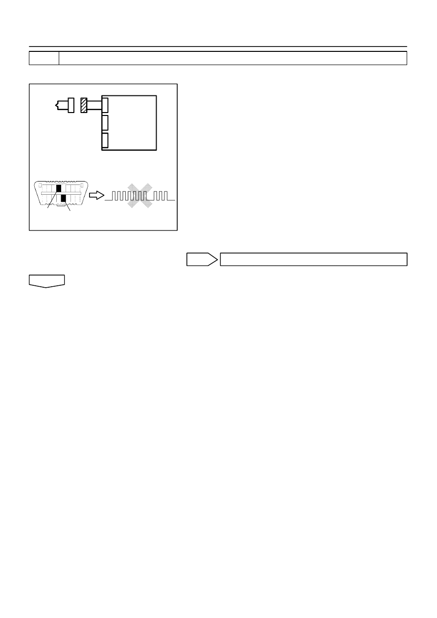
H10600
H01017
H01086
H40057
P/T Squib (LH)
DLC3
Tc
CG
DTC B0135/73
Airbag
Sensor
Assy
Center
–
DIAGNOSTICS
SUPPLEMENTAL RESTRAINT SYSTEM (April, 2003)
05–509
674
Author:
Date:
2004 COROLLA (RM1037U)
2
CHECK AIR BAG SENSOR ASSY CENTER
SST
09843–18040
(a)
Connect the connector to the airbag sensor assy center.
(b)
Connect the negative (–) terminal cable to the battery,
and wait at least for 2 seconds.
(c)
Turn the ignition switch to ON, and wait at least for 20 se-
conds.
(d)
Clear the DTC stored in memory (See page
05–424
).
(e)
Turn the ignition switch to LOCK, and wait at least for 20
seconds.
(f)
Turn the ignition switch to ON, and wait at least for 20 se-
conds.
(g)
Check the DTC (See page
05–424
).
OK:
DTC B0135/73 is not output.
HINT:
Codes other than code B0135/73 may be output at this time, but
they are not relevant to this check.
NG
REPLACE AIR BAG SENSOR ASSY CENTER
OK
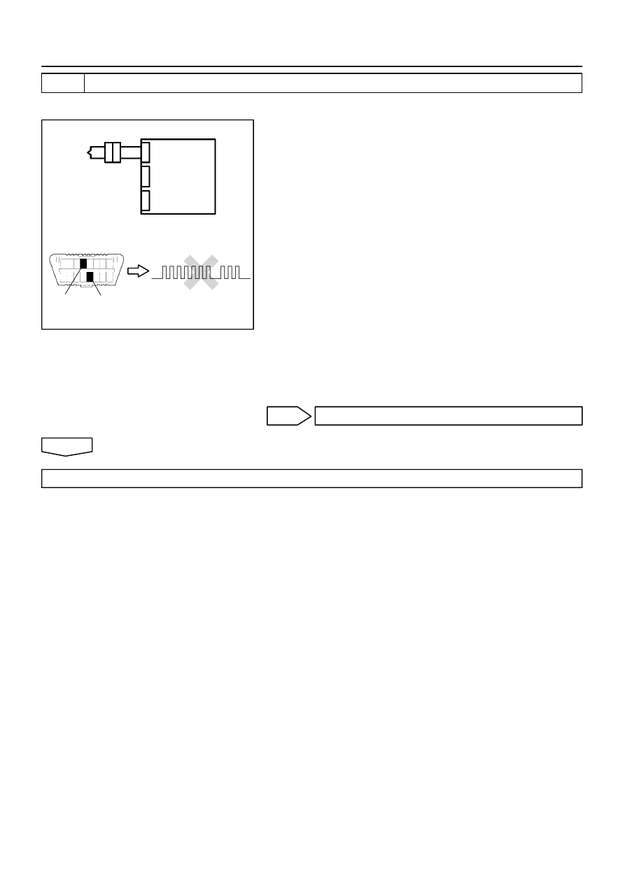
H10600 H01086
H01018
H40058
Airbag
Sensor
Assy
Center
P/T Squib (LH)
DLC3
Tc
CG
DTC B0135/73
05–510
–
DIAGNOSTICS
SUPPLEMENTAL RESTRAINT SYSTEM (April, 2003)
675
Author:
Date:
2004 COROLLA (RM1037U)
3
CHECK P/T SQUIB (LH)
SST
09843–18040
(a)
Turn the ignition switch to LOCK.
(b)
Disconnect the negative (–) terminal cable from the bat-
tery, and wait at least for 90 seconds.
(c)
Connect the seat belt pretensioner (LH) connector.
(d)
Connect the negative (–) terminal cable to the battery,
and wait at least for 2 seconds.
(e)
Turn the ignition switch to ON, and wait at least for 20 se-
conds.
(f)
Clear the DTC stored in memory (See page
05–424
).
(g)
Turn the ignition switch to LOCK, and wait at least for 20
seconds.
(h)
Turn the ignition switch to ON, and wait at least for 20 se-
conds.
(i)
Check the DTC (See page
05–424
).
OK:
DTC B0135/73 is not output.
HINT:
Codes other than code B0135/73 may be output at this time, but
they are not relevant to this check.
NG
REPLACE FRONT SEAT OUTER BELT ASSY LH
OK
USE SIMULATION METHOD TO CHECK
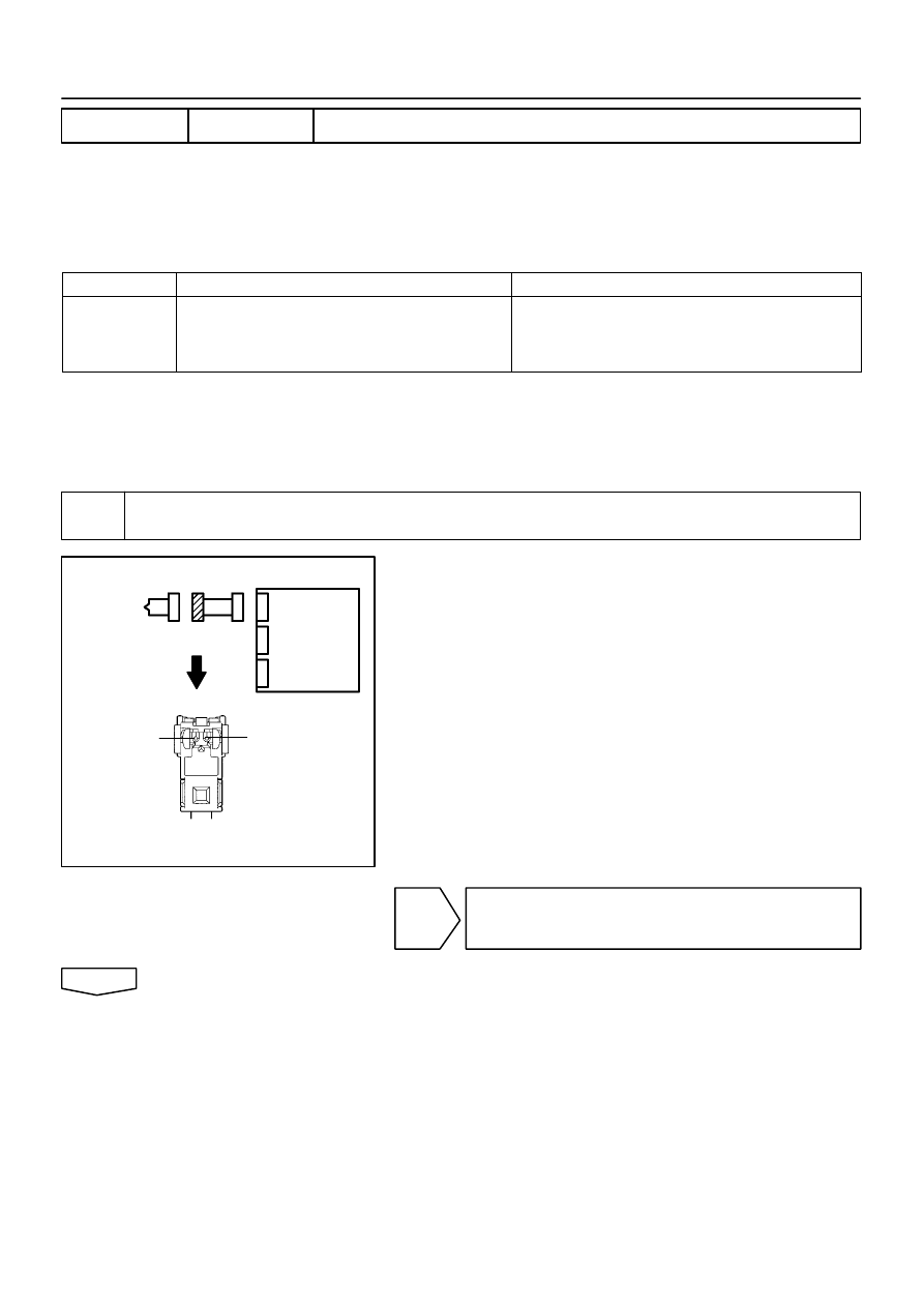
H01016
C81077
H40056
P/T Squib (LH)
PL+
PL–
Airbag
Sensor
Assy
Center
–
DIAGNOSTICS
SUPPLEMENTAL RESTRAINT SYSTEM (April, 2003)
05–511
676
Author:
Date:
2004 COROLLA (RM1037U)
DTC
B0136/74 OPEN IN P/T SQUIB (LH) CIRCUIT
CIRCUIT DESCRIPTION
The P/T squib circuit (LH) consists of the airbag sensor assy center and seat belt pretensioner (LH).
It causes the SRS to deploy when the SRS deployment conditions are satisfied.
DTC B0136/74 is recorded when an open is detected in the P/T squib (LH) circuit.
DTC No.
DTC Detecting Condition
Trouble Area
B0136/74
Open circuit in PL+ wire harness or PL– wire harness of
squib
P/T squib (LH) malfunction
Airbag sensor assy center malfunction
Seat belt pretensioner (LH)
Airbag sensor assy center
Instrument panel wire No.3
WIRING DIAGRAM
See page
05–507
.
INSPECTION PROCEDURE
1
CHECK P/T SQUIB(LH) CIRCUIT(AIRBAG SENSOR ASSY CENTER – FRONT SEAT
OUTER BELT ASSY LH)
(a)
Disconnect the negative (–) terminal cable from the bat-
tery, and wait at least for 90 seconds.
(b)
Disconnect the connectors between the airbag sensor
assy center and the seat belt pretensioner (LH).
(c)
For the connector (on the seat belt pretensioner side) be-
tween the airbag sensor assy center and the seat belt pre-
tensioner (LH), measure the resistance between PL+ and
PL–.
OK:
Resistance: Below 1
Ω
NG
REPAIR OR REPLACE INSTRUMENT PANEL
WIRE NO.3(AIRBAG SENSOR ASSY CENTER –
FRONT SEAT OUTER BELT ASSY LH)
OK
055Z0–05
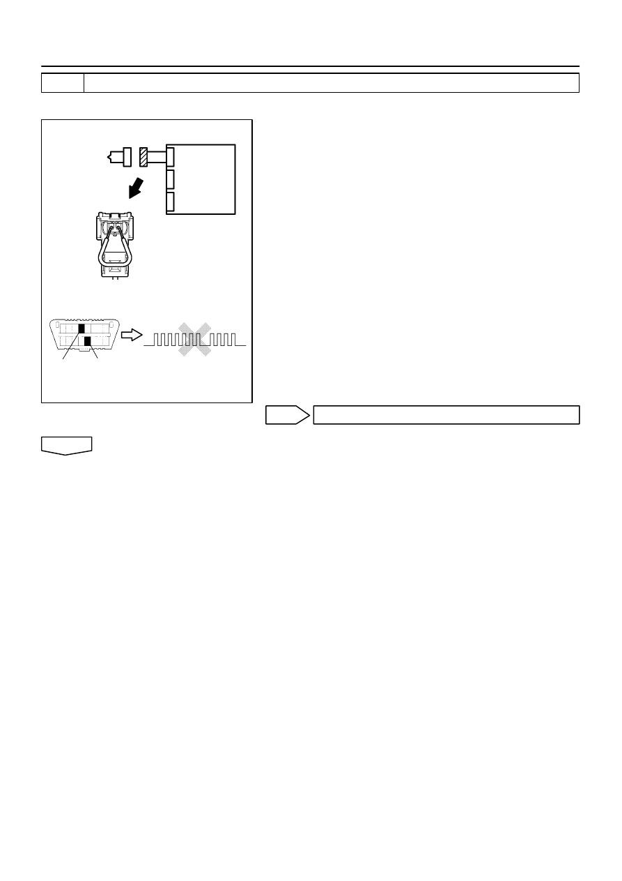
H01017
C85243
H10600 H01087
H40950
P/T Squib (LH)
DLC3
Tc
CG
DTC B0136/74
Airbag
Sensor
Assy
Center
05–512
–
DIAGNOSTICS
SUPPLEMENTAL RESTRAINT SYSTEM (April, 2003)
677
Author:
Date:
2004 COROLLA (RM1037U)
2
CHECK AIR BAG SENSOR ASSY CENTER
SST
09843–18040
(a)
Connect the connector to the airbag sensor assy center.
(b)
Using a service wire, connect PL+ and PL– of the connec-
tor (on the seat belt pretensioner side) between the airbag
sensor assy center and the seat belt pretensioner (LH).
(c)
Connect the negative (–) terminal cable to the battery,
and wait at least for 2 seconds.
(d)
Turn the ignition switch to ON, and wait at least for 20 se-
conds.
(e)
Clear the DTC stored in memory (See page
05–424
).
(f)
Turn the ignition switch to LOCK, and wait at least for 20
seconds.
(g)
Turn the ignition switch to ON, and wait at least for 20 se-
conds.
(h)
Check the DTC (See page
05–424
).
OK:
DTC B0136/74 is not output.
HINT:
Codes other than code B0136/74 may be output at this time, but
they are not relevant to this check.
NG
REPLACE AIR BAG SENSOR ASSY CENTER
OK
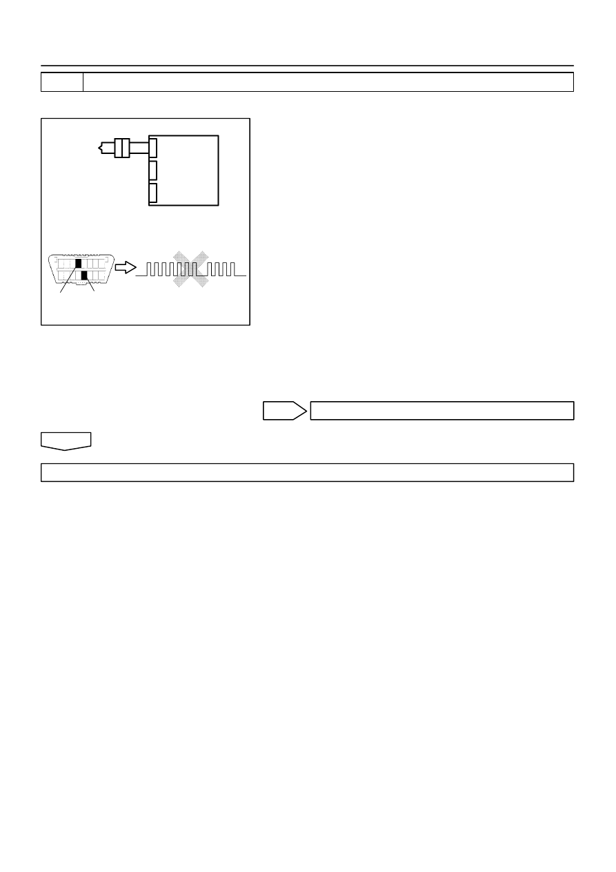
H10600
H01018
H01087
H40060
P/T Squib (LH)
DLC3
CG
DTC B0136/74
Tc
Airbag
Sensor
Assy
Center
–
DIAGNOSTICS
SUPPLEMENTAL RESTRAINT SYSTEM (April, 2003)
05–513
678
Author:
Date:
2004 COROLLA (RM1037U)
3
CHECK P/T SQUIB (LH)
SST
09843–18040
(a)
Turn the ignition switch to LOCK.
(b)
Disconnect the negative (–) terminal cable from the bat-
tery, and wait at least for 90 seconds.
(c)
Connect the seat belt pretensioner (LH) connector.
(d)
Connect the negative (–) terminal cable to the battery,
and wait at least for 2 seconds.
(e)
Turn the ignition switch to ON, and wait at least for 20 se-
conds.
(f)
Clear the DTC stored in memory (See page
05–424
).
(g)
Turn the ignition switch to LOCK, and wait at least for 20
seconds.
(h)
Turn the ignition switch to ON, and wait at least for 20 se-
conds.
(i)
Check the DTC (See page
05–424
).
OK:
DTC B0136/74 is not output.
HINT:
Codes other than code B0136/74 may be output at this time, but
they are not relevant to this check.
NG
REPLACE FRONT SEAT OUTER BELT ASSY LH
OK
USE SIMULATION METHOD TO CHECK
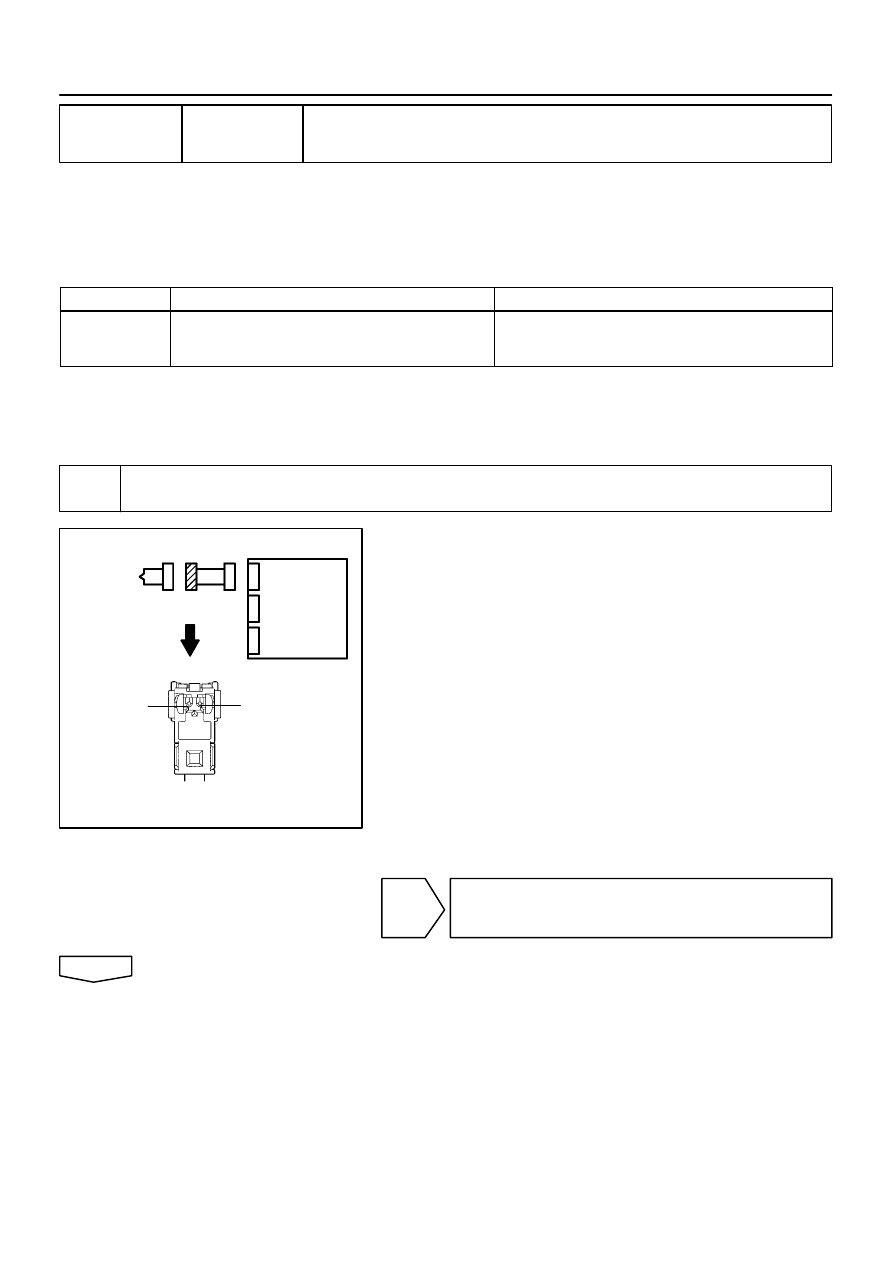
H01016
C81077
H40056
P/T Squib (LH)
PL+
PL–
Airbag
Sensor
Assy
Center
05–514
–
DIAGNOSTICS
SUPPLEMENTAL RESTRAINT SYSTEM (April, 2003)
679
Author:
Date:
2004 COROLLA (RM1037U)
DTC
B0137/71 SHORT IN P/T SQUIB (LH) CIRCUIT (TO
GROUND)
CIRCUIT DESCRIPTION
The P/T squib (LH) circuit consists of the airbag sensor assy center and seat belt pretensioner (LH).
It causes the SRS to deploy when the SRS deployment conditions are satisfied.
DTC B0137/71 is recorded when a ground short is detected in the P/T squib (LH) circuit.
DTC No.
DTC Detecting Condition
Trouble Area
B0137/71
Short circuit in P/T squib (LH) wire harness (to ground)
P/T squib (LH) malfunction
Airbag sensor assy center malfunction
Seat belt pretensioner (LH)
Airbag sensor assy center
Instrument panel wire No.3
WIRING DIAGRAM
See page
05–507
.
INSPECTION PROCEDURE
1
CHECK P/T SQUIB(LH) CIRCUIT(AIRBAG SENSOR ASSY CENTER – FRONT SEAT
OUTER BELT ASSY LH)
(a)
Disconnect the negative (–) terminal cable from the bat-
tery, and wait at least for 90 seconds.
(b)
Disconnect the connectors between the airbag sensor
assy center and the seat belt pretensioner (LH).
(c)
For the connector (on the seat belt pretensioner side) be-
tween the airbag sensor assy center and the seat belt pre-
tensioner (LH), measure the resistance between PL+ and
body ground.
OK:
Resistance: 1 M
Ω
or Higher
NG
REPAIR OR REPLACE INSTRUMENT PANEL
WIRE NO.3(AIRBAG SENSOR ASSY CENTER –
FRONT SEAT OUTER BELT ASSY LH)
OK
0525Z–14

H01017
C85243
H10600 H01084
H40954
P/T Squib (LH)
DLC3
Tc
CG
DTC B0137/71
Airbag
Sensor
Assy
Center
–
DIAGNOSTICS
SUPPLEMENTAL RESTRAINT SYSTEM (April, 2003)
05–515
680
Author:
Date:
2004 COROLLA (RM1037U)
2
CHECK AIR BAG SENSOR ASSY CENTER
SST
09843–18040
(a)
Connect the connector to the airbag sensor assy center.
(b)
Using a service wire, connect PL+ and PL– of the connec-
tor (on the seat belt pretensioner side) between the airbag
sensor assy center and the seat belt pretensioner (LH).
(c)
Connect the negative (–) terminal cable to the battery,
and wait at least for 2 seconds.
(d)
Turn the ignition switch to ON, and wait at least for 20 se-
conds.
(e)
Clear the DTC stored in memory (See page
05–424
).
(f)
Turn the ignition switch to LOCK, and wait at least for 20
seconds.
(g)
Turn the ignition switch to ON, and wait at least for 20 se-
conds.
(h)
Check the DTC (See page
05–424
).
OK:
DTC B0137/71 is not output.
HINT:
Codes other than code B0137/71 may be output at this time, but
they are not relevant to this check.
NG
REPLACE AIR BAG SENSOR ASSY CENTER
OK
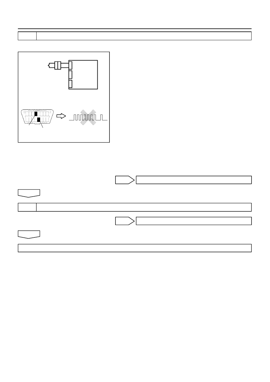
H10600
H01018
H01084
H40062
P/T Squib (LH)
Airbag
Sensor
Assy
Center
DLC3
CG
DTC B0137/71
Tc
05–516
–
DIAGNOSTICS
SUPPLEMENTAL RESTRAINT SYSTEM (April, 2003)
681
Author:
Date:
2004 COROLLA (RM1037U)
3
CHECK P/T SQUIB (LH)
SST
09843–18040
(a)
Turn the ignition switch to LOCK.
(b)
Disconnect the negative (–) terminal cable from the bat-
tery, and wait at least for 90 seconds.
(c)
Connect the seat belt pretensioner (LH) connector.
(d)
Connect the negative (–) terminal cable to the battery,
and wait at least for 2 seconds.
(e)
Turn the ignition switch to ON, and wait at least for 20 se-
conds.
(f)
Clear the DTC stored in memory (See page
05–424
).
(g)
Turn the ignition switch to LOCK, and wait at least for 20
seconds.
(h)
Turn the ignition switch to ON, and wait at least for 20 se-
conds.
(i)
Check the DTC (See page
05–424
).
OK:
DTC B0137/71 is not output.
HINT:
Codes other than code B0137/71 may be output at this time, but
they are not relevant to this check.
NG
REPLACE FRONT SEAT OUTER BELT ASSY LH
OK
4
USE SIMULATION METHOD TO CHECK
NG
Go to step 1
OK
REPLACE ALL SRS COMPONENTS INCLUDING THE WIRE HARNESS
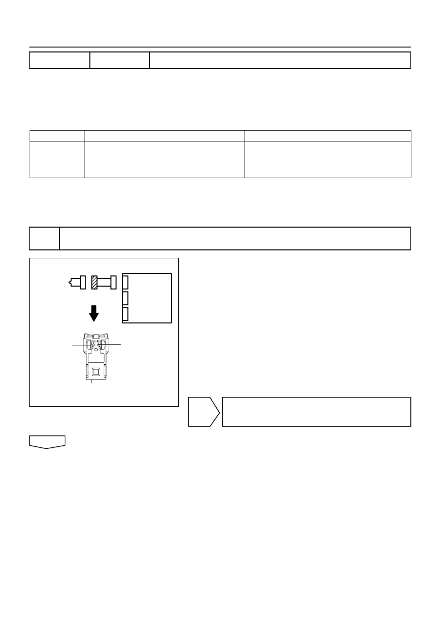
H01016
C81077
H40056
P/T Squib (LH)
PL+
PL–
Airbag
Sensor
Assy
Center
–
DIAGNOSTICS
SUPPLEMENTAL RESTRAINT SYSTEM (April, 2003)
05–517
682
Author:
Date:
2004 COROLLA (RM1037U)
DTC
B0138/72 SHORT IN P/T SQUIB (LH) CIRCUIT (TO B+)
CIRCUIT DESCRIPTION
The P/T squib (LH) circuit consists of the airbag sensor assy center and seat belt pretensioner (LH).
It causes the SRS to deploy when the SRS deployment conditions are satisfied.
DTC B0138/72 is recorded when a B+ short is detected in the P/T squib (LH) circuit.
DTC No.
DTC Detecting Condition
Trouble Area
B0138/72
Short circuit in seat belt pretensioner (LH) wire harness
(to B+)
P/T squib (LH) malfunction
Airbag sensor assy center malfunction
Seat belt pretensioner (LH)
Airbag sensor assy center
Instrument panel wire No.3
WIRING DIAGRAM
See page
05–507
.
INSPECTION PROCEDURE
1
CHECK P/T SQUIB(LH) CIRCUIT(AIRBAG SENSOR ASSY CENTER – FRONT SEAT
OUTER BELT ASSY LH)
(a)
Disconnect the negative (–) terminal cable from the bat-
tery, and wait at least for 90 seconds.
(b)
Disconnect the connectors between the airbag sensor
assy center and the seat belt pretensioner (LH).
(c)
Connect the negative (–) terminal cable to the battery,
and wait at least for 2 seconds.
(d)
Turn the ignition switch to ON.
(e)
For the connector (on the seat belt pretensioner side) be-
tween the airbag sensor assy center and the seat belt pre-
tensioner (LH), measure the voltage between PL+ and
body ground.
OK:
Voltage: Below 1V
NG
REPAIR OR REPLACE INSTRUMENT PANEL
WIRE NO.3(AIRBAG SENSOR ASSY CENTER –
FRONT SEAT OUTER BELT ASSY LH)
OK
05260–14
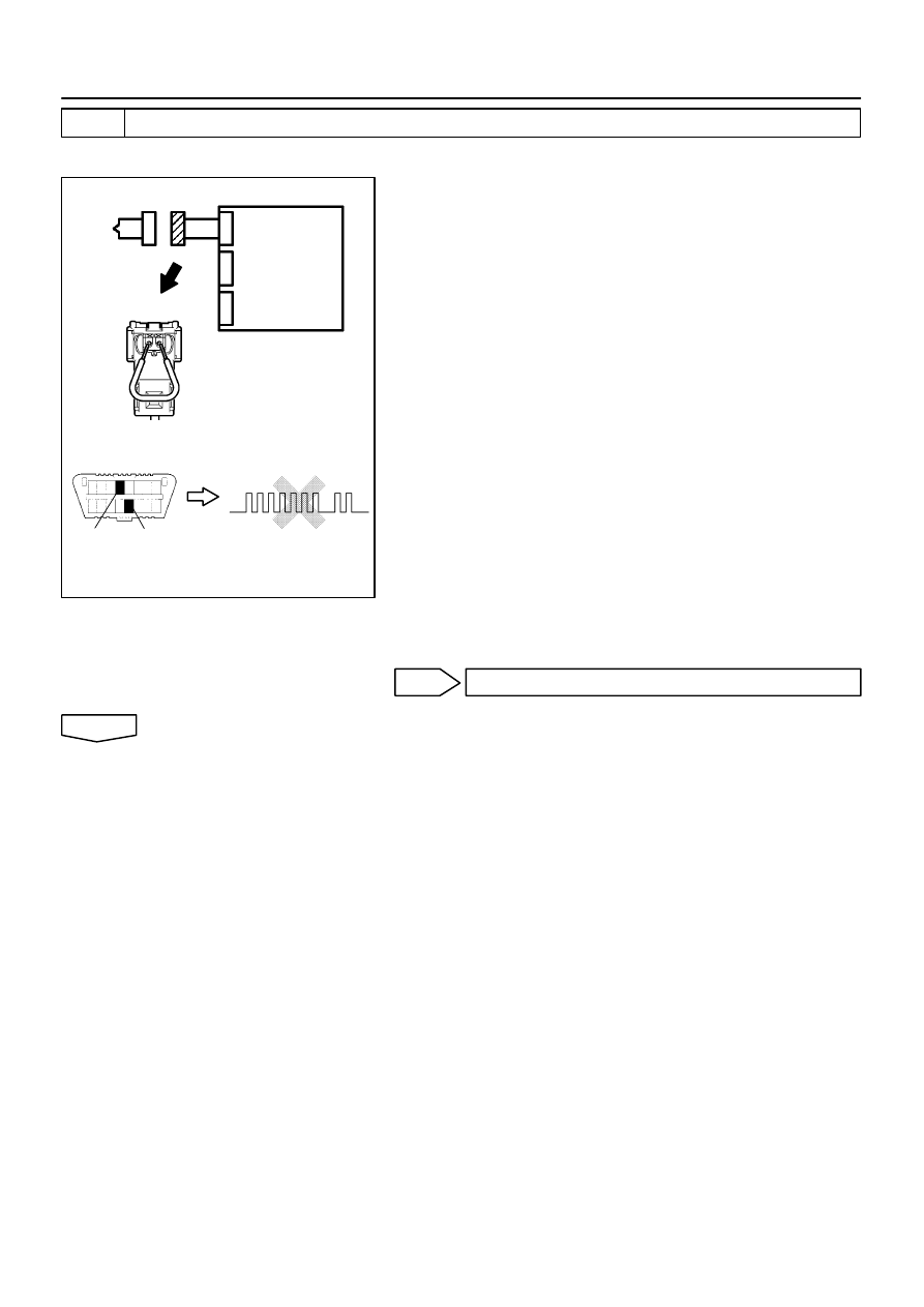
H01017
C85243
H10600 H01085
H40957
P/T Squib (LH)
DLC3
Tc
CG
DTC B0138/72
Airbag
Sensor
Assy
Center
05–518
–
DIAGNOSTICS
SUPPLEMENTAL RESTRAINT SYSTEM (April, 2003)
683
Author:
Date:
2004 COROLLA (RM1037U)
2
CHECK AIR BAG SENSOR ASSY CENTER
SST
09843–18040
(a)
Turn the ignition switch to LOCK.
(b)
Disconnect the negative (–) terminal cable from the bat-
tery and wait at least for 90 seconds.
(c)
Connect the connector to the airbag sensor assy center.
(d)
Using a service wire, connect PL+ and PL– of the connec-
tor (on the seat belt pretensioner side) between the airbag
sensor assy center and the seat belt pretensioner (LH).
(e)
Connect the negative (–) terminal cable to the battery,
and wait at least for 2 seconds.
(f)
Turn the ignition switch to ON, and wait at least for 20 se-
conds.
(g)
Clear the DTC stored in memory (See page
05–424
).
(h)
Turn the ignition switch to LOCK, and wait at least for 20
seconds.
(i)
Turn the ignition switch to ON, and wait at least for 20 se-
conds.
(j)
Check the DTC (See page
05–424
).
OK:
DTC B0138/72 is not output.
HINT:
Codes other than code B0138/72 may be output at this time, but
they are not relevant to this check.
NG
REPLACE AIR BAG SENSOR ASSY CENTER
OK
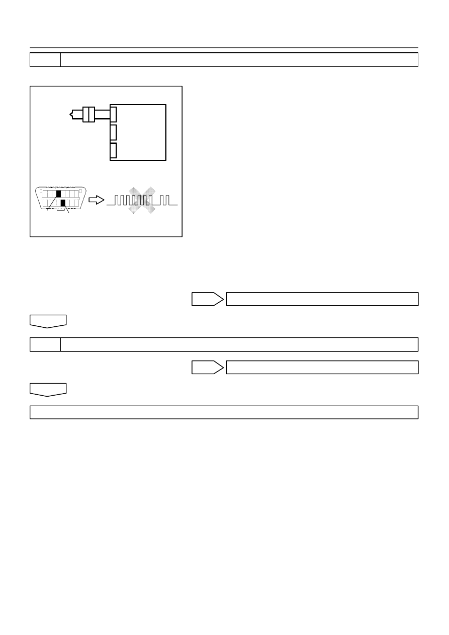
H10600
H01018
H01085
H40064
P/T Squib (LH)
DLC3
DTC B0138/72
CG
Tc
Airbag
Sensor
Assy
Center
–
DIAGNOSTICS
SUPPLEMENTAL RESTRAINT SYSTEM (April, 2003)
05–519
684
Author:
Date:
2004 COROLLA (RM1037U)
3
CHECK P/T SQUIB (LH)
SST
09843–18040
(a)
Turn the ignition switch to LOCK.
(b)
Disconnect the negative (–) terminal cable from the bat-
tery, and wait at least for 90 seconds.
(c)
Connect the seat belt pretensioner (LH) connector.
(d)
Connect the negative (–) terminal cable to the battery,
and wait at least for 2 seconds.
(e)
Turn the ignition switch to ON, and wait at least for 20 se-
conds.
(f)
Clear the DTC stored in memory (See page
05–424
).
(g)
Turn the ignition switch to LOCK, and wait at least for 20
seconds.
(h)
Turn the ignition switch to ON, and wait at least for 20 se-
conds.
(i)
Check the DTC (See page
05–424
).
OK:
DTC B0138/72 is not output.
HINT:
Codes other than code B0138/72 may be output at this time, but
they are not relevant to this check.
NG
REPLACE FRONT SEAT OUTER BELT ASSY LH
OK
4
USE SIMULATION METHOD TO CHECK
NG
Go to step 1
OK
REPLACE ALL SRS COMPONENTS INCLUDING THE WIRE HARNESS
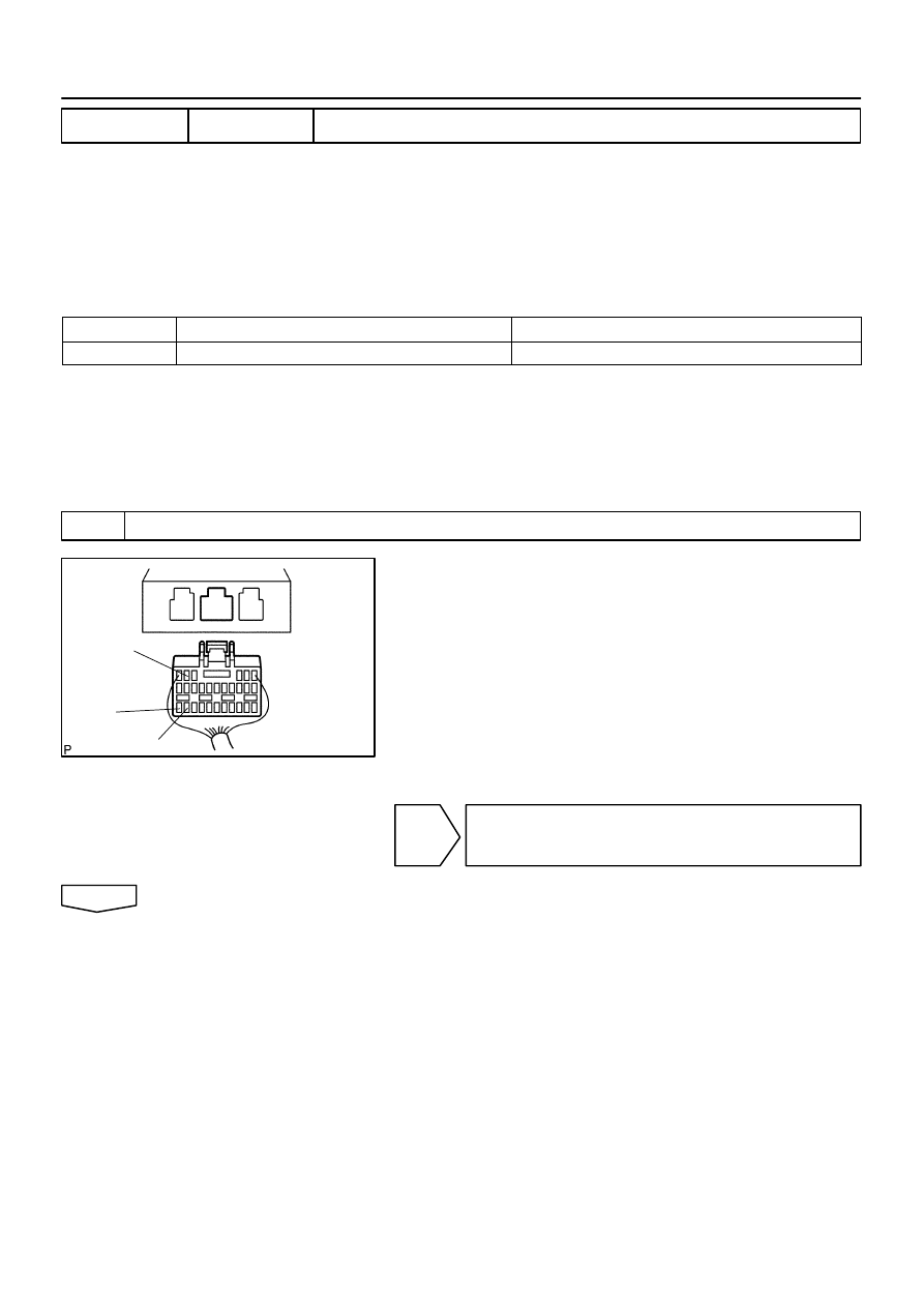
H40065
IG2
E2
E1
05–520
–
DIAGNOSTICS
SUPPLEMENTAL RESTRAINT SYSTEM (April, 2003)
685
Author:
Date:
2004 COROLLA (RM1037U)
DTC
B1100/31 AIRBAG SENSOR ASSY MALFUNCTION
CIRCUIT DESCRIPTION
The airbag sensor assy center consists of a airbag sensor assy center, safing sensor, drive circuit, diagnosis
circuit and ignition control, etc.
It receives signals from the airbag sensor, judges whether or not the SRS must be activated, and detects
diagnosis system malfunction.
DTC B1100/31 is recorded when occurrence of a malfunction in the airbag sensor assy center is detected.
DTC No.
DTC Detecting Condition
Trouble Area
B1100/31
Airbag sensor assy center malfunction
Airbag sensor assy center
INSPECTION PROCEDURE
HINT:
When a malfunction code other than code B1100/31 is displayed at the same time, first repair the malfunction
indicated by the malfunction code other than code B1100/31.
INSPECTION PROCEDURE
1
CHECK VOLTAGE AT IG2 OF AIRBAG SENSOR ASSY CENTER
(a)
Disconnect the negative (–) terminal cable from the bat-
tery, and wait at least for 90 seconds.
(b)
Disconnect the connector of the airbag sensor assy cen-
ter.
(c)
Connect the negative (–) terminal cable to the battery,
and wait at least for 2 seconds.
(d)
Turn the ignition switch to ON.
(e)
Measure the voltage between E1 (E2) and IG2 of the air-
bag sensor assy center connector.
OK:
Voltage: 10 – 14 V
NG
CHECK CHECK THAT AN ABNORMALITY
OCCURS ON THE BATTERY AND CHARGING
SYSTEM
OK
05261–09
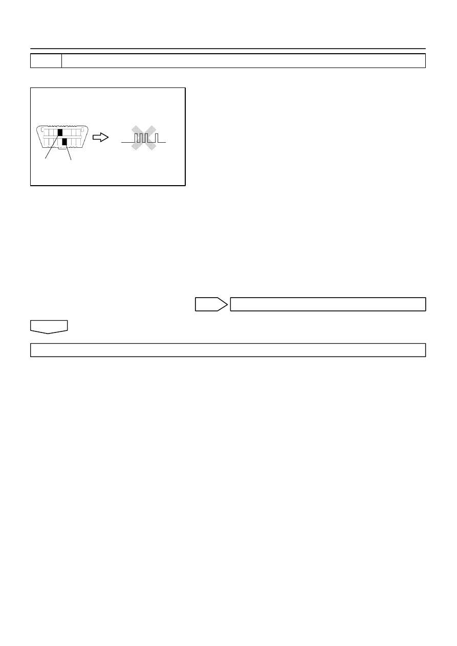
H10600
H41086
DLC3
DTC B1100/31
CG
Tc
–
DIAGNOSTICS
SUPPLEMENTAL RESTRAINT SYSTEM (April, 2003)
05–521
686
Author:
Date:
2004 COROLLA (RM1037U)
2
CHECK AIR BAG SENSOR ASSY CENTER
SST
09843–18040
(a)
Turn the ignition switch to LOCK.
(b)
Disconnect the negative (–) terminal cable from the bat-
tery, and wait at least for 90 seconds.
(c)
Connect the connectors of all the SRS components.
(d)
Connect the negative (–) terminal cable to the battery,
and wait at least for 2 seconds.
(e)
Turn the ignition switch to ON, and wait at least for 20 se-
conds.
(f)
Clear the DTC stored in memory (See page
05–424
).
(g)
Turn the ignition switch to LOCK, and wait at least for 20
seconds.
(h)
Turn the ignition switch to ON, and wait at least for 20 se-
conds.
(i)
Check the DTC (See page
05–424
).
OK:
DTC B1100/31 is not output.
HINT:
Codes other than code B1100/31 may be output at this time, but
they are not relevant to this check.
NG
REPLACE AIR BAG SENSOR ASSY CENTER
OK
USE SIMULATION METHOD TO CHECK
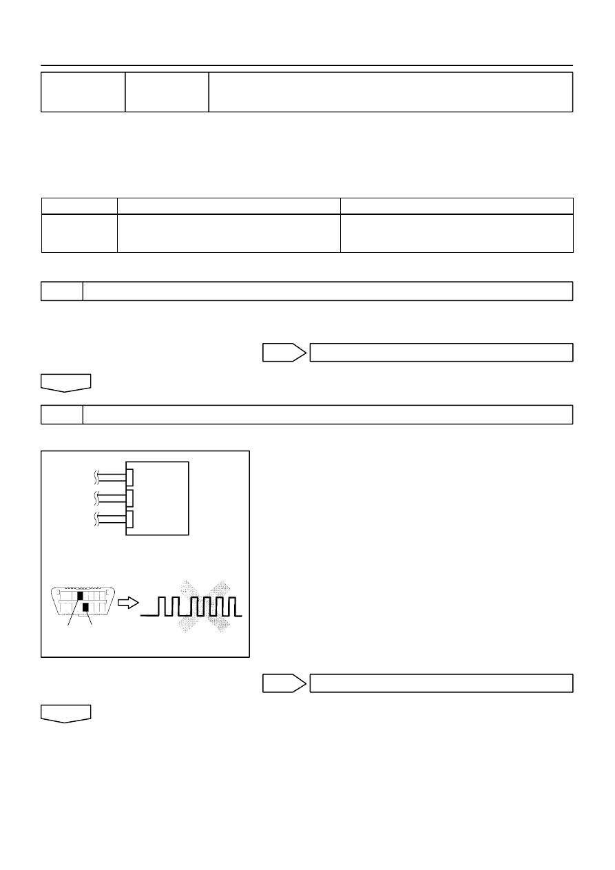
H40997
DLC3
DTC B1135/24
CG
Tc
Airbag
Sensor
Assy
Center
05–522
–
DIAGNOSTICS
SUPPLEMENTAL RESTRAINT SYSTEM (April, 2003)
687
Author:
Date:
2004 COROLLA (RM1037U)
DTC
B1135/24 HARF CONNECTION IN AIRBAG SENSOR
ASSY CONNECTOR
CIRCUIT DESCRIPTION
The airbag sensor assy center detects partial connection of connector.
DTC B1135/24 is recorded when the airbag sensor assy center detects an open in the electrical connection
check mechanism of the airbag sensor connector or in the airbag sensor circuit.
DTC No.
DTC Detecting Condition
Trouble Area
B1135/24
Malfunction of electrical connection check mechanism of
airbag sensor assy center connector
Airbag sensor assy center malfunction
Electrical connection check mechanism
Airbag sensor assy center
INSPECTION PROCEDURE
1
CHECK AIRBAG SENSOR ASSY CENTER CONNECTOR
(a)
Disconnect negative (–) terminal cable from the battery, and wait at least for 90 seconds.
(b)
Check the connection of the airbag sensor assy center connectors.
NG
CONNECT CONNECTORS
OK
2
CHECK AIR BAG SENSOR ASSY CENTER
SST
09843–18040
(a)
Connect the negative (–) terminal cable to the battery,
and wait at least for 2 seconds.
(b)
Turn the ignition switch to ON, and wait at least for 20 se-
conds.
(c)
Clear the DTC stored in memory (See page
05–424
).
(d)
Turn the ignition switch to LOCK, and wait at least for 20
seconds.
(e)
Turn the ignition switch to ON, and wait at least for 20 se-
conds.
(f)
Check the DTC (See page
05–424
).
OK:
DTC B1135/24 is not output.
HINT:
Codes other than code B1135/24 may be output at this time, but
they are not relevant to this check.
OK
USE SIMULATION METHOD TO CHECK
NG
055Z3–05
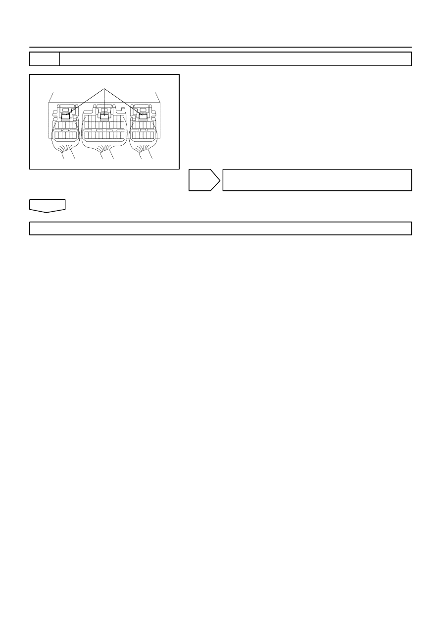
H40441
Disconnection Detection Pin
–
DIAGNOSTICS
SUPPLEMENTAL RESTRAINT SYSTEM (April, 2003)
05–523
688
Author:
Date:
2004 COROLLA (RM1037U)
3
CHECK PERFORM A VISUAL CHECK OF THE DISCONNECTION DETECTION PIN
(a)
Turn the ignition switch to LOCK.
(b)
Disconnect the negative (–) terminal cable from the bat-
tery, and wait at least for 90 seconds.
(c)
With 3 connectors connected to the airbag sensor assy
center, place tester leads onto any 2 of 3 disconnection
detection pins and check for continuity.
OK:
Continuity
NG
REPAIR OR REPLACE AIRBAG SENSOR ASSY
CENTER CONNECTOR
OK
REPLACE AIR BAG SENSOR ASSY CENTER

H01450
S11
Side Airbag Sensor Assy (RH)
Airbag Sensor Assy Center
GR
LG
L–Y
P
ESR
SSR–
FSR
VUPR
4
3
2
1
A14
7
10
9
12
ESR
SSR–
FSR
VUPR
A14
A14
A14
05–524
–
DIAGNOSTICS
SUPPLEMENTAL RESTRAINT SYSTEM (April, 2003)
689
Author:
Date:
2004 COROLLA (RM1037U)
DTC
B1140/32 SIDE AIRBAG SENSOR ASSY (RH)
MALFUNCTION
CIRCUIT DESCRIPTION
The side airbag sensor assy (RH) circuit consists of the diagnosis circuit and lateral deceleration sensor, etc.
It receives signals from the lateral deceleration sensor, judges whether or not the SRS must be activated,
and detects diagnosis system malfunction.
DTC B1140/32 is recorded when occurrence of a malfunction in the side airbag sensor assy (RH) is detected.
DTC No.
DTC Detecting Condition
Trouble Area
B1140/32
Short circuit in wire harness of side airbag sensor RH
(to ground)
Short circuit in wire harness of side airbag sensor RH
(to B+)
Open circuit in wire harness of side airbag sensor RH
Side airbag sensor assy RH malfunction
Airbag sensor assy center malfunction
Side airbag sensor assy (RH)
Airbag sensor assy center
Instrument panel wire No.3
WIRING DIAGRAM
055Z6–04
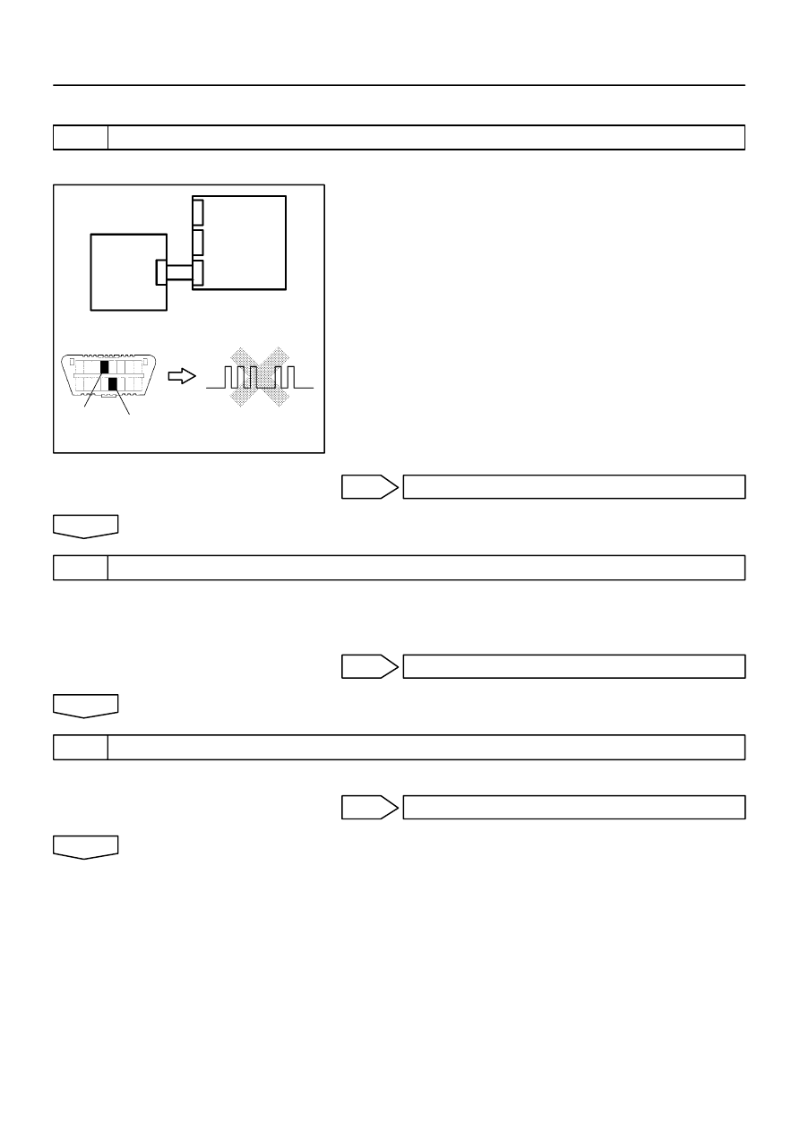
H10600
H01012
H01065
H40442
Side
Airbag
Sensor
Assy RH
Airbag
Sensor
Assy
Center
DLC3
CG
Tc
DTC B1140/32
–
DIAGNOSTICS
SUPPLEMENTAL RESTRAINT SYSTEM (April, 2003)
05–525
690
Author:
Date:
2004 COROLLA (RM1037U)
INSPECTION PROCEDURE
1
CHECK SIDE AIR BAG SENSOR ASSY RH
SST
09843–18040
(a)
Connect the negative (–) terminal cable to the battery,
and wait at least for 2 seconds.
(b)
Turn the ignition switch to ON, and wait at least for 20 se-
conds.
(c)
Clear the DTC stored in memory (See page
05–424
).
(d)
Turn the ignition switch to LOCK, and wait at least for 20
seconds.
(e)
Turn the ignition switch to ON, and wait at least for 20 se-
conds.
(f)
Check the DTC (See page
05–424
).
OK:
DTC B1140/32 is not output.
HINT:
Codes other than code B1140/32 may be output at this time, but
they are not relevant to this check.
OK
USE SIMULATION METHOD TO CHECK
NG
2
CHECK AIRBAG SENSOR ASSY CENTER CONNECTOR
(a)
Turn the ignition switch to LOCK.
(b)
Disconnect the negative (–) terminal cable from the battery, and wait at least for 90 seconds.
(c)
Check that the connectors is properly connected to the airbag sensor assy center.
NG
CONNECT CONNECTORS
OK
3
CHECK SIDE AIRBAG SENSOR ASSY CONNECTOR
(a)
Check that the connector is properly connected to the side airbag sensor assy (RH).
NG
CONNECT CONNECTORS
OK
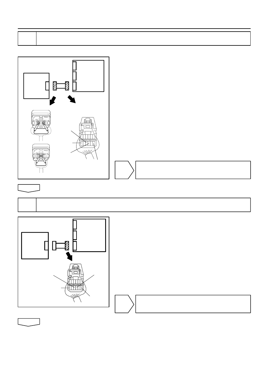
H01015
C82942
C91384
C91385
H41635
SSR–
VUPR
ESR
Side
Airbag
Sensor
Assy RH
Airbag
Sensor
Assy
Center
FSR
H01015
C82942
H01015
C82942
H40444
VUPR
Side
Airbag
Sensor
Assy RH
Airbag
Sensor
Assy
Center
SSR–
ESR
FSR
05–526
–
DIAGNOSTICS
SUPPLEMENTAL RESTRAINT SYSTEM (April, 2003)
691
Author:
Date:
2004 COROLLA (RM1037U)
4
CHECK SIDE AIRBAG SENSOR ASSY(RH) CIRCUIT(OPEN)(AIRBAG SENSOR
ASSY CENTER – SIDE AIRBAG SENSOR ASSY RH)
SST
09843–18040
(a)
Disconnect the connectors between the airbag sensor
assy center and the side airbag sensor assy RH.
(b)
Using a service wire, connect VUPR and ESR, and FSR
and SSR– of the connector (on the side airbag sensor
assy side) between the airbag sensor assy center and the
side airbag sensor assy (RH).
(c)
For the connector (on the airbag sensor assy center side)
between the side airbag sensor assy RH and the airbag
sensor assy center, measure the resistance between
VUPR and ESR, and between FSR and SSR–.
OK:
Resistance: Below 1
Ω
NG
REPAIR OR REPLACE INSTRUMENT PANEL
WIRE NO.3(AIRBAG SENSOR ASSY CENTER –
SIDE AIRBAG SENSOR ASSY RH)
OK
5
CHECK SIDE AIRBAG SENSOR ASSY(RH) CIRCUIT(TO GROUND)(AIRBAG
SENSOR ASSY CENTER – SIDE AIRBAG SENSOR ASSY RH)
(a)
Disconnect the connection between VUPR and ESR, and
between FSR and SSR–.
(b)
For the connector (on the airbag sensor assy center side)
between the airbag sensor assy center and the side air-
bag sensor assy (RH), measure the resistance between
each terminal of VUPR, SSR– and FSR, and body
ground.
OK:
Resistance: 1M
Ω
or Higher
NG
REPAIR OR REPLACE INSTRUMENT PANEL
WIRE NO.3(AIRBAG SENSOR ASSY CENTER –
SIDE AIRBAG SENSOR ASSY RH)
OK
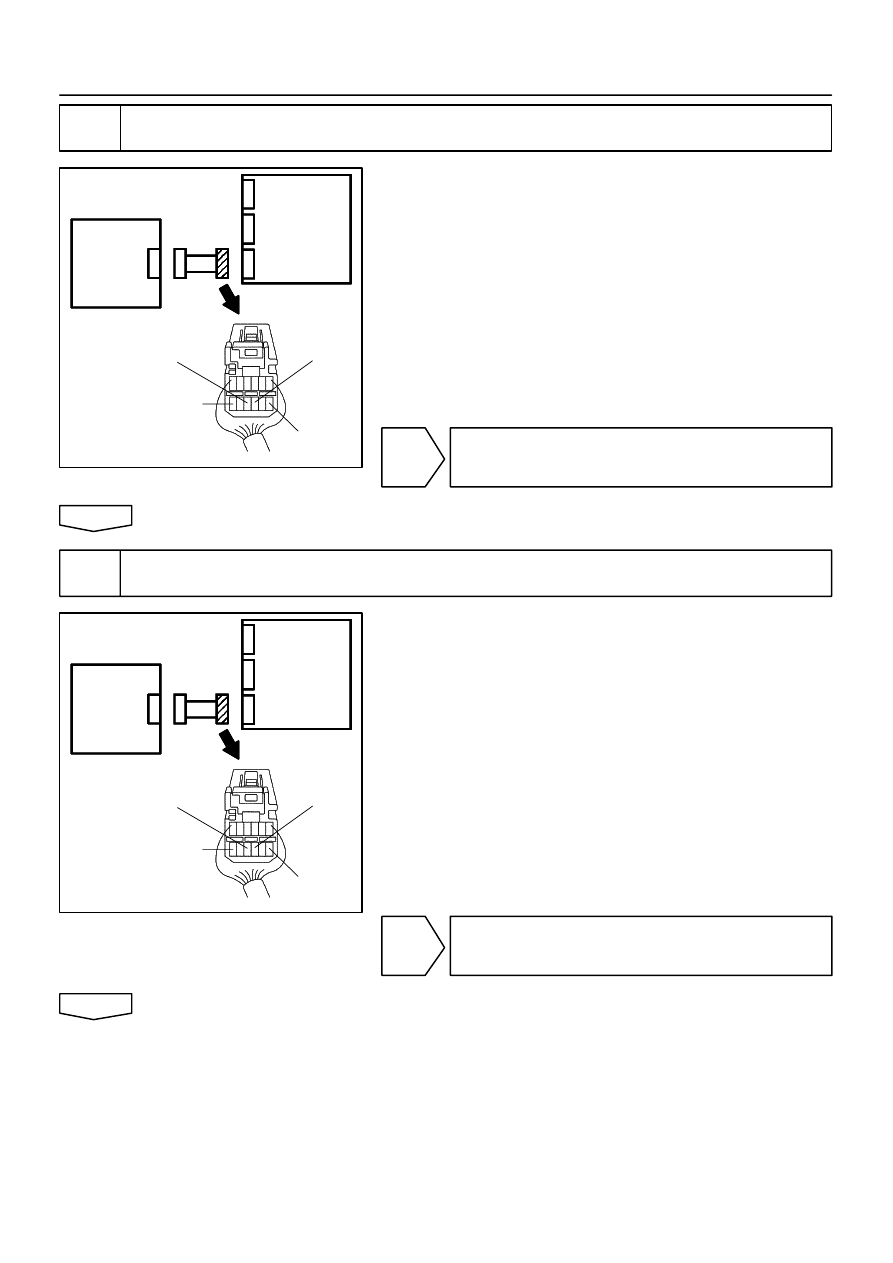
H01015
C82942
H01015
C82942
H40444
VUPR
Side
Airbag
Sensor
Assy RH
Airbag
Sensor
Assy
Center
SSR–
ESR
FSR
H01015
C82942
H01015
C82942
H40444
VUPR
Side
Airbag
Sensor
Assy RH
Airbag
Sensor
Assy
Center
SSR–
ESR
FSR
–
DIAGNOSTICS
SUPPLEMENTAL RESTRAINT SYSTEM (April, 2003)
05–527
692
Author:
Date:
2004 COROLLA (RM1037U)
6
CHECK SIDE AIRBAG SENSOR ASSY(RH) CIRCUIT(AIRBAG SENSOR ASSY
CENTER – SIDE AIRBAG SENSOR ASSY RH)
(a)
For the connector (on the airbag sensor assy center side)
between the airbag sensor assy center and the side air-
bag sensor assy (RH), measure the resistance between
VUPR and ESR, and between FSR and SSR–.
OK:
Resistance: 1M
Ω
or Higher
NG
REPAIR OR REPLACE INSTRUMENT PANEL
WIRE NO.3(AIRBAG SENSOR ASSY CENTER –
SIDE AIRBAG SENSOR ASSY RH)
OK
7
CHECK SIDE AIRBAG SENSOR ASSY(RH) CIRCUIT(TO B+)(AIRBAG SENSOR
ASSY CENTER – AIDE AIRBAG SENSOR ASSY RH)
(a)
Connect the negative (–) terminal cable to the battery,
and wait at least for 2 seconds.
(b)
Turn the ignition switch to ON.
(c)
For the connector (on the airbag sensor assy center side)
between the airbag sensor assy center and the side air-
bag sensor assy (RH), measure the voltage between
each terminal of VUPR, SSR– and FSR, and body
ground.
OK:
Voltage: Below 1 V
NG
REPAIR OR REPLACE INSTRUMENT PANEL
WIRE NO.3(AIRBAG SENSOR ASSY CENTER –
SIDE AIRBAG SENSOR ASSY RH)
OK
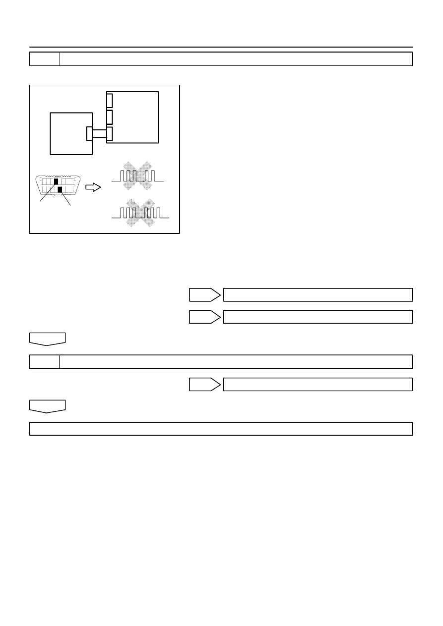
H10600 H01065
H01012
H01066
H41930
DLC3
CG
Tc
DTC B1140/32
Side
Airbag
Sensor
Assy LH
Airbag
Sensor
Assy
Center
DTC B1141/33
05–528
–
DIAGNOSTICS
SUPPLEMENTAL RESTRAINT SYSTEM (April, 2003)
693
Author:
Date:
2004 COROLLA (RM1037U)
8
CHECK SIDE AIR BAG SENSOR ASSY RH
SST
09843–18040
(a)
Turn the ignition switch to LOCK.
(b)
Disconnect the negative (–) terminal cable from the bat-
tery, and wait at least for 90 seconds.
(c)
Connect the airbag sensor assy center connector.
(d)
Interchange the side airbag sensor assy (RH) and LH and
connect the connectors to them.
(e)
Connect the negative (–) terminal cable to the battery,
and wait at least for 2 seconds.
(f)
Turn the ignition switch to ON, and wait at least for 20 se-
conds.
(g)
Clear the DTC stored in memory (See page
05–424
).
(h)
Turn the ignition switch to LOCK, and wait at least for 20
seconds.
(i)
Turn the ignition switch to ON, and wait at least for 20 se-
conds.
(j)
Check the DTC (See page
05–424
).
OK:
(A): DTC B1140/32 is not output.
(B): DTC B1141/33 is not output.
NG(A)
REPLACE AIR BAG SENSOR ASSY CENTER
NG(B)
REPLACE SIDE AIR BAG SENSOR ASSY RH
OK
9
USE SIMULATION METHOD TO CHECK
NG
Go to step 1
OK
REPLACE ALL SRS COMPONENTS INCLUDING THE WIRE HARNESS
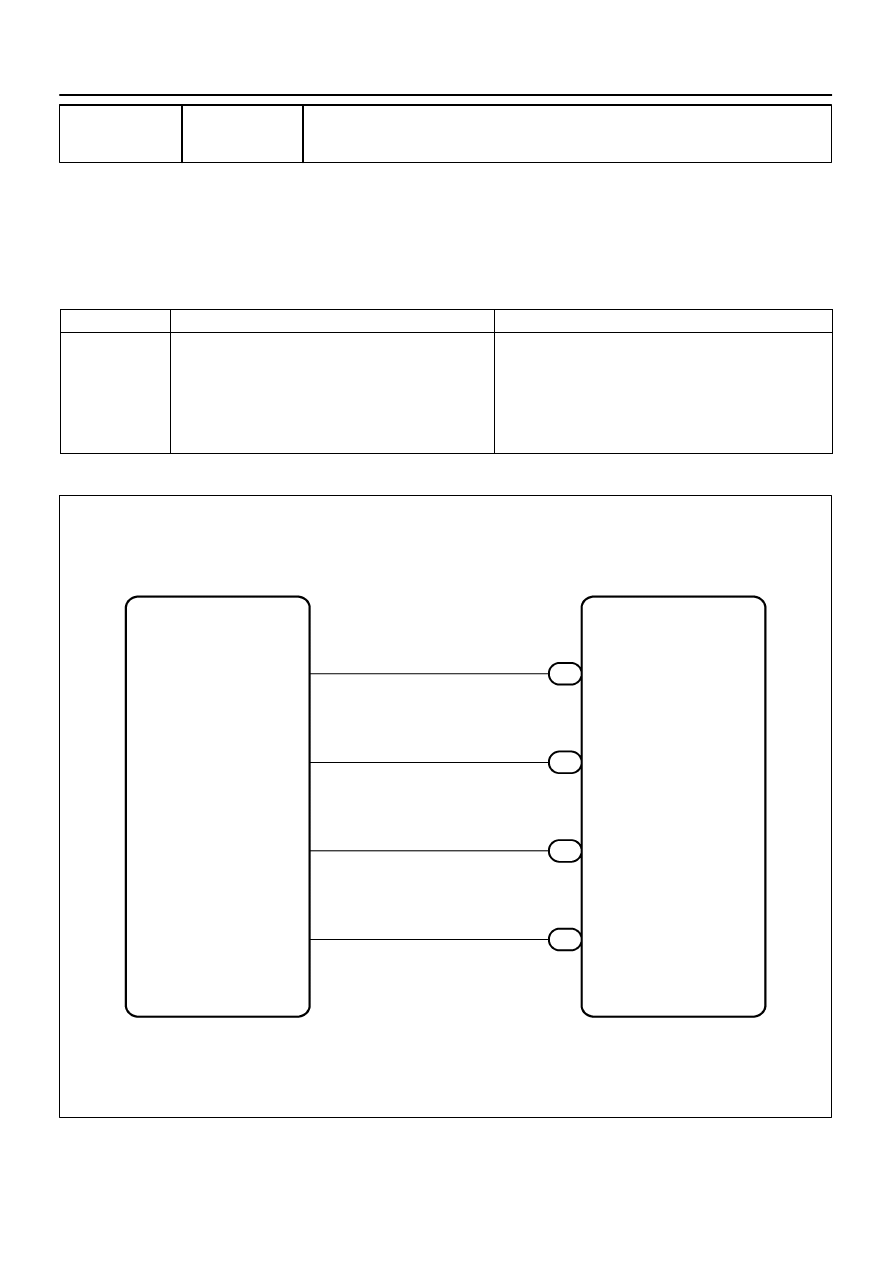
H01450
S10
Side Airbag Sensor Assy (LH)
Airbag Sensor Assy Center
LG–B
L–W
P–L
ESL
SSL–
FSL
VUPL
4
3
2
1
A12
12
9
10
7
GR–L
ESL
SSL–
FSL
VUPL
A12
A12
A12
–
DIAGNOSTICS
SUPPLEMENTAL RESTRAINT SYSTEM (April, 2003)
05–529
694
Author:
Date:
2004 COROLLA (RM1037U)
DTC
B1141/33 SIDE AIRBAG SENSOR ASSY (LH)
MALFUNCTION
CIRCUIT DESCRIPTION
The side airbag sensor assy (LH) circuit consists of the diagnosis circuit and lateral deceleration sensor, etc.
It receives signals from the lateral deceleration sensor, judges whether or not the SRS must be activated,
and detects diagnosis system malfunction.
DTC B1141/33 is recorded when occurrence of a malfunction in the side airbag sensor assy (LH) is detected.
DTC No.
DTC Detecting Condition
Trouble Area
B1141/33
Short circuit in wire harness of side airbag sensor LH
(to ground)
Short circuit in wire harness of side airbag sensor LH
(to B+)
Open circuit in wire harness of side airbag sensor LH
Side airbag sensor assy LH malfunction
Airbag sensor assy center malfunction
Side airbag sensor assy (LH)
Airbag sensor assy center
Instrument panel wire No.3
WIRING DIAGRAM
055Z7–05
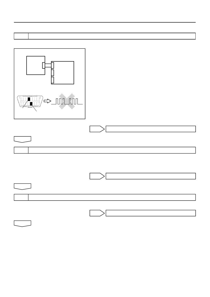
H01007
H10600 H01066
H40445
Side
Airbag
Sensor
Assy LH
Airbag
Sensor
Assy
Center
DLC3
CG
Tc
DTC B1141/33
05–530
–
DIAGNOSTICS
SUPPLEMENTAL RESTRAINT SYSTEM (April, 2003)
695
Author:
Date:
2004 COROLLA (RM1037U)
INSPECTION PROCEDURE
1
CHECK SIDE AIR BAG SENSOR ASSY LH
SST
09843–18040
(a)
Connect the negative (–) terminal cable to the battery,
and wait at least for 2 seconds.
(b)
Turn the ignition switch to ON, and wait at least for 20 se-
conds.
(c)
Clear the DTC stored in memory (See page
05–424
).
(d)
Turn the ignition switch to LOCK, and wait at least for 20
seconds.
(e)
Turn the ignition switch to ON, and wait at least for 20 se-
conds.
(f)
Check the DTC (See page
05–424
).
OK:
DTC B1141/33 is not output.
OK
USE SIMULATION METHOD TO CHECK
NG
2
CHECK AIRBAG SENSOR ASSY CENTER CONNECTOR
(a)
Turn the ignition switch to LOCK.
(b)
Disconnect the negative (–) terminal cable from the battery, and wait at least for 90 seconds.
(c)
Check that the connectors is properly connected to the airbag sensor assy center.
NG
CONNECT CONNECTORS
OK
3
CHECK SIDE AIRBAG SENSOR ASSY CONNECTOR
(a)
Check that the connector is properly connected to the side airbag sensor assy (LH).
NG
CONNECT CONNECTORS
OK
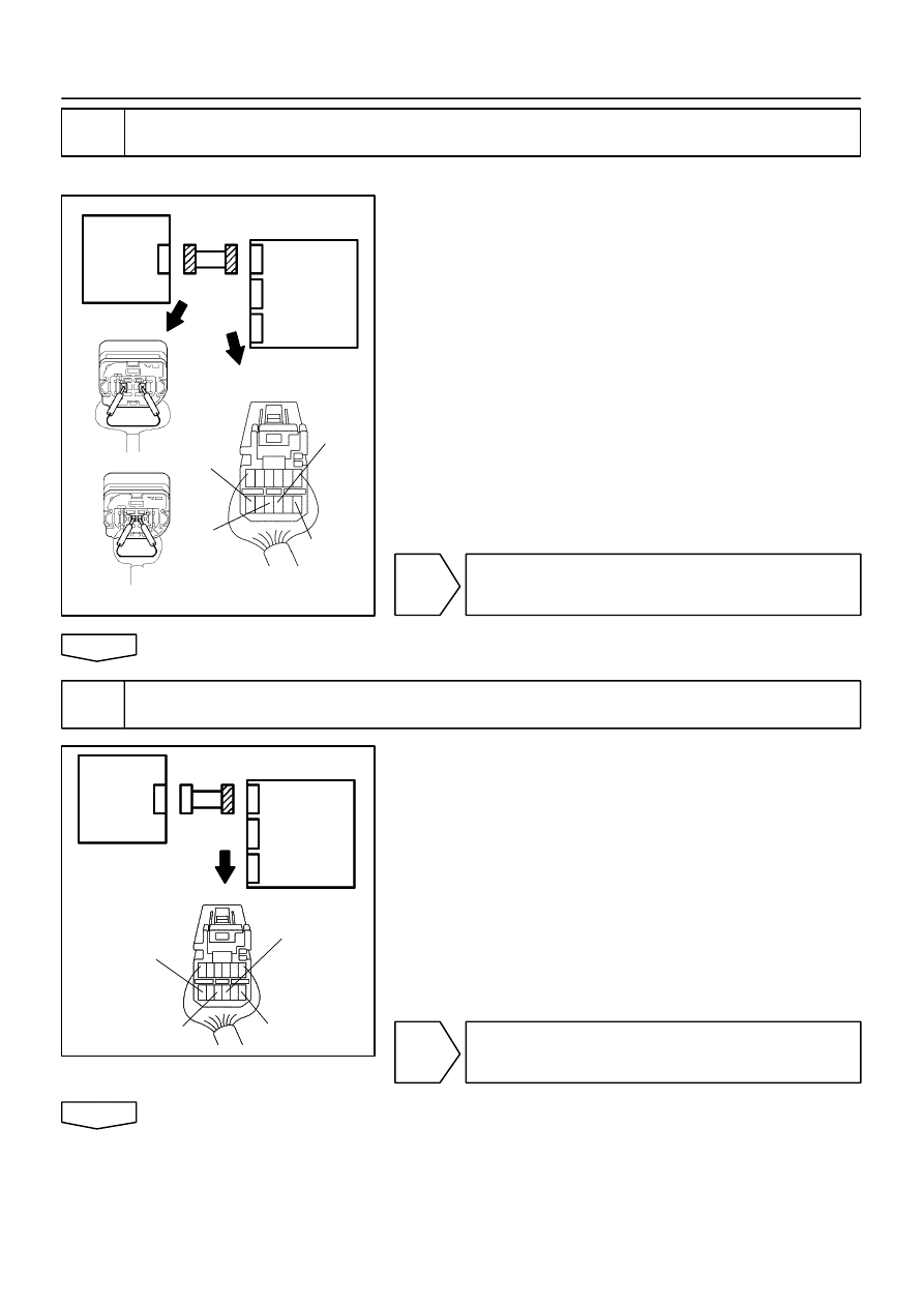
H01010
C81676
C91384
C91385
H41636
ESL
FSL
VUPL
Side
Airbag
Sensor
Assy LH
Airbag
Sensor
Assy
Center
SSL–
H01010
C81676
H01010
C81676
H40447
VUPL
Side
Airbag
Sensor
Assy LH
Airbag
Sensor
Assy
Center
ESL
FSL
SSL–
–
DIAGNOSTICS
SUPPLEMENTAL RESTRAINT SYSTEM (April, 2003)
05–531
696
Author:
Date:
2004 COROLLA (RM1037U)
4
CHECK SIDE AIRBAG SENSOR ASSY(LH) CIRCUIT(OPEN)(AIRBAG SENSOR
ASSY CENTER – SIDE AIRBAG SENSOR ASSY LH)
SST
09843–18040
(a)
Disconnect the connectors between the airbag sensor
assy center and the side airbag sensor assy LH.
(b)
Using a service wire, connect VUPL and ESL, and FSL
and SSL– of the connector (on the side airbag sensor
assy side) between the airbag sensor assy center and the
side airbag sensor assy (LH).
(c)
For the connector (on the airbag sensor assy center side)
between the airbag sensor assy center and the side air-
bag sensor assy (LH), measure the resistance between
VUPL and ESL, and between FSL and SSL–.
OK:
Resistance: Below 1
Ω
NG
REPAIR OR REPLACE INSTRUMENT PANEL
WIRE NO.3(AIRBAG SENSOR ASSY CENTER –
SIDE AIRBAG SENSOR ASSY LH)
OK
5
CHECK SIDE AIRBAG SENSOR ASSY(LH) CIRCUIT(TO GROUND)(AIRBAG
SENSOR ASSY CENTER – SIDE AIRBAG SENSOR ASSY LH)
(a)
Disconnect the connection between VUPL and ESL, and
between FSL and SSL–.
(b)
For the connector (on the airbag sensor assy center side)
between the airbag sensor assy center and the side air-
bag sensor assy (LH), measure the resistance between
each terminal of VUPL, SSL– and FSL, and body ground.
OK:
Resistance: 1M
Ω
or Higher
NG
REPAIR OR REPLACE INSTRUMENT PANEL
WIRE NO.3(AIRBAG SENSOR ASSY CENTER –
SIDE AIRBAG SENSOR ASSY LH)
OK
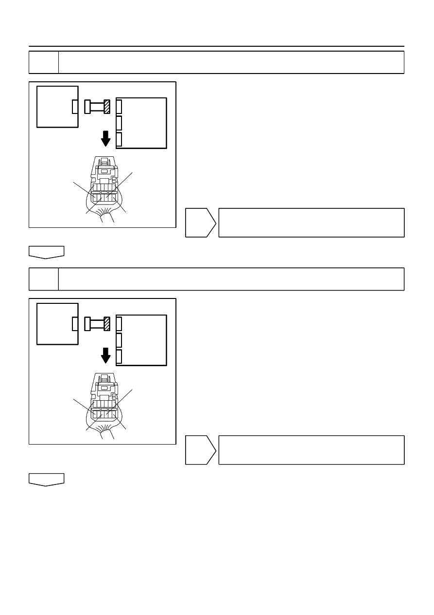
H01010
C81676
H01010
C81676
H40447
VUPL
Side
Airbag
Sensor
Assy LH
Airbag
Sensor
Assy
Center
ESL
FSL
SSL–
H01010
C81676
H01010
C81676
H40447
VUPL
Side
Airbag
Sensor
Assy LH
Airbag
Sensor
Assy
Center
ESL
FSL
SSL–
05–532
–
DIAGNOSTICS
SUPPLEMENTAL RESTRAINT SYSTEM (April, 2003)
697
Author:
Date:
2004 COROLLA (RM1037U)
6
CHECK SIDE AIRBAG SENSOR ASSY(LH) CIRCUIT(AIRBAG SENSOR ASSY
CENTER – SIDE AIRBAG SENSOR ASSY LH)
(a)
For the connector (on the airbag sensor assy center side)
between the airbag sensor assy center and the side air-
bag sensor assy (LH), measure the resistance between
VUPL and ESL, and between FSL and SSL–.
OK:
Resistance: 1M
Ω
or Higher
NG
REPAIR OR REPLACE INSTRUMENT PANEL
WIRE NO.3(AIRBAG SENSOR ASSY CENTER –
SIDE AIRBAG SENSOR ASSY LH)
OK
7
CHECK SIDE AIRBAG SENSOR ASSY(LH) CIRCUIT(TO B+)(AIRBAG SENSOR
ASSY CENTER – SIDE AIRBAG SENSOR ASSY LH)
(a)
Connect the negative (–) terminal cable to the battery,
and wait at least for 2 seconds.
(b)
Turn the ignition switch to ON.
(c)
For the connector (on the airbag sensor assy center side)
between the airbag sensor assy center and the side air-
bag sensor assy (LH), measure the voltage between
each terminal of VUPL, SSL– and FSL, and body ground.
OK:
Voltage: Below 1V
NG
REPAIR OR REPLACE INSTRUMENT PANEL
WIRE NO.3(AIRBAG SENSOR ASSY CENTER –
SIDE AIRBAG SENSOR ASSY LH)
OK
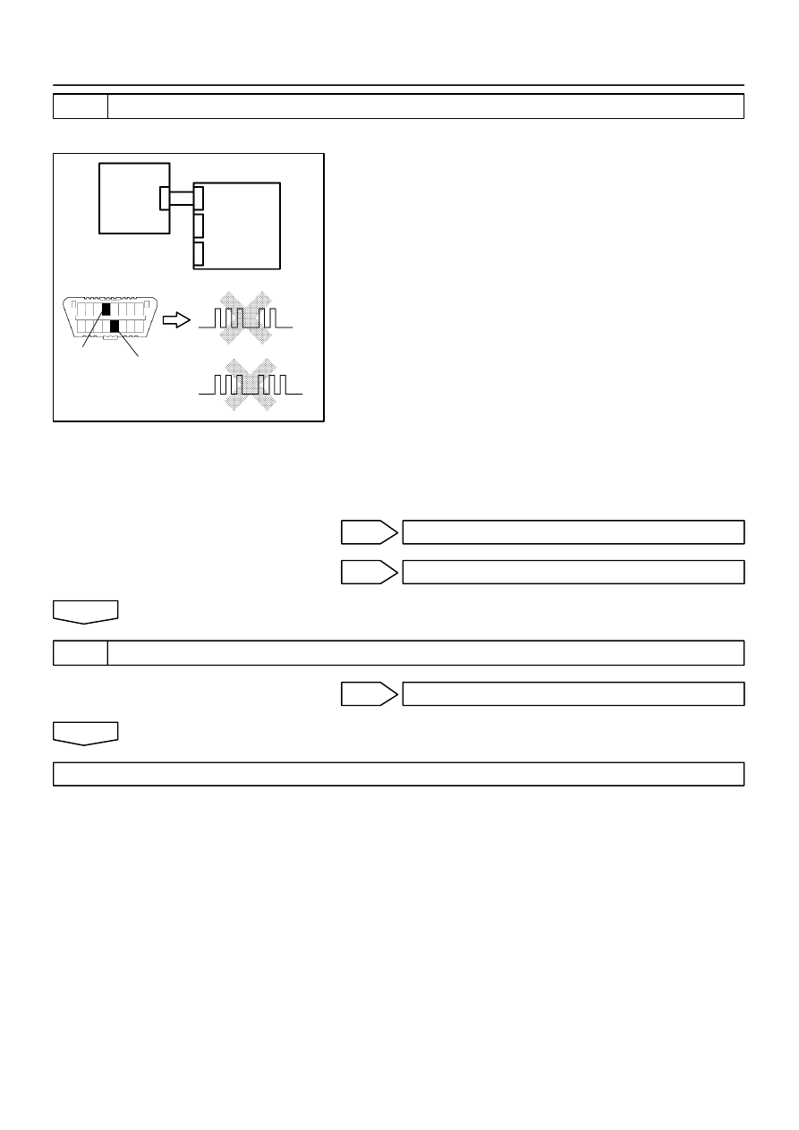
H01007
H10600 H01065
H01066
H41931
DLC3
CG
Tc
DTC B1141/33
Airbag
Sensor
Assy
Center
Side
Airbag
Sensor
Assy RH
DTC B1140/32
–
DIAGNOSTICS
SUPPLEMENTAL RESTRAINT SYSTEM (April, 2003)
05–533
698
Author:
Date:
2004 COROLLA (RM1037U)
8
CHECK SIDE AIR BAG SENSOR ASSY LH
SST
09843–18040
(a)
Turn the ignition switch to LOCK.
(b)
Disconnect the negative (–) terminal cable from the bat-
tery, and wait at least for 90 seconds.
(c)
Connect the airbag sensor assy center connector.
(d)
Interchange the side airbag sensor assy (LH) and RH and
connect the connectors to them.
(e)
Connect the negative (–) terminal cable to the battery,
and wait at least for 2 seconds.
(f)
Turn the ignition switch to ON, and wait at least for 20 se-
conds.
(g)
Clear the DTC stored in memory (See page
05–424
).
(h)
Turn the ignition switch to LOCK, and wait at least for 20
seconds.
(i)
Turn the ignition switch to ON, and wait at least for 20 se-
conds.
(j)
Check the DTC (See page
05–424
).
OK:
(A): DTC B1140/32 is not output.
(B): DTC B1141/33 is not output.
NG(A)
REPLACE SIDE AIR BAG SENSOR ASSY LH
NG(B)
REPLACE AIR BAG SENSOR ASSY CENTER
OK
9
USE SIMULATION METHOD TO CHECK
NG
Go to step 1
OK
REPLACE ALL SRS COMPONENTS INCLUDING THE WIRE HARNESS
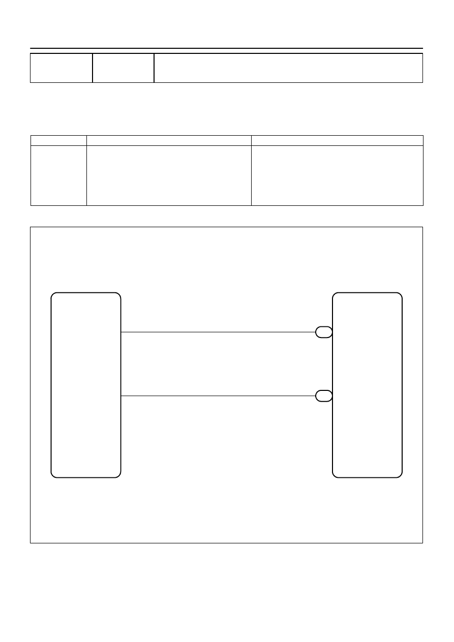
H42003
Airbag Sensor Assy Center
A12
LSP+
LSP–
A12
B6
Seat Position Airbag Sensor
3
4
G–W
R–B
4
5
05–534
–
DIAGNOSTICS
SUPPLEMENTAL RESTRAINT SYSTEM (April, 2003)
699
Author:
Date:
2004 COROLLA (RM1037U)
DTC
B1153/25 SEAT POSITION AIRBAG SENSOR
MALFUNCTION
CIRCUIT DESCRIPTION
The seat position sensor circuit consists of the airbag sensor assy center and seat position sensor.
DTC B1153/25 is recorded when a malfunction is detected in the seat position sensor circuit.
DTC No.
DTC Detecting Condition
Trouble Area
B1153/25
Short circuit between LSP+ wire harness and LSP– wire
harness (to B+)
Short circuit between LSP+ wire harness and LSP– wire
harness (to ground)
Open circuit in LSP+ wire harness or LSP– wire harness
Seat position airbag sensor malfunction
Airbag sensor assy center malfunction
Seat position airbag sensor
Airbag sensor assy center
Wire harness (Seat position airbag sensor – Front seat inner
belt assy)
Instrument panel wire No.3
WIRING DIAGRAM
055ZA–04
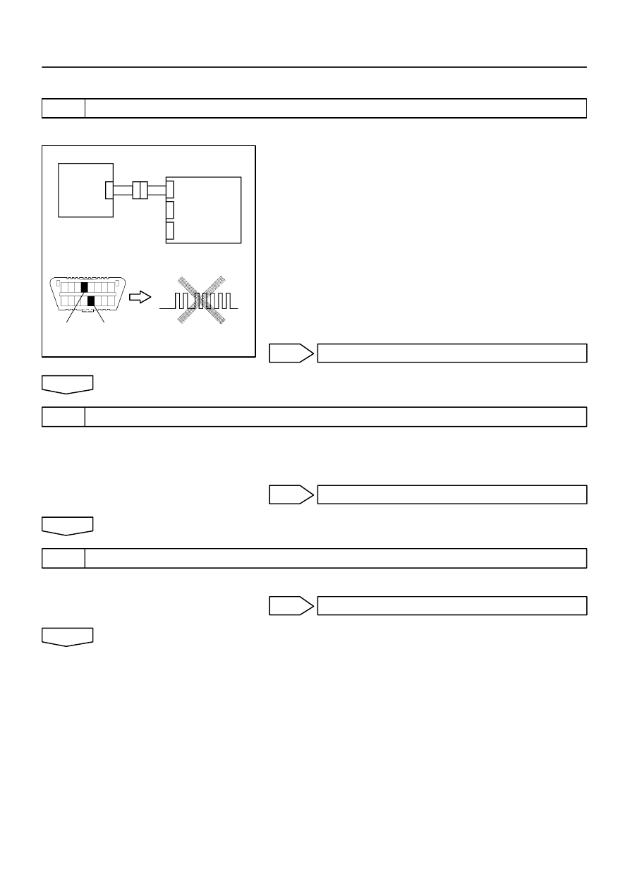
H02757
H10600 C91522
H41990
Seat
Position
Airbag
Sensor
Airbag
Sensor
Assy
Center
DLC3
CG
Tc
DTC B1153/25
–
DIAGNOSTICS
SUPPLEMENTAL RESTRAINT SYSTEM (April, 2003)
05–535
700
Author:
Date:
2004 COROLLA (RM1037U)
INSPECTION PROCEDURE
1
CHECK SEAT POSITION AIR BAG SENSOR
SST
09843–18040
(a)
Turn the ignition switch to ON, and wait at least for 20 se-
conds.
(b)
Clear the DTC stored in memory (See page
05–424
).
(c)
Turn the ignition switch to LOCK, and wait at least for 20
seconds.
(d)
Turn the ignition switch to ON, and wait at least for 20 se-
conds.
(e)
Check the DTC (See page
05–424
).
OK:
DTC B1153/25 is not output.
HINT:
Codes other than code B1153/25 may be output at this time, but
they are not relevant to this check.
OK
USE SIMULATION METHOD TO CHECK
NG
2
CHECK AIRBAG SENSOR ASSY CENTER CONNECTOR
(a)
Turn the ignition switch to LOCK.
(b)
Disconnect the negative (–) terminal cable from the battery, and wait at least for 90 seconds.
(c)
Check that the connector is properly connected to the airbag sensor assy center.
NG
CONNECT CONNECTORS
OK
3
CHECK SEAT POSITION AIRBAG SENSOR CONNECTOR
(a)
Check that the connector is properly connected to the seat position airbag sensor.
NG
CONNECT CONNECTORS
OK
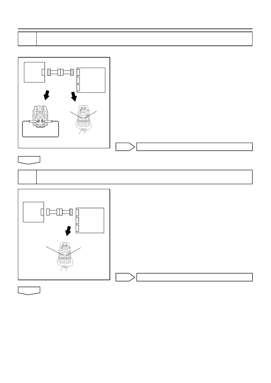
H03353
C91524 C91525
H41988
Airbag
Sensor
Assy
Center
LSP+
LSP–
Seat
Position
Airbag
Sensor
H03355
C91525
H41989
Airbag
Sensor
Assy
Center
LSP+
LSP–
Seat
Position
Airbag
Sensor
05–536
–
DIAGNOSTICS
SUPPLEMENTAL RESTRAINT SYSTEM (April, 2003)
701
Author:
Date:
2004 COROLLA (RM1037U)
4
CHECK SEAT POSITION AIRBAG SENSOR CIRCUIT (OPEN)(AIRBAG SENSOR
ASSY CENTER – SEAT POSITION AIRBAG SENSOR)
SST
09843–18040
(a)
Disconnect the connectors between the airbag sensor
assy center and the seat position airbag sensor.
(b)
Using a service wire, connect LSP+ and LSP– of the con-
nector (on the seat position airbag sensor side) between
the airbag sensor assy center and the seat position airbag
sensor.
(c)
For the connector (on the airbag sensor assy center side)
between the airbag sensor assy center and the seat posi-
tion airbag sensor, measure the resistance between
LSP+ and LSP–.
OK:
Resistance: Below 1
Ω
NG
Go to step 10
OK
5
CHECK SEAT POSITION AIRBAG SENSOR CIRCUIT (TO GROUND)(AIRBAG
SENSOR ASSY CENTER – SEAT POSITION AIRBAG SENSOR)
(a)
Release the service wire of the connector (on the seat
position airbag sensor side) between the seat position air-
bag sensor and the airbag sensor assy center.
(b)
For the connector (on the airbag sensor assy center side)
between the airbag sensor assy center and the seat posi-
tion airbag sensor, measure the resistance between body
ground and each of LSP+ and LSP–.
OK:
Resistance: 1 M
Ω
or Higher
NG
Go to step 11
OK
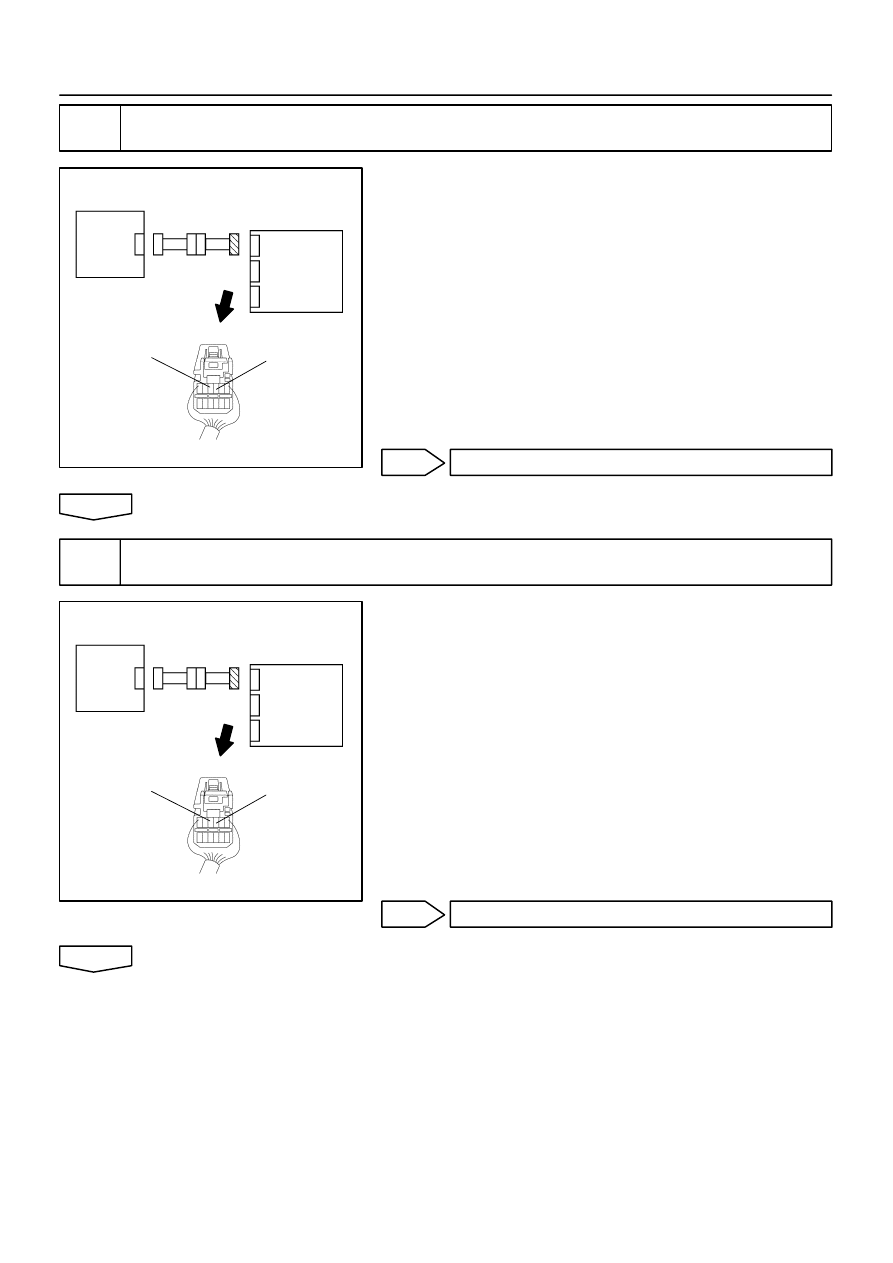
H03355
C91525
H41989
Airbag
Sensor
Assy
Center
LSP+
LSP–
Seat
Position
Airbag
Sensor
H03355
C91525
H41989
Airbag
Sensor
Assy
Center
LSP+
LSP–
Seat
Position
Airbag
Sensor
–
DIAGNOSTICS
SUPPLEMENTAL RESTRAINT SYSTEM (April, 2003)
05–537
702
Author:
Date:
2004 COROLLA (RM1037U)
6
CHECK SEAT POSITION AIRBAG SENSOR CIRCUIT(AIRBAG SENSOR ASSY
CENTER – SEAT POSITION AIRBAG SENSOR)
(a)
For the connector (on the airbag sensor assy center side)
between the airbag sensor assy center and the seat posi-
tion airbag sensor, measure the resistance between
LSP+ and LSP–.
OK:
Resistance: 1 M
Ω
or Higher
NG
Go to step 12
OK
7
CHECK SEAT POSITION AIRBAG SENSOR CIRCUIT (TO B+)(AIRBAG SENSOR
ASSY CENTER – SEAT POSITION AIRBAG SENSOR)
(a)
Connect the negative (–) terminal cable to the battery,
and wait at least for 2 seconds.
(b)
Turn the ignition switch to ON.
(c)
For the connector (on the airbag sensor assy center side)
between the airbag sensor assy center and the seat posi-
tion airbag sensor, measure the voltage between the
body ground and each of LSP+ and LSP–.
OK:
Voltage: Below 1 V
NG
Go to step 13
OK
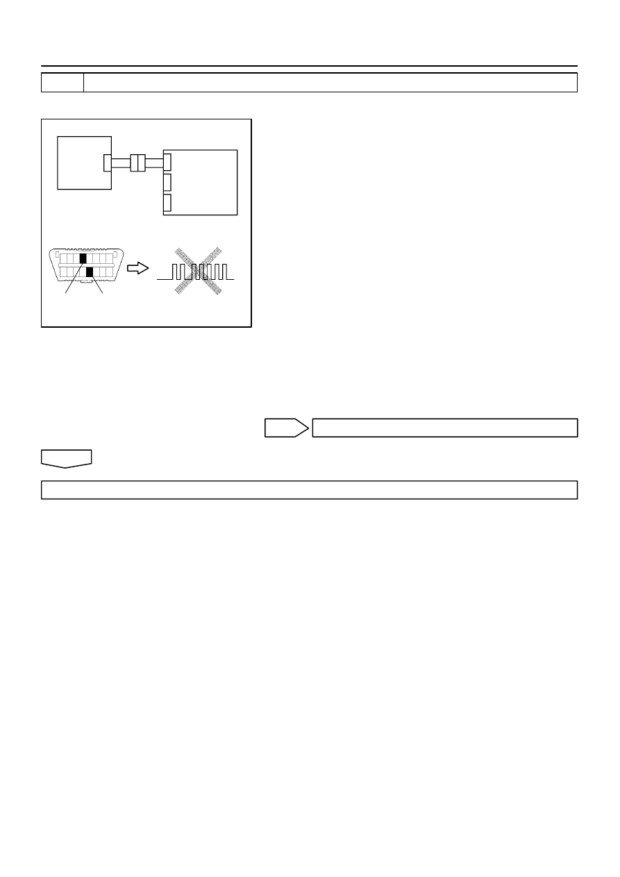
H02757
H10600 C91522
H41990
Airbag
Sensor
Assy
Center
DLC3
CG
Tc
DTC B1153/25
Seat
Position
Airbag
Sensor
05–538
–
DIAGNOSTICS
SUPPLEMENTAL RESTRAINT SYSTEM (April, 2003)
703
Author:
Date:
2004 COROLLA (RM1037U)
8
CHECK SEAT POSITION AIR BAG SENSOR
SST
09843–18040
(a)
Turn the ignition switch to LOCK.
(b)
Disconnect the negative (–) terminal cable from the bat-
tery, and wait at least for 90 seconds.
(c)
Connect the connectors of the seat position airbag sensor
and the airbag sensor assy center.
(d)
Connect the negative (–) terminal cable to the battery,
and wait at least for 2 seconds.
(e)
Turn the ignition switch to ON, and wait at least for 20 se-
conds.
(f)
Clear the DTC stored in memory (See page
05–424
).
(g)
Turn the ignition switch to LOCK, and wait at least for 20
seconds.
(h)
Turn the ignition switch to ON, and wait at least for 20 se-
conds.
(i)
Check the DTC (See page
05–424
).
OK:
DTC D1153/25 is not output.
HINT:
Codes other that code B1153/25 may be output at this time, but
they are not relevant to this check.
NG
REPLACE SEAT POSITION AIR BAG SENSOR
OK
USE SIMULATION METHOD TO CHECK

H02757
H10600 C91522
H41990
Airbag
Sensor
Assy
Center
DLC3
CG
Tc
DTC B1153/25
Seat
Position
Airbag
Sensor
–
DIAGNOSTICS
SUPPLEMENTAL RESTRAINT SYSTEM (April, 2003)
05–539
704
Author:
Date:
2004 COROLLA (RM1037U)
9
CHECK AIR BAG SENSOR ASSY CENTER
SST
09843–18040
(a)
Turn the ignition switch to LOCK.
(b)
Disconnect the negative (–) terminal cable from the bat-
tery, and wait at least for 90 seconds.
(c)
Connect the connector of a new seat position airbag sen-
sor.
(d)
Connect the negative (–) terminal cable to the battery,
and wait at least for 2 seconds.
(e)
Turn the ignition switch to ON, and wait at least for 20 se-
conds.
(f)
Clear the DTC stored in memory (See page
05–424
).
(g)
Turn the ignition switch to LOCK, and wait at least for 20
seconds.
(h)
Turn the ignition switch to ON, and wait at least for 20 se-
conds.
(i)
Check the DTC (See page
05–424
).
OK:
DTC D1153/25 is not output.
HINT:
Codes other that code B1153/25 may be output at this time, but
they are not relevant to this check.
NG
REPLACE AIR BAG SENSOR ASSY CENTER
OK
USE SIMULATION METHOD TO CHECK
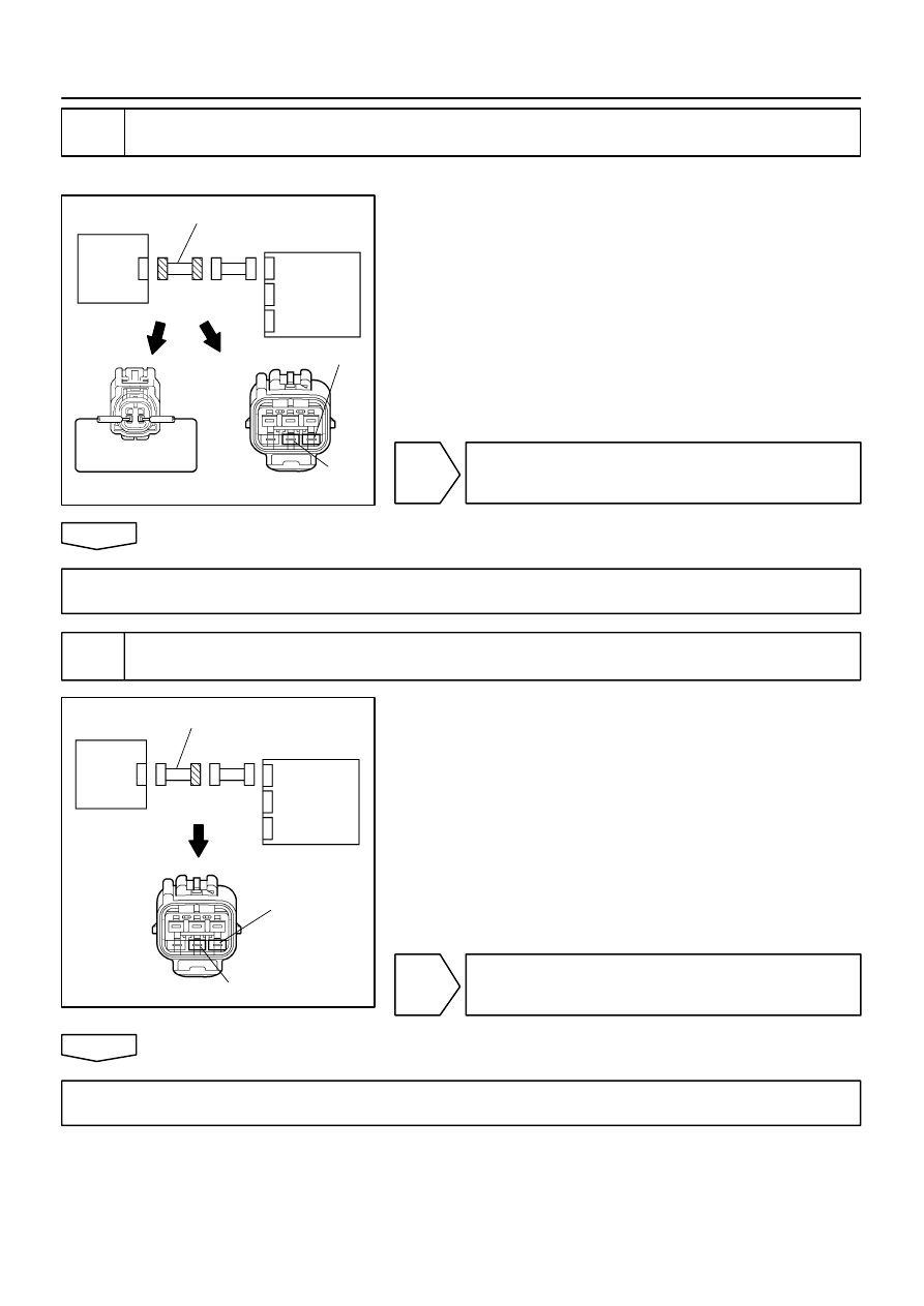
H03352
C91524 C91530
H42101
Airbag
Sensor
Assy
Center
LSP+
LSP–
Seat
Position
Airbag
Sensor
Front Seat Wire
C91530
H03354
H42102
Airbag
Sensor
Assy
Center
LSP+
LSP–
Seat
Position
Airbag
Sensor
Front Seat Wire
05–540
–
DIAGNOSTICS
SUPPLEMENTAL RESTRAINT SYSTEM (April, 2003)
705
Author:
Date:
2004 COROLLA (RM1037U)
10
CHECK WIRE HARNESS(SEAT POSITION AIRBAG SENSOR – FRONT SEAT
INNER BELT ASSY)
SST
09843–18040
(a)
Disconnect the front seat wire connector on the airbag
sensor assy center side.
(b)
For the front seat wire connector (on the airbag sensor
assy center side) between the airbag sensor assy center
and the seat position airbag sensor, measure the resis-
tance between LSP+ and LSP–.
OK:
Resistance: Below 1
Ω
NG
REPAIR OR REPLACE WIRE HARNESS(SEAT
POSITION SENSOR – FRONT SEAT INNER
BELT ASSY)
OK
REPAIR OR REPLACE INSTRUMENT PANEL WIRE NO.3(AIRBAG SENSOR ASSY CENTER –
FRONT SEAT INNER BELT ASSY)
11
CHECK WIRE HARNESS(SEAT POSITION AIRBAG SENSOR – FRONT SEAT
INNER BELT ASSY)
(a)
Disconnect the front seat wire connector on the airbag
sensor assy center side.
(b)
For the front seat wire connector (on the airbag sensor
assy center side) between the airbag sensor assy center
and the seat position sensor, measure the resistance be-
tween body ground and each of LSP+ and LSP–.
OK:
Resistance: 1 M
Ω
or Higher
NG
REPAIR OR REPLACE WIRE HARNESS(SEAT
POSITION SENSOR – FRONT SEAT INNER
BELT ASSY)
OK
REPAIR OR REPLACE INSTRUMENT PANEL WIRE NO.3(AIRBAG SENSOR ASSY CENTER –
FRONT SEAT INNER BELT ASSY)
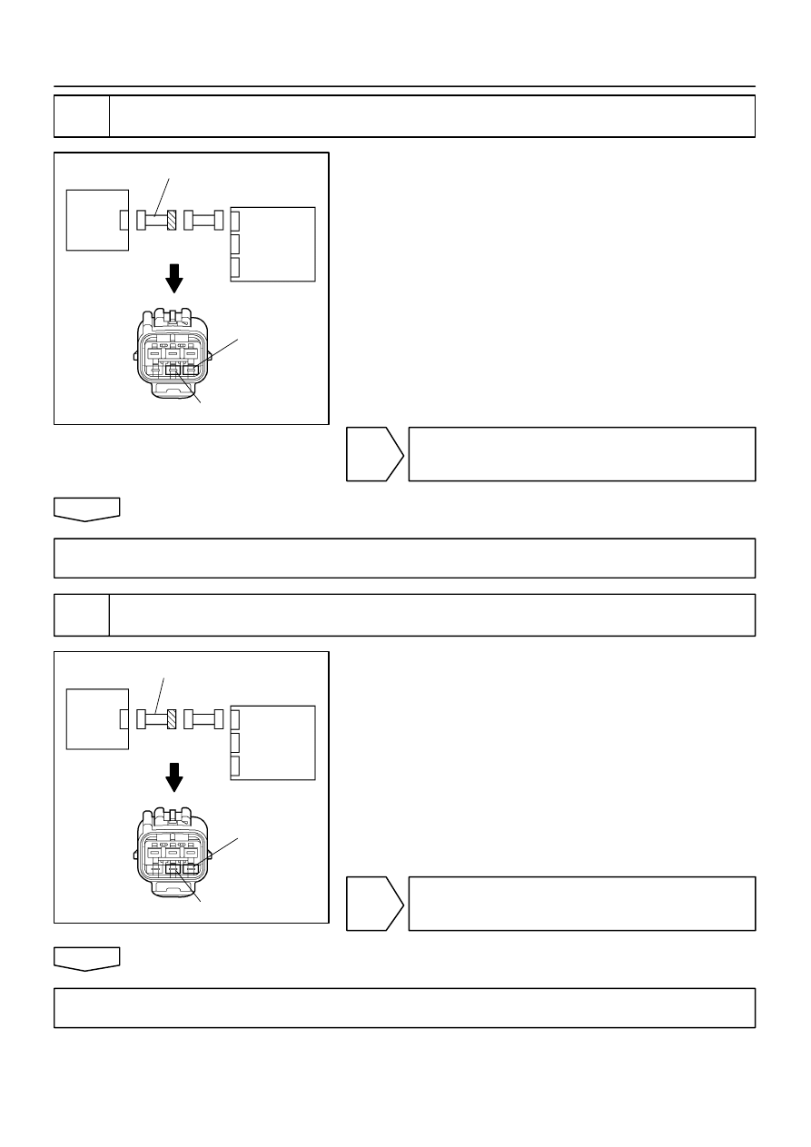
C91530
H03354
H42102
Airbag
Sensor
Assy
Center
LSP+
LSP–
Seat
Position
Airbag
Sensor
Front Seat Wire
C91530
H03354
H42102
Seat
Position
Sensor
Airbag
Sensor
Assy
Center
LSP+
LSP–
Front Seat Wire
–
DIAGNOSTICS
SUPPLEMENTAL RESTRAINT SYSTEM (April, 2003)
05–541
706
Author:
Date:
2004 COROLLA (RM1037U)
12
CHECK WIRE HARNESS(SEAT POSITION AIRBAG SENSOR – FRONT SEAT
INNER BELT ASSY)
(a)
Disconnect the negative (–) terminal cable from the bat-
tery, and wait at least for 90 seconds.
(b)
Disconnect the front seat wire connector on the airbag
sensor assy center side.
(c)
Connect the negative (–) terminal cable to the battery,
and wait at least for 2 seconds.
(d)
Turn the ignition switch to ON, and wait at least for 60 se-
conds.
(e)
For the front seat wire connector (on the airbag sensor
assy center side) between the front seat inner belt assy
and the seat position airbag sensor, measure the voltage
between body ground and each of LSP+ and LSP–.
OK:
Voltage: Below 1 V
NG
REPAIR OR REPLACE WIRE HARNESS(SEAT
POSITION AIRBAG SENSOR – FRONT SEAT IN-
NER BELT ASSY)
OK
REPAIR OR REPLACE INSTRUMENT PANEL WIRE NO.3(AIRBAG SENSOR ASSY CENTER –
FRONT SEAT INNER BELT ASSY)
13
CHECK WIRE HARNESS(SEAT POSITION AIRBAG SENSOR – FRONT SEAT
INNER BELT ASSY)
(a)
Turn the ignition switch to LOCK.
(b)
For the front seat wire connector (on the airbag sensor
assy center side) between the airbag sensor assy center
and the seat position sensor, measure the resistance be-
tween LSP+ and LSP–.
OK:
Resistance: 1 M
Ω
or Higher
NG
REPAIR OR REPLACE WIRE HARNESS(SEAT
POSITION AIRBAG SENSOR – FRONT SEAT IN-
NER BELT ASSY)
OK
REPAIR OR REPLACE INSTRUMENT PANEL WIRE NO.3(AIRBAG SENSOR ASSY CENTER –
FRONT SEAT INNER BELT ASSY)

H02750
9
A13 +SR
IA1
B–W
–SR
A13
20
1
2
B–W
BR–W
BR–W
2
1
+SR
–SR
Airbag Sensor Assy Center
A6
Airbag Front RH Sensor
IA1
05–542
–
DIAGNOSTICS
SUPPLEMENTAL RESTRAINT SYSTEM (April, 2003)
707
Author:
Date:
2004 COROLLA (RM1037U)
DTC
B1156/15 FRONT AIRBAG SENSOR (RH)
MALFUNCTION
DTC
B1157/15 FRONT AIRBAG SENSOR (RH)
MALFUNCTION
CIRCUIT DESCRIPTION
The airbag front RH sensor circuit consists of the airbag sensor assy center and airbag front RH sensor.
DTC B1156/B1157/15 is recorded when a malfunction is detected in the airbag front RH sensor circuit.
DTC No.
DTC Detecting Condition
Trouble Area
B1156/B1157/15
Airbag front RH sensor malfunction
Airbag front RH sensor
Airbag sensor assy center
Instrument panel wire
Engine room main wire
WIRING DIAGRAM
057US–02
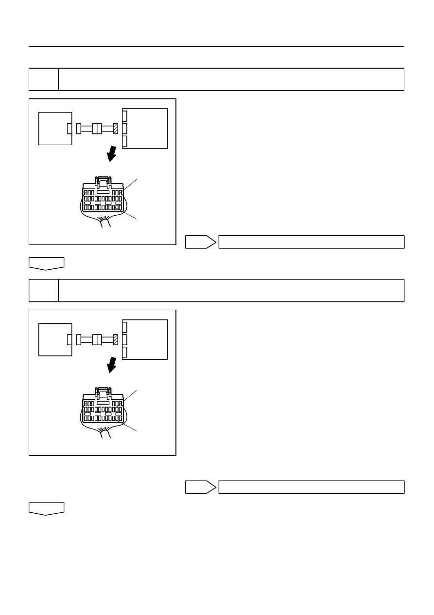
H03355
C81408
H03355
C81408
H40069
Airbag
Sensor
Assy
Center
+SR
–SR
Airbag
Front RH
Sensor
H03355
C81408
H03355
C81408
H40069
+SR
–SR
Airbag
Sensor
Assy
Center
Airbag
Front RH
Sensor
–
DIAGNOSTICS
SUPPLEMENTAL RESTRAINT SYSTEM (April, 2003)
05–543
708
Author:
Date:
2004 COROLLA (RM1037U)
INSPECTION PROCEDURE
1
CHECK FRONT AIRBAG SENSOR (RH) CIRCUIT (TO B+)(AIRBAG SENSOR ASSY
CENTER – AIRBAG FRONT RH SENSOR)
(a)
Disconnect the negative (–) terminal cable from the bat-
tery, and wait at least for 90 seconds.
(b)
Disconnect the connectors between the airbag front RH
sensor and the airbag sensor assy center.
(c)
Connect the negative (–) terminal cable to the battery,
and wait at least for 2 seconds.
(d)
Turn the ignition switch to ON.
(e)
For the connector (on the airbag sensor assy center side)
between the airbag front RH sensor and the airbag sen-
sor assy center, measure the voltage between body
ground and each of +SR and –SR.
OK:
Voltage: Below 1 V
NG
Go to step 6
OK
2
CHECK FRONT AIRBAG SENSOR (RH) CIRCUIT (TO GROUND)(AIRBAG SENSOR
ASSY – AIRBAG FRONT RH SENSOR)
(a)
Turn the ignition switch to LOCK.
(b)
Disconnect the negative (–) terminal cable from the bat-
tery, and wait at least for 90 seconds.
(c)
For the connector (on the airbag sensor assy center side)
between the airbag front RH sensor and the airbag sen-
sor assy center, measure the resistance between body
ground and each of +SR and –SR.
OK:
Resistance: 1 M
Ω
or Higher
NG
Go to step 7
OK
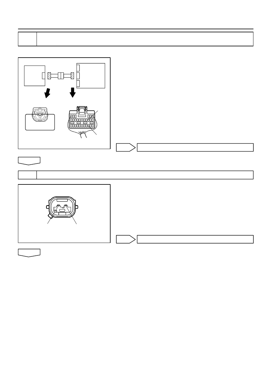
H03353
C81408
H08016
H41800
+SR
–SR
Airbag
Sensor
Assy
Center
Airbag
Front RH
Sensor
C54743
C54743
H40071
+SR
–SR
05–544
–
DIAGNOSTICS
SUPPLEMENTAL RESTRAINT SYSTEM (April, 2003)
709
Author:
Date:
2004 COROLLA (RM1037U)
3
CHECK FRONT AIRBAG SENSOR (RH) CIRCUIT(OPEN)(AIRBAG SENSOR ASSY
CENTER – AIRBAG FRONT RH SENSOR)
SST
09843–18040
(a)
Using a service wire, connect +SR and –SR of the con-
nector (on the airbag front RH sensor side) between the
airbag front RH sensor and the airbag sensor assy center.
(b)
For the connector (on the airbag sensor assy center side)
between the airbag front RH sensor and the airbag sen-
sor assy center, measure the resistance between +SR
and –SR.
OK:
Resistance: Below 1
Ω
NG
Go to step 8
OK
4
INSPECT AIR BAG FRONT RH SENSOR
(a)
For the connector of the airbag front RH sensor, measure
the resistance between +SR and –SR.
OK:
Resistance: 820
Ω
NG
REPLACE AIR BAG FRONT RH SENSOR
OK
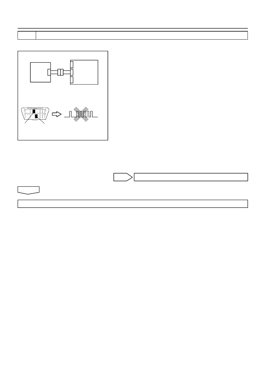
H02757
H10600 H01063
H02757
H10600 H01063
H40072
DTC B1156/B1157/15
DLC3
Tc
CG
Airbag
Sensor
Assy
Center
Airbag
Front RH
Sensor
–
DIAGNOSTICS
SUPPLEMENTAL RESTRAINT SYSTEM (April, 2003)
05–545
710
Author:
Date:
2004 COROLLA (RM1037U)
5
CHECK AIR BAG SENSOR ASSY CENTER
SST
09843–18040
(a)
Disconnect the negative (–) terminal cable from the bat-
tery, and wait at least for 90 seconds.
(b)
Connect the airbag front RH sensor connector and airbag
sensor assy center connector.
(c)
Connect the negative (–) terminal cable to the battery,
and wait at least for 2 seconds.
(d)
Turn the ignition switch to ON, and wait at least for 20 se-
conds.
(e)
Clear the DTC stored in memory (See page
05–424
).
(f)
Turn the ignition switch to LOCK, and wait at least for 20
seconds.
(g)
Turn the ignition switch to ON, and wait at least for 20 se-
conds.
(h)
Check the DTC (See page
05–424
).
OK:
DTC B1156/B1157/15 is not output.
HINT:
Codes other than code B1156/B1157/15 may be output at this
time, but they are not relevant to this check.
NG
REPLACE AIR BAG SENSOR ASSY CENTER
OK
USE SIMULATION METHOD TO CHECK
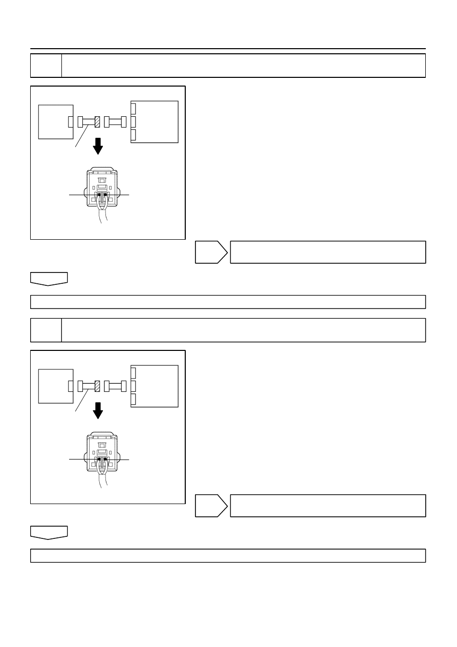
H41804
+SR
–SR
Airbag
Sensor
Assy
Center
Airbag
Front RH
Sensor
Engine Room
Main Wire
H41804
+SR
–SR
Airbag
Sensor
Assy
Center
Airbag
Front RH
Sensor
Engine Room
Main Wire
05–546
–
DIAGNOSTICS
SUPPLEMENTAL RESTRAINT SYSTEM (April, 2003)
711
Author:
Date:
2004 COROLLA (RM1037U)
6
CHECK ENGINE ROOM MAIN WIRE HARNESS (TO B+)(CONNECTOR – AIRBAG
FRONT RH SENSOR)
(a)
Turn the ignition switch to LOCK.
(b)
Disconnect the negative (–) terminal cable from the bat-
tery, and wait at least for 90 seconds.
(c)
Disconnect the connector between the engine room main
wire and the instrument panel wire.
(d)
Connect the negative (–) terminal cable to the battery,
and wait at least for 2 seconds.
(e)
Turn the ignition switch to ON.
(f)
For the engine room main wire connector (on the airbag
sensor assy center side) between the airbag sensor assy
center and the airbag front RH sensor, measure the volt-
age between body ground and each of +SR and –SR.
OK:
Voltage: Below 1 V
NG
REPAIR OR REPLACE ENGINE ROOM MAIN
WIRE
OK
REPAIR OR REPLACE INSTRUMENT PANEL WIRE
7
CHECK ENGINE ROOM MAIN WIRE HARNESS (TO GROUND)(CONNECTOR –
AIRBAG FRONT RH SENSOR)
(a)
Disconnect the connectors between the engine room
main wire and the instrument panel wire.
(b)
For the engine room main wire connector (on the airbag
sensor assy center side) between the airbag sensor assy
center and the airbag front RH sensor, measure the resis-
tance between body ground and each of +SR and –SR.
OK:
Resistance: 1 M
Ω
or Higher
NG
REPAIR OR REPLACE ENGINE ROOM MAIN
WIRE
OK
REPAIR OR REPLACE INSTRUMENT PANEL WIRE
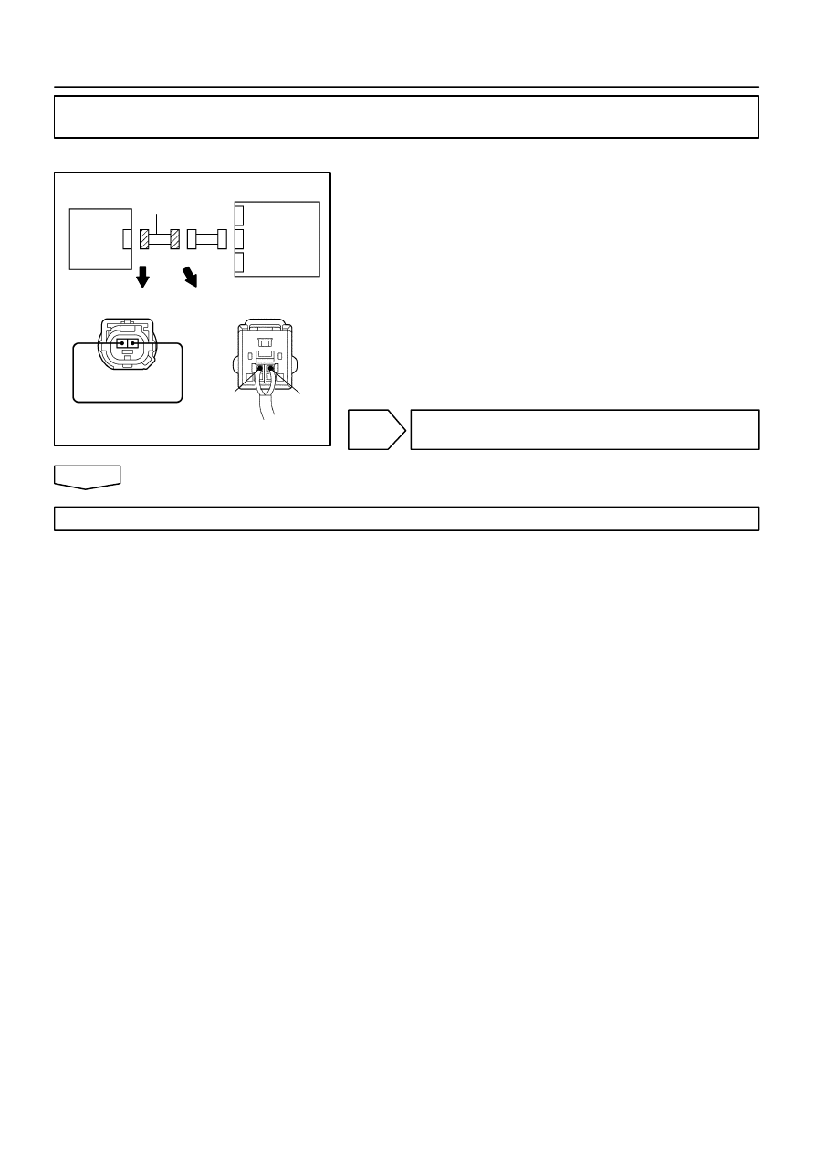
H41945
Airbag
Front
RH Sensor
Airbag
Sensor
Assy
Center
+SR
–SR
Engine Room
Main Wire
–
DIAGNOSTICS
SUPPLEMENTAL RESTRAINT SYSTEM (April, 2003)
05–547
712
Author:
Date:
2004 COROLLA (RM1037U)
8
CHECK ENGINE ROOM MAIN WIRE HARNESS(OPEN)(CONNECTOR – AIRBAG
FRONT RH SENSOR)
SST
09843–18040
(a)
Disconnect the connectors between the engine room
main wire and the instrument panel wire.
(b)
Using a service wire, connect +SR and –SR of the engine
room main wire connector (on the airbag front RH sensor
side) between the airbag sensor assy center and the air-
bag front RH sensor.
(c)
For the engine room main wire connector (on the airbag
sensor assy center side) between the airbag sensor assy
center and the airbag front RH sensor, measure the resis-
tance between the +SR and –SR.
OK:
Resistance: Below 1
Ω
NG
REPAIR OR REPLACE ENGINE ROOM MAIN
WIRE
OK
REPAIR OR REPLACE INSTRUMENT PANEL WIRE
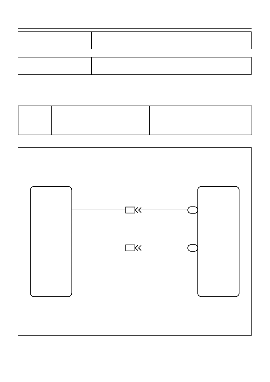
H02750
Airbag Sensor Assy Center
+SL
–SL
A13
15
26
W–R
BR
IA1
3
4
A5
Airbag Sensor Front LH
2
1
A13
+SL
–SL
W–R
BR
IA1
05–548
–
DIAGNOSTICS
SUPPLEMENTAL RESTRAINT SYSTEM (April, 2003)
713
Author:
Date:
2004 COROLLA (RM1037U)
DTC
B1158/16 FRONT AIRBAG SENSOR (LH)
MALFUNCTION
DTC
B1159/16 FRONT AIRBAG SENSOR (LH)
MALFUNCTION
CIRCUIT DESCRIPTION
The airbag sensor front LH circuit consists of the airbag sensor assy center and airbag sensor front LH.
DTC B1158/B1159/16 is recorded when malfunction is detected in the airbag sensor front LH circuit.
DTC No.
DTC Detecting Condition
Trouble Area
B1158/B1159/16
Airbag sensor front LH malfunction
Airbag sensor front LH
Airbag sensor assy center
Instrument panel wire
Engine room main wire
WIRING DIAGRAM
057UT–02
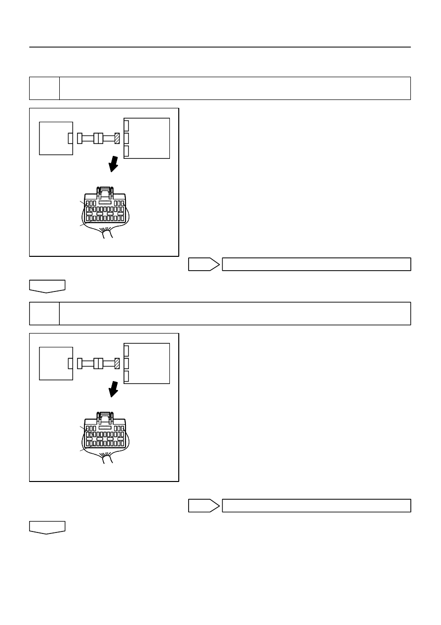
H03355
C81408
H03355
C81408
H40069
Airbag
Sensor
Assy
Center
+SL
–SL
Airbag
Sensor
Front LH
H03355
C81408
H03355
C81408
H40069
Airbag
Sensor
Assy
Center
+SL
–SL
Airbag
Sensor
Front LH
–
DIAGNOSTICS
SUPPLEMENTAL RESTRAINT SYSTEM (April, 2003)
05–549
714
Author:
Date:
2004 COROLLA (RM1037U)
INSPECTION PROCEDURE
1
CHECK FRONT AIRBAG SENSOR (LH) CIRCUIT (TO B+)(AIRBAG SENSOR ASSY
CENTER – AIRBAG SENSOR FRONT LH)
(a)
Disconnect the negative (–) terminal cable from the bat-
tery, and wait at least for 90 seconds.
(b)
Disconnect the connectors between the airbag sensor
assy center and the airbag sensor front LH.
(c)
Connect the negative (–) terminal cable to the battery,
and wait at least for 2 seconds.
(d)
Turn the ignition switch to ON.
(e)
For the connector (on the airbag sensor assy center side)
between the airbag sensor front LH and the airbag sensor
assy center, measure the voltage between body ground
and each of +SL and –SL.
OK:
Voltage: Below 1 V
NG
Go to step 6
OK
2
CHECK FRONT AIRBAG SENSOR(LH) CIRCUIT(TO GROUND)(AIRBAG SENSOR
ASSY CENTER – AIRBAG SENSOR FRONT LH)
(a)
Turn the ignition switch to LOCK.
(b)
Disconnect the negative (–) terminal cable from the bat-
tery, and wait at least for 90 seconds.
(c)
For the connector (on the airbag sensor assy center side)
between the airbag sensor front LH and the airbag sensor
assy center, measure the resistance between body
ground and each of +SL and –SL.
OK:
Resistance: 1 M
Ω
or Higher
NG
Go to step 7
OK
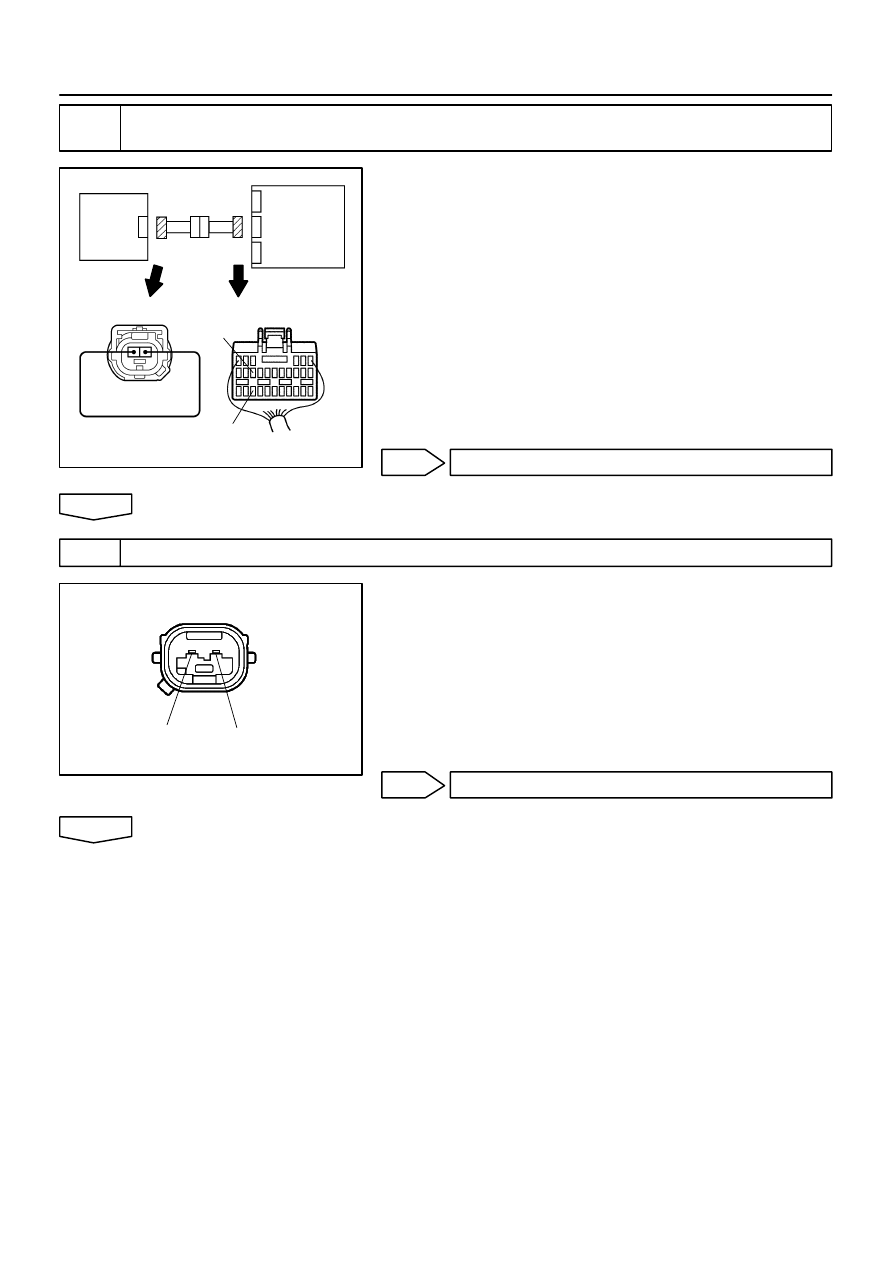
H03353
H03360 H08016
H41802
+SL
–SL
Airbag
Sensor
Assy
Center
Airbag
Sensor
Front LH
C54743
C54743
H40071
–SL
+SL
05–550
–
DIAGNOSTICS
SUPPLEMENTAL RESTRAINT SYSTEM (April, 2003)
715
Author:
Date:
2004 COROLLA (RM1037U)
3
CHECK FRONT AIRBAG SENSOR (LH) CIRCUIT(OPEN)(AIRBAG SENSOR ASSY
CENTER – AIRBAG SENSOR FRONT LH)
(a)
Using a service wire, connect +SL and –SL of the connec-
tor (on the airbag sensor front LH side) between the air-
bag sensor assy center and the airbag sensor front LH.
(b)
For the connector (on the airbag sensor assy center side)
between the airbag sensor front LH and the airbag sensor
assy center, measure the resistance between +SL and
–SL.
OK:
Resistance: Below 1
Ω
NG
Go to step 8
OK
4
INSPECT AIR BAG SENSOR FRONT LH
(a)
For the connector of the airbag sensor front LH, measure
the resistance between +SL and –SL.
OK:
Resistance: 820
Ω
NG
REPLACE AIR BAG SENSOR FRONT LH
OK
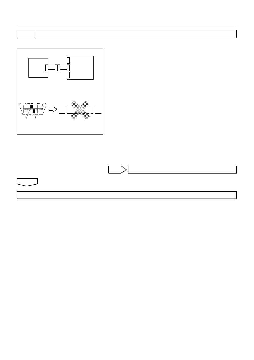
H02757
H10600 H01064
H02757
H10600 H01064
H40075
DLC3
CG
Tc
DTC B1158/B1159/16
Airbag
Sensor
Assy
Center
Airbag
Sensor
Front LH
–
DIAGNOSTICS
SUPPLEMENTAL RESTRAINT SYSTEM (April, 2003)
05–551
716
Author:
Date:
2004 COROLLA (RM1037U)
5
CHECK AIR BAG SENSOR ASSY CENTER
SST
09843–18040
(a)
Disconnect the negative (–) terminal cable from the bat-
tery, and wait at least for 90 seconds.
(b)
Connect the airbag sensor front LH connector and airbag
sensor assy center connector.
(c)
Connect the negative (–) terminal cable to the battery,
and wait at least for 2 seconds.
(d)
Turn the ignition switch to ON, and wait at least for 20 se-
conds.
(e)
Clear the DTC stored in memory (See page
05–424
).
(f)
Turn the ignition switch to LOCK, and wait at least for 20
seconds.
(g)
Turn the ignition switch to ON, and wait at least for 20 se-
conds.
(h)
Check the DTC (See page
05–424
).
OK:
DTC B1158/B1159/16 is not output.
HINT:
Codes other than code B1158/B1159/16 may be output at this
time, but they are not relevant to this check.
NG
REPLACE AIR BAG SENSOR ASSY CENTER
OK
USE SIMULATION METHOD TO CHECK
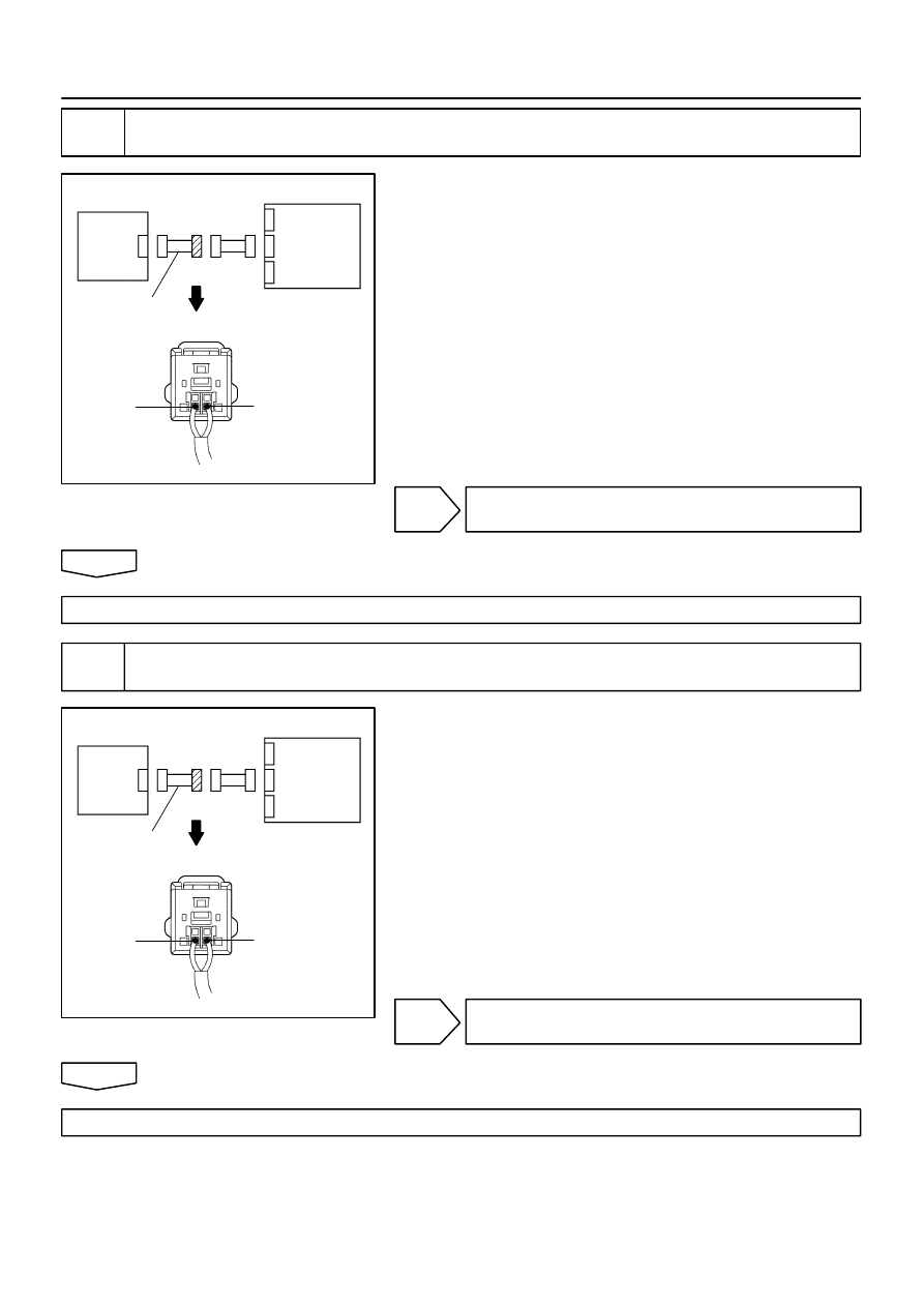
H03354
H40556
H40558
+SL
–SL
Airbag
Sensor
Assy
Center
Airbag
Sensor
Front LH
Engine Room
Main Wire
H03354
H40556
H40558
+SL
–SL
Airbag
Sensor
Assy
Center
Airbag
Sensor
Front LH
Engine Room
Main Wire
05–552
–
DIAGNOSTICS
SUPPLEMENTAL RESTRAINT SYSTEM (April, 2003)
717
Author:
Date:
2004 COROLLA (RM1037U)
6
CHECK ENGINE ROOM MAIN WIRE HARNESS (TO B+)(CONECTOR – AIRBAG
SENSOR FRONT LH)
(a)
Turn the ignition switch to LOCK.
(b)
Disconnect the negative (–) terminal cable from the bat-
tery, and wait at least for 90 seconds.
(c)
Disconnect the connector between the engine room main
wire and the instrument panel wire.
(d)
Connect the negative (–) terminal to the battery, and wait
at least for 2 seconds.
(e)
Turn the ignition switch to ON.
(f)
For the engine room main wire connector (on the airbag
sensor assy center side) between the airbag sensor assy
center and the airbag sensor front LH, measure the volt-
age between body ground and each of +SL and –SL.
OK:
Voltage: Below 1 V
NG
REPAIR OR REPLACE ENGINE ROOM MAIN
WIRE
OK
REPAIR OR REPLACE INSTRUMENT PANEL WIRE
7
CHECK ENGINE ROOM MAIN WIRE HARNESS (TO GROUND)(CONNECTOR –
AIRBAG SENSOR FRONT LH)
(a)
Disconnect the connectors between the engine room
main wire and the instrument panel wire.
(b)
For the engine room main wire connector (on the airbag
sensor assy center side) between the airbag sensor assy
center and the airbag sensor front LH, measure the resis-
tance between body ground and each of +SL and –SL.
OK:
Resistance: 1 M
Ω
or Higher
NG
REPAIR OR REPLACE ENGINE ROOM MAIN
WIRE
OK
REPAIR OR REPLACE INSTRUMENT PANEL WIRE
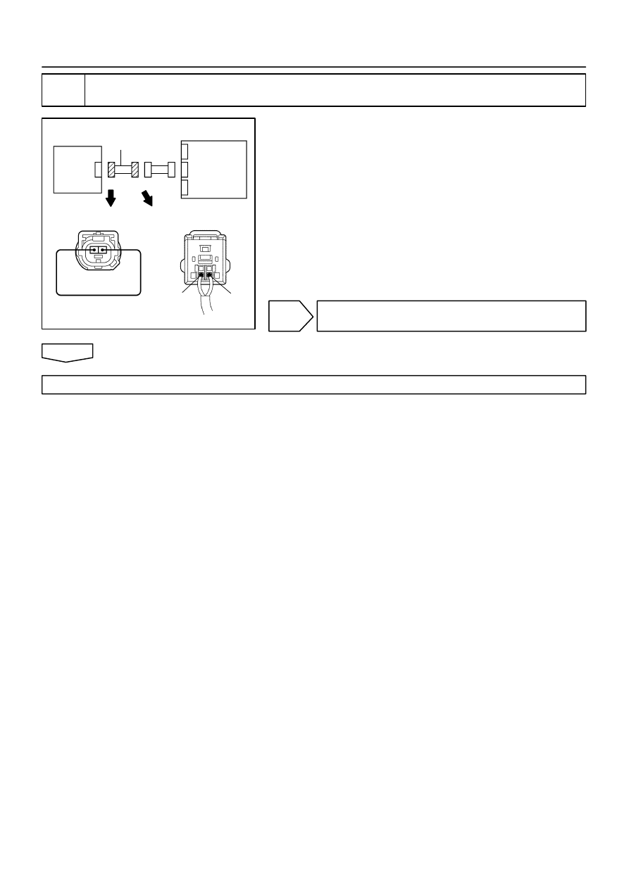
H03352
H40556
H08016
H41801
Airbag
Sensor
Front LH
Airbag
Sensor
Assy
Center
+SL
–SL
Engine Room
Main Wire
–
DIAGNOSTICS
SUPPLEMENTAL RESTRAINT SYSTEM (April, 2003)
05–553
718
Author:
Date:
2004 COROLLA (RM1037U)
8
CHECK ENGINE ROOM MAIN WIRE HARNESS(OPEN)(CONNECTOR – AIRBAG
SENSOR FRONT LH)
(a)
Disconnect the connectors between the engine room
main wire and the instrument panel wire.
(b)
Using a service wire, connect +SL and –SL of the engine
room main wire connector (on the airbag sensor front LH
side) between the airbag sensor assy center and the air-
bag sensor front LH.
(c)
For the engine room main wire connector (on the airbag
sensor assy center side) between the airbag sensor assy
center and the airbag sensor front LH, measure the resis-
tance between +SL and –SL.
OK:
Resistance: Below 1
Ω
NG
REPAIR OR REPLACE ENGINE ROOM MAIN
WIRE
OK
REPAIR OR REPLACE INSTRUMENT PANEL WIRE

H01451
Airbag Sensor Assy Center
A16
D Squib (2nd step)
Spiral Cable
Sub–Assy
Y–O
Y–V
D2+
D2–
4
A13
3
A13
17
16
D+
D–
05–554
–
DIAGNOSTICS
SUPPLEMENTAL RESTRAINT SYSTEM (April, 2003)
719
Author:
Date:
2004 COROLLA (RM1037U)
DTC
B1180/17 SHORT IN D SQUIB (2ND STEP) CIRCUIT
CIRCUIT DESCRIPTION
The D squib circuit consists of the airbag sensor assy center, spiral cable sub–assy and horn button assy.
It causes the SRS to deploy when the SRS deployment conditions are satisfied.
DTC B1180/17 is recorded when a short is detected in the D squib circuit (2nd step).
DTC No.
DTC Detecting Condition
Trouble Area
B1180/17
Short circuit between D2+ wire harness and D2– wire
harness of squib (2nd step)
D squib (2nd step) malfunction
Spiral cable sub–assy malfunction
Airbag sensor assy center malfunction
Horn button assy (D squib, 2nd step)
Spiral cable sub–assy
Airbag sensor assy center
Instrument panel wire
WIRING DIAGRAM
055ZL–04
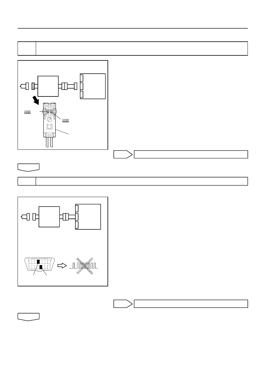
H01001
C89244
H41475
D Squib
Airbag
Sensor
Assy
Center
Spiral
Cable
Sub–Assy
Color: Black
H01002
H10600 C89246
H42137
D Squib
Airbag
Sensor
Assy
Center
Spiral
Cable
Sub–Assy
DLC3
CG
Tc
DTC B1180/17
–
DIAGNOSTICS
SUPPLEMENTAL RESTRAINT SYSTEM (April, 2003)
05–555
720
Author:
Date:
2004 COROLLA (RM1037U)
INSPECTION PROCEDURE
1
CHECK D SQUIB CIRCUIT(AIRBAG SENSOR ASSY CENTER – HORN BUTTON
ASSY)
(a)
Disconnect the negative (–) terminal cable from the bat-
tery, and wait at least for 90 seconds.
(b)
Disconnect the connectors between the airbag sensor
assy center and the horn button assy.
(c)
Release the airbag activation prevention mechanism of
the connector (on the airbag sensor assy center side) be-
tween the airbag sensor assy center and the spiral cable
sub–assy (See page
05–424
).
(d)
For the black connector (on the spiral cable sub–assy
side ) between the horn button assy and the spiral cable
sub–assy, measure the resistance between D2+ and
D2–.
OK:
Resistance: 1 M
Ω
or Higher
NG
Go to step 4
OK
2
CHECK AIR BAG SENSOR ASSY CENTER
SST
09843–18040
(a)
Connect the connector to the airbag sensor assy center.
(b)
Connect the negative (–) terminal cable to the battery,
and wait at least for 2 seconds.
(c)
Turn the ignition switch to ON, and wait at least for 20 se-
conds.
(d)
Clear the DTC stored in memory (See page
05–424
).
(e)
Turn the ignition switch to LOCK, and wait at least for 20
seconds.
(f)
Turn the ignition switch to ON, and wait at least for 20 se-
conds.
(g)
Check the DTC (See page
05–424
).
OK:
DTC B1180/17 is not output.
HINT:
Codes other than code B1180/17 may be output at this time, but
they are not relevant to this check.
NG
REPLACE AIR BAG SENSOR ASSY CENTER
OK
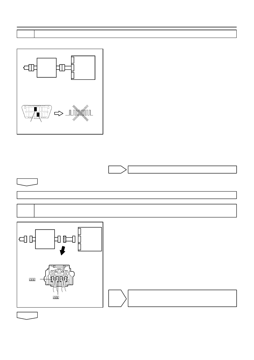
H01003
H10600 C89246
H42138
D Squib
Airbag
Sensor
Assy
Center
Spiral
Cable
Sub–Assy
DLC3
CG
Tc
DTC B1180/17
H01004
H41424
H41478
D Squib
Airbag
Sensor
Assy
Center
Spiral
Cable
Sub–Assy
05–556
–
DIAGNOSTICS
SUPPLEMENTAL RESTRAINT SYSTEM (April, 2003)
721
Author:
Date:
2004 COROLLA (RM1037U)
3
CHECK D SQUIB
SST
09843–18040
(a)
Turn the ignition switch to LOCK.
(b)
Disconnect the negative (–) terminal cable from the bat-
tery, and wait at least for 90 seconds.
(c)
Connect the horn button assy connectors.
(d)
Connect the negative (–) terminal cable to the battery,
and wait at least for 2 seconds.
(e)
Turn the ignition switch to ON, and wait at least for 20 se-
conds.
(f)
Clear the DTC stored in memory (See page
05–424
).
(g)
Turn the ignition switch to LOCK, and wait at least for 20
seconds.
(h)
Turn the ignition switch to ON, and wait at least for 20 se-
conds.
(i)
Check the DTC (See page
05–424
).
OK:
DTC B1180/17 is not output.
HINT:
Codes other than code B1180/17 may be output at this time, but
they are not relevant to this check.
NG
REPLACE HORN BUTTON ASSY
OK
USE SIMULATION METHOD TO CHECK
4
CHECK INSTRUMENT PANEL WIRE(AIRBAG SENSOR ASSY CENTER – SPIRAL
CABLE SUB–ASSY)
(a)
Disconnect the connector of the instrument panel wire.
(b)
Release the airbag activation prevention mechanism of
the connector (on the airbag sensor assy center side) be-
tween the airbag sensor assy center and the spiral cable
sub–assy (See page
05–424
).
(c)
For the connector (on the spiral cable sub–assy side) be-
tween the airbag sensor assy center and the spiral cable
sub–assy, measure the resistance between D2+ and
D2–.
OK:
Resistance: 1 M
Ω
or Higher
NG
REPAIR OR REPLACE INSTRUMENT PANEL
WIRE(AIRBAG SENSOR ASSY CENTER – SPI-
RAL CABLE SUB–ASSY)
OK
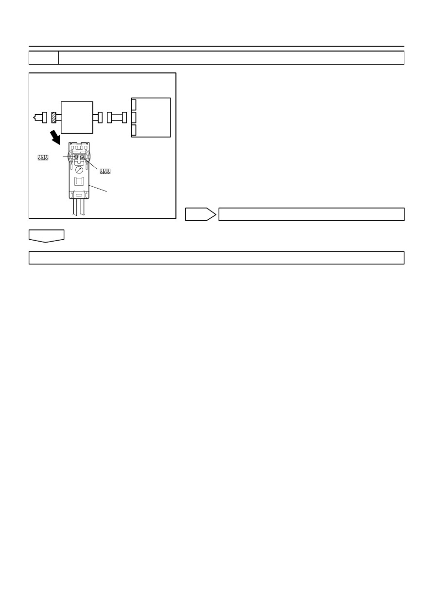
H01000
C89244
H41479
D Squib
Airbag
Sensor
Assy
Center
Spiral
Cable
Sub–Assy
Color: Black
–
DIAGNOSTICS
SUPPLEMENTAL RESTRAINT SYSTEM (April, 2003)
05–557
722
Author:
Date:
2004 COROLLA (RM1037U)
5
CHECK SPIRAL CABLE SUB–ASSY
(a)
Release the airbag activation prevention mechanism of
the spiral cable sub–assy connector on the airbag sensor
assy center side (See page
05–424
).
(b)
For the black connector (on the spiral cable sub–assy
side) between the horn button assy and the spiral cable
sub–assy, measure the resistance between D2+ and
D2–.
OK:
Resistance: 1 M
Ω
or Higher
NG
REPLACE SPIRAL CABLE SUB–ASSY
OK
USE SIMULATION METHOD TO CHECK

H01001
C89244
H41475
D Squib
Airbag
Sensor
Assy
Center
Spiral
Cable
Sub–Assy
Color: Black
05–558
–
DIAGNOSTICS
SUPPLEMENTAL RESTRAINT SYSTEM (April, 2003)
723
Author:
Date:
2004 COROLLA (RM1037U)
DTC
B1181/18 OPEN IN D SQUIB (2ND STEP) CIRCUIT
CIRCUIT DESCRIPTION
The D squib circuit consists of the airbag sensor assy center, spiral cable sub–assy and horn button assy.
It causes the SRS to deploy when the SRS deployment conditions are satisfied.
DTC B1181/18 is recorded when an open is detected in the D squib circuit (2nd step).
DTC No.
DTC Detecting Condition
Trouble Area
B1181/18
Open circuit in D+ wire harness or D– wire harness of squib
D squib (2nd step) malfunction
Spiral cable sub–assy malfunction
Airbag sensor assy center malfunction
Horn button assy (D squib, 2nd step)
Spiral cable sub–assy
Airbag sensor assy center
Instrument panel wire
WIRING DIAGRAM
See page
05–554
.
INSPECTION PROCEDURE
1
CHECK D SQUIB CIRCUIT(AIRBAG SENSOR ASSY CENTER – HORN BUTTON
ASSY)
(a)
Disconnect the negative (–) terminal cable from the bat-
tery, and wait at least for 90 seconds.
(b)
Disconnect the connectors between the horn button assy
and the airbag sensor assy center.
(c)
For the black connector (on the spiral cable sub–assy
side) between the horn button assy and the spiral cable
sub–assy, measure the resistance between D2+ and
D2–.
OK:
Resistance: Below 1
Ω
NG
Go to step 4
OK
055ZM–04
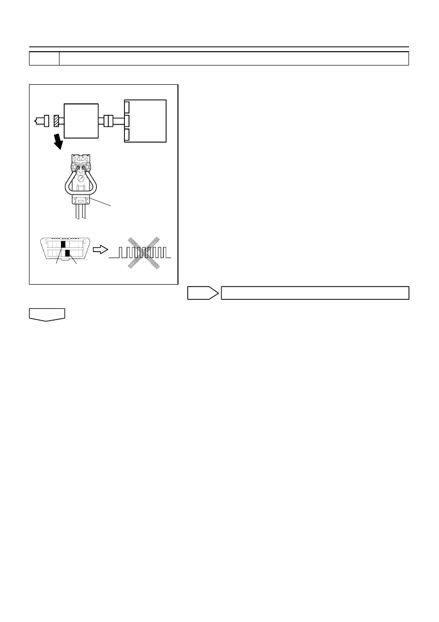
H01002
H10600
C89252
C89253
H42139
D Squib
Airbag
Sensor
Assy
Center
Spiral
Cable
Sub–Assy
Color: Black
DLC3
CG
Tc
DTC B1181/18
–
DIAGNOSTICS
SUPPLEMENTAL RESTRAINT SYSTEM (April, 2003)
05–559
724
Author:
Date:
2004 COROLLA (RM1037U)
2
CHECK AIR BAG SENSOR ASSY CENTER
SST
09843–18040
(a)
Connect the connector to the airbag sensor assy center.
(b)
Using a service wire, connect D2+ and D2– of the black
connector (on the spiral cable sub–assy side) between
the horn button assy and the spiral cable sub–assy.
(c)
Connect the negative (–) terminal cable to the battery,
and wait at least for 2 seconds.
(d)
Turn the ignition switch to ON, and wait at least for 20 se-
conds.
(e)
Clear the DTC stored in memory (See page
05–424
).
(f)
Turn the ignition switch to LOCK, and wait at least for 20
seconds.
(g)
Turn the ignition switch to ON, and wait at least for 20 se-
conds.
(h)
Check the DTC (See page
05–424
).
OK:
DTC B1181/18 is not output.
HINT:
Codes other than code B1181/18 may be output at this time, but
they are not relevant to this check.
NG
REPLACE AIR BAG SENSOR ASSY CENTER
OK
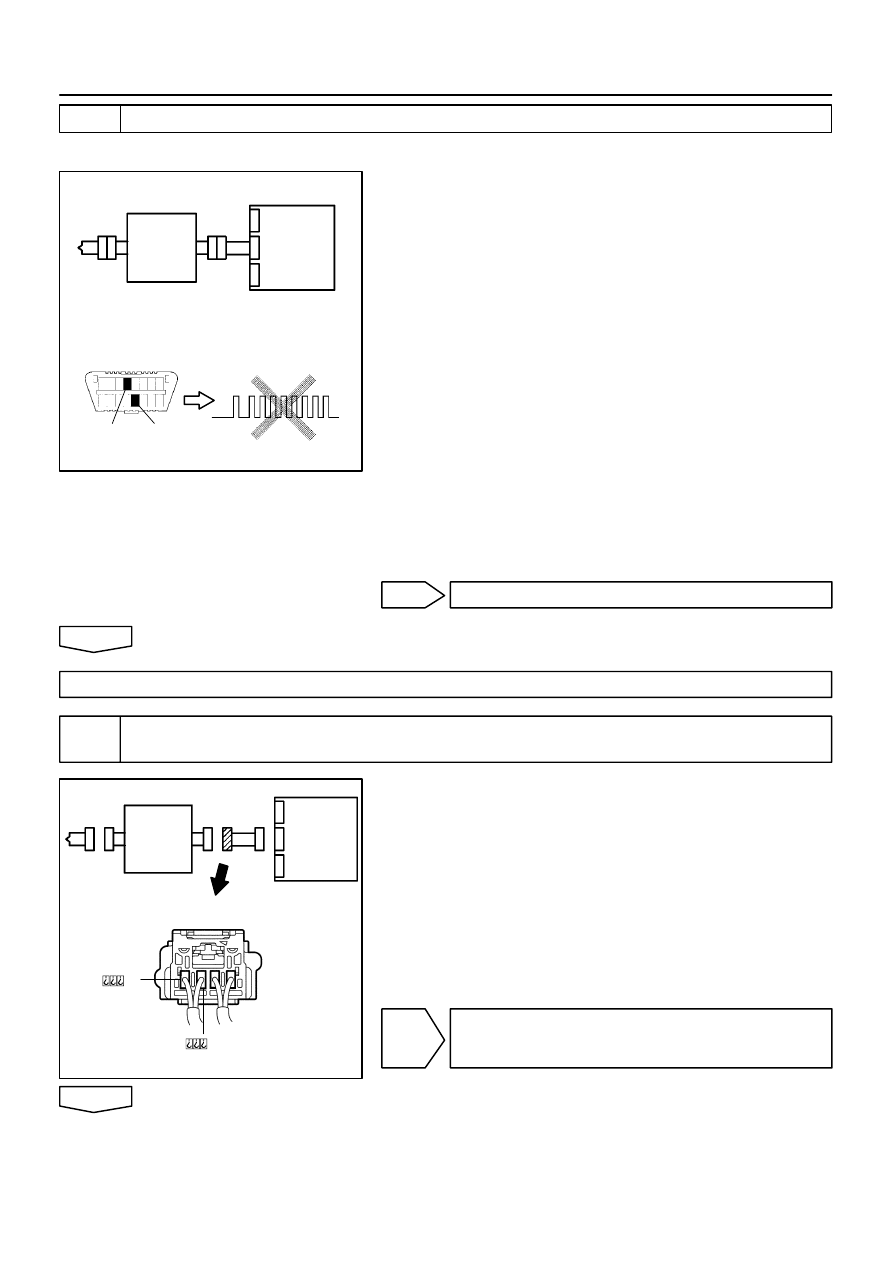
H01003
H10600 C89253
H42140
D Squib
Airbag
Sensor
Assy
Center
Spiral
Cable
Sub–Assy
DLC3
CG
Tc
DTC B1181/18
H01004
H41424
H41478
D Squib
Airbag
Sensor
Assy
Center
Spiral
Cable
Sub–Assy
05–560
–
DIAGNOSTICS
SUPPLEMENTAL RESTRAINT SYSTEM (April, 2003)
725
Author:
Date:
2004 COROLLA (RM1037U)
3
CHECK D SQUIB
SST
09843–18040
(a)
Turn the ignition switch to LOCK.
(b)
Disconnect the negative (–) terminal cable from the bat-
tery, and wait at least for 90 seconds.
(c)
Connect the horn button assy connectors.
(d)
Connect the negative (–) terminal cable to the battery,
and wait at least for 2 seconds.
(e)
Turn the ignition switch to ON, and wait at least for 20 se-
conds.
(f)
Clear the DTC stored in memory (See page
05–424
).
(g)
Turn the ignition switch to LOCK, and wait at least for 20
seconds.
(h)
Turn the ignition switch to ON, and wait at least for 20 se-
conds.
(i)
Check the DTC (See page
05–424
).
OK:
DTC B1181/18 is not output.
HINT:
Codes other than code B1181/18 may be output at this time, but
they are not relevant to this check.
NG
REPLACE HORN BUTTON ASSY
OK
USE SIMULATION METHOD TO CHECK
4
CHECK INSTRUMENT PANEL WIRE(AIRBAG SENSOR ASSY CENTER – SPIRAL
CABLE SUB–ASSY)
(a)
Disconnect the connector of the instrument panel wire.
(b)
For the connector (on the spiral cable sub–assy side) be-
tween the airbag sensor assy center and the spiral cable
sub–assy, measure the resistance between D2+ and
D2–.
OK:
Resistance: Below 1
Ω
NG
REPAIR OR REPLACE INSTRUMENT PANEL
WIRE(AIRBAG SENSOR ASSY CENTER – SPI-
RAL CABLE SUB–ASSY)
OK
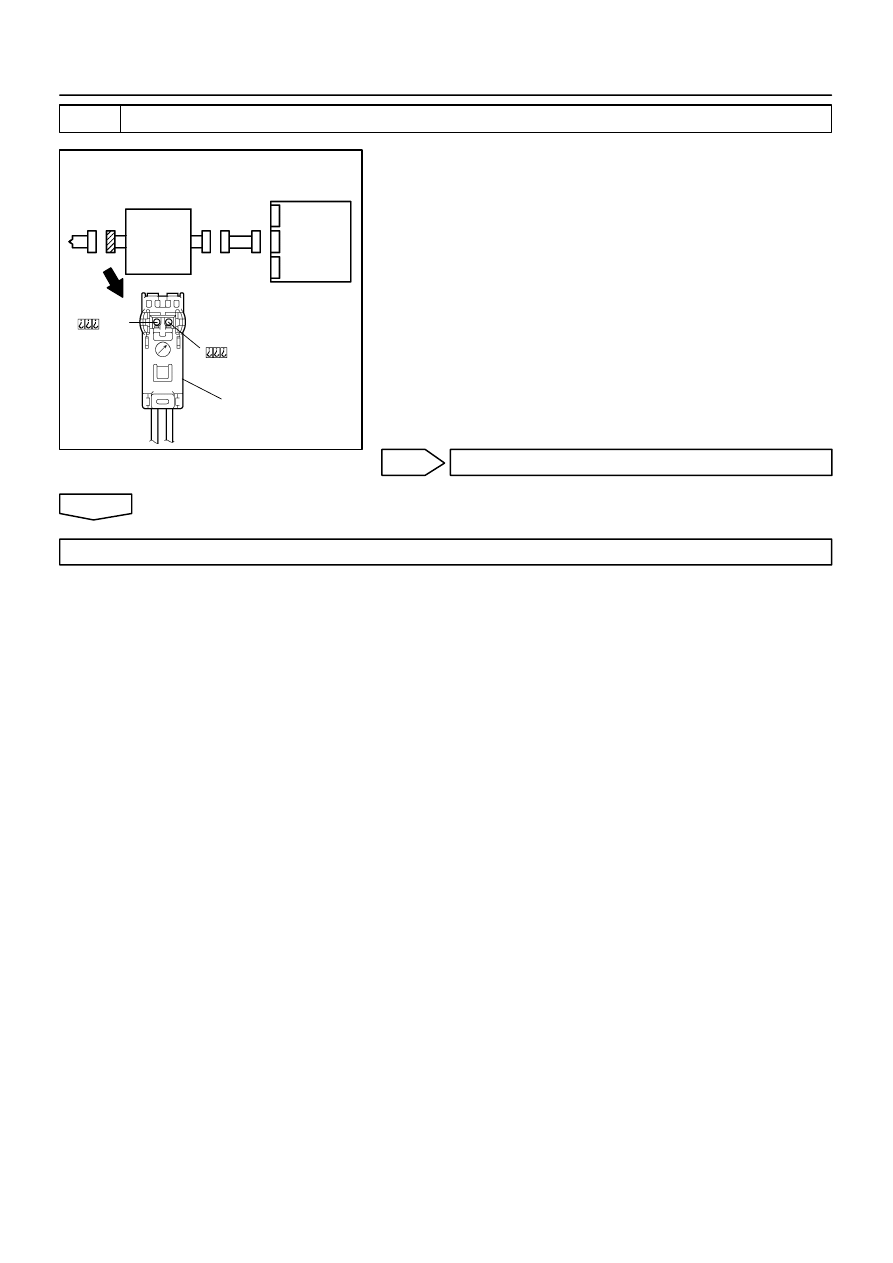
H01000
C89244
H41479
D Squib
Airbag
Sensor
Assy
Center
Spiral
Cable
Sub–Assy
Color: Black
–
DIAGNOSTICS
SUPPLEMENTAL RESTRAINT SYSTEM (April, 2003)
05–561
726
Author:
Date:
2004 COROLLA (RM1037U)
5
CHECK SPIRAL CABLE SUB–ASSY
(a)
For the black connector (on the spiral cable sub–assy
side) between the horn button assy and the spiral cable
sub–assy, measure the resistance between D2+ and
D2–.
OK:
Resistance: Below 1
Ω
NG
REPLACE SPIRAL CABLE SUB–ASSY
OK
USE SIMULATION METHOD TO CHECK
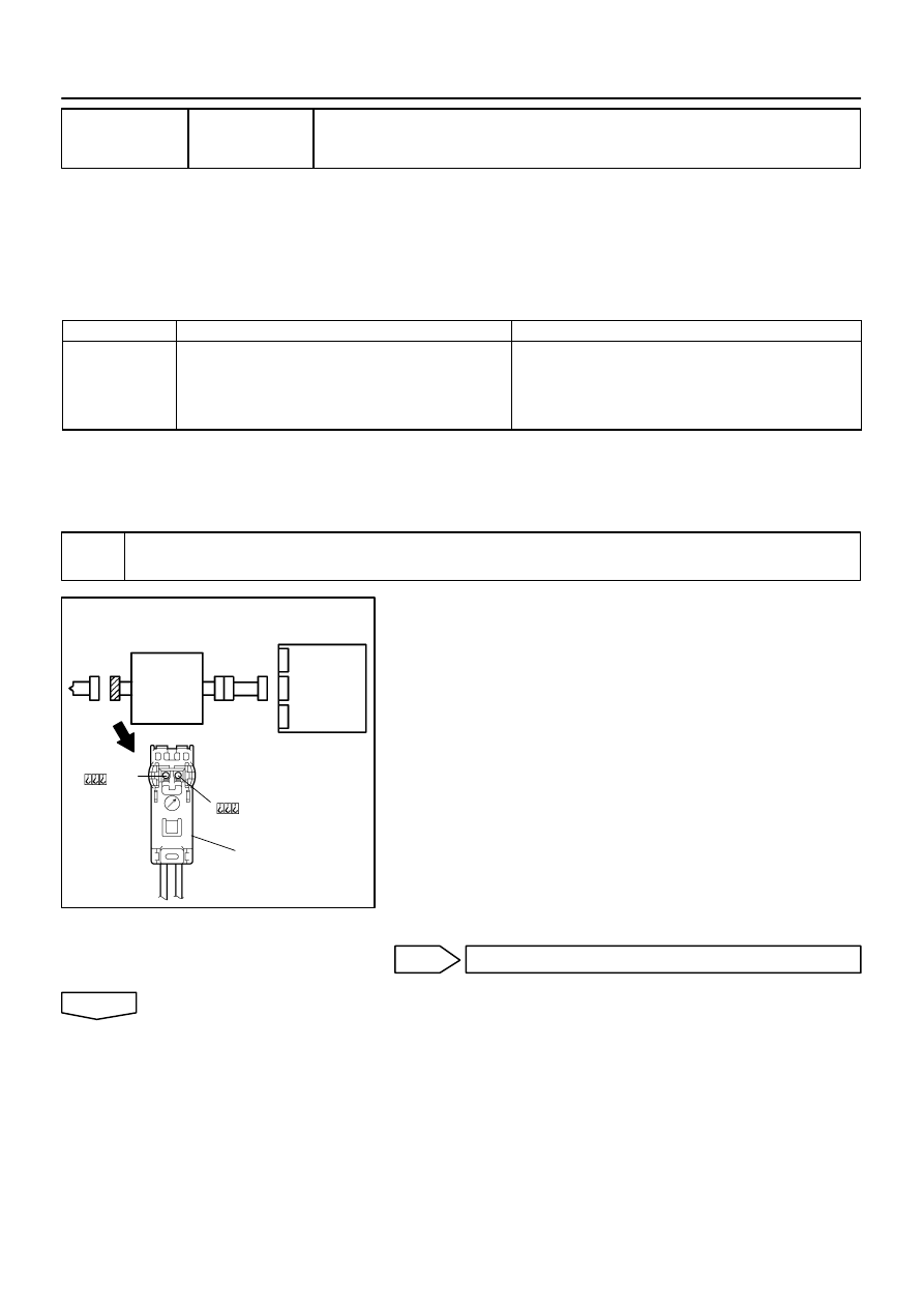
H01001
C89244
H41475
D Squib
Airbag
Sensor
Assy
Center
Spiral
Cable
Sub–Assy
Color: Black
05–562
–
DIAGNOSTICS
SUPPLEMENTAL RESTRAINT SYSTEM (April, 2003)
727
Author:
Date:
2004 COROLLA (RM1037U)
DTC
B1182/19 SHORT IN D SQUIB (2ND STEP) CIRCUIT
(TO GROUND)
CIRCUIT DESCRIPTION
The D squib (2nd step) circuit consists of the airbag sensor assy center, spiral cable sub–assy and horn but-
ton assy.
It causes the SRS to deploy when the SRS deployment conditions are satisfied.
DTC B1182/19 is recorded when a ground short is detected in the D squib (2nd step) circuit.
DTC No.
DTC Detecting Condition
Trouble Area
B1182/19
Short circuit in D squib (2nd step) wire harness (to
ground)
D squib (2nd step) malfunction
Spiral cable sub–assy malfunction
Airbag sensor assy center malfunction
Horn button assy (D squib, 2nd step)
Spiral cable sub–assy
Airbag sensor assy center
Instrument panel wire
WIRING DIAGRAM
See page
05–554
.
INSPECTION PROCEDURE
1
CHECK D SQUIB CIRCUIT(AIRBAG SENSOR ASSY CENTER – HORN BUTTON
ASSY)
(a)
Disconnect the negative (–) terminal cable from the bat-
tery, and wait at least for 90 seconds.
(b)
Disconnect the connector between the airbag sensor
assy center and the horn button assy.
(c)
For the black connector (on the spiral cable sub–assy
side) between the horn button assy and the spiral cable
sub–assy, measure the resistance between D2+ and
body ground.
OK:
Resistance: 1 M
Ω
or Higher
NG
Go to step 5
OK
055ZN–05
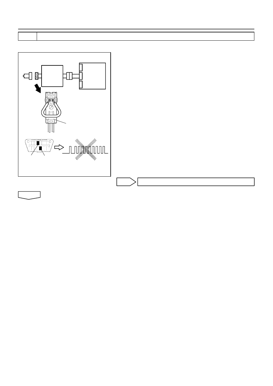
H01002
C89252
H10600 C91338
H42141
D Squib
Airbag
Sensor
Assy
Center
Spiral
Cable
Sub–Assy
Color: Black
DLC3
CG
Tc
DTC B1182/19
–
DIAGNOSTICS
SUPPLEMENTAL RESTRAINT SYSTEM (April, 2003)
05–563
728
Author:
Date:
2004 COROLLA (RM1037U)
2
CHECK AIR BAG SENSOR ASSY CENTER
SST
09843–18040
(a)
Connect the connector to the airbag sensor assy center.
(b)
Using a service wire, connect D2+ and D2– of the black
connector (on the spiral cable sub–assy side) between
the horn button assy and the spiral cable sub–assy.
(c)
Connect the negative (–) terminal cable to the battery,
and wait at least for 2 seconds.
(d)
Turn the ignition switch to ON, and wait t least for 20 se-
conds.
(e)
Clear the DTC stored in memory (See page
05–424
).
(f)
Turn the ignition switch to LOCK, and wait at least for 20
seconds.
(g)
Turn the ignition switch to ON, and wait at least for 20 se-
conds.
(h)
Check the DTC (See page
05–424
).
OK:
DTC B1182/19 is not output.
HINT:
Codes other than code B1182/19 may be output at this time, but
they are not relevant to this check.
NG
REPLACE AIR BAG SENSOR ASSY CENTER
OK

H01003
H10600 C89253
H42142
D Squib
Airbag
Sensor
Assy
Center
Spiral
Cable
Sub–Assy
DLC3
CG
Tc
DTC B1182/19
05–564
–
DIAGNOSTICS
SUPPLEMENTAL RESTRAINT SYSTEM (April, 2003)
729
Author:
Date:
2004 COROLLA (RM1037U)
3
CHECK D SQUIB
SST
09843–18040
(a)
Turn the ignition switch to LOCK.
(b)
Disconnect the negative (–) terminal cable from the bat-
tery, and wait at least for 90 seconds.
(c)
Connect the horn button assy connectors.
(d)
Connect the negative (–) terminal cable to the battery,
and wait at least for 2 seconds.
(e)
Turn the ignition switch to ON, and wait at least for 20 se-
conds.
(f)
Clear the DTC stored in memory (See page
05–424
).
(g)
Turn the ignition switch to LOCK, and wait at least for 20
seconds.
(h)
Turn the ignition switch to ON, and wait at least for 20 se-
conds.
(i)
Check the DTC (See page
05–424
).
OK:
DTC B1182/19 is not output.
HINT:
Codes other than code B1182/19 may be output at this time, but
they are not relevant to this check.
NG
REPLACE HORN BUTTON ASSY
OK
4
USE SIMULATION METHOD TO CHECK
NG
Go to step 1
OK
REPLACE ALL SRS COMPONENTS INCLUDING THE WIRE HARNESS
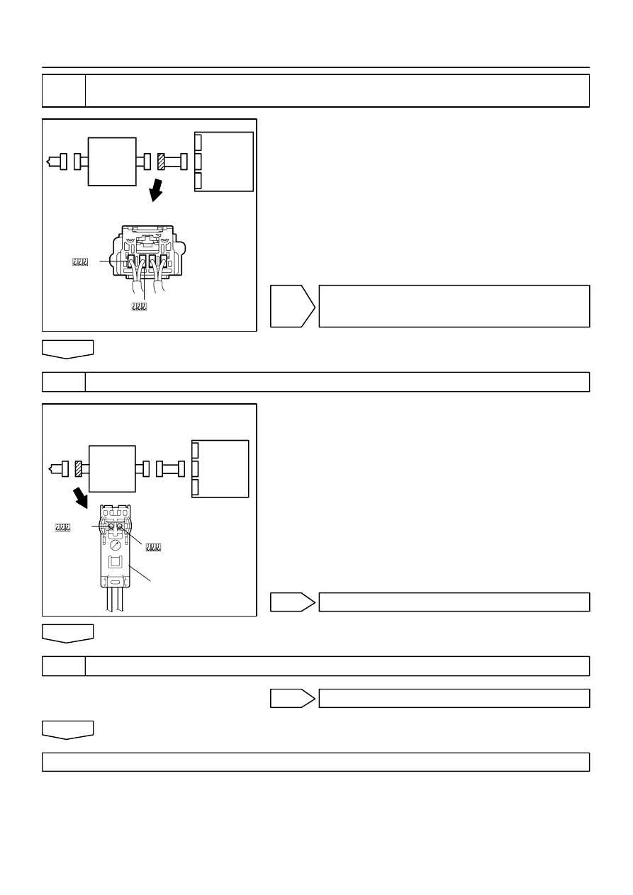
H01004
H41424
H41478
D Squib
Airbag
Sensor
Assy
Center
Spiral
Cable
Sub–Assy
H01000
C89244
H41479
D Squib
Airbag
Sensor
Assy
Center
Spiral
Cable
Sub–Assy
Color: Black
–
DIAGNOSTICS
SUPPLEMENTAL RESTRAINT SYSTEM (April, 2003)
05–565
730
Author:
Date:
2004 COROLLA (RM1037U)
5
CHECK INSTRUMENT PANEL WIRE(AIRBAG SENSOR ASSY CENTER – SPIRAL
CABLE SUB–ASSY)
(a)
Disconnect the connector of the instrument panel wire.
(b)
For the connector (on the spiral cable sub–assy side) be-
tween the airbag sensor assy center and the spiral cable
sub–assy, measure the resistance between D2+ and
body ground.
OK:
Resistance: 1 M
Ω
or Higher
NG
REPAIR OR REPLACE INSTRUMENT PANEL
WIRE(AIRBAG SENSOR ASSY CENTER – SPI-
RAL CABLE SUB–ASSY)
OK
6
CHECK SPIRAL CABLE SUB–ASSY
(a)
For the black connector (on the spiral cable sub–assy
side) between the horn button assy and the spiral cable
sub–assy, measure the resistance between D2+ and
body ground.
OK:
Resistance: 1 M
Ω
or Higher
NG
REPLACE SPIRAL CABLE SUB–ASSY
OK
7
USE SIMULATION METHOD TO CHECK
NG
Go to step 1
OK
REPLACE ALL SRS COMPONENTS INCLUDING THE WIRE HARNESS
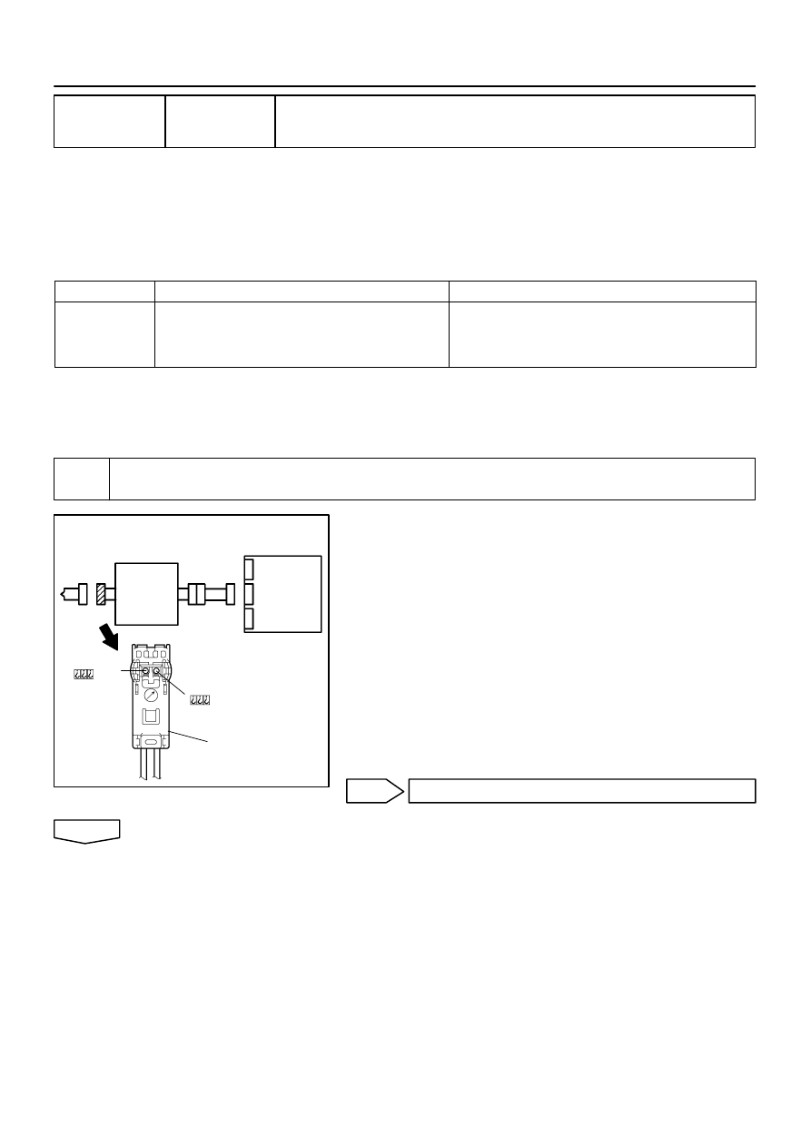
H01001
C89244
H41475
D Squib
Airbag
Sensor
Assy
Center
Spiral
Cable
Sub–Assy
Color: Black
05–566
–
DIAGNOSTICS
SUPPLEMENTAL RESTRAINT SYSTEM (April, 2003)
731
Author:
Date:
2004 COROLLA (RM1037U)
DTC
B1183/22 SHORT IN D SQUIB (2ND STEP) CIRCUIT
(TO B+)
CIRCUIT DESCRIPTION
The D squib (2nd step) circuit consists of the airbag sensor assy center, spiral cable sub–assy and horn but-
ton assy.
It causes the SRS to deploy when the SRS deployment conditions are satisfied.
DTC B1183/22 is recorded when a B+ short is detected in the D squib (2nd step) circuit.
DTC No.
DTC Detecting Condition
Trouble Area
B1183/22
Short circuit in D squib (2nd step) wire harness (to B+)
D squib (2nd step) malfunction
Spiral cable sub–assy malfunction
Airbag sensor assy center malfunction
Horn button assy (D squib, 2nd step)
Spiral cable sub–assy
Airbag sensor assy center
Instrument panel wire
WIRING DIAGRAM
See page
05–424
.
CIRCUIT INSPECTION
1
CHECK D SQUIB CIRCUIT(AIRBAG SENSOR ASSY CENTER – HORN BUTTON
ASSY)
(a)
Disconnect the negative (–) terminal cable from the bat-
tery, and wait at least for 90 seconds.
(b)
Disconnect the connectors between the airbag sensor
assy center and the horn button assy.
(c)
Connect the negative (–) terminal cable to the battery,
and wait at least for 2 seconds.
(d)
Turn the ignition switch to ON.
(e)
For the black connector (on the spiral cable sub–assy
side) between the horn button assy and the spiral cable
sub–assy, measure the voltage between D2+ and body
ground.
OK:
Voltage: Below 1 V
NG
Go to step 5
OK
055ZO–04
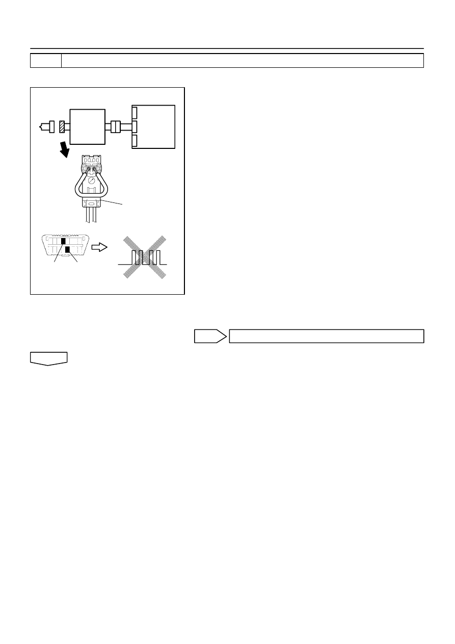
H01002
C89252
H10600 C91342
H42143
D Squib
Airbag
Sensor
Assy
Center
Spiral
Cable
Sub–Assy
Color: Black
DLC3
CG
Tc
DTC B1183/22
–
DIAGNOSTICS
SUPPLEMENTAL RESTRAINT SYSTEM (April, 2003)
05–567
732
Author:
Date:
2004 COROLLA (RM1037U)
2
CHECK AIR BAG SENSOR ASSY CENTER
SST
09843–18040
(a)
Turn the ignition switch to LOCK.
(b)
Disconnect the negative (–) terminal cable from the bat-
tery, and wait at least for 90 seconds.
(c)
Connect the connector to the airbag sensor assy center.
(d)
Using a service wire, connect D2+ and D2– of the black
connector (on the spiral cable sub–assy side) between
the horn button assy and the spiral cable sub–assy.
(e)
Connect the negative (–) terminal cable to the battery,
and wait at least for 2 seconds.
(f)
Turn the ignition switch to ON, and wait at least for 20 se-
conds.
(g)
Clear the DTC stored in memory (See page
05–424
).
(h)
Turn the ignition switch to LOCK, and wait at least for 20
seconds.
(i)
Turn the ignition switch to ON, and wait at least for 20 se-
conds.
(j)
Check the DTC (See page
05–424
).
OK:
DTC B1183/22 is not output.
HINT:
Codes other than code B1183/22 may be output at this time, but
they are not relevant to this check.
NG
REPLACE AIR BAG SENSOR ASSY CENTER
OK
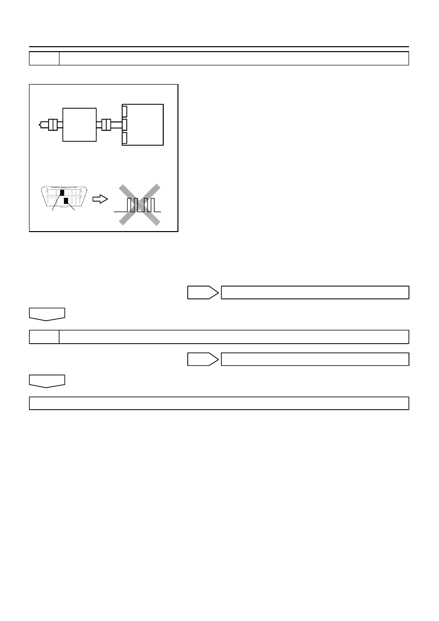
H01003
H10600 C91342
H42144
D Squib
Airbag
Sensor
Assy
Center
Spiral
Cable
Sub–Assy
DLC3
CG
Tc
DTC B1183/22
05–568
–
DIAGNOSTICS
SUPPLEMENTAL RESTRAINT SYSTEM (April, 2003)
733
Author:
Date:
2004 COROLLA (RM1037U)
3
CHECK D SQUIB
SST
09843–18040
(a)
Turn the ignition switch to LOCK.
(b)
Disconnect the negative (–) terminal cable from the bat-
tery, and wait at least for 90 seconds.
(c)
Connect the horn button assy connectors.
(d)
Connect the negative (–) terminal cable to the battery,
and wait at least for 2 seconds.
(e)
Turn the ignition switch to ON, and wait at least for 20 se-
conds.
(f)
Clear the DTC stored in memory (See page
05–424
).
(g)
Turn the ignition switch to LOCK, and wait at least for 20
seconds.
(h)
Turn the ignition switch to ON, and wait at least for 20 se-
conds.
(i)
Check the DTC (See page
05–424
).
OK:
DTC B1183/22 is not output.
HINT:
Codes other than code B1183/22 may be output at this time, but
they are not relevant to this check.
NG
REPLACE HORN BUTTON ASSY
OK
4
USE SIMULATION METHOD TO CHECK
NG
Go to step 1
OK
REPLACE ALL SRS COMPONENTS INCLUDING THE WIRE HARNESS
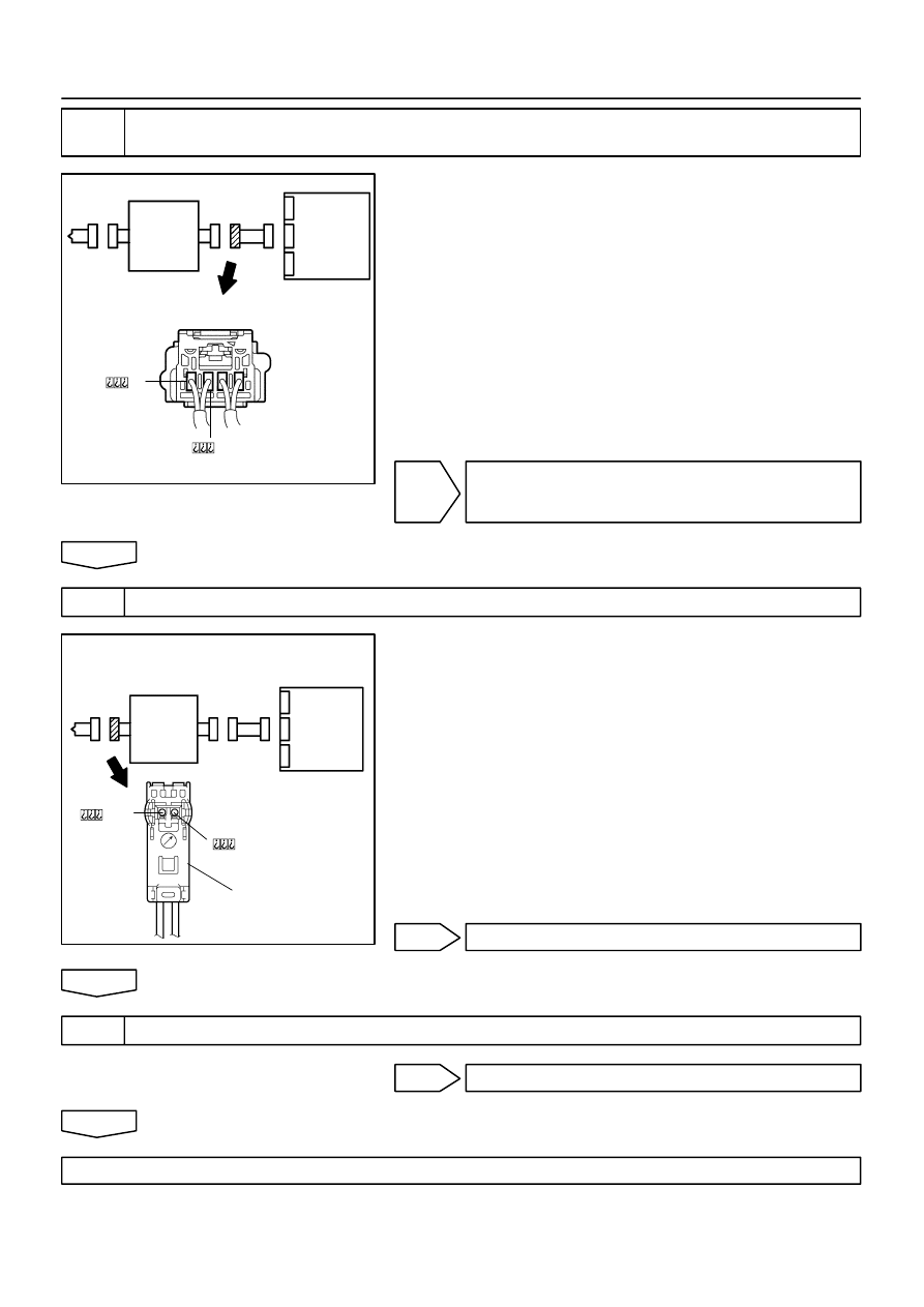
H01004
H41424
H41478
D Squib
Airbag
Sensor
Assy
Center
Spiral
Cable
Sub–Assy
H01000
C89244
H41479
D Squib
Airbag
Sensor
Assy
Center
Spiral
Cable
Sub–Assy
Color: Black
–
DIAGNOSTICS
SUPPLEMENTAL RESTRAINT SYSTEM (April, 2003)
05–569
734
Author:
Date:
2004 COROLLA (RM1037U)
5
CHECK INSTRUMENT PANEL WIRE(AIRBAG SENSOR ASSY CENTER – SPIRAL
CABLE SUB–ASSY)
(a)
Turn the ignition switch to LOCK.
(b)
Disconnect the connector of the instrument panel wire.
(c)
Turn the ignition switch to ON.
(d)
For the connector (on the spiral cable sub–assy side) be-
tween the horn button assy and the spiral cable sub–assy,
measure the voltage between D2+ and body ground.
OK:
Voltage: Below 1 V
NG
REPAIR OR REPLACE INSTRUMENT PANEL
WIRE(AIRBAG SENSOR ASSY CENTER – SPI-
RAL CABLE SUB–ASSY)
OK
6
CHECK SPIRAL CABLE SUB–ASSY
(a)
For the black connector (on the spiral cable sub–assy
side) between the horn button assy and the spiral cable
sub–assy, measure the voltage between D2+ and body
ground.
OK:
Voltage: Below 1 V
NG
REPLACE SPIRAL CABLE SUB–ASSY
OK
7
USE SIMULATION METHOD TO CHECK
NG
Go to step 1
OK
REPLACE ALL SRS COMPONENTS INCLUDING THE WIRE HARNESS
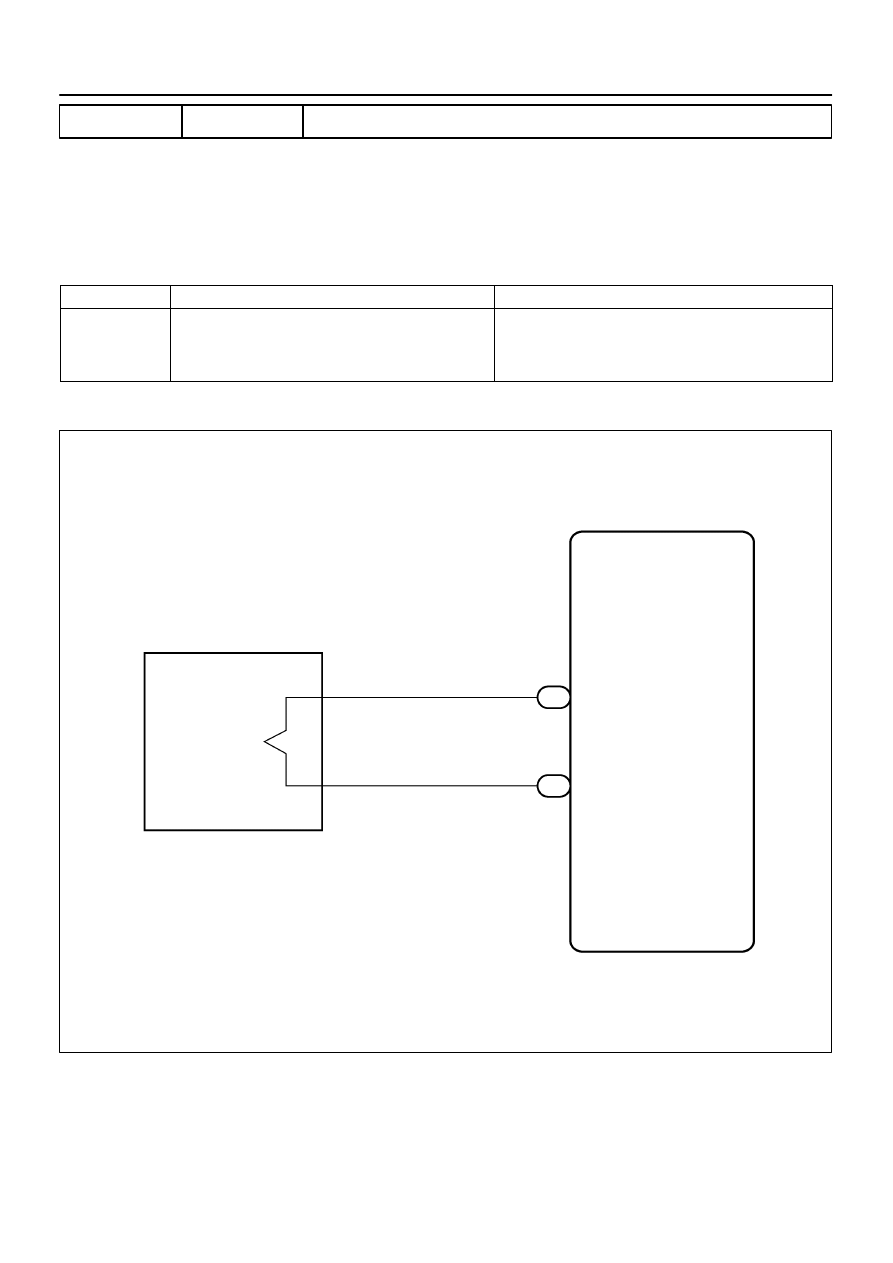
H01454
A15
P Squib (2nd step)
Airbag Sensor Assy Center
Y–GR
Y–P
3
4
8
P2+
A13
P2–
7
A13
P+
P–
05–570
–
DIAGNOSTICS
SUPPLEMENTAL RESTRAINT SYSTEM (April, 2003)
735
Author:
Date:
2004 COROLLA (RM1037U)
DTC
B1185/57 SHORT IN P SQUIB (2ND STEP) CIRCUIT
CIRCUIT DESCRIPTION
The P squib (2nd step) circuit consists of the airbag sensor assy center and instrument panel passenger
airbag assy.
It causes the SRS to deploy when the SRS deployment conditions are satisfied.
DTC B1185/57 is recorded when a short is detected in the P squib (2nd step) circuit.
DTC No.
DTC Detecting Condition
Trouble Area
B1185/57
Short circuit between P2+ wire harness and P2– wire
harness of squib.
P squib (2nd step) malfunction
Airbag sensor assy center malfunction
Instrument panel passenger airbag assy (P squib, 2nd step)
Airbag sensor assy center
Instrument panel wire
WIRING DIAGRAM
055ZP–04
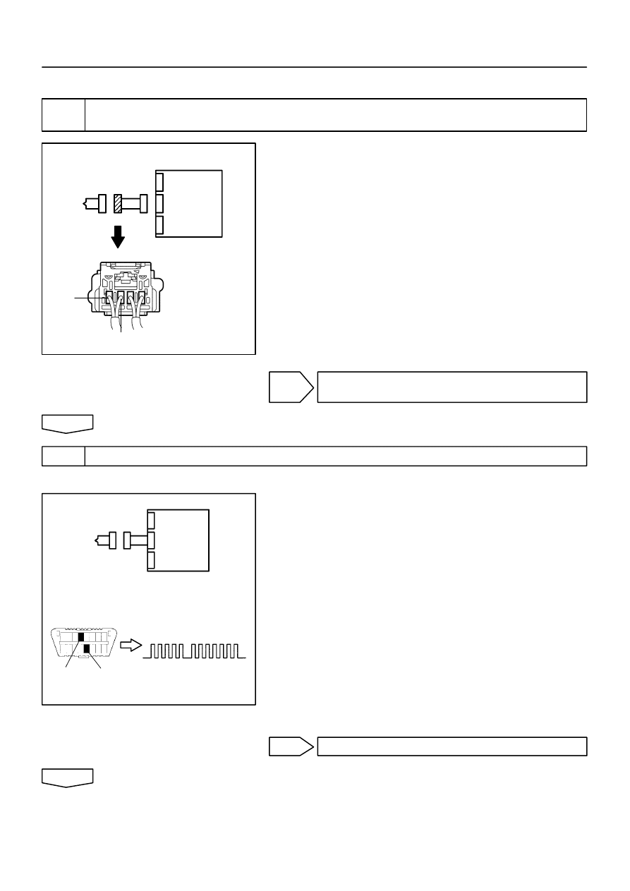
R14286
H41424
H41932
P Squib
Airbag
Sensor
Assy
Center
P2+
P2–
H01023
H10600 H16840
H41979
P Squib
Airbag
Sensor
Assy
Center
DTC B1185/57
DLC3
CG
Tc
–
DIAGNOSTICS
SUPPLEMENTAL RESTRAINT SYSTEM (April, 2003)
05–571
736
Author:
Date:
2004 COROLLA (RM1037U)
INSPECTION PROCEDURE
1
CHECK P SQUIB CIRCUIT(AIRBAG SENSOR ASSY CENTER – INSTRUMENT
PANEL PASSENGER AIRBAG ASSY)
(a)
Disconnect the negative (–) terminal cable from the bat-
tery, and wait at least for 90 seconds.
(b)
Disconnect the connectors between the airbag sensor
assy center and the instrument panel passenger airbag
assy.
(c)
Release the airbag activation prevention mechanism of
the connector (on the airbag sensor assy center side) be-
tween the airbag sensor assy center and the instrument
panel passenger airbag assy (See page
05–424
).
(d)
For the connector (on the instrument panel passenger air-
bag assy side) between the airbag sensor assy center
and the instrument panel passenger airbag assy, mea-
sure the resistance between P2+ and P2–.
OK:
Resistance: 1 M
Ω
or Higher
NG
REPAIR OR REPLACE INSTRUMENT PANEL
WIRE
OK
2
CHECK AIR BAG SENSOR ASSY CENTER
SST
09843–18040
(a)
Connect the connector to the airbag sensor assy center.
(b)
Connect the negative (–) terminal cable to the battery,
and wait at least for 2 seconds.
(c)
Turn the ignition switch to ON, and wait at least for 20 se-
conds.
(d)
Clear the DTC stored in memory (See page
05–424
).
(e)
Turn the ignition switch to LOCK, and wait at least for 20
seconds.
(f)
Turn the ignition switch to ON, and wait at least for 20 se-
conds.
(g)
Check the DTC (See page
05–424
).
OK:
DTC B1185/57 is not output.
HINT:
Codes other than code B1185/57 may be output at this time, but
they are not relevant to this check.
NG
REPLACE AIR BAG SENSOR ASSY CENTER
OK
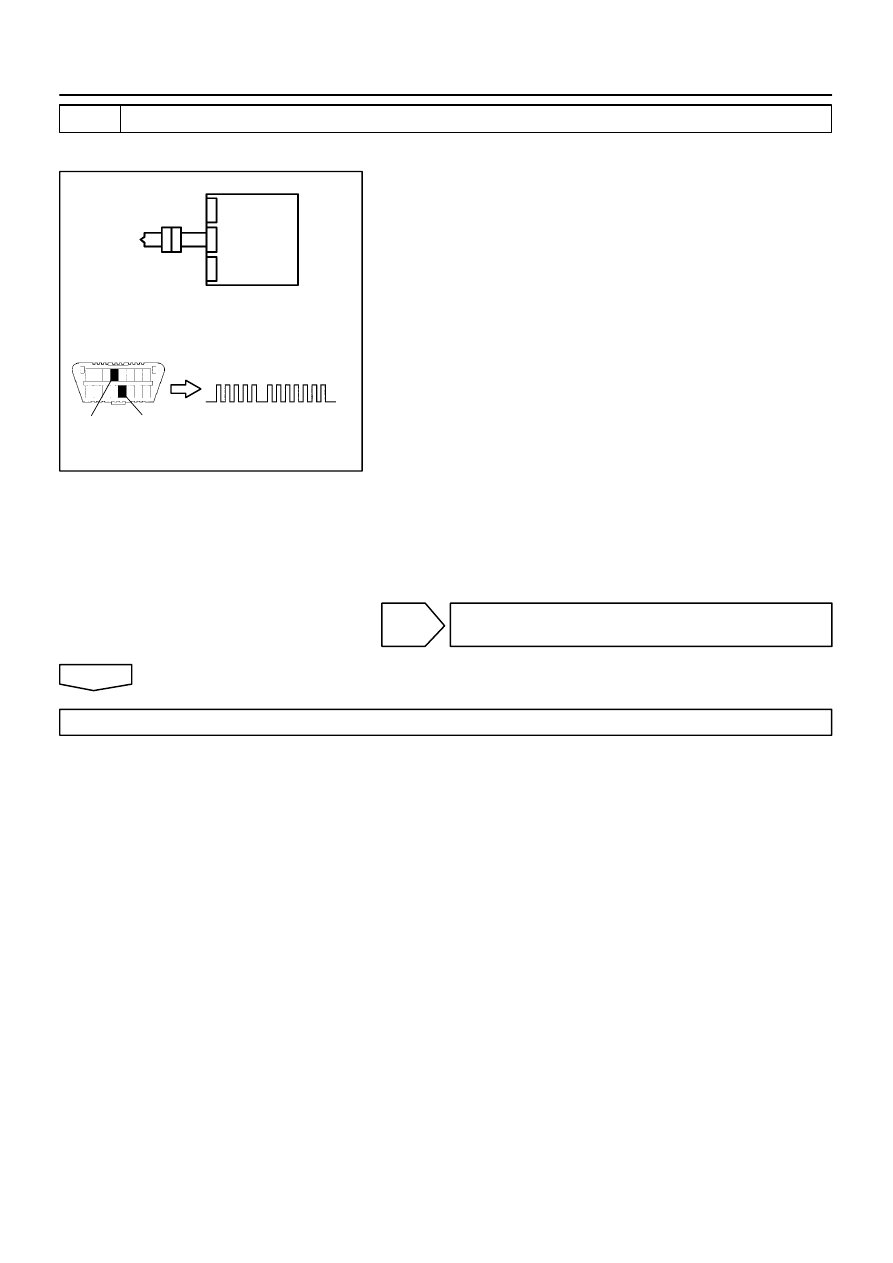
H10600
H01024
H16840
H41980
P Squib
Airbag
Sensor
Assy
Center
DTC B1185/57
DLC3
CG
Tc
05–572
–
DIAGNOSTICS
SUPPLEMENTAL RESTRAINT SYSTEM (April, 2003)
737
Author:
Date:
2004 COROLLA (RM1037U)
3
CHECK P SQUIB
SST
09843–18040
(a)
Turn the ignition switch to LOCK.
(b)
Disconnect the negative (–) terminal cable from the bat-
tery, and wait at least for 90 seconds.
(c)
Connect the instrument panel passenger airbag assy
connector.
(d)
Connect the negative (–) terminal cable to the battery,
and wait at least for 2 seconds.
(e)
Turn the ignition switch to ON, and wait at least for 20 se-
conds.
(f)
Clear the DTC stored in memory (See page
05–424
).
(g)
Turn the ignition switch to LOCK, and wait at least for 20
seconds.
(h)
Turn the ignition switch to ON, and wait at least for 20 se-
conds.
(i)
Check the DTC (See page
05–424
).
OK:
DTC B1185/57 is not output.
HINT:
Codes other than code B1185/57 may be output at this time, but
they are not relevant to this check.
NG
REPLACE INSTRUMENT PANEL PASSENGER
AIR BAG ASSY
OK
USE SIMULATION METHOD TO CHECK

R14286
H41424
H41932
P Squib
Airbag
Sensor
Assy
Center
P2+
P2–
–
DIAGNOSTICS
SUPPLEMENTAL RESTRAINT SYSTEM (April, 2003)
05–573
738
Author:
Date:
2004 COROLLA (RM1037U)
DTC
B1186/58 OPEN IN P SQUIB (2ND STEP) CIRCUIT
CIRCUIT DESCRIPTION
The P squib (2nd step) circuit consists of the airbag sensor assy center and instrument panel passenger
airbag assy.
It causes the SRS to deploy when the SRS deployment conditions are satisfied.
DTC B1186/58 is recorded when an open is detected in the P squib circuit.
DTC No.
DTC Detecting Condition
Trouble Area
B1186/58
Open circuit in P2+ wire harness or P2– wire harness of
squib (2nd step)
P squib (2nd step) malfunction
Airbag sensor assy center malfunction
Instrument panel passenger airbag assy (P squib, 2nd step)
Airbag sensor assy center
Instrument panel wire
WIRING DIAGRAM
See page
05–570
.
INSPECTION PROCEDURE
1
CHECK P SQUIB CIRCUIT(AIRBAG SENSOR ASSY CENTER – INSTRUMENT
PANEL PASSENGER AIRBAG ASSY)
(a)
Disconnect the negative (–) terminal cable from the bat-
tery, and wait at least for 90 seconds.
(b)
Disconnect the connectors between the airbag sensor
assy center and the instrument panel passenger airbag
assy.
(c)
For the connector (on the instrument panel passenger air-
bag assy side) between the airbag sensor assy center
and the instrument panel passenger airbag assy, mea-
sure the resistance between P2+ and P2–.
OK:
Resistance: Below 1
Ω
NG
REPAIR OR REPLACE INSTRUMENT PANEL
WIRE
OK
055ZQ–04
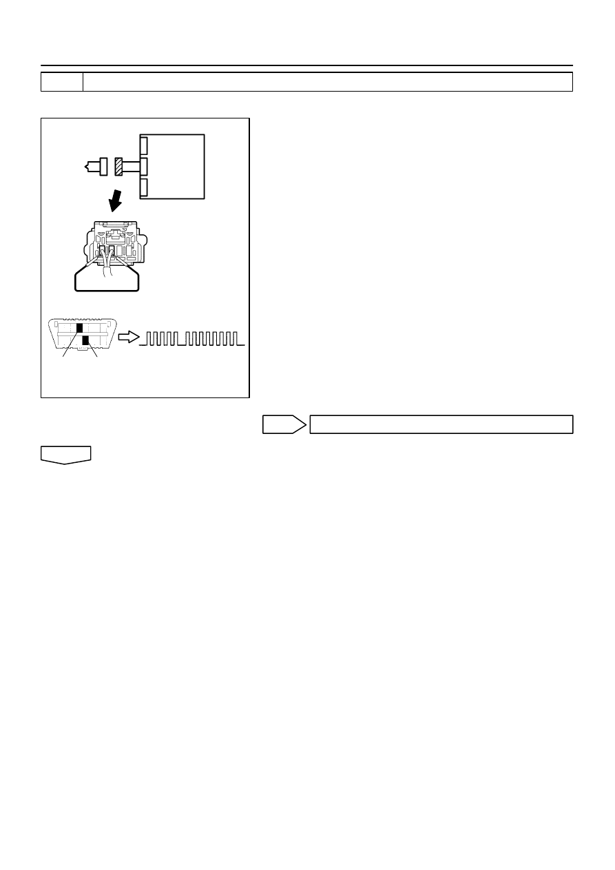
H01023
H10600 H16841
H16853
H41981
P Squib
Airbag
Sensor
Assy
Center
DTC B1186/58
DLC3
CG
Tc
05–574
–
DIAGNOSTICS
SUPPLEMENTAL RESTRAINT SYSTEM (April, 2003)
739
Author:
Date:
2004 COROLLA (RM1037U)
2
CHECK AIR BAG SENSOR ASSY CENTER
SST
09843–18040
(a)
Connect the connector to the airbag sensor assy center.
(b)
Using a service wire, connect P2+ and P2– of the connec-
tor (on the instrument panel passenger airbag assy side)
between the airbag sensor assy center and the instru-
ment panel passenger airbag assy.
(c)
Connect the negative (–) terminal cable to the battery,
and wait at least for 2 seconds.
(d)
Turn the ignition switch to ON, and wait at least for 20 se-
conds.
(e)
Clear the DTC stored in memory (See page
05–424
).
(f)
Turn the ignition switch to LOCK, and wait at least for 20
seconds.
(g)
Turn the ignition switch to ON, and wait at least for 20 se-
conds.
(h)
Check the DTC (See page
05–424
).
OK:
DTC B1186/58 is not output.
HINT:
Codes other than code B1186/58 may be output at this time, but
they are not relevant to this check.
NG
REPLACE AIR BAG SENSOR ASSY CENTER
OK

H10600
H01024
H16841
H41982
Airbag
Sensor
Assy
Center
P Squib
DTC B1186/58
DLC3
CG
Tc
–
DIAGNOSTICS
SUPPLEMENTAL RESTRAINT SYSTEM (April, 2003)
05–575
740
Author:
Date:
2004 COROLLA (RM1037U)
3
CHECK P SQUIB
SST
09843–18040
(a)
Turn the ignition switch to LOCK.
(b)
Disconnect the negative (–) terminal cable from the bat-
tery, and wait at least for 90 seconds.
(c)
Connect the instrument panel passenger airbag assy
connector.
(d)
Connect the negative (–) terminal cable to the battery,
and wait at least for 2 seconds.
(e)
Turn the ignition switch to ON, and wait at least for 20 se-
conds.
(f)
Clear the DTC stored in memory (See page
05–424
).
(g)
Turn the ignition switch to LOCK, and wait at least for 20
seconds.
(h)
Turn the ignition switch to ON, and wait at least for 20 se-
conds.
(i)
Check the DTC (See page
05–424
).
OK:
DTC B1186/58 is not output.
HINT:
Codes other than code B1186/58 may be output at this time, but
they are not relevant to this check.
NG
REPLACE INSTRUMENT PANEL PASSENGER
AIR BAG ASSY
OK
USE SIMULATION METHOD TO CHECK
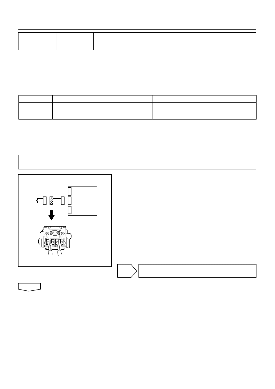
R14286
H41424
H41932
P Squib
Airbag
Sensor
Assy
Center
P2+
P2–
05–576
–
DIAGNOSTICS
SUPPLEMENTAL RESTRAINT SYSTEM (April, 2003)
741
Author:
Date:
2004 COROLLA (RM1037U)
DTC
B1187/55 SHORT IN P SQUIB (2ND STEP) CIRCUIT
(TO GROUND)
CIRCUIT DESCRIPTION
The P squib (2nd step) circuit consists of the airbag sensor assy center and instrument panel passenger
airbag assy.
It causes the SRS to deploy when the SRS deployment conditions are satisfied.
DTC B1187/55 is recorded when ground short is detected in the P squib (2nd step) circuit.
DTC No.
DTC Detecting Condition
Trouble Area
B1187/55
Short circuit in P squib (2nd step) wire harness (to ground)
P squib malfunction
Airbag sensor assy center malfunction
Instrument panel passenger airbag assy (P squib, 2nd step)
Airbag sensor assy center
Instrument panel wire
WIRING DIAGRAM
See page
05–570
.
INSPECTION PROCEDURE
1
CHECK P SQUIB CIRCUIT(AIRBAG SENSOR ASSY CENTER – INSTRUMENT
PANEL PASSENGER AIRBAG ASSY)
(a)
Disconnect the negative (–) terminal cable from the bat-
tery, and wait at least for 90 seconds.
(b)
Disconnect the connector between the airbag sensor
assy center and the instrument panel passenger airbag
assy.
(c)
For the connector (on the instrument panel passenger air-
bag assy side) between the airbag sensor assy center
and the instrument panel passenger airbag assy, mea-
sure the resistance between P2+ and body ground.
OK:
Resistance: 1 M
Ω
or Higher
NG
REPAIR OR REPLACE INSTRUMENT PANEL
WIRE
OK
055ZR–04
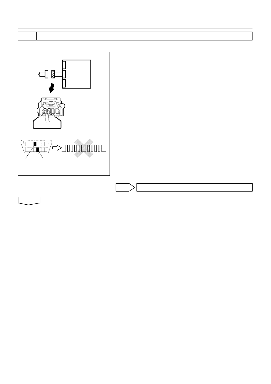
H01023
H10600 H16838
H16853
H41983
P Squib
Airbag
Sensor
Assy
Center
DTC B1187/55
DLC3
CG
Tc
–
DIAGNOSTICS
SUPPLEMENTAL RESTRAINT SYSTEM (April, 2003)
05–577
742
Author:
Date:
2004 COROLLA (RM1037U)
2
CHECK AIR BAG SENSOR ASSY CENTER
SST
09843–18040
(a)
Connect the connector to the airbag sensor assy center.
(b)
Using a service wire, connect P2+ and P2– of the connec-
tor (on the instrument panel passenger airbag assy side)
between the airbag sensor assy center and the instru-
ment panel passenger airbag assy.
(c)
Connect the negative (–) terminal cable to the battery,
and wait at least for 2 seconds.
(d)
Turn the ignition switch to ON, and wait at least for 20 se-
conds.
(e)
Clear the DTC stored in memory (See page
05–424
).
(f)
Turn the ignition switch to LOCK, and wait at least for 20
seconds.
(g)
Turn the ignition switch to ON, and wait at least for 20 se-
conds.
(h)
Check the DTC (See page
05–424
).
OK:
DTC B1187/55 is not output.
HINT:
Codes other than code B1187/55 may be output at this time, but
they are not relevant to this check.
NG
REPLACE AIR BAG SENSOR ASSY CENTER
OK
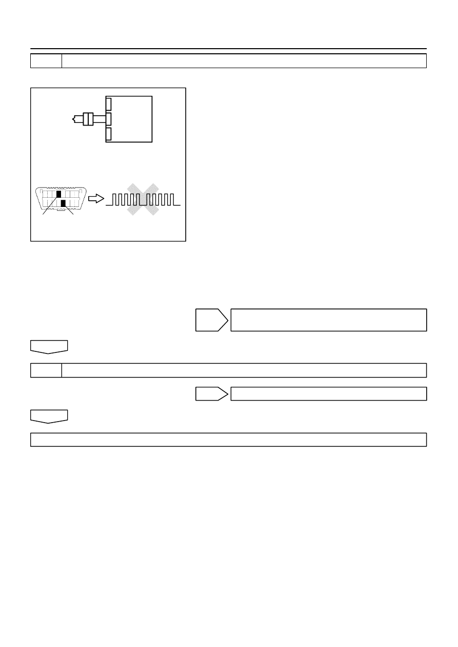
H10600
H01024
H16838
H41984
P Squib
Airbag
Sensor
Assy
Center
DTC B1187/55
DLC3
CG
Tc
05–578
–
DIAGNOSTICS
SUPPLEMENTAL RESTRAINT SYSTEM (April, 2003)
743
Author:
Date:
2004 COROLLA (RM1037U)
3
CHECK P SQUIB
SST
09843–18040
(a)
Turn the ignition switch to LOCK.
(b)
Disconnect the negative (–) terminal cable from the bat-
tery, and wait at least for 90 seconds.
(c)
Connect the instrument panel passenger airbag assy
connector.
(d)
Connect the negative (–) terminal cable to the battery,
and wait at least for 2 seconds.
(e)
Turn the ignition switch to ON, and wait at least for 20 se-
conds.
(f)
Clear the DTC stored in memory (See page
05–424
).
(g)
Turn the ignition switch to LOCK, and wait at least for 20
seconds.
(h)
Turn the ignition switch to ON, and wait at least for 20 se-
conds.
(i)
Check the DTC (See page
05–424
).
OK:
DTC B1187/55 is not output.
HINT:
Codes other than code B1187/55 may be output at this time, but
they are not relevant to this check.
NG
REPLACE INSTRUMENT PANEL PASSENGER
AIR BAG ASSY
OK
4
USE SIMULATION METHOD TO CHECK
NG
Go to step 1
OK
REPLACE ALL SRS COMPONENTS INCLUDING THE WIRE HARNESS
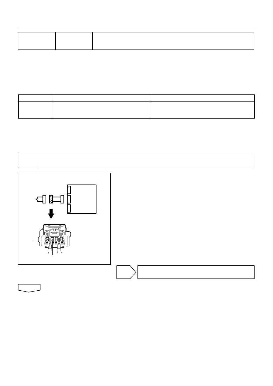
R14286
H41424
H41932
P Squib
Airbag
Sensor
Assy
Center
P2+
P2–
–
DIAGNOSTICS
SUPPLEMENTAL RESTRAINT SYSTEM (April, 2003)
05–579
744
Author:
Date:
2004 COROLLA (RM1037U)
DTC
B1188/56 SHORT IN SQUIB (2ND STEP) CIRCUIT (TO
B+)
CIRCUIT DESCRIPTION
The P squib (2nd step) circuit consists of the airbag sensor assy center and instrument panel passenger
airbag assy.
It causes the SRS to deploy when the SRS deployment conditions are satisfied.
DTC B1188/56 is recorded when a B+ short is detected in the P squib (2nd step) circuit.
DTC No.
DTC Detecting Condition
Trouble Area
B1188/56
Short circuit in P squib (2nd step) wire harness (to B+)
P squib (2nd step) malfunction
Airbag sensor assy center malfunction
Instrument panel passenger airbag assy (P squib, 2nd step)
Airbag sensor assy center
Instrument panel wire
WIRING DIAGRAM
See page
05–570
.
INSPECTION PROCEDURE
1
CHECK P SQUIB CIRCUIT(AIRBAG SENSOR ASSY CENTER – INSTRUMENT
PANEL PASSENGER AIRBAG ASSY)
(a)
Disconnect the negative (–) terminal cable from the bat-
tery, and wait at least for 90 seconds.
(b)
Disconnect the connector between the airbag sensor
assy center and the instrument panel passenger airbag
assy.
(c)
Connect the negative (–) terminal cable to the battery,
and wait at least for 2 seconds.
(d)
Turn the ignition switch to ON.
(e)
For the connector (on the instrument panel passenger air-
bag assy side) between the airbag sensor assy center
and the instrument panel passenger airbag assy, mea-
sure the voltage between P2+ and body ground.
OK:
Voltage: Below 1 V
NG
REPAIR OR REPLACE INSTRUMENT PANEL
WIRE
OK
055ZS–04
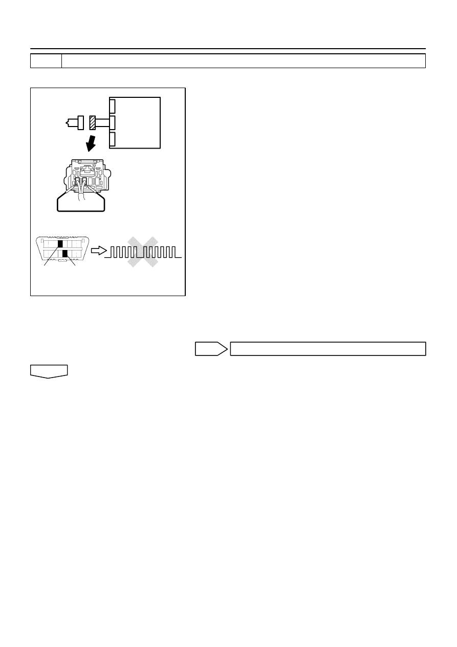
H01023
H10600 H16839
H16853
H41985
P Squib
Airbag
Sensor
Assy
Center
DTC B1188/56
DLC3
CG
Tc
05–580
–
DIAGNOSTICS
SUPPLEMENTAL RESTRAINT SYSTEM (April, 2003)
745
Author:
Date:
2004 COROLLA (RM1037U)
2
CHECK AIR BAG SENSOR ASSY CENTER
SST
09843–18040
(a)
Turn the ignition switch to LOCK.
(b)
Disconnect the negative (–) terminal cable from the bat-
tery, and wait at least for 90 seconds.
(c)
Connect the connector to the airbag sensor assy center.
(d)
Using a service wire, connect P2+ and P2– of the connec-
tor (on the instrument panel passenger airbag assy side)
between the airbag sensor assy center and the instru-
ment panel passenger airbag assy.
(e)
Connect the negative (–) terminal cable to the battery,
and wait at least for 2 seconds.
(f)
Turn the ignition switch to ON, and wait at least for 20 se-
conds.
(g)
Clear the DTC stored in memory (See page
05–424
).
(h)
Turn the ignition switch to LOCK, and wait at least for 20
seconds.
(i)
Turn the ignition switch to ON, and wait at least for 20 se-
conds.
(j)
Check the DTC (See page
05–424
).
OK:
DTC B1188/56 is not output.
HINT:
Codes other than code B1188/56 may be output at this time, but
they are not relevant to this check.
NG
REPLACE AIR BAG SENSOR ASSY CENTER
OK
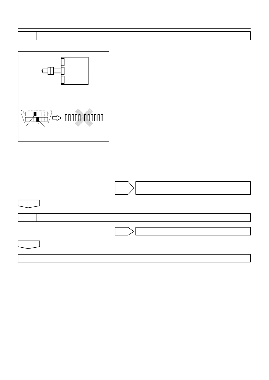
H10600
H01024
H16839
H41986
P Squib
Airbag
Sensor
Assy
Center
DTC B1188/56
DLC3
CG
Tc
–
DIAGNOSTICS
SUPPLEMENTAL RESTRAINT SYSTEM (April, 2003)
05–581
746
Author:
Date:
2004 COROLLA (RM1037U)
3
CHECK P SQUIB
SST
09843–18040
(a)
Turn the ignition switch to LOCK.
(b)
Disconnect the negative (–) terminal cable from the bat-
tery, and wait at least for 90 seconds.
(c)
Connect the instrument panel passenger airbag assy
connector.
(d)
Connect the negative (–) terminal cable to the battery,
and wait at least for 2 seconds.
(e)
Turn the ignition switch to ON, and wait at least for 20 se-
conds.
(f)
Clear the DTC stored in memory (See page
05–424
).
(g)
Turn the ignition switch to LOCK, and wait at least for 20
seconds.
(h)
Turn the ignition switch to ON, and wait at least for 20 se-
conds.
(i)
Check the DTC (See page
05–424
).
OK:
DTC B1188/56 is not output.
HINT:
Codes other than code B1188/56 may be output at this time, but
they are not relevant to this check.
NG
REPLACE INSTRUMENT PANEL PASSENGER
AIR BAG ASSY
OK
4
USE SIMULATION METHOD TO CHECK
NG
Go to step 1
OK
REPLACE ALL SRS COMPONENTS INCLUDING THE WIRE HARNESS
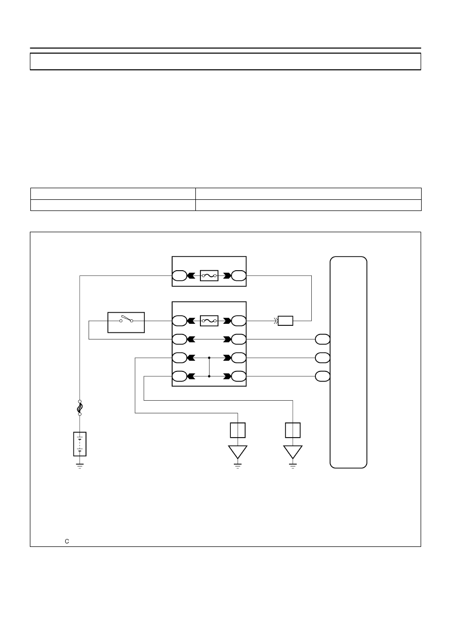
H42004
Engine Room R/B and J/B
Airbag Sensor Assy Center
B
B–R
1A
1
1
2
MAIN
Instrument Panel J/B
B–R
2
IA4
IM
IM
IL
II
IF
II
IH
II
6
3
5
8
4
3
10
10
B–W
B–W
B
W–B
W–B
W–B
W–B
W–B
W–B
B–O
AM–2
AM2
IG2
A13
A13
A13
5
27
28
IG2
E1
E2
FL MAIN
Battery
I10
Ignition SW
6
5
J6
J/C
J7
J/C
A
A
IE
IG
1
05–582
–
DIAGNOSTICS
SUPPLEMENTAL RESTRAINT SYSTEM (April, 2003)
747
Author:
Date:
2004 COROLLA (RM1037U)
SOURCE VOLTAGE DROP
CIRCUIT DESCRIPTION
The SRS is equipped with a voltage–increase circuit (DC–DC converter) in the airbag sensor assy center
in case the source voltage drops.
When the battery voltage drops, the voltage–increase circuit (DC–DC converter) functions to increase the
voltage of the SRS to normal voltage.
The diagnosis system malfunction display for this circuit is different from other circuits that is when the SRS
warning light remains lit up and the DTC is a normal code, source voltage drop is indicated.
Malfunction in this circuit is not recorded in the airbag sensor assy center, and the source voltage returns
to normal, the SRS warning light automatically goes off.
DTC No.
Diagnosis
(Normal)
Source voltage drop
WIRING DIAGRAM
055ZT–07
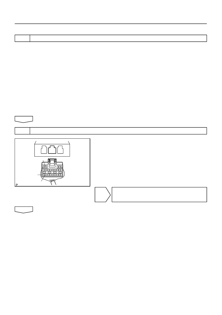
H40065
IG2
E2
E1
–
DIAGNOSTICS
SUPPLEMENTAL RESTRAINT SYSTEM (April, 2003)
05–583
748
Author:
Date:
2004 COROLLA (RM1037U)
INSPECTION PROCEDURE
1
PREPARE FOR INSPECTION
(a)
Disconnect the negative (–) terminal cable from the battery, and wait at least for 90 seconds.
(b)
Remove the horn button assy (See page
60–13
).
(c)
Disconnect the connector of the instrument panel passenger airbag assy (See page
60–26
).
(d)
Disconnect the connector of the front seat airbag assy RH and LH (See page
60–32
).
(e)
Disconnect the connector of the seat belt pretensioner RH and LH (See page
61–9
).
(f)
Disconnect the connectors of the airbag sensor assy center (See page
60–38
).
(g)
Disconnect the connector of the airbag front RH sensor and airbag sensor front LH (See page
60–40
and
60–42
).
(h)
Disconnect the connector of the side airbag sensor assy RH and LH (See page
60–44
).
(i)
Disconnect the connector of the seat position airbag sensor (See page
60–46
).
CAUTION:
Store the horn button assy, instrument panel passenger airbag assy and front seat airbag assy with
the front surface facing upward.
2
CHECK SOURCE VOLTAGE
(a)
Connect the negative (–) terminal cable to the battery,
and wait at least for 2 seconds.
(b)
Turn the ignition switch to ON, and wait at least for 60 se-
conds.
(c)
Measure the voltage between E1 (E2) and terminal IG2
on the sensor and operate electric system (defogger, wip-
er, headlight, heater blower, etc.).
OK:
Voltage: 10 – 14 V
NG
REPAIR OR REPLACE HARNESS BETWEEN
BATTERY AND AIRBAG SENSOR ASSY
CENTER,AND CHARGING SYSTEM
OK
05–584
–
DIAGNOSTICS
SUPPLEMENTAL RESTRAINT SYSTEM (April, 2003)
749
Author:
Date:
2004 COROLLA (RM1037U)
3
CHECK SRS WARNING LIGHT TURN OFF
(a)
Turn the ignition switch to LOCK.
(b)
Disconnect the negative (–) terminal cable from the battery, and wait at least for 90 seconds.
(c)
Connect the horn button assy connectors.
(d)
Connect the instrument panel passenger airbag assy connector.
(e)
Connect the front seat airbag assy RH and LH connectors.
(f)
Connect the seat belt pretensioner RH and LH connectors.
(g)
Connect the airbag sensor assy center connectors.
(h)
Connect the front airbag sensor RH and LH connectors.
(i)
Connect the side airbag sensor assy RH and LH connectors.
(j)
Connect the seat position airbag sensor connector.
(k)
Connect the negative (–) terminal cable to the battery.
(l)
Turn the ignition switch to ON, and wait at least for 60 seconds.
(m)
Operate electric system (defogger, wiper headlight, heater blower, etc.) and check that SRS warning
light goes off.
OK:
SRS warning light is not light up.
NG
REPAIR OR REPLACE HARNESS BETWEEN
BATTERY AND AIRBAG SENSOR ASSY
CENTER,AND CHARGING SYSTEM
OK
4
CHECK AIR BAG SENSOR ASSY CENTER
SST
09843–18040
(a)
Turn the ignition switch to LOCK.
(b)
Disconnect the negative (–) terminal cable from the battery, and wait at least for 90 seconds.
(c)
Connect the negative (–) terminal cable to the battery, and wait at least for 2 seconds.
(d)
Turn the ignition switch to ON, and wait at least for 20 seconds.
(e)
Clear the DTC stored in memory (See page
05–424
).
(f)
Turn the ignition switch to LOCK, and wait at least for 20 seconds.
(g)
Turn the ignition switch to ON, and wait at least for 20 seconds.
(h)
Check the DTC (See page
05–424
).
OK:
DTC is not output.
NG
REPLACE AIR BAG SENSOR ASSY CENTER
OK
USE SIMULATION METHOD TO CHECK
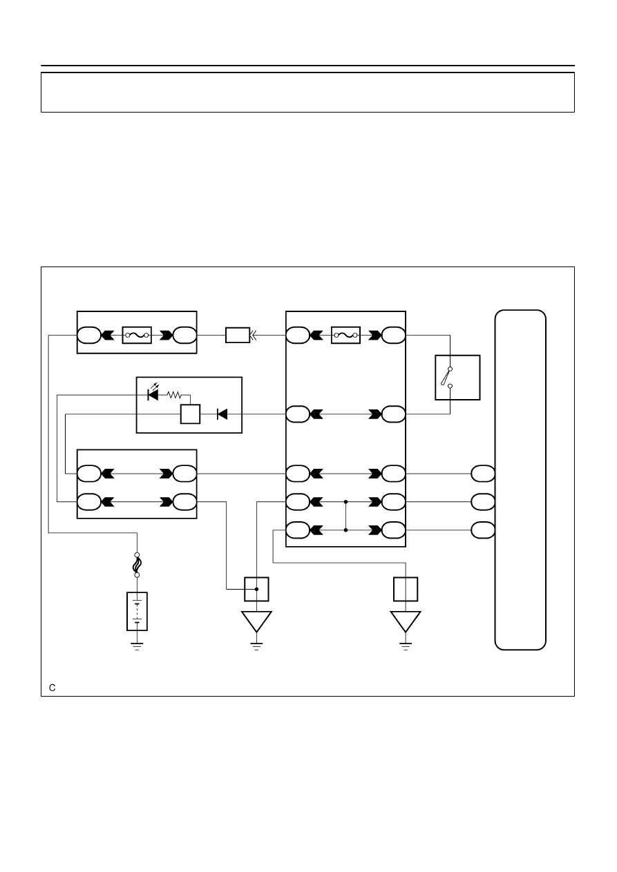
H42005
Instrument Panel J/B
LA
A13
3
B–Y
W–B
5
E1
1
27
Engine Room R/B and J/B
IA4
B
I10
Ignition SW
6
FL MAIN
Battery
E2
28
W–B
2
2
II
B
IH
14
1A
3
A13
A13
4C
B–R
B
39
8
5
4
B–Y
1
W–B
Airbag Sensor Assy Center
II
II
MAIN
B–R
4C
4B
4B
15
18
21
IJ
IF
IK
IM
IM
IL
AM2
AM2
IG2
W–B
3
B–O
B–Y
W–B
32
5
1
10
10
A
A
A
IE
IG
J6
J/C
J7
J/C
B–W
6
W–B
SRS
C9
Combination Meter
1
2
Center J/B
–
DIAGNOSTICS
SUPPLEMENTAL RESTRAINT SYSTEM (April, 2003)
05–585
750
Author:
Date:
2004 COROLLA (RM1037U)
SRS WARNING LIGHT CIRCUIT MALFUNCTION (ALWAYS LIGHT
UP, WHEN DTC IS NOT OUTPUT)
CIRCUIT DESCRIPTION
The SRS warning light is located on the combination meter.
When the SRS is normal, the SRS warning light lights up for approx. 6 seconds after the ignition switch is
turned from the LOCK position to ON position, and then turns off automatically.
If there is a malfunction in the SRS, the SRS warning light lights up to inform the driver of the abnormality.
When terminals Tc and CG of the DLC3 are connected, the DTC is displayed by blinking the SRS warning
light.
WIRING DIAGRAM
055ZU–05
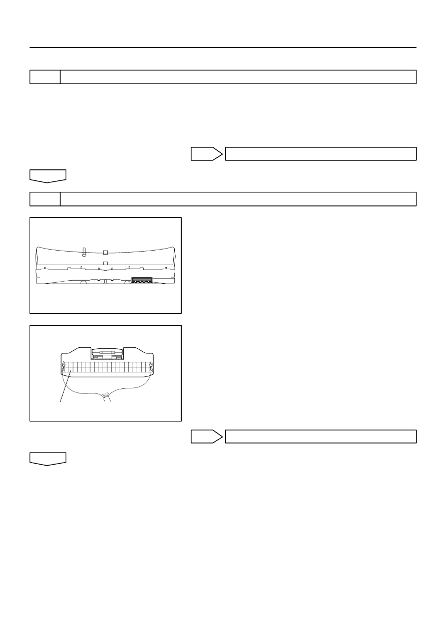
H42000
H41993
SW
05–586
–
DIAGNOSTICS
SUPPLEMENTAL RESTRAINT SYSTEM (April, 2003)
751
Author:
Date:
2004 COROLLA (RM1037U)
INSPECTION PROCEDURE
1
CHECK CONNECTOR
(a)
Disconnect the negative (–) terminal cable from the battery, and wait at least for 90 seconds.
(b)
Check the connection of the combination meter connector and the airbag sensor assy center connec-
tors.
OK:
The connectors are connected.
NG
CONNECT CONNECTORS
OK
2
CHECK COMBINATION METER ASSY
(a)
Disconnect the connector from the combination meter.
(b)
Connect the negative (–) terminal cable to the battery,
and wait at least for 2 seconds.
(c)
Turn the ignition switch to ON, and wait at least for 6 se-
conds.
(d)
Measure the voltage between SW and body ground.
OK:
Voltage: Above 8 V
NG
REPLACE COMBINATION METER ASSY
OK
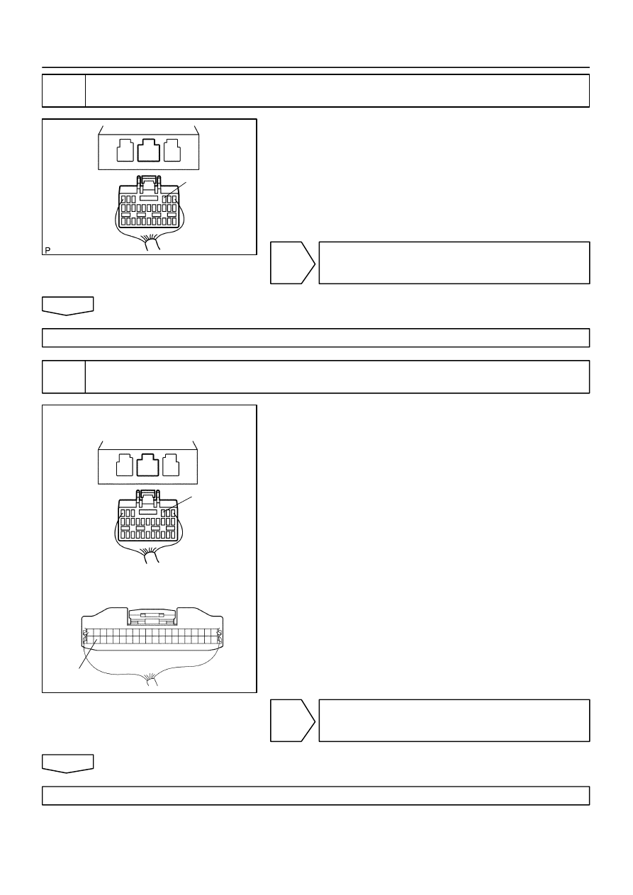
H40065
LA
H41994
Airbag Sensor Assy Center:
Combination Meter:
LA
SW
–
DIAGNOSTICS
SUPPLEMENTAL RESTRAINT SYSTEM (April, 2003)
05–587
752
Author:
Date:
2004 COROLLA (RM1037U)
3
CHECK INSTRUMENT PANEL WIRE(AIRBAG SENSOR ASSY
CENTER–COMBINATION METER ASSY)
(a)
Turn the ignition switch to LOCK.
(b)
Disconnect the negative (–) terminal cable from the bat-
tery, and wait at least for 90 seconds.
(c)
Disconnect the connector from the airbag sensor assy
center.
(d)
Measure the resistance between LA and body ground.
OK:
Resistance: 1M
Ω
or Higher
NG
REPAIR OR REPLACE INSTRUMENT PANEL
WIRE (AIRBAG SENSOR ASSY CENTER – COM-
BINATION METER ASSY)
OK
REPLACE AIR BAG SENSOR ASSY CENTER
4
CHECK INSTRUMENT PANEL WIRE(AIRBAG SENSOR ASSY
CENTER–COMBINATION METER ASSY)
(a)
For the connector (on the airbag sensor assy center side)
between the combination meter and the airbag sensor
assy center, measure the resistance between SW and
LA.
OK:
Resistance: Below 1
Ω
NG
REPAIR OR REPLACE INSTRUMENT PANEL
WIRE (AIRBAG SENSOR ASSY CENTER – COM-
BINATION METER ASSY)
OK
REPLACE AIR BAG SENSOR ASSY CENTER
05–588
–
DIAGNOSTICS
SUPPLEMENTAL RESTRAINT SYSTEM (April, 2003)
753
Author:
Date:
2004 COROLLA (RM1037U)
SRS WARNING LIGHT CIRCUIT MALFUNCTION (DOES NOT LIGHT
UP, WHEN IGNITION SWITCH IS TURNED TO ON)
CIRCUIT DESCRIPTION
The SRS warning light is located on the combination meter.
When the SRS is normal, the SRS warning light lights up for approx. 6 seconds after the ignition switch is
turned from the LOCK position to ON position, and then turns off automatically.
If there is a malfunction is the SRS, the SRS warning light lights up to inform the driver of the abnormality.
When terminals Tc and CG of the DLC3 are connected, the DTC is displayed by blinking the SRS warning
light.
WIRING DIAGRAM
See page
05–585
.
INSPECTION PROCEDURE
1
CHECK SOURCE VOLTAGE
(a)
Measure the voltage of the battery.
OK:
Voltage: 10 – 14 V
NG
REPAIR OR REPLACE HARNESS BETWEEN
BATTERY AND AIRBAG SENSOR ASSY
CENTER,AND CHARGING SYSTEM
OK
2
CHECK AIR BAG SENSOR ASSY CENTER
(a)
Disconnect the negative (–) terminal cable from the battery, and wait at least for 90 seconds.
(b)
Disconnect the connectors from the airbag sensor assy center.
(c)
Connect the negative (–) terminal cable to the battery, and wait at least for 2 seconds.
(d)
Turn the ignition switch to ON.
(e)
Check SRS warning light light up in the combination meter assy.
OK:
Not SRS warning light light up.
NG
REPLACE AIR BAG SENSOR ASSY CENTER
OK
055ZV–04
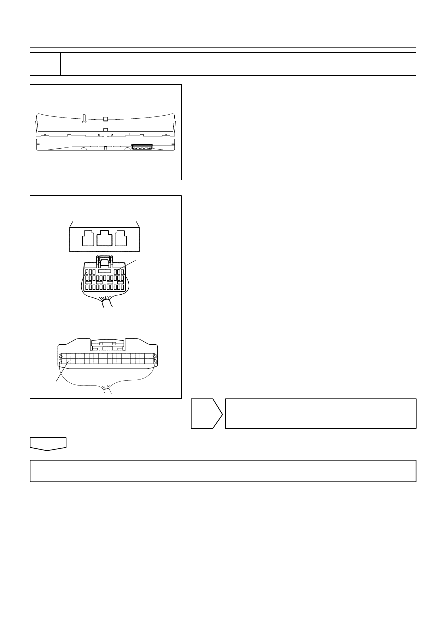
H42000
H41994
Airbag Sensor Assy Center:
Combination Meter:
LA
SW
–
DIAGNOSTICS
SUPPLEMENTAL RESTRAINT SYSTEM (April, 2003)
05–589
754
Author:
Date:
2004 COROLLA (RM1037U)
3
CHECK WIRE HARNESS(COMBINATION METER ASSY – AIRBAG SENSOR ASSY
CENTER)
(a)
Turn the ignition switch to LOCK.
(b)
Disconnect the negative (–) terminal cable from the bat-
tery, and wait at least for 90 seconds.
(c)
Disconnect the connector from the combination meter.
(d)
Connect the negative (–) terminal cable to the battery,
and wait at least for 2 seconds.
(e)
Turn the ignition switch to ON.
(f)
For the connector (on the airbag sensor assy center side)
between the airbag sensor assy center and the combina-
tion meter, measure the voltage between LA and body
ground.
OK:
Voltage: Below 1 V
NG
REPAIR OR REPLACE HARNESS BETWEEN
AIRBAG SENSOR ASSY CENTER AND
COMBINATION METER ASSY
OK
REPAIR OR REPLACE COMBINATION METER ASSY OR WIRE HARNESS BETWEEN
COMBINATION METER ASSY AND BATTERY
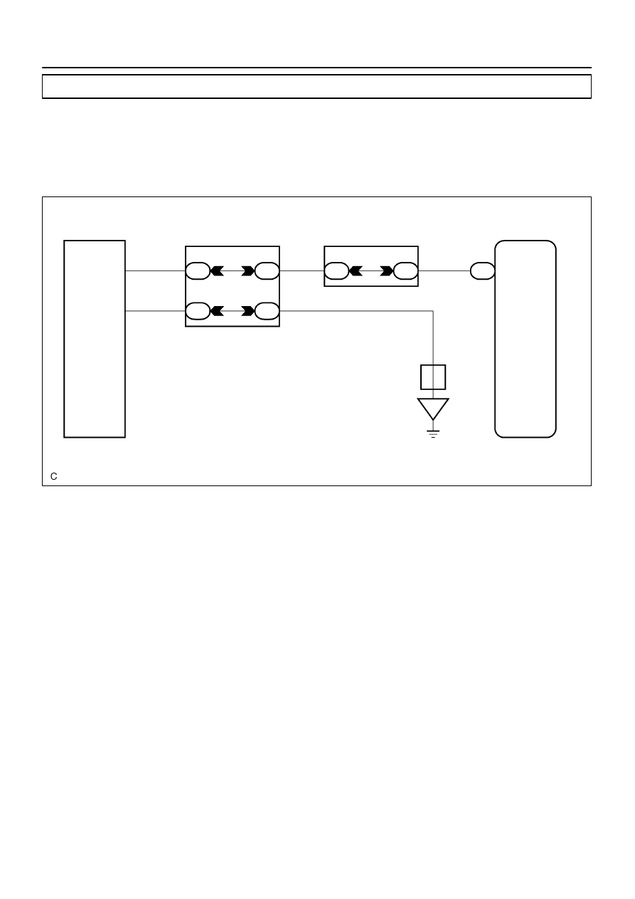
H42006
Airbag Sensor Assy Center
A13 Tc
19
P–B
W–B
II
IJ
1
4
IE
4B
4C
4B
5
3
16
21
P–B
W–B
Tc
CG
13
4
D1
DLC3
Center J/B
Instrument Panel J/B
4C
P–B
A
J6
JC
05–590
–
DIAGNOSTICS
SUPPLEMENTAL RESTRAINT SYSTEM (April, 2003)
755
Author:
Date:
2004 COROLLA (RM1037U)
TC TERMINAL CIRCUIT
CIRCUIT DESCRIPTION
DTC output mode is set by connecting between TC and CG of the DLC3.
The DTCs are displayed by blinking the SRS warning light.
WIRING DIAGRAM
HINT:
When each warning light stays blinking, ground short in the wiring until the terminal TC of the DLC3 or internal
ground short in each ECU is suspected.
055ZW–05
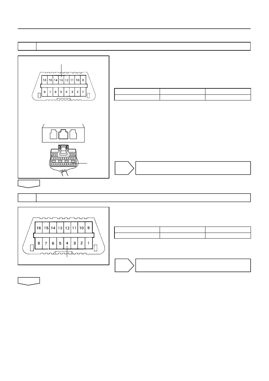
H40065
H40173
H43360
TC
DLC3:
Airbag Sensor Assy Center:
TC
H40173
CG
–
DIAGNOSTICS
SUPPLEMENTAL RESTRAINT SYSTEM (April, 2003)
05–591
756
Author:
Date:
2004 COROLLA (RM1037U)
INSPECTION PROCEDURE
1
CHECK WIRE HARNESS(DLC3 – AIRBAG SENSOR ASSY CENTER)
(a)
Turn the ignition switch to the LOCK position.
(b)
Disconnect the aribag sensor assy center connector.
(c)
Measure the resistance according to the value(s) in the
table below.
Standard:
Tester connection
Condition
Specified condition
TC – TC
Always
Below 1
Ω
NG
REPAIR OR REPLACE WIRE HARNESS(TC of
ELC3 – TC of AIRBAG SENSOR ASSY CENTER)
OK
2
CHECK WIRE HARNESS(CG of DLC3 – BODY GROUND)
(a)
Measure the resistance according to the value(s) in the
table below.
Standard:
Tester connection
Condition
Specified condition
CG – Body ground
Always
Below 1
Ω
NG
REPAIR OR REPLACE WIRE HARNESS(CG of
DLC3 – BODY GROUND)
OK
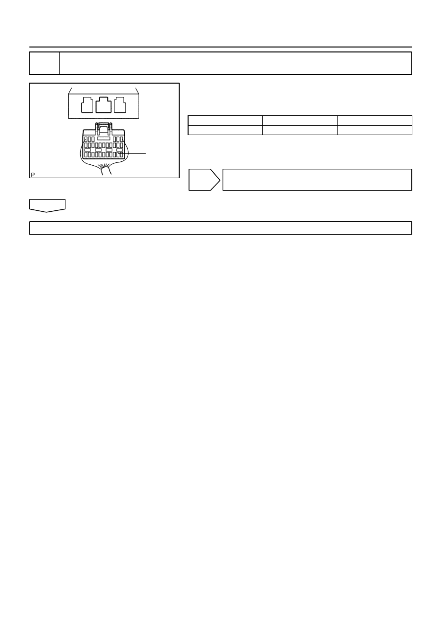
H40065
TC
05–592
–
DIAGNOSTICS
SUPPLEMENTAL RESTRAINT SYSTEM (April, 2003)
757
Author:
Date:
2004 COROLLA (RM1037U)
3
CHECK WIRE HARNESS(TC of AIRBAG SENSOR ASSY CENTER – BODY
GROUND)
(a)
Measure the resistance according to the value(s) in the
table below.
Standard:
Tester connection
Condition
Specified condition
TC – Body ground
Always
1 M
Ω
or Higher
NG
REPAIR OR REPLACE WIRE HARNESS AND
EACH ECU
OK
REPLACE AIR BAG SENSOR ASSY CENTER
Wyszukiwarka
Podobne podstrony:
diagnostics SRS
diagnostyka
T 3[1] METODY DIAGNOZOWANIA I ROZWIAZYWANIA PROBLEMOW
Przedmiot PRI i jego diagnoza przegląd koncepcji temperamentu
DIAGNOSTYKA FIZJOLOGICZNA I 1
Dyslipidemie diagnoza JH
Diagnostyka i leczenie kaszlu
05 Badanie diagnostyczneid 5649 ppt
Diagnoza Funkcjonalna
Rola badań dodatkowych w diagnostyce chorób wewnętrznych wykład
Diagnoza rynku warzyw i owocow
Diagnoza rozne podejscia teoretyczne
Złote standardy w diagnostyce chorób układowych 3
więcej podobnych podstron