
„Projekt współfinansowany ze środków Europejskiego Funduszu Społecznego”
MINISTERSTWO EDUKACJI
NARODOWEJ
Romuald Smyrak
Posługiwanie się językiem angielskim zawodowym
314[05].O1.03
Poradnik dla ucznia
Wydawca
Instytut Technologii Eksploatacji – Państwowy Instytut Badawczy
Radom 2007

„Projekt współfinansowany ze środków Europejskiego Funduszu Społecznego”
1
Recenzenci:
mgr inż. Witold Sarnowski
mgr inż. Arkadiusz Pawlik
Opracowanie redakcyjne:
mgr Romuald Smyrak
Konsultacja:
mgr inż. Ryszard Dolata
dr inż. Andrzej Rypulak
Poradnik stanowi obudowę dydaktyczną programu jednostki modułowej 314[05].O1.03
„Posługiwanie się językiem angielskim zawodowym”, zawartego w modułowym programie
nauczania dla zawodu technik mechanik lotniczy.
Wydawca
Instytut Technologii Eksploatacji – Państwowy Instytut Badawczy, Radom 2007

„Projekt współfinansowany ze środków Europejskiego Funduszu Społecznego”
2
SPIS TREŚCI
1. Wprowadzenie
3
2. Wymagania wstępne
4
3. Cele kształcenia
5
4. Materiał nauczania
6
4.1. Konstrukcja statku powietrznego
6
4.1.1. Materiał nauczania
6
4.1.2. Pytania sprawdzające
11
4.1.3. Ćwiczenia
11
4.1.4. Sprawdzian postępów
14
4.2. Systemy i instalacje samolotu
15
4.2.1. Materiał nauczania
15
4.2.2. Pytania sprawdzające
22
4.2.3. Ćwiczenia
23
4.2.4. Sprawdzian postępów
25
4.3. Silniki lotnicze
26
4.3.1. Materiał nauczania
26
4.3.2. Pytania sprawdzające
33
4.3.3. Ćwiczenia
33
4.3.4. Sprawdzian postępów
35
4.4. Urządzenia radiowe i radiowo-nawigacyjne
36
4.4.1. Materiał nauczania
36
4.4.2. Pytania sprawdzające
42
4.4.3. Ćwiczenia
42
4.4.4. Sprawdzian postępów
46
4.5. Podstawowe operacje obróbki ręcznej i mechanicznej
47
4.5.1. Materiał nauczania
47
4.5.2. Pytania sprawdzające
53
4.5.3. Ćwiczenia
53
4.5.4. Sprawdzian postępów
55
4.6. Podstawowe słownictwo używane w formularzach i przepisach lotniczych
56
4.6.1. Materiał nauczania
56
4.6.2. Pytania sprawdzające
60
4.6.3. Ćwiczenia
61
4.6.4. Sprawdzian postępów
61
5. Sprawdzian osiągnięć
62
6. Literatura
66
„Projekt współfinansowany ze środków Europejskiego Funduszu Społecznego”
3
1. WPROWADZENIE
Poradnik będzie Ci pomocny w przyswajaniu technicznego języka angielskiego, który
jest niezbędny do posługiwania się dokumentacją techniczną statków powietrznych.
W poradniku zamieszczono:
−
wymagania wstępne – wykaz umiejętności, jakie powinieneś mieć już ukształtowane,
abyś bez problemów mógł korzystać z poradnika,
−
cele kształcenia – wykaz umiejętności, jakie ukształtujesz podczas pracy z poradnikiem,
−
materiał nauczania – wiadomości teoretyczne niezbędne do opanowania treści jednostki
modułowej,
−
zestaw pytań, abyś mógł sprawdzić, czy już opanowałeś określone treści,
−
ćwiczenia, które pomogą Ci zweryfikować wiadomości teoretyczne oraz ukształtować
umiejętności praktyczne,
−
sprawdzian postępów,
−
sprawdzian osiągnięć, przykładowy zestaw zadań. Zaliczenie testu potwierdzi
opanowanie materiału całej jednostki modułowej,
−
literaturę uzupełniającą.
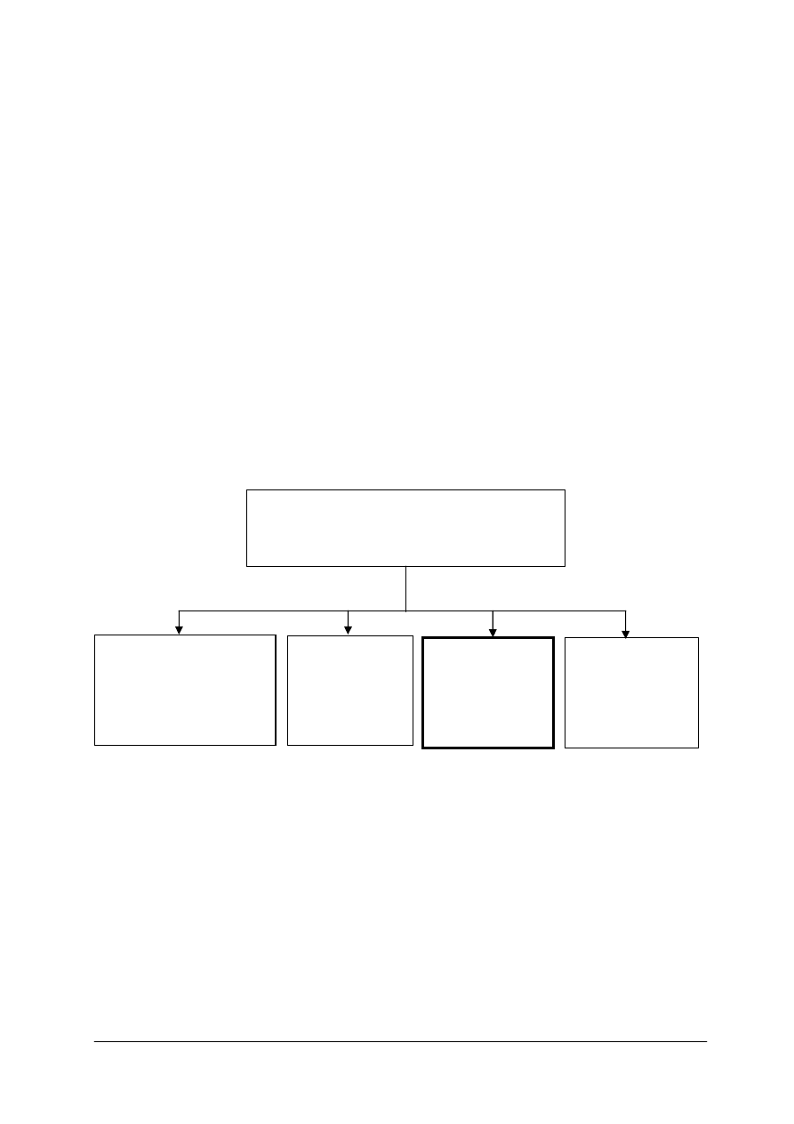
Schemat układu jednostek modułowych
314[05].O1
Środowisko pracy
314[05].O1.01
Przestrzeganie przepisów
bezpieczeństwa i higieny
pracy, ochrony
przeciwpożarowej i ochrony
środowiska
314[05].O1.02
Określanie
warunków
funkcjonowania
człowieka w
środowisku pracy
314[05].O1.03
Posługiwanie się
językiem
angielskim
zawodowym
314[05].O1.04
Przestrzeganie
przepisów
lotniczych

„Projekt współfinansowany ze środków Europejskiego Funduszu Społecznego”
4
2. WYMAGANIA WSTĘPNE
Przystępując do realizacji programu jednostki modułowej, powinieneś umieć:
−
posługiwać się językiem angielskim na poziomie B1/B2, lub FCE,
−
poprawnie interpretować znaczenia rzeczowników złożonych w języku angielskim,
−
pisać prosty list formalny,
−
posługiwać się podstawową wiedzę w zakresie techniki lotniczej w języku polskim,
−
posługiwać się podstawowymi pojęciami z zakresu matematyki, geometrii, fizyki,
chemii, elektrotechniki i elektroniki,
−
korzystać z różnych źródeł informacji,
−
obsługiwać komputer, korzystać z Internetu i wyszukiwarek internetowych,
−
współpracować w grupie.

„Projekt współfinansowany ze środków Europejskiego Funduszu Społecznego”
5
3. CELE KSZTAŁCENIA
W wyniku realizacji programu jednostki modułowej, powinieneś umieć:
– scharakteryzować statek powietrzny stosownie do rodzaju i przeznaczenia,
– scharakteryzować elementy statków powietrznych i ich zespoły,
– opisać i sklasyfikować przyrządy i urządzenia wchodzące w skład awioniki,
– zastosować
terminologię
dotyczącą
podstawowych
operacji
obróbki
ręcznej
i mechanicznej,
– odczytać ze zrozumieniem dokumentację techniczną statków powietrznych,
– dokonać pisemnego i ustnego zamówienia części zamiennych do wykonania obsługi
statku powietrznego,
– wypełnić formularze poświadczenia obsługi technicznej statku powietrznego,
– odczytać ze zrozumieniem przepisy organizacji: JAA, ICAO i UE(EASA),
– napisać list, pismo, faks, e-mail w sprawach zawodowych,
– poprowadzić rozmowy w sprawach zawodowych i sytuacjach z życia codziennego.

„Projekt współfinansowany ze środków Europejskiego Funduszu Społecznego”
6
4. MATERIAŁ NAUCZANIA
4.1. Konstrukcja statku powietrznego
4.1.1. Materiał nauczania
aircraft
manned
RPV
surround
UAV
unmanned
vehicle
1) An aircraft is a vehicle which is able to fly through the air (or through
any other atmosphere). All the human activity which surrounds aircraft is
called aviation. (Most rocket vehicles are not aircraft because they are
not supported by the surrounding air).
Manned aircraft are flown by a pilot. Until ca. the 1960s, unmanned
aircraft were called drones. During the 1960s, the US military brought
the term Remotely Piloted Vehicles (RPV) into use. More recently the
term Unmanned Aerial Vehicle (UAV) has become common.
aerodynes
aerostats
airship
buoyancy
canopies
density
displace
float
gasbags
hydrogen
power
powered
structure weight
2) Aircraft fall into two broad categories: Lighter-than-air, called
aerostats, and heavier-than-air, called aerodynes.
Rys.1. A hot air balloon in flight. [9]
Aerostats use buoyancy to float in the air in much the same way that
ships float on the water. They are characterized by one or more large
gasbags or canopies, filled with a relatively low density gas such as
helium, hydrogen or hot air, which is lighter than the surrounding air.
When the weight of this is added to the weight of the aircraft structure, it
adds up to the same weight as the air that the craft displaces.
Small hot air balloons called sky lanterns date back to the 3rd Century
BC and were only the second type of aircraft to fly, the first being kites.
Nowadays we say that a balloon is an unpowered aerostat, whilst an
airship is a powered one.
law
lift
push
thrust
ward
3) Heavier than air – aerodynes
Heavier-than-air aircraft must find some way to push air or gas
downwards, so that a reaction occurs (by Newton's laws of motion) to
push the aircraft upwards. This dynamic movement through the air is the
origin of the term aerodyne. There are two ways to produce dynamic
upthrust: aerodynamic lift, and powered lift in the form of engine thrust.

„Projekt współfinansowany ze środków Europejskiego Funduszu Społecznego”
7
aerodynamics
aerofoil
craft
horizontal
spin
wing
rotor
4) Aerodynamic lift is the most common, with airplanes kept in the air by
the forward movement of wings, and rotorcraft by spinning wing-shaped
rotors. A wing is a flat, horizontal surface, usually shaped in cross-
section as an aerofoil. To fly it must move forwards through the air; this
movement of air over the aerofoil shape deflects air downward to create
an equal and opposite upward force, called lift, according to Newton's
third law of motion.
steady
STOL
take off
transfer
vertical
VTOL
5) The initialism VTOL (vertical take off and landing) is applied to
aircraft that can take off and land vertically. Most are rotorcraft. Others,
such as the Hawker Siddeley Harrier, take off and land vertically using
powered lift and transfer to aerodynamic lift in steady flight. STOL
stands for short take off and landing.
fixed- wing
canard
configuration
control surface
elevator
foreplane
fuselage
rudder
stabilizer
tailless
tailplane
tandem wing
6) Airplanes or airplanes are technically called fixed-wing aircraft.
Airplanes are generally characterized by their wing configuration.
In a conventional configuration, the main wings are placed in front of
a smaller stabilizer surface or tailplane. The canard reverses this, placing
a small foreplane forward of the wings, near the nose of the aircraft.
Canards are becoming more common as supersonic aerodynamics grows
more mature and because the forward surface contributes lift during
straight-and-level flight. The tandem wing type has two wings of similar
size, one at the front and one at the back. In a tailless design the lift and
horizontal control surfaces are combined. The ultimate expression of this
is the flying wing, where there is no central fuselage, and perhaps even
no separate vertical control surface (e.g., the B-2 Spirit).
biplane
drag
sesquiplane
strut
triplane
7) Sometimes two or more wings are stacked one above the other.
A biplane has two wings, and a triplane has three, quadruplanes (four)
and above have never been successful. Up until the 1930's, biplanes were
the most common. Triplanes were only occasionally made, especially for
a brief period during the First World War due to their high
manoeuvrability as fighters.
brace
cantilever
high-wing
low-wing
mid-wing
monoplane
multiplane
multi-plane
wire
8) A sesquiplane is similar to a biplane, but with the lower wing much
reduced in size. Most multi-plane designs are braced, with struts and/or
wires holding the wings in place. A monoplane has only one wing. Some,
especially early designs, are also braced, because this allows a much
lighter weight than a clean, unbraced cantilever design. But bracing
causes a large amount of drag at higher speeds, so it is no longer used for
faster designs. Monoplanes are also classified as high-wing, mid-wing or
low-wing, according to where on the fuselage the wing is attached.
chord
forward sweep
swept wing
tapered
9) Most low-speed airplanes have a straight wing, which may be
constant-chord, or tapered so that it decreases in chord towards the tip.
For flight near or above the speed of sound, a swept wing is usually used,
where the wing angles backwards towards the tips (though forward
sweep is occasionally experimented with, and M-wing designs which
reverse direction half way along have been suggested).

„Projekt współfinansowany ze środków Europejskiego Funduszu Społecznego”
8
crescent
crop
delta
double-curved
ogival delta
leading edge
sharp
swing-wing
trailing edge
10) A notable variation is the delta wing, which is shaped like a triangle:
the leading edge is sharply swept, but the trailing edge is straight; one
common form is the cropped delta, which merges into the tapered swept
category, and an especially graceful form is the double-curved ogival
delta found for example on Concorde. Another variation is the crescent
wing, seen for example on the Handley Page Victor, which is sharply
swept inboard, with reduced sweep for the outboard section. A variable-
geometry wing, or swing-wing, can change the angle of sweep in flight.
It has been employed in a few examples of combat aircraft, the first
production type being the General Dynamics F-111.
bulkheads
formers
frames
longerons
monocoque
semimonocoque
stringers
11) Semimonocoque construction.
The semimonocoque fuselage is constructed primarily of the alloys of
aluminum and magnesium, although steel and titanium are found in areas
of high temperatures. Primary bending loads are taken by the longerons,
which usually extend across several points of support. The longerons are
supplemented by other longitudinal members, called stringers. Stringers
are more numerous and lighter in weight than longerons. The vertical
structural members are referred to as bulkheads, frames, and formers.
The heaviest of these vertical members are located at intervals to carry
concentrated loads and at points where fittings are used to attach other
units, such as the wings, powerplants, and stabilizers.
lateral axis
longitudinal
parallel
Principal member
ribs
spars
truss
12) Wing construction.
The main structural parts of a wing are the spars, the ribs or bulkheads,
and the stringers or stiffeners. Spars are the principal structural members
of the wing. They correspond to the longerons of the fuselage. They run
parallel to the lateral axis, or toward the tip of the wing, and are usually
attached to the fuselage by wing fittings, plain beams, or a truss system.
Spars may be made of metal or wood depending on the design criteria of
a specific aircraft. Most aircraft recently manufactured use spars of solid
extruded aluminum or short aluminum extrusions riveted together to
form a spar.
floatplane
seaplane
13) Seaplanes and floatplanes differ in that a seaplane has the bottom of
its fuselage shaped hydrodynamically and it sits directly on the water
when at rest, while a floatplane has two or more floats attached below the
rest of the aircraft so that the fuselage remains clear of the water at all
times.
aerofoil
autogyro
directly
disc
gyrodyne
hybrid
propulsion
rotor kite
spin
tether
tether
tilt
14) Rotorcrafts, or rotary-wing aircraft, use a spinning rotor with aerofoil
section blades (a rotary wing) to provide lift. Types include helicopters,
autogyros and various hybrids such as gyrodynes and compound
rotorcraft. Helicopters have powered rotors. The rotor is driven (directly
or indirectly) by an engine and pushes air downwards to create lift. By
tilting the rotor forwards, the downwards flow is tilted backwards,
producing thrust for forward flight.
Autogyros or gyroplanes have unpowered rotors, with a separate power
plant to provide thrust. The rotor is tilted backwards. As the autogyro
moves forward, air blows upwards through it, making it spin. This
„Projekt współfinansowany ze środków Europejskiego Funduszu Społecznego”
9
tow
ward
spinning dramatically increases the speed of airflow over the rotor, to
provide lift. Juan de la Cierva (a Spanish civil engineer) used the product
name autogiro, and Bensen used gyrocopter. Rotor kites, such as the
Focke Achgelis Fa 330 are unpowered autogyros, which must be towed
by a tether to give them forward speed.
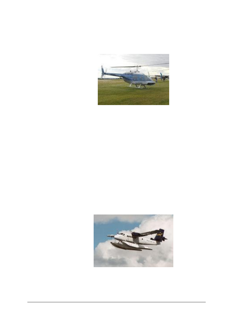
Rys.2. Bell 206B JetRanger III helicopter [10]
Gyrodynes are a form of helicopter, where forward thrust is obtained
from a separate propulsion device rather than from tilting the rotor. The
definition of a 'gyrodyne' has changed over the years, sometimes
including equivalent autogiro designs. The most important characteristic
is that in forward flight air does not flow significantly either up or down
through the rotor disc but primarily across it. The Heliplane is a similar
idea.
Compound rotorcrafts have wings which provide some or all of the lift in
forward flight.
axis
contra-prop
duct
fairing
fan
gear
hub
jet
propeller
propfan
ring
turbine
turboprop
15) A propeller comprises a set of small, wing-like aerofoils set around a
central hub and aligned in the direction of travel. Spinning the propeller
creates aerodynamic lift, or thrust, in a forward direction. A contra-prop
arrangement has a second propeller close behind the first one on the same
axis, which rotates in the opposite direction.
Turbine engines need not be used as jets (see below), but may be geared
to drive a propeller in the form of a turboprop. Modern helicopters also
typically use turbine engines to power the rotor.
Rys.3. A turboprop-engined DeHavilland Twin Otter adapted as a floatplane [11]
A variation on propellers is to use many broad blades to create a fan.
These fans are traditionally surrounded by a ring-shaped fairing or duct,
as ducted fans. Some experimental designs do not use a duct, and are
sometimes called propfans. How to tell whether it's a propeller or a fan?
„Projekt współfinansowany ze środków Europejskiego Funduszu Społecznego”
10
Look at it from the front when stationary: if you can see in between the
blades then it is a propeller, while if the blades pretty much block the
view it is a fan.
acceleration
altitude
burning
efficient
eject
exhaust
magnitude
mass
take in
16) Jet engines
Jet engines provide thrust by taking in air, burning it with fuel, and
accelerating the exhaust rearwards so that it ejects at high speed. The
reaction against this acceleration provides the engine thrust.
F = m · a, where “m” is the mass of accelerated air and fuel throughout
the engine and “a” is the magnitude of acceleration.
Jet engines can provide much higher thrust than propellers, and are
naturally efficient at higher altitudes, being able to operate above
40,000 ft (12,000 m). They are also much more fuel-efficient than
rockets. Consequently, nearly all high-speed and high-altitude aircraft
use jet engines.
booster
bypass
crude
hybrid design
pulse jet
ramjet
ramjet
refuel
stationary
tanker
turbojet
17) The early turbojet and modern turbofan use a spinning turbine to
create airflow for takeoff and to provide thrust, but this is not absolutely
necessary. Other designs include the crude pulse jet, high-speed ramjet
and the still-experimental supersonic-combustion ramjet or scramjet.
These designs require an existing airflow to work and cannot work when
stationary, so they must be launched by a catapult or rocket booster, or
dropped from a mother ship. The engines of the Lockheed blackbird were
a hybrid design - the aircraft took off and landed in jet turbine
configuration, and for high-speed flight the turbine was bypassed to form
a ramjet.
airliner
bomber
fighter
transport
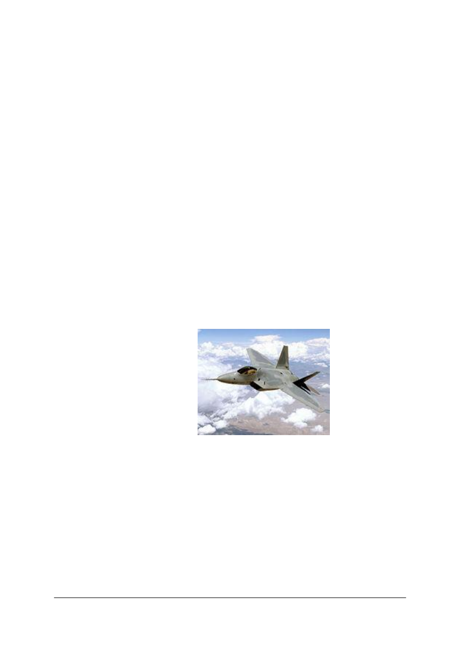
18) Military aircraft
Rys.4. The fifth-generation Military Aircraft, F-22 Raptor [12]
Combat aircraft like fighters or bombers represent only a minority of the
category. Many civil aircraft have been produced in separate models for
military use, such as the civil Douglas DC-3 airliner, which became the
military C-47/C-53/R4D transport in the U.S.
19) List of aircraft by category
1 Civilian Aircraft
1.1 Airliners
1.2 Cargo planes
1.3 General aviation
1.4 Agricultural aircraft
1.5 Business aircraft
1.6 Civilian Seaplane, Flying Boats, and Amphibious Aircraft

„Projekt współfinansowany ze środków Europejskiego Funduszu Społecznego”
11
1.7 Civilian Helicopters
1.8 Sailplanes
1.9 Civil Research Aircraft, Prototypes and Specials
2 Military Aircraft
2.1 Bombers, Strike, Ground attack, gunships
2.2 Patrol, Anti-Submarine and Electronic Warfare aircraft
2.3 Military transports, tankers, and utility
2.4 Reconnaissance aircraft
2.5 Close air support/Counterinsurgency
2.6 Fighter aircraft, nightfighters and heavy fighters
2.7 Military Trainers
2.8 Military Helicopters and autogyros
2.9 Military Research Aircraft, Prototypes and Specials
4.1.2. Pytania sprawdzające
Odpowiadając na pytania, sprawdzisz, czy jesteś przygotowany do wykonania ćwiczeń.
1. Are all aircraft flown by a pilot?
2. Why is and isn’t a space-shuttle an aircraft?
3. What is a UAV flown by?
4. What does RPV refer to?
5. What was the first aircraft to fly?
6. What makes aerostats fly in the air?
7. What makes the heavier than air aircraft fly?
8. What is the difference between conventional aircraft and flying wing?
9. How many wings has a quadruplane got?
10. What are advantages and disadvantages of a cantilever wing design?
11. What are the most common shapes of aircraft wings?
12. What is the difference between a seaplane and a floatplane?
13. What is the main difference between helicopters and autogyros?
14. What are the main parts of an aircraft structure?
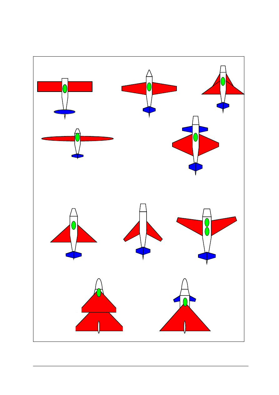
4.1.3. Ćwiczenia
Ćwiczenie 1
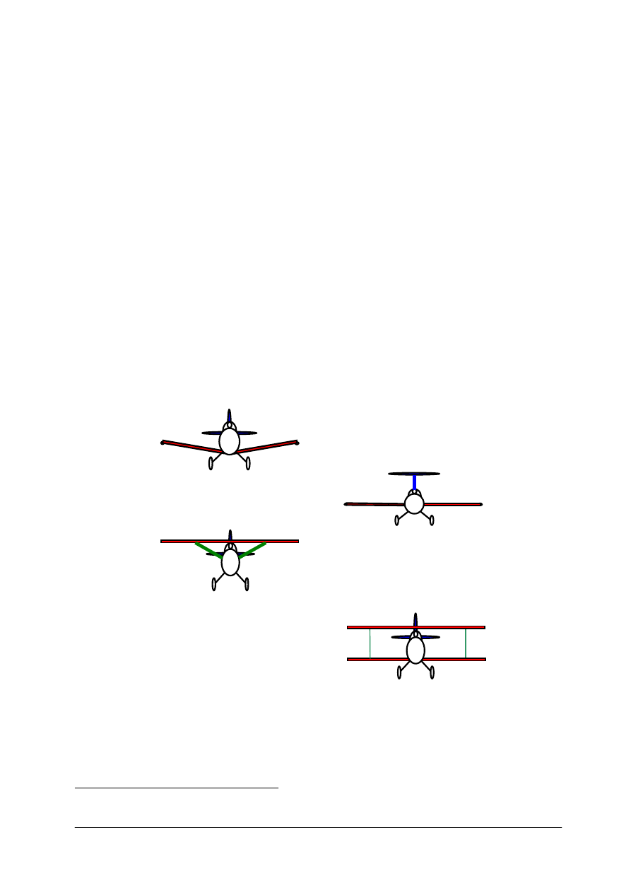
Na podstawie fragmentów 6–10 materiału nauczania z rozdziału 4.1.1. Poradnika dla
ucznia określ układ aerodynamiczny statków powietrznych przedstawionych na rysunku do
ćwiczenia 1. Określ kształty elementów tworzących rysunek statku powietrznego.
Sposób wykonania ćwiczenia
Aby wykonać ćwiczenie, powinieneś:
1) zorganizować stanowisko pracy do wykonania ćwiczenia,
2) przeanalizować zadania,
3) sprawdzić w słowniku określenia dotyczące podstawowych figur geometrycznych,
4) porównać nazwy figur geometrycznych z nazwami frazeologicznymi używanymi
w lotnictwie,
5) porównać wynik pracy z pracami innych uczniów.
„Projekt współfinansowany ze środków Europejskiego Funduszu Społecznego”
12
Wyposażenie stanowiska pracy:
–
słownik,
–
materiały do pisania.
Rys. do ćwiczenia 1. Wing planforms.
A
B
C
D
E
F
G
H
I
J
„Projekt współfinansowany ze środków Europejskiego Funduszu Społecznego”
13
Ćwiczenie 2
Na rysunku do ćwiczenia 2 przedstawione są cztery konfiguracje ustawienia skrzydeł
w stosunku do kadłuba. Podaj słowną instrukcję do narysowania podobnego rysunku
używając określeń geometrycznych (okrąg, linia ukośna). Wykonaj to samo ćwiczenie
używając fachowych określeń lotniczych (kadłub, skrzydło, ster wysokości). Pozostałe osoby
w grupie będą rysowały zgodnie z twoimi instrukcjami. Powtórz ćwiczenie dla sylwetek
samolotów z rysunku do ćwiczenia 1.
Sposób wykonania ćwiczenia
Aby wykonać ćwiczenie, powinieneś:
1) zorganizować stanowisko pracy do wykonania ćwiczenia,
2) przeanalizować zadania,
3) sprawdzić w słowniku określenia dotyczące podstawowych figur geometrycznych,
4) porównać nazwy figur geometrycznych z nazwami frazeologicznymi używanymi
w lotnictwie,
5) porównać wynik pracy z pracami innych uczniów.
Wyposażenie stanowiska pracy:
– papier formatu A4,
– ołówek,
– flamastry,
– poradnik dla ucznia,
– słownik.
Rys. do ćwiczenia 2. Wing position.
Ćwiczenie 3
Przygotuj trwającą 4-5 minut prezentację w programie PowerPoint, lub Impress
przedstawiającą budowę wybranego typu statku powietrznego.
Aby znaleźć potrzebne informacje i ilustracje skorzystaj z encyklopedii internetowej
http://en.wikipedia.org/wiki/Main_Page, lub innych źródeł. Wykorzystaj słownictwo podane
w 19 fragmencie materiału nauczania 4.1.1.
A
C.
D
B

„Projekt współfinansowany ze środków Europejskiego Funduszu Społecznego”
14
Proponowane typy statków powietrznych:
– PZL M-28,
– AN-2,
– Aviat Eagle II,
– PA 34 Seneca,
– Curtiss_YA-14,
– Bell XP-83,
– Cessna 172,
– PZL-104 Wilga,
– Mirage 2000,
– Airbus A-380,
– Boeing 767,
– B-2 Spirit,
– F-16,
– Eurofighter Typhoon,
– MQ1 Predator.
Sposób wykonania ćwiczenia
Aby wykonać ćwiczenie, powinieneś:
1) zorganizować stanowisko pracy do wykonania ćwiczenia,
2) przeanalizować zadania,
3) wyszukać w Internecie charakterystykę wybranego statku powietrznego,
4) wykonać prezentację uwzględniając słownictwo zawarte w materiale nauczania,
5) porównać wynik pracy z pracami innych uczniów.
Wyposażenie stanowiska pracy:
–
słownik,
–
komputer z dostępem do Internetu,
–
materiały do pisania.
4.1.4. Sprawdzian postępów
Czy potrafisz:
Tak
Nie
1) dokonać podziału statków powietrznych ze względu na wielkość
załogi?
2) dokonać podziału statków powietrznych ze względu na ciężar?
3) wyjaśnić zasadę lotu aerostatu?
4) wyjaśnić mechanizm powstawania siły nośnej na skrzydle?
5) wymienić główne elementy konstrukcyjne statku powietrznego?
6) opisać układ aerodynamiczny samolotu?
7) opisać sposób powstawania siły nośnej w śmigłowcu?
8) opisać sposób powstawania siły nośnej w wiatrakowcu?
9) podać przykłady zastosowania silników turbinowych i odrzutowych?
10) wymienić główne rodzaje silników lotniczych?
11) wymienić rodzaje statków powietrznych cywilnych i wojskowych ze
względu na przeznaczenie?
12) wymienić główne elementy konstrukcyjne skrzydła?
13) wymienić główne elementy konstrukcyjne kadłuba?

„Projekt współfinansowany ze środków Europejskiego Funduszu Społecznego”
15
4.2. Systemy i instalacje samolotu
4.2.1. Materiał nauczania
combustion
filters
fluid
generator
hydraulic
hydrostatic
kinetic energy
liquid
piping
pump
valves
1) A hydraulic or hydrostatic drive system or hydraulic power
transmission is a drive or transmission system that makes use of
a hydraulic fluid under pressure to drive machinery. All liquids and all
gases are fluids. Such a system basically consists of: Generator part of
the transmission, in general a hydraulic pump, driven by an electric
motor, a combustion engine or a windmill. Valves, filters, piping etc. to
guide and control the system. Motor part of the transmission a hydraulic
motor or hydraulic cylinder to drive the machinery. Hydrostatic means
that the energy comes from the flow and the pressure, but not from the
kinetic energy of the flow.
actuated
confined
confined liquid
diminish
fluid
gas
incompressible
law
liquid
rest
transmit
2) Principle of hydraulic drive system.
Pascal's law is the basis of hydraulic drive systems. Hydraulic system
liquids are used primarily to transmit and distribute forces to various
units to be actuated. Liquids are able to do this because they are almost
incompressible. Pascal's Law states that pressure applied to any part of
a confined and connected body of an incompressible fluid at rest is
transmitted with undiminished intensity to every other part.
dilute
flow
resistance
viscosimeter
viscosity
3) Viscosity.
One of the most important properties of any hydraulic fluid is its
viscosity. Viscosity is internal resistance to flow. A liquid such as
gasoline flows easily (has a low viscosity) while a liquid such as tar
flows slowly (has a high viscosity). Viscosity increases with temperature
decreases. The viscosity of a liquid is measured with a viscosimeter or
viscometer.
breakdown
bypass
bypass valve
clogged
contamination
deposit
impurity
inline
malfunction
objectionable
particles
pressure line
pump
reservoir
route
safeguard
screen
secured
selector valve
strain
suspension
wear
4) Filters.
A filter is a screening or straining device used to clean the hydraulic
fluid, thus preventing foreign particles and contaminating substances
from remaining in the system. If such objectionable material is not
removed, it may cause the entire hydraulic system of the aircraft to fail
through the breakdown or malfunctioning of a single unit of the system.
The hydraulic fluid holds in suspension tiny particles of metal that are
deposited during the normal wear of selector valves, pumps, and other
system components. Filters may be located within the reservoir, in the
pressure line, in the return line, or in any other location where the
designer of the system decides that they are needed to safeguard the
hydraulic system against impurities. Most filters used in modern aircraft
are of the inline type. The inline filter assembly is comprised of three
basic units: head assembly, bowl, and element. The head assembly is that
part which is secured to the aircraft structure and connecting lines.
Within the head there is a bypass valve which routes the hydraulic fluid
directly from the inlet to the outlet port if the filter element becomes
clogged with foreign matter.

„Projekt współfinansowany ze środków Europejskiego Funduszu Społecznego”
16
adjustable
efficiency
ratio
servo-motors
swept volume
throttling
plunger
torque
5) A hydraulic pump with a small swept volume that asks for a small
torque combined with a hydraulic motor with a large swept volume that
gives a large torque. In such a way a transmission with a certain ratio can
be built. Most hydraulic drive systems make use of hydraulic cylinders.
Here the same principle is used. A small torque can be transmitted in
a large force. By throttling the fluid between generator part and motor
part, or by using hydraulic pumps and/or motors with adjustable swept
volume, the ratio of the transmission can be changed easily. In case
throttling is used, the efficiency of the transmission is limited, If
adjustable pumps and motors are used, the efficiency however is very
large. In fact up to say 1980, a hydraulic drive system had hardly
competition from other adjustable (electric) drive systems. Nowadays
electric drive systems using electric servo-motors can be controlled in an
excellent way and can easily compete with rotating hydraulic drive
systems. Hydraulic cylinders are in fact without competition for linear
(high) forces. For these cylinders anyway hydraulic systems will remain
of interest and if such a system is available, it is easy and logical to use
this system also for the rotating drives of the system.
compensator
fixed delivery
pumps
quantity of fluid
variable/constant
delivery
6) Hydraulic pump
The smallest gear pumps (except miniature ones) have a swept volume of
1 cm³ and the largest axial plunger pump that is available from stock will
have a swept volume of 1000 cm³. For continuous hydraulic drives, the
maximum working pressure will be some 200 bars.
7) Power Driven Pumps
Many of the power driven hydraulic pumps of current aircraft are of
variable delivery, compensator controlled type. There are some constant
delivery pumps in use. Principles of operation are the same for both types
of pumps.
pressure
regulator
pump rpm
varying output
automatically
output
within
8) Constant delivery pumps are sometimes called constant volume or
fixed delivery pumps. They deliver a fixed quantity of fluid per
revolution, regardless of the pressure demands. Since the constant
delivery pump provides a fixed quantity of fluid during each revolution
of the pump, the quantity of fluid delivered per minute will depend upon
pump rpm. When a constant delivery pump is used in a hydraulic system
in which the pressure must be kept at a constant value, a pressure
regulator is required.
9) A variable delivery pump has a fluid output that is varied to meet the
pressure demands of the system by varying its fluid output. The pump
output is changed automatically by a pump compensator within the
pump.
durability
gear
gerotor
piston
vane
10) Pumping Mechanisms
Various types of pumping mechanisms are used in hydraulic pumps, such
as gears, gerotors, vanes, and pistons. The piston type mechanism is
commonly used in power driven pumps because of its durability and
capability to develop high pressure. In 3,000 psi hydraulic systems,
piston type pumps are nearly always used.
„Projekt współfinansowany ze środków Europejskiego Funduszu Społecznego”
17
clearance
clockwise
counterclockwise
gear teeth
housing
inlet port
meshed gears
outlet port
reservoir
trapped
11) Gear Type Pump
A gear type power pump consists of two meshed gears that revolve in
a housing. The driving gear is driven by the aircraft engine or some other
power unit. The driven gear meshes with, and is driven by, the driving
gear. Clearance between the teeth as they mesh, and between the teeth
and the housing, is very small. The inlet port of the pump is connected to
the reservoir, and the outlet port is connected to the pressure line. When
the driving gear turns in a counterclockwise direction, it turns the driven
gear in a clockwise direction. As the gear teeth pass the inlet port, fluid is
trapped between the gear teeth and the housing, and is then carried
around the housing to the outlet port.
blades
bore
coupling
displaced
drawn
hollow rotor
off center
sleeve
slots
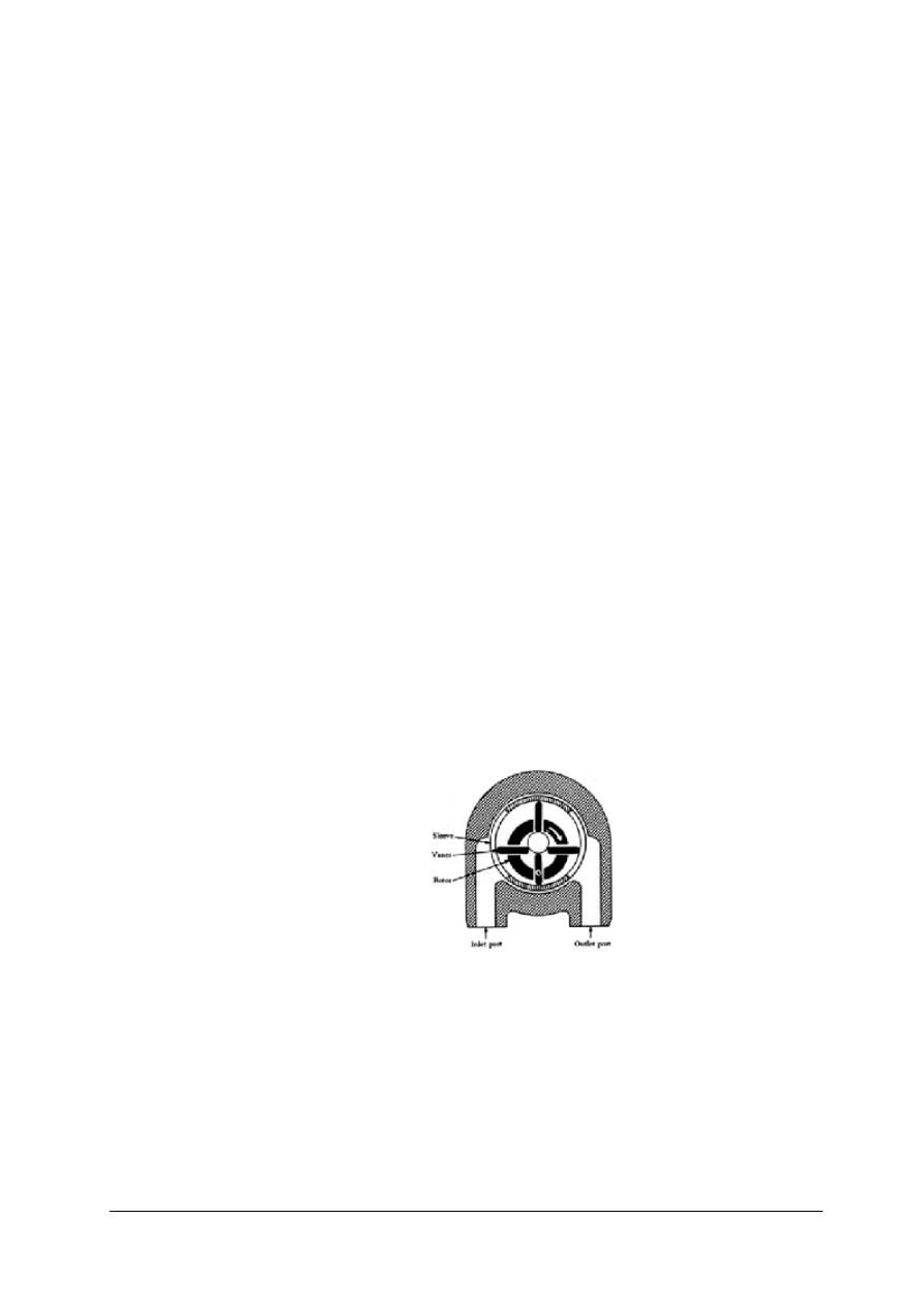
12) Vane Type Pump
The vane type power pump consists of a housing containing four vanes
(blades), a hollow steel rotor with slots for the vanes, and a coupling to
turn the rotor.
The rotor is positioned off center within the sleeve. The vanes, which are
mounted in the slots in the rotor, together with the rotor, divide the bore
of the sleeve into four sections. As the rotor turns, each section, in turn,
passes one point where its volume is at a minimum, and another point
where its volume is at a maximum. The volume gradually increases from
minimum to maximum during one-half of a revolution, and gradually
decreases from maximum to minimum during the second half of the
revolution. As the volume of a given section is increasing, that section is
connected to the pump inlet port through a slot in the sleeve. Since
a partial vacuum is produced by the increase in volume of the section,
fluid is drawn into the section through the pump inlet port and the slot in
the sleeve. As the rotor turns through the second half of the revolution,
and the volume of the given section is decreasing, fluid is displaced out
of the section, through the slot in the sleeve, through the outlet port, and
out of the pump.
Rys.5. Vane type pump. [4]
accessory drive
case
base
drive coupling
engage
female splines
flange
housing
male splines
piston
plunger
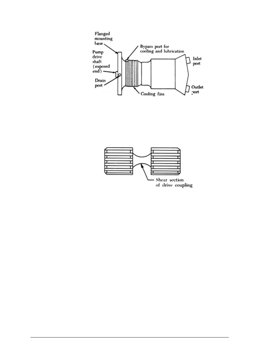
13) Piston type power driven pumps have flanged mounting bases for the
purpose of mounting the pumps on the accessory drive cases of aircraft
engines and transmissions. A pump drive shaft, which turns the
mechanism, extends through the pump housing slightly beyond the
mounting base.
„Projekt współfinansowany ze środków Europejskiego Funduszu Społecznego”
18
shaft
torque
Rys.6. Piston type pump. [4]
Torque from the driving unit is transmitted to the pump drive shaft by
a drive coupling. The drive coupling is a short shaft with a set of male
splines on both ends. The splines on one end engage with female splines
in a driving gear; the splines on the other end engage with female splines
in the pump drive shaft.
Rys.7. Pump drive male coupling with shear section. [4]
diameter
jammed
midway
parallel
perpendicular
rotary
reciprocal
motion
safety devices
shear
symmetrical
valving
14) Pump drive couplings are designed to serve as safety devices. The
shear section of the drive coupling, located midway between the two sets
of splines, is smaller in diameter than the splines. If the pump becomes
unusually hard to turn or becomes jammed, this section will shear,
preventing damage to the pump or driving unit.
The basic pumping mechanism of piston type pumps consists of
a multiple bore cylinder block, a piston for each bore, and a valving
arrangement for each bore. The purpose of the valving arrangement is to
let fluid into and out of the bores as the pump operates. The cylinder
bores lie parallel to and symmetrically around the pump axis. The term
"axial piston pump" is often used in referring to pumps of this
arrangement. Basically these types of pumps changes rotary motion into
reciprocal piston motion.
actuator
clevis
cylinder head
linear motor
multiply
piston rod
sealed
shell
stroke
volume
15) Hydraulic cylinders (also called linear hydraulic motors) are
mechanical actuators that are used to give a linear force through a linear
stroke. Very simple hydraulic cylinders are used in presses; here the
cylinder consists out of a volume in a piece of iron with a plunger pushed
in it and sealed with a cover. By pumping hydraulic fluid in the volume,
the plunger is pushed out with a force of plunger area multiplied by
pressure. More sophisticated cylinders have a body with end cover,
a piston rod with piston and a cylinder head. At one side the bottom is

„Projekt współfinansowany ze środków Europejskiego Funduszu Społecznego”
19
connected to a single clevis, whereas at the other side, the piston rod also
is foreseen with a single clevis. The cylinder shell normally has hydraulic
connections at both sides. A connection at bottom side and one at
cylinder head side. If oil is pushed under the piston, the piston-rod is
pushed out and oil that was between the piston and the cylinder head is
pushed back to the oil-tank again.
balanced
actuator
double acting
extend
retract
single acting
16) In case the retracted length of the cylinder is too long for the cylinder
to be build in the structure. In this case telescopic cylinders can be used.
One has to realize that for simple pushing applications telescopic
cylinders might be available easily; for higher forces and/or double
acting cylinders, they must be designed especially and are very
expensive. If hydraulic cylinders are only used for pushing and the piston
rod is brought in again by other means, one can also use plunger
cylinders. Plunger cylinders have no sealing over the piston, or the piston
does not exist. This means that only one oil connection is necessary. In
general the diameter of the plunger is rather large compared with
a normal piston cylinder.
conceptually
interchangeable
motor
rotary
17) The hydraulic motor is the rotary counterpart of the hydraulic
cylinder. Conceptually, a hydraulic motor should be interchangeable with
hydraulic pump, because it performs the opposite function. However,
most hydraulic pumps cannot be used as hydraulic motors because they
cannot be backdriven.
excessive
heavy duty
relief
stand up
thermal
thermal
expansion
18) Hydraulic valves
These valves are usually very heavy duty to stand up to high pressures.
Some special valves can control the direction of the flow of fluid and act
as a control unit for a system.
Thermal relief valve. The pressure relief valve is used to relieve
excessive pressures that may exist due to thermal expansion of the fluid.
pressure gauge
pressure
regulator
pressure relief
valve
rupture
19) Pressure regulation.
Hydraulic pressure must be regulated in order to use it to perform the
desired tasks. Pressure regulating systems will always use three
elemental devices; a pressure relief valve, a pressure regulator and a
pressure gauge.
A pressure relief valve is used to limit the amount of pressure being
exerted on a confined liquid. This is necessary to prevent failure of
components or rupture of hydraulic lines under excessive pressures. The
pressure relief valve is, in effect, a system safety valve.
acute angle
angle
ball type
cone
contoured
leakage
machined
matched angles
obtuse angle
poppet type
20) The most common types of valve are:
Ball type. In pressure relief valves with a ball type valving device, the
ball rests on a contoured seat. Pressure acting on the bottom of the ball
pushes it off its seat, allowing the fluid to bypass.
Sleeve type. In pressure relief valves with a sleeve type valving device,
the ball remains stationary and a sleeve type seat is moved up by the fluid
pressure. This allows the fluid to bypass between the ball and the sliding
sleeve type seat.

„Projekt współfinansowany ze środków Europejskiego Funduszu Społecznego”
20
right angle
sleeve type
valve seat
Poppet type. In pressure relief valves with a poppet type valving device,
a cone shaped poppet may have any of several design configurations;
however, it is basically a cone and seat machined at matched angles to
prevent leakage.
predeterminated
pressurized
range
resistance
termed
virtually
21) Pressure Regulators
The term "pressure regulator" is applied to a device used in hydraulic
systems that are pressurized by constant delivery type pumps. One
purpose of the pressure regulator is to manage the output of the pump to
maintain system operating pressure within a predetermined range. The
other purpose is to permit the pump to turn without resistance (termed
unloading the pump) at times when pressure in the system is within
normal operating range. The pressure regulator is so located in the
system that pump output can get into the system pressure circuit only by
passing through the regulator. The combination of a constant delivery
type pump and the pressure regulator is virtually the equivalent of
a compensator controlled, variable delivery type pump.
bourdon tube
drain
face
moisture
vent
22) Pressure Gauge
The purpose of this gauge is to measure the pressure, in the hydraulic
system, used to operate hydraulic units on the aircraft. The gauge uses
a Bourdon tube and a mechanical arrangement to transmit the tube
expansion to the indicator on the face of the gauge. A vent in the bottom
of the case maintains atmospheric pressure around the Bourdon tube. It
also provides a drain for any accumulated moisture.
chambers
continually
cycle
dampen
leak
preset
rubber
diaphragm
sphere
supplement
supplement
surge
23) The accumulator is a steel sphere divided into two chambers by
a synthetic rubber diaphragm. The upper chamber contains fluid at
system pressure, while the lower chamber is charged with air.
The function of an accumulator is to:
a. Dampen pressure surges in the hydraulic system caused by actuation of
a unit and the effort of the pump to maintain pressure at a preset level.
b. Aid or supplement the power pump when several units are operating at
once by supplying extra power from its "accumulated" or stored power.
c. Store power for the limited operation of a hydraulic unit when the
pump is not operating.
d. Supply fluid under pressure to compensate for small internal or
external (not desired) leaks which would cause the system to cycle
continuously by action of the pressure switches continually "kicking in."
as such
check valve
exclusively
hose
integral part
must be made
to flow
orifice
restricted
tubing
within itself
24) Check Valves
For hydraulic components and systems to operate as intended, the flow of
fluid must be rigidly controlled. Fluid must be made to flow according to
definite plans. Many kinds of valve units are used for exercising such
control. One of the simplest and most commonly used is the check valve
which allows free flow of fluid in one direction, but no flow or
a restricted flow in the opposite direction.
Check valves are made in two general designs to serve two different
needs. In one, the check valve is complete within itself. It is
interconnected with other components with which it operates, by means

„Projekt współfinansowany ze środków Europejskiego Funduszu Społecznego”
21
of tubing or hose. Check valves of this design are commonly called in-
line check valves. There are two types of in-line check valves, the simple
type in-line check valve and the orifice type in-line valve. In the other
design, the check valve is not complete within itself because it does not
have a housing exclusively its own. Check valves of this design are
commonly called integral check valves. This valve is actually an integral
part of some major component and, as such, shares the housing of that
component.
pathway
reverse
select
actuating unit
pathway
simultaneous
flow
25) Line Disconnect or Quick Disconnect Valves
These valves are installed in hydraulic lines to prevent loss of fluid when
units are removed. Such valves are installed in the pressure and suction
lines of the system just in front of and immediately behind the power
pump.
26) Selector valves.
Selector valves are used to control the direction of movement of an
actuating unit. A selector valve provides a pathway for the simultaneous
flow of hydraulic fluid into and out of a connected actuating unit.
A selector valve also provides a means of immediately and conveniently
switching the directions in which the fluid flows through the actuator,
reversing the direction of movement.
building pressure
do exist
reservoir
tank
utilizing
27) Pneumatic systems components.
Pneumatic systems are often compared to hydraulic systems, but such
comparisons can only hold true in general terms. Pneumatic systems do
not utilize reservoirs, hand pumps, accumulators, regulators, or engine
driven or electrically driven power pumps for building normal pressure.
But similarities do exist in some components.
chamber
lever
lobe
passage
poppet
spring
vent port
28) Control valves are also a necessary part of a typical pneumatic
system. The control valve consists of a three port housing, two poppet
valves, and a control lever with two lobes. A spring holds the poppet
closed so that compressed air entering the pressure port cannot flow to
the brakes.
One lobe of the lever holds the left poppet open, and a spring closes the
right poppet. Compressed air now flows around the opened left poppet,
through a drilled passage, and into a chamber below the right poppet.
Since the right poppet is closed, the high pressure air flows out of the
brake port and into the brake line to apply the brakes.
To release the brakes, the control valve is returned to the "off" position.
The left poppet now closes, stopping the flow of high pressure air to the
brakes. At the same time, the right poppet is opened, allowing
compressed air in the brake line to exhaust through the vent port and into
the atmosphere.

„Projekt współfinansowany ze środków Europejskiego Funduszu Społecznego”
22
airflow
orifice
rate
29) Restrictors
Restrictors are a type of control valve used in pneumatic systems. An
orifice type restrictor have a large inlet port and a small outlet port. The
small outlet port reduces the rate of airflow and the speed of operation of
an actuating unit.
application
assembly
brake shuttle
valve
float
hollow
return line
seal
trap
30) Brake Shuttle Valve
The valve consists of a shuttle enclosed by a four port housing. The
shuttle is a sort of floating piston that can move up or down in the hollow
housing. Normally, the shuttle is down, and in this position it seals off
the lower air port and directs hydraulic fluid from the upper port into the
two side ports, each of which leads to a brake assembly. But when the
emergency pneumatic brakes are applied, high pressure air raises the
shuttle, seals off the hydraulic line, and connects air pressure to the side
ports of the shuttle valve. This action sends high pressure air into the
brake cylinder to apply the brakes.
After application and when the emergency brakes are released, the air
valve closes, trapping pressure in the air bottle. At the same time, the air
valve vents the pneumatic brake line to outside air pressure. Then as air
pressure in the brake line drops, the shuttle valve moves to the lower end
of the housing, again connecting the brake cylinders to the hydraulic line.
Air pressure remaining in the brake cylinders then flows out the upper
port of the shuttle valve and into the hydraulic return line.
4.2.2. Pytania sprawdzające
Odpowiadając na pytania, sprawdzisz, czy jesteś przygotowany do wykonania ćwiczeń.
1. What is the source of pressure in a hydraulic system?
2. How is the pressure distributed in confined fluid?
3. How big resistance does low wiscosity fluid offer?
4. What are filters in a hydraulic system used for?
5. What does “swept volume” refer to?
6. What kind of pump displaces equal volume of liquid per one revolution?
7. What type of hydraulic pump delivers the highest pressure?
8. What is the purpose of the shear section in a drive coupling?
9. What does the linear hydraulic motor stroke refer to?
10. What are telescoping cylinders used for?
11. What does the hydraulic motor stand for?
12. Does a thermal relief valve operate with regard to temperature?
13. Why are walve seats always machined?
14. Why do some hydraulic systems require using pressure regulators?
15. What are the main parts of the accumulator?
16. Where are in-line check walves placed in a hydraulic system?
17. What is the primary function of a selector walve?
18. How does a control walve operate?
19. What is a shuttle walve made up of?
20. What does the force in a hydraulic system depend on?

„Projekt współfinansowany ze środków Europejskiego Funduszu Społecznego”
23
4.2.3. Ćwiczenia
Ćwiczenie 1
Cechą charakterystyczną języka angielskiego, szczególnie widoczną w tekstach
technicznych, jest istnienie „noun strings”, czyli rzeczowników złożonych. Zapisz znaczenie
poniższych „noun strings” w języku polskim. Zwróć uwagę na zmianę znaczenia
poszczególnych rzeczowników złożonych. Zwróć uwagę na odwrotną kolejność zapisu
wyrazów w języku polskim.
Valve;
……………
Check valve;
………………………………..
Hydraulic check valve;
…………………………………………………
High pressure hydraulic check valve;
………………………………………………………………………………
Engine high pressure hydraulic check valve;
……………………………………………………………………………………….
Auxiliary engine high pressure hydraulic check valve;
………………………………………………………………………………………………
Port auxiliary engine high pressure hydraulic check valve;
…………………………………………………………………………………………………
Ostatnie wyrażenie w wersji polskiej to: „hydrauliczny zawór jednokierunkowy wysokiego
ciśnienia lewego silnika pomocniczego”.
Sposób wykonania ćwiczenia
Aby wykonać ćwiczenie, powinieneś:
1) zorganizować stanowisko pracy do wykonania ćwiczenia,
2) sprawdzić w słowniku znaczenia poszczególnych rzeczowników,
3) w liniach kropkowanych wpisać polską interpretację rzeczownika złożonego,
4) porównać wynik pracy z pracami innych uczniów oraz ze zdaniem podanym na końcu
ćwiczenia.
Wyposażenie stanowiska pracy:
– papier formatu A4, ołówek, długopis,
– poradnik dla ucznia, słownik techniczny.
Ćwiczenie 2
Podaj znaczenia poniższych “noun strings”. Zwróć uwagę na całkowitą zmianę znaczenia
przy dodawaniu kolejnych rzeczowników.
Auxiliary;
……………………..
Auxiliary port;
………………………….
Auxiliary port engine;
……………………………………

„Projekt współfinansowany ze środków Europejskiego Funduszu Społecznego”
24
Auxiliary port engine high pressure;
……………………………………………
Auxiliary port engine high pressure hydraulic;
………………………………………………………
Auxiliary port engine high pressure hydraulic check;
………………………………………………………………
Auxiliary port engine high pressure hydraulic check valve;
……………………………………………………………………
Auxiliary port engine high pressure hydraulic check valve spring;
……………………………………………………………………………
Auxiliary port engine high pressure hydraulic check valve spring retainer;
……………………………………………………………………………………
Auxiliary port engine high pressure hydraulic check valve spring retainer lock;
…………………………………………………………………………………………
Auxiliary port engine high pressure hydraulic check valve spring retainer lock pin;
…………………………………………………………………………………………………
Ostatni, dosyć sztuczny przykład, mógłby oznaczać:
„zawleczkę blokującą uchwytu sprężyny znajdującej się w jednokierunkowym zaworze
hydraulicznym wysokiego ciśnienia znajdującym się w lewym silniku pomocniczym”.
Zwróć uwagę na to, że błędne określenie ostatniego rzeczownika w „noun string”
spowoduje całkowicie błędną interpretację rzeczownika złożonego. Innym typowym błędem
jest nadanie jednemu z rzeczowników znaczenia czasownika.
Sposób wykonania ćwiczenia:
Aby wykonać ćwiczenie, powinieneś:
1) zorganizować stanowisko pracy do wykonania ćwiczenia,
2) przeanalizować pojęcia,
3) sprawdzić w słowniku technicznym znaczenia poszczególnych rzeczowników,
4) w liniach kropkowanych wpisać polską interpretację rzeczownika złożonego,
5) porównać wynik pracy z pracami innych uczniów oraz przykładem podanym na końcu
ćwiczenia.
Wyposażenie stanowiska pracy:
−
papier formatu A4, ołówek, długopis,
−
poradnik dla ucznia, słownik techniczny.
Ćwiczenie 3
W materiale nauczania z rozdziału 4.2.1. Poradnika dla ucznia znajdź jak największą
liczbę „noun strings”. Zapisz je i podaj polską interpretację.
Sposób wykonania ćwiczenia
Aby wykonać ćwiczenie, powinieneś:
1) zorganizować stanowisko pracy do wykonania ćwiczenia,
2) przeanalizować materiał nauczania,
3) znaleźć i wypisać podaną przez nauczyciela liczbę rzeczowników złożonych (nie mniej
niż 10),
4) porównać wynik pracy z innymi uczniami.

„Projekt współfinansowany ze środków Europejskiego Funduszu Społecznego”
25
Wyposażenie stanowiska pracy:
−
papier formatu A4, ołówek, długopis,
−
poradnik dla ucznia, słownik techniczny.
Ćwiczenie 4
Wykonaj trwającą 4–5 minut prezentację w programie PowerPoint, lub Impress
przedstawiającą budowę i zasadę działania zaworu trójdrożnego.
Sposób wykonania ćwiczenia
Aby wykonać ćwiczenie, powinieneś:
1) przeanalizować zadanie,
2) na kartce papieru A4 wykonać plan prezentacji,
3) przeanalizować fragment 30 z materiału nauczania z rozdziału 4.2.1. Poradnika dla
ucznia,
4) wyszukać w Internecie schemat zaworu trójdrożnego,
5) wykonać prezentację,
6) przygotować się do przeprowadzenia prezentacji.
Wyposażenie stanowiska pracy:
−
papier formatu A4, ołówek, długopis,
−
poradnik dla ucznia,
−
komputer z dostępem do Internetu i programem PowerPoint lub Impress.
4.2.4. Sprawdzian postępów
Czy potrafisz:
Tak
Nie
1) zidentyfikować i zinterpretować rzeczowniki złożone?
2) opisać budowę prostej instalacji hydraulicznej?
3) wyjaśnić prawo Pascala?
4) opisać drogę przepływu płynu przez filtr olejowy?
5) opisać działanie zaworu jednokierunkowego?
6) opisać działanie siłownika hydraulicznego?
7) opisać zasadę pracy pompy zębatej?
8) opisać zasadę pracy pompy łopatkowej?
9) opisać zasadę pracy pompy tłokowej?
10) opisać zasadę pracy pompy zaworu trójdrożnego?
11) nazwać podstawowe rodzaje naprężeń, którym podlegają ciała stałe?

„Projekt współfinansowany ze środków Europejskiego Funduszu Społecznego”
26
4.3. Silniki lotnicze
4.3.1. Materiał nauczania
reciprocal
Piston
Heat
convert
cylinder
ignition
internal
combustion
engine
heat exchanger
expand
shaft
motion
flywheel
1) A reciprocating engine, also often known as a piston engine, is a heat
engine that uses one or more pistons to convert pressure into a rotating
motion. There may be one or more pistons. Each piston is inside
a cylinder, into which a gas is introduced, either already hot and under
pressure (steam engine), or heated inside the cylinder either by ignition
of a fuel air mixture (internal combustion engine) or by contact with a hot
heat exchanger in the cylinder (sterling engine). The hot gases expand,
pushing the piston to the bottom of the cylinder. The piston is returned to
the cylinder top (Top Dead Centre) either by a flywheel or the power
from other pistons connected to the same shaft. In most types the
expanded or "exhausted" gases are removed from the cylinder by this
stroke. The exception is the Sterling engine, which repeatedly heats and
cools the same sealed quantity of gas. In some designs the piston may be
powered in both directions in the cylinder in which case it is said to be
double acting is steam engine.
four-stroke
intake
compression
combustion
exhaust
crankshaft
dead center
descend
fuel-air mixture
2) Today Internal combustion engines in cars, trucks, motorcycles,
construction machinery and many others, most commonly use a four-
stroke cycle. The four strokes refer to intake, compression, combustion
and exhaust strokes that occur during two crankshaft rotations per
working cycle. The four steps in this cycle are often informally referred
to as "suck, squeeze (or squash), bang, blow." The cycle begins at top
dead center (TDC), when the piston is furthest away from the crankshaft.
On the first stroke (intake/induction) of the piston, as the piston descends
it reduces the pressure in the cylinder, a mixture of fuel and air is forced,
by at least atmospheric pressure, into the cylinder through the intake
(inlet) port. The intake (inlet) valve (or valves) then close(s) and the
following stroke (compression) compresses the fuel-air mixture.
spark plug
gasoline
exhaust valve
3) The air-fuel mixture is then ignited, usually by a spark plug for
a gasoline or by the heat and pressure of compression for a diesel cycle
or compression ignition engine, at approximately the top of the
compression stroke. The resulting expansion of burning gases pushes the
piston downward for the third stroke (power) and in the fourth stroke
(exhaust) the piston pushes the products of combustion from the cylinder
through an exhaust valve or valves.
valve train
camshaft
cam
tappet
slide
push rod
rocker arms
crankcase
stem
clearance
heel
4) Valve train. The valves are typically operated by a camshaft, with
a series of cams along its length, each designed to open a valve
appropriately for the execution of intake or exhaust strokes while rotating
at half crankshaft speed. A tappet between valve and cam furnishes
a contact surface on which the cam slides to open the valve. The location
of the camshaft varies, as does the quantity. Most engines use overhead
cams, in which cams directly actuate valves through a flat tappet. In other
engine designs, the cam shaft is placed in the crankcase and its motion
transmitted by a push rod, rocker arms, and valve stems.
Valve clearance is measured with the valve closed, typically at top dead

„Projekt współfinansowany ze środków Europejskiego Funduszu Społecznego”
27
cam lobe
feeler gauge
blade
overhead
centre of the compression stroke. The tappet will be resting on the heel of
the cam lobe. A feeler gauge must pass through the clearance space. The
feeler gauge should fit in and out with a slight drag. If the feeler gauge
will not fit in, then the clearance is too small. If the blade of the feeler
gauge fits in too loose then the clearance is too big.
inline
v-type
radial
opposed
excess
surround
heat transfer
coolant
radiator
airstream
metal fins
5) Reciprocating engines may be classified according to cylinder
arrangement with respect to the crankshaft (inline, V-type, radial, and
opposed) or according to the method of cooling (liquid cooled or air
cooled). Actually, all engines are cooled by transferring excess heat to
the surrounding air. In air cooled engines, this heat transfer is direct from
the cylinders to the air. In liquid cooled engines, the heat is transferred
from the cylinders to the coolant, which is then sent through tubing and
cooled within a radiator placed in the air stream. The radiator must be
large enough to cool the liquid efficiently. Heat is transferred to air more
slowly than it is to a liquid. Therefore, it is necessary to provide thin
metal fins on the cylinders of an air cooled engine in order to have
increased surface for sufficient heat transfer. Most aircraft engines are air
cooled.
crankcase
bearing
revolve
tight
attachment
assembly
rigid
misalignment
forged
alloy
cast
6) The foundation of an engine is the crankcase. It contains the bearings
in which the crankshaft revolves. Besides supporting itself, the crankcase
must provide a tight enclosure for the lubricating oil and must support
various external and internal mechanisms of the engine. It also provides
support for attachment of the cylinder assemblies, and the power plant to
the aircraft. It must be sufficiently rigid and strong to prevent
misalignment of the crankshaft and its bearings. Cast or forged aluminum
alloy is generally used for crankcase construction because it is light and
strong.
backbone
subjected
connecting rod
crank
throw
machined
crank pin
off center
main journal
crank cheeks
counterweight
damper
forging offsets
7) The crankshaft is the backbone of the reciprocating engine. It is
subjected to most of the forces developed by the engine. Its main purpose
is to transform the reciprocating motion of the piston and connecting rod
into rotary motion for rotation of the propeller. The crankshaft, as the
name implies, is a shaft composed of one or more cranks located at
specified points along its length. The cranks, or throws, are formed by
forging offsets into a shaft before it is machined. Since crankshafts must
be very strong, they generally are forged from a very strong alloy, such
as chromium nickel molybdenum steel.
The crank pin is the section to which the connecting rod is attached. It is
off center from the main journals and is often called the throw. Two
crank cheeks and a crank pin make a throw. Cranckschaft is balanced
with a counterweight and a dynamic damper.
link
rigid
load
inertia
plain-type
fork
blade
master
articulated
8) The connecting rod is the link which transmits forces between the
piston and the crankshaft. Connecting rods must be strong enough to
remain rigid under load and yet be light enough to reduce the inertia
forces which are produced when the rod and piston stop, change
direction, and start again at the end of each stroke. There are three types
of connecting rod assemblies: The plain-type connecting rod, the fork
and blade connecting rod, and the master and articulated rod assembly.

„Projekt współfinansowany ze środków Europejskiego Funduszu Społecznego”
28
member
back and forth
combustion
chamber
charge
downward
forgings
grooves
surface
receive
piston rings
adequate strength
wear resistance
cooling fins
uppermost
drill
scraped
pass back
skirt
excessive
ring lands
piston head
pin boss
guide
surplus
flat
convex
recess
concave
interference
force
9) The piston of a reciprocating engine is a cylindrical member which
moves back and forth within a steel cylinder. The piston acts as a moving
wall within the combustion chamber. As the piston moves down in the
cylinder, it draws in the fuel/air mixture. As it moves upward, it
compresses the charge, ignition occurs, and the expanding gases force the
piston downward. This force is transmitted to the crankshaft through the
connecting rod. On the return upward stroke, the piston forces the
exhaust gases from the cylinder.
The majority of aircraft engine pistons are machined from aluminum
alloy forgings. Grooves are machined in the outside surface of the piston
to receive the piston rings, and cooling fins are provided on the inside of
the piston for greater heat transfer to the engine oil.
Pistons may be either the trunk type or the slipper type. Slipper-type
pistons are not used in modern, high powered engines because they do
not provide adequate strength or wear resistance. The top face of the
piston, or head, may be either flat, convex, or concave. Recesses may be
machined in the piston head to present interference with the valves. As
many as six grooves may be machined around the piston to accommodate
the compression rings and oil rings. The compression rings are installed
in the three uppermost grooves; the oil control rings are installed
immediately above the piston pin. The piston is usually drilled at the oil
control ring grooves to allow surplus oil scraped from the cylinder walls
by the oil control rings to pass back into the crankcase. An oil scraper
ring is installed at the base of the piston wall or skirt to prevent excessive
oil consumption. The portions of the piston walls that lie between each
pair of ring grooves are called the ring lands. In addition to acting as
a guide for the piston head, the piston skirt incorporates the piston pin
bosses. The piston pin bosses are of heavy construction to enable the
heavy load on the piston head to be transferred to the piston pin.
conductivity
commence
burning
spark
10) Cylinder Hades. The purpose of the cylinder head is to provide
a place for combustion of the fuel/air mixture and to give the cylinder
more heat conductivity for adequate cooling. The fuel/air mixture is
ignited by the spark in the combustion chamber and commences burning
as the piston travels toward top dead center on the compression stroke.
barrel
good bearing
material
tensile strength
hardened
bear
exposing
soaks up
nitrided
replaceable
11) Cylinder Barrels. In general, the cylinder barrel in which the piston
operates must be made of a high strength material, usually steel. It must
be as light as possible, yet have the proper characteristics for operating
under high temperatures. It must be made of a good bearing material and
have high tensile strength. The cylinder barrel is made of a steel alloy
forging with the inner surface hardened to resist wear of the piston and
the piston rings which bear against it. This hardening is usually done by
exposing the steel to ammonia or cyanide gas while the steel is very hot.
The steel soaks up nitrogen from the gas which forms iron nitrides on the
exposed surface. As a result of this process, the metal is said to be
nitrided. Some air cooled cylinder barrels have replaceable aluminum
cooling fins attached to them, while others have the cooling fins
machined as an integral part of the barrel.

„Projekt współfinansowany ze środków Europejskiego Funduszu Społecznego”
29
corrosion
stress
factors
nichrome
steel
ground face
seal
durable
welded
silchrome
shock and wear
stem
neck
junction
tip
hammering
rocker arm
split ring stem
keys
lock ring
spring
retain
washer
hollow
heat conductor
melt
dissipate
circulate
valve guide
angle
12) Valve Construction. The valves in the cylinders of an aircraft engine
are subjected to high temperatures, corrosion, and operating stresses;
thus, the metal alloy in the valves must be able to resist all these factors.
Exhaust valves are usually made of nichrome, silchrome, or cobalt-
chromium steel. The valve head has a ground face which forms a seal
against the ground valve seat in the cylinder head when the valve is
closed. The face of the valve is usually ground to an angle of either 30°
or 45°. Valve faces are often made more durable by the application of
a material called stellite. About 1/16 inch of this alloy is welded to the
valve face and ground to the correct angle. Stellite is resistant to high
temperature corrosion and also withstands the shock and wear associated
with valve operation. The valve stem acts as a pilot for the valve head
and rides in the valve guide installed in the cylinder head for this
purpose. The valve stem is surface hardened to resist wear. The neck is
the part that forms the junction between the head and the stem. The tip of
the valve is hardened to withstand the hammering of the valve rocker arm
as it opens the valve. A machined groove on the stem near the tip
receives the split ring stem keys. These stem keys form a lock ring to
hold the valve spring retaining washer in place. Some intake and exhaust
valve stems are hollow and partially filled with metallic sodium. This
material is used because it is an excellent heat conductor. The sodium
will melt at approximately 2080 F, and the reciprocating motion of the
valve circulates the liquid sodium and enables it to carry away heat from
the valve head to the valve stem, where it is dissipated through the valve
guide to the cylinder head and the cooling fins.
camshaft
mates
lobe
tappet
clearance
13) The valve mechanism of an opposed engine is operated by
a camshaft. The camshaft is driven by a gear that mates with another gear
attached to the crankshaft. As the camshaft revolves, the lobes cause the
tappet assembly to rise in the tappet guide, transmitting the force through
the push rod and rocker arm to open the valve. Some aircraft engines
incorporate hydraulic tappets which automatically keep the valve
clearance at zero, eliminating the necessity for any valve clearance
adjustment mechanism.
push rod
tubular
lift
rocker arm
plain
pivot
helical
coil
spring
vibrate
surge
roller
14) The push rod, tubular in form, transmits the lifting force from the
valve tappet to the rocker arm. A hardened steel ball is pressed over or
into each end of the tube.
The rocker arms transmit the lifting force from the cams to the valves.
Rocker arm assemblies are supported by a plain, roller, or ball bearing, or
a combination of these, which serves as a pivot.
Each valve is closed by two or three helical coiled springs. If a single
spring were used, it would vibrate or surge at certain speeds. To
eliminate this difficulty, two or more springs (one inside the other) are
installed on each valve.
intake
compression
combustion
exhaust
exclusive
15) Turbine engine construction. In a reciprocating engine the functions
of intake, compression, combustion, and exhaust all take place in the
same combustion chamber; consequently, each must have exclusive
occupancy of the chamber during its respective part of the combustion

„Projekt współfinansowany ze środków Europejskiego Funduszu Społecznego”
30
simultaneously
section
inlet
Turbine
Exhaust
Accessory
lubrication
supply
feature
axial flow
centrifugal flow
anti-icing
auxiliary
cycle. A significant feature of the gas turbine engine, however, is that a
separate section is devoted to each function, and all functions are
performed simultaneously without interruption.
1. A typical gas turbine engine consists of:
2. An air inlet.
3. Compressor section.
4. Combustion section.
5. Turbine section.
6. Exhaust section.
7. Accessory section.
8. The systems necessary for starting, lubrication, fuel supply, and
auxiliary purposes, such as anti-icing, cooling, and pressurization.
The greatest single factor influencing the construction features of any gas
turbine engine is the type compressor (axial flow or centrifugal flow) for
which the engine is designed.
operation
control
mounting
electric
generators
oil reservoir
mounting pad
gear train
bearing support
oil sump
16) The accessory section of the turbojet engine has various functions.
The primary function is to provide space for the mounting of accessories
necessary for operation and control of the engine. Generally, it also
includes accessories concerned with the aircraft such as electric
generators and fluid power pumps. Secondary functions include acting as
an oil reservoir and/or oil sump, and housing the accessory drive gears
and reduction gears.
The basic elements of the centrifugal flow engine accessory section are:
1. the accessory case, which has machined mounting pads for the engine
driven accessories,
2. the gear train, which is housed within the accessory case.
The accessory case may be designed to act as an oil reservoir. If an oil
tank is utilized, a sump is usually provided below the front bearing
support for the drainage and scavenging of oil used to lubricate bearings
and drive gears.
turbojet
burners
duct
discharge
bleed air
port
adjacent
varying
tapping
pressure stages
17) The compressor section of the turbojet engine has many functions. Its
primary function is to supply air in sufficient quantity to satisfy the
requirements of the combustion burners.
Specifically, to fulfill its purpose, the compressor must increase the
pressure of the mass of air received from the air inlet duct and then
discharge it to the burners in the quantity and at the pressures required.
A secondary function of the compressor is to supply bleed air for various
purposes in the engine and aircraft. The bleed air is taken from any of the
various pressure stages of the compressor. The exact location of the bleed
ports is, of course, dependent on the pressure or temperature required for
a particular job. The ports are small openings in the compressor case
adjacent to the particular stage from which the air is to be bled; thus,
varying degrees of pressure or heat are available simply by tapping into
the appropriate stage. Air is often bled from the final or highest pressure
stage, since at this point, pressure and air temperature are at a maximum.

„Projekt współfinansowany ze środków Europejskiego Funduszu Społecznego”
31
centrifugal
impeller
rotor
diffuser
stator
manifold
bolted
smoothed
turbulence
fabricated
outwardly
accelerate
18) The centrifugal flow compressor consists basically of an impeller
(rotor), a diffuser (stator), and a compressor manifold. The two main
functional elements are the impeller and the diffuser. Although the
diffuser is a separate unit and is placed inside and bolted to the manifold;
the entire assembly (diffuser and manifold) is often referred to as the
diffuser. For clarification during compressor familiarization, the units are
treated individually. The impeller is usually made from forged aluminum
alloy, heat treated, machined, and smoothed for minimum flow
restriction and turbulence. In some types the impeller is fabricated from
a single forging. The impeller, whose function is to pick up and
accelerate the air outwardly to the diffuser, may be either of two types -
single entry or double entry.
airfoil
blades
compression ratio
consecutive
constitutes
dovetailed
impel
project
radially
spindle
velocity
19) The axial flow compressor has two main elements, a rotor and
a stator. The rotor has blades fixed on a spindle. These blades impel air
rearward in the same manner as a propeller because of their angle and
airfoil contour. The rotor, turning at high speed, takes in air at the
compressor inlet and impels it through a series of stages. The action of
the rotor increases the compression of the air at each stage and
accelerates it rearward through several stages. With this increased
velocity, energy is transferred from the compressor to the air in the form
of velocity energy. The stator blades act as diffusers at each stage,
partially converting high velocity to pressure. Each consecutive pair of
rotor and stator blades constitutes a pressure stage. The number of rows
of blades (stages) is determined by the amount of air and total pressure
rise required. The greater the number of stages, the higher the
compression ratio.
Most present-day engines utilize from 10 to 16 stages.
The stator has rows of blades, or vanes, dovetailed into split rings, which
are in turn attached inside an enclosing case. The stator vanes project
radially toward the rotor axis and fit closely on either side of each stage
of the rotor.
contained
reaction
jet
fuel/air mixture
casing
perforated
liner
injection
drainage
shutdown
can
annular
basket
20) The combustion section houses the combustion process, which raises
the temperature of the air passing through the engine. This process
releases energy contained in the air/fuel mixture.
The major part of this energy is required at the turbine to drive the
compressor. The remaining energy creates the reaction or propulsion and
passes out the rear of the engine in the form of a high velocity jet.
The primary function of the combustion section is, of course, to burn the
fuel/air mixture, thereby adding heat energy to the air.
All combustion chambers contain the same basic elements:
(1) A casing.
(2) A perforated inner liner.
(3) A fuel injection system.
(4) Some means for initial ignition.
(5) A fuel drainage system to drain off unburned fuel after engine
shutdown. There are currently three basic types of combustion chambers.
These types are:
(1) The multiple chamber or can type.
(2) The annular or basket type.
(3) The can annular type.

„Projekt współfinansowany ze środków Europejskiego Funduszu Społecznego”
32
sole
load
aft
downstream
outlet
buckets
fir tree
retain
peening
welding
locktab
rivet
perimeter
shrouded
multiple
two spool
split spool
join
21) The turbine transforms a portion of the kinetic (velocity) energy of
the exhaust gases into mechanical energy to drive the compressor and
accessories. This is the sole purpose of the turbine and this function
absorbs approximately 60 to 80% of the total pressure energy from the
exhaust gases. The exact amount of energy absorption at the turbine is
determined by the load the turbine is driving; that is, the compressor size
and type, number of accessories, and a propeller and its reduction gears if
the engine is a turbopropeller type. The turbine section of a turbojet
engine is located aft, or downstream of the combustion chamber section.
Specifically, it is directly behind the combustion chamber outlet.
There are various ways of attaching turbine blades or buckets, some
similar to compressor blade attachment. The most satisfactory method
used is the fir tree design. The blades are retained in their respective
grooves by a variety of methods; some of the more common ones are
peening, welding, locktabs, and riveting.
Most turbines are open at the outer perimeter of the blades; however,
a second type called the shrouded turbine is sometimes used. The
shrouded turbine blades, in effect, form a band around the outer
perimeter of the turbine wheel.
In the multiple rotor turbine the power is developed by two or more
rotors. It is possible for each turbine rotor to drive a separate part of the
engine. For example, a triple rotor turbine can be so arranged that the
first turbine drives the rear half of the compressor and the accessories, the
second turbine drives the front half of the compressor, and the third
turbine furnishes power to a propeller.
The turbine rotor arrangement for a dual rotor turbine (two spool), such
as required for a split spool compressor, is similar to the previous
arrangement. The difference is that where the third turbine is used for
a propeller in, it would be joined with the second turbine to make a two
stage turbine for driving the front compressor.
exhaust section
exhaust cone
tailpipe
jet nozzle
22) The exhaust section is located directly behind the turbine section and
ends when the gases are ejected at the rear in the form of a high velocity
jet. The components of the exhaust section include the exhaust cone,
tailpipe (if required), and the exhaust or jet nozzle.
bearing
ball bearing
roller
sleeve
slipper
leak
spray nozzles
oil seals
labyrinth
maze
helical
shaft
reverse
threading
spring loaded
carbon seal
brushes
housing
23) There are four major types of turbine bearings: ball bearing, roller
bearing, sleeve bearing, slipper bearing.
A typical ball or roller bearing assembly includes a bearing support
housing, which must be strongly constructed and supported in order to
carry the radial and axial loads of the rapidly rotating rotor. The bearing
housing usually contains oil seals to prevent the oil leaking from its
normal path of flow. It also delivers the oil to the bearing for its
lubrication, usually through spray nozzles.
The oil seals may be the labyrinth or thread (helical) type. These seals
also may be pressurized to minimize oil leaking along the compressor
shaft. The labyrinth seal is usually pressurized, but the helical seal
depends solely on reverse threading to stop oil leakage.
Another type of oil seal used on some of the later engines is the carbon
seal. These seals are usually spring loaded and are similar in material and
application to the carbon brushes used in electrical motors.

„Projekt współfinansowany ze środków Europejskiego Funduszu Społecznego”
33
4.3.2. Pytania sprawdzające
Odpowiadając na pytania, sprawdzisz, czy jesteś przygotowany do wykonania ćwiczeń.
1. What are the main parts of a reciprocating engine?
2. What does the internal combustion engine stand for?
3. What is the ignition system used for?
4. What does valve train refer to?
5. What are the engine fins used for?
6. What shape do piston heads have?
7. How does the sodium valve dissipate heat?
8. What are the major turbine engine sections?
9. Where is the accessory section located?
10. What are the main types of turbine engine compressors?
11. What does the 16-stage compressor stand for?
12. What is one stage of a compressor composed of?
13. What is the drainage system used for?
14. What does the two-spool engine refer to?
15. Where is the exhaust section located?
16. Can you enlist four types of bearings?
17. What does the maze seal refer to?
4.3.3. Ćwiczenia
Ćwiczenie 1
Wykonaj rysunek silnika parowego wraz z nazwami jego poszczególnych elementów
w języku angielskim. Na podstawie rysunku przedstaw zasadę działania silnika parowego.
Wykorzystaj rysunki dostępne w Internecie na licencji „Public Domain” lub „GNU”.
Sposób wykonania ćwiczenia
Aby wykonać ćwiczenie, powinieneś:
1) zorganizować stanowisko pracy do wykonania ćwiczenia,
2) wykonać rysunek silnika parowego, lub wykorzystać gotowy rysunek zamieszczony
w Internecie na licencji „Public Domain” lub „GNU”,
3) zidentyfikować główne elementy silnika parowego,
4) zaimportować rysunek do programu Writer, Impression,
5) nanieść na rysunek opisy elementów silnika.
6) przygotować prezentację na podstawie wykonanego rysunku.
Wyposażenie stanowiska pracy:
– komputer z dostępem do Internetu oraz programem Word, Powerpoint lub Writer,
Impression,
– papier A4,
– ołówek,
– kolorowe flamastry.
– poradnik dla ucznia,
– słownik techniczny.
„Projekt współfinansowany ze środków Europejskiego Funduszu Społecznego”
34
Ćwiczenie 2
Na podstawie dołączonego wzoru (rys. do ćwiczenia 2) wykonaj „mapę” dla
poszczególnych słów kluczowych zamieszczonych przy każdym artykule. Zwróć największą
uwagę na znaczenia mające odniesienie do techniki lotniczej.
Sposób wykonania ćwiczenia
Aby wykonać ćwiczenie, powinieneś:
1) zorganizować stanowisko pracy do wykonania ćwiczenia,
2) przeanalizować wzór „mapy”,
3) wybrać słownictwo do analizy,
4) sprawdzić jego znaczenie w słowniku technicznym,
5) wykonać „mapę”.
Wyposażenie stanowiska pracy:
– komputer z dostępem do Internetu oraz programem Word, Powerpoint lub Writer,
Impression,
– komputerowy słownik techniczny,
– opcjonalnie – papier A4, flamastry, słownik techniczny,
– poradnik dla ucznia.
Rys. do ćwiczenia 2. Wzór „mapy”
reciprocal
reciprocating
number
transducer
rule
motion
ohm >mho
screen
pump
compressor
engine
blower
cam

„Projekt współfinansowany ze środków Europejskiego Funduszu Społecznego”
35
4.3.4. Sprawdzian postępów
Czy potrafisz:
Tak
Nie
1) scharakteryzować budowę i działanie silnika tłokowego?
2) scharakteryzować budowę i działanie układu rozrządu?
3) podać przykład silników o spalaniu wewnętrznym i zewnętrznym?
4) opisać budowę korbowodu?
5) wymienić nazwy głównych komponentów silnika turbinowego?
6) opisać budowę sprężarki odśrodkowej?
7) opisać budowę sprężarki osiowej?
8) opisać budowę komory spalania?
9) opisać rolę turbiny?
10) opisać budowę łożysk tocznych i ślizgowych?
11) opisać działanie uszczelnień w silniku turbinowym?

„Projekt współfinansowany ze środków Europejskiego Funduszu Społecznego”
36
4.4. Urządzenia radiowe i radiowo-nawigacyjne
4.4.1. Materiał nauczania
clamping
conductivity
conductors
copper
cryogenic
current
electronics
indefinitely
insulators
light-gauge
mitigate
readily
resistance
semi-conductors
silver
skin effect
soldering
superconductors
wire
1) For the purpose of electronics and electrical engineering, materials are
classified according to their electrical resistance, which describes how
readily they allow electric current to pass when a voltage is applied.
Apart from conductors, materials are classed as insulators (very poor
conductors), semi-conductors (materials whose ability to conduct
electricity can be controlled), and superconductors which (below
a critical temperature, usually cryogenic) offer no significant electrical
resistance, allowing circular currents, once established, to flow
indefinitely.
Of the metals commonly used for conductors, copper, has a high
conductivity. Silver is more conductive, but due to cost it is not practical
in most cases. However, it is used in specialized equipment, such as
satellites, and as a thin plating to mitigate skin effect losses at high
frequencies. Because of its ease of connection by soldering or clamping,
copper is still the most common choice for most light-gauge wires.
assembly
board
densities
etched
pathways
PCA
PCB
printed circuit
soldered
Surface-mount
tabs
through-hole
mounting
traces
2) A printed circuit board, or PCB, is used to mechanically support and
electrically connect electronic components using conductive pathways, or
traces, etched from copper sheets laminated onto a non-conductive
substrate. Alternative names are printed wiring board (PWB),and etched
wiring board. A PCB populated with electronic components is a printed
circuit assembly (PCA), also known as a printed circuit board assembly
(PCBA).
Surface-mount technology was developed in the 1960s, gained
momentum in Japan in the early 1980s and became widely used globally
by the mid 1990s. Components were mechanically redesigned to have
small metal tabs or end caps that could be directly soldered to the surface
of the PCB. Components became much smaller and component
placement on both sides of the board became far more common with
surface-mounting than through-hole mounting, allowing much higher
circuit densities.
Rys.8. Printed circuit board [13]
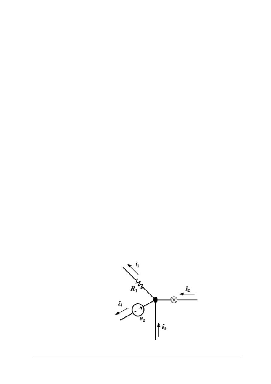
„Projekt współfinansowany ze środków Europejskiego Funduszu Społecznego”
37
across
capacitance
capacitor
chain
charge buildup
charge density
circuit
current-coupled
disperse
junction rule
Kirchhoff's
Current Law
magnitude
Ohm's Law
parallel circuit
polarities
potential
difference
reciprocal
repulsive
rungs
Series circuit
single path
sum of the
reciprocals
total resistance
3) If two or more circuit components are connected end to end like
a daisy chain, it is said they are connected in series. A series circuit is
a single path for electric current through all of its components.
If two or more circuit components are connected like the rungs of
a ladder it is said they are connected in parallel. A parallel circuit is
a different path for current through each of its components. A parallel
circuit provides the same voltage across all its components.
Series circuits are sometimes called current-coupled or daisy chain-
coupled. The current that flows in a series circuit has to flow through
every component in the circuit. Therefore, all of the components in
a series connection carry the same current. To find the total resistance of
all the components, add the individual resistances of each component:
Inductors follow the same law, in that the total inductance of non-
coupled inductors in series is equal to the sum of their individual
inductances:
Capacitors follow a different law. The total capacitance of capacitors in
series is equal to the reciprocal of the sum of the reciprocals of their
individual capacitances:
If two or more components are connected in parallel they have the same
potential difference (voltage) across their ends. The potential differences
across the components are the same in magnitude, and they also have
identical polarities. Hence, the same voltage is applicable to all circuit
components connected in parallel. The total current “I” is the sum of the
currents through the individual components, in accordance with
Kirchhoff's Current Law. The current in each individual resistor is found
by Ohm's Law. This law is also called Kirchhoff's first law, Kirchhoff's
point rule, Kirchhoff's junction rule, and Kirchhoff's first rule.
The principle of conservation of electric charge implies that:
At any point in an electrical circuit where charge density is not changing
in time, the sum of currents flowing towards that point is equal to the
sum of currents flowing away from that point.
A charge density changing in time would mean the accumulation of a net
positive or negative charge, which typically cannot happen to any
significant degree because of the strength of electrostatic forces: the
charge buildup would cause repulsive forces to disperse the charges.
Rys.9. Kirchhoff's junction rule [14]
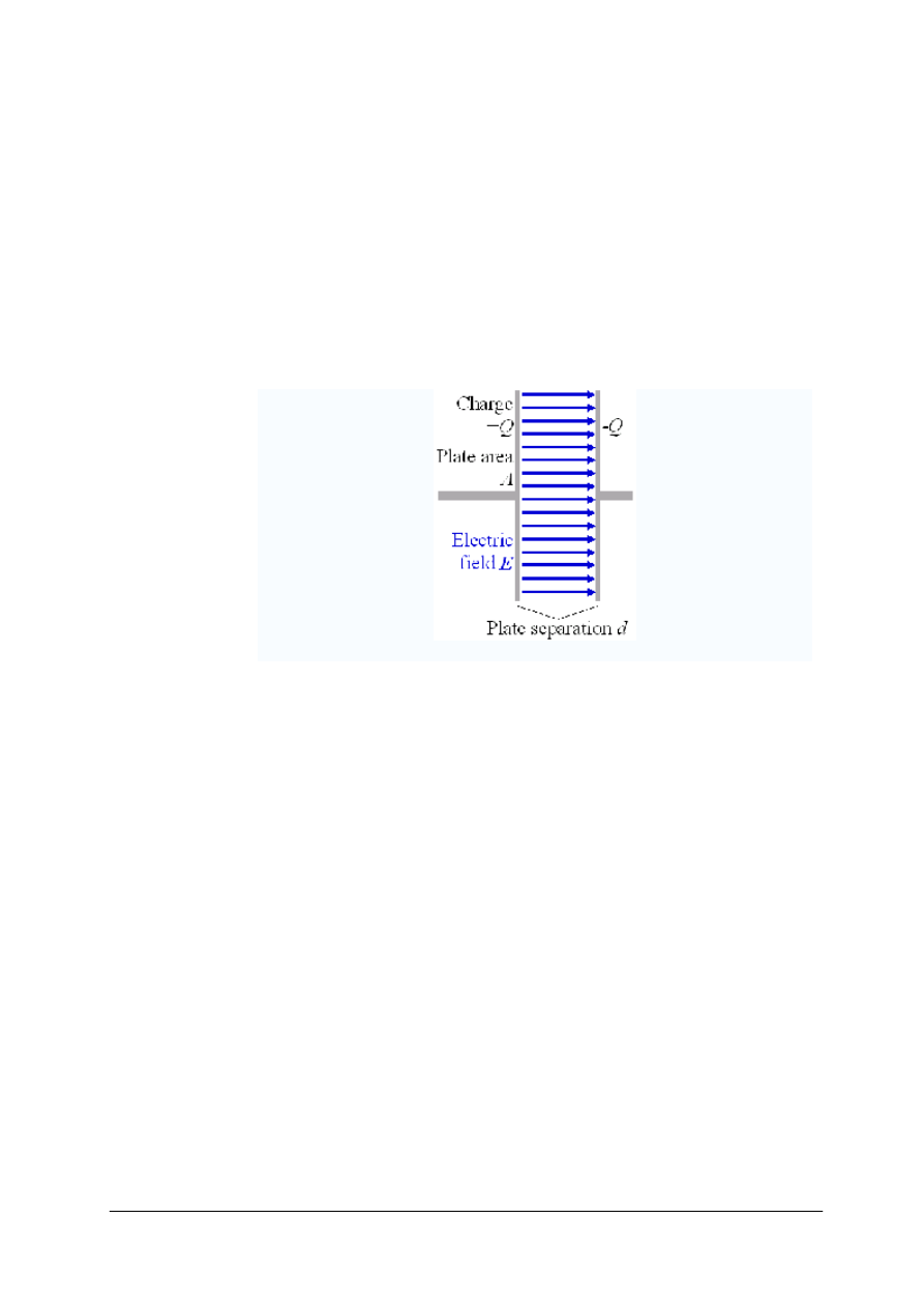
„Projekt współfinansowany ze środków Europejskiego Funduszu Społecznego”
38
capacitor
charging
condensers
differentiate
electric field
electrical circuit
electronic device
energy-storage
equal
filters
high-frequency
low-frequency
magnitude
opposite polarity
plates
referred to as
store energy
4) A capacitor is an electrical/electronic device that can store energy in
the electric field between a pair of conductors (called "plates"). The
process of storing energy in the capacitor is known as "charging", and
involves electric charges of equal magnitude, but opposite polarity,
building up on each plate.
Capacitors are often used in electrical circuit and electronic circuits as
energy-storage devices. They can also be used to differentiate between
high-frequency and low-frequency signals. This property makes them
useful in electronic filters.
Capacitors are occasionally referred to as condensers. This is considered
an antiquated term in English, but most other languages use an
equivalent, like "Kondensator" in German.
Rys.10. Capacitor [15]
airborne
area navigation
communication
direction finder
DME
glide slope
ILS instrument
landing system
marker beacon
navigation
navigational aids
omnidirectional
receiver
transmission
transmitter
5) Communications and navigation are the two major functions of
airborne radio. Communication systems primarily involve voice
transmission and reception between aircraft or aircraft and ground
stations. Radios are used in aircraft as navigational aids in a number of
applications. They range from a simple radio direction finder to
navigational systems which use computers and other advanced electronic
techniques to automatically solve the navigational problems for an entire
flight. Marker beacon receivers, instrument landing systems (involving
radio signals for glide slope and direction), distance measuring
equipment, radar, area navigation systems, and omnidirectional radio
receivers are but a few basic applications of airborne radio navigation
systems available for installation and use in aircraft.
AM
amplitude
modulation
circuitry
device
fluctuate
FM frequency
modulation
housing
interference
6) A transceiver is a device that has both a transmitter and a receiver
which are combined and share common circuitry or a single housing. If
no circuitry is common between transmit and receive functions, the
device is a transmitter-receiver. The term originated in the early 1920s.
Technically, transceivers must combine a significant amount of the
transmitter and receiver handling circuitry. Similar devices include
transponders, transverters, and repeaters.
AM broadcast radio sends music and voice in the Medium Frequency
(MF—0.300 MHz to 3 MHz) radio spectrum. AM radio uses amplitude

„Projekt współfinansowany ze środków Europejskiego Funduszu Społecznego”
39
microphone
modulate
multiple
proportional
repeaters
static
subject to
transceiver
transducer
transmitter-
receiver
transponders
transverters
variation
modulation, in which the amplitude of the transmitted signal is made
proportional to the sound amplitude captured (transduced) by the
microphone while the transmitted frequency remains unchanged.
FM broadcast radio sends music and voice with higher fidelity than AM
radio. In frequency modulation, amplitude variation at the microphone
causes the transmitter frequency to fluctuate. Because the audio signal
modulates the frequency and not the amplitude, an FM signal is not
subject to static and interference in the same way as AM signals. FM is
transmitted in the Very High Frequency (VHF—30 MHz to 300 MHz)
radio spectrum. Aviation voice radios use VHF AM. AM is used so that
multiple stations on the same channel can be received. (Use of FM would
result in stronger stations blocking out reception of weaker stations due
to FM's capture effect).
satellite
navigation
spherical shell
tangent
time-of-flight
7) All satellite navigation systems use satellites with precision clocks.
The satellite transmits its position, and the time of the transmission. The
receiver listens to four satellites, and can figure its position as being on
a line that is tangent to a spherical shell around each satellite, determined
by the time-of-flight of the radio signals from the satellite. A computer in
the receiver does the math.
beam
bouncing
continually
directional
in sound
master signal
omnidirectional
phase
phase
range
surface
take a fix
Timed signal
VOR
8) Major advance in "beam based" navigation system was the use of two
signals that varied not in sound, but in phase. In these systems, known as
VHF omnidirectional range, or VOR, a single master signal is sent out
continually from the station, and a highly directional second signal is sent
out that varies in phase 30 times a second compared to the master. This
signal is timed so that the phase varies as the secondary antenna spins,
such that when the antenna is 90 degrees from north, the signal is 90
degrees out of phase of the master. By comparing the phase of the
secondary signal to the master, the angle can be determined without any
physical motion in the receiver. This angle is then displayed in the
cockpit of the aircraft, and can be used to take a fix just like the earlier
RDF systems, although it is, in theory, easier to use and more accurate.
Radar (Radio Detection And Ranging) detects objects at a distance by
bouncing radio waves off them. The delay caused by the echo measures
the distance. The direction of the beam determines the direction of the
reflection. The polarization and frequency of the return can sense the
type of surface.
colocated
delay
Distance
Measuring
Equipment
DME
enroute
fixed duration
output
peak pulse
propagation
pulse
separation
9) Distance Measuring Equipment (DME) is a transponder-based radio
navigation technology that measures distance by timing the propagation
delay of VHF or UHF radio signals. Aircraft use DME to determine their
distance from a land-based transponder by sending and receiving pulse
pairs - two pulses of fixed duration and separation. The ground stations
are typically colocated with VORs. A typical DME ground transponder
system for enroute or terminal navigation will have a 1 kW peak pulse
output on the assigned UHF channel.
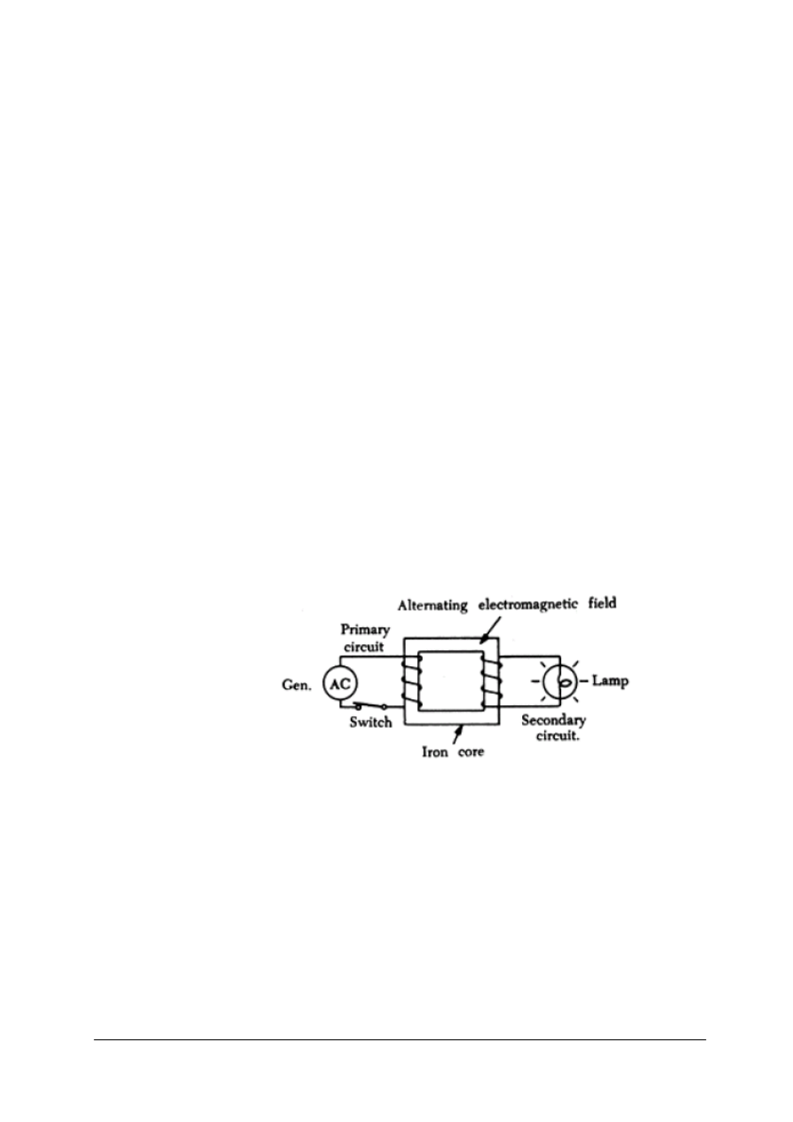
„Projekt współfinansowany ze środków Europejskiego Funduszu Społecznego”
40
approach system
comparison
guidance
ILS instrument
landing system
lighting arrays
modulation depth
runway
sub-systems
10) The Instrument Landing System (ILS) is a ground-based instrument
approach system which provides precise guidance to an aircraft
approaching a runway, using a combination of radio signals and, in many
cases, high-intensity lighting arrays to enable a safe landing during
instrument meteorological conditions (IMC), such as low ceilings or
reduced visibility due to fog, rain, or blowing snow. An ILS consists of
two independent sub-systems, one providing lateral guidance (Localizer),
the other vertical guidance (Glideslope or Glide Path) to aircraft
approaching a runway. Aircraft guidance is provided by the ILS receivers
in the aircraft by performing a modulation depth comparison.
alternating
altimeter
carrier frequency
conductor
core
electromagnetic
field
electromagnetic
spectrum
extinguishes
frequency bands
illuminate
indicator
marker beacons
reflect
secondary circuit
transformer
wireless
11) Radio altimeters are used to measure the distance from the aircraft to
the ground. This is accomplished by transmitting radio frequency energy
to the ground and receiving the reflected energy at the aircraft. Most
modern day altimeters are pulse type and the altitude is determined by
measuring the time required for the transmitted pulse to hit the ground
and return. The indicating instrument will indicate the true altitude of the
aircraft, which is its height above water, mountains, buildings, or other
objects on the surface of the earth.
On most installations marker beacons operating at a carrier frequency of
75 MHz are provided. When the transmission from a marker beacon is
received it activates an indicator on the pilot's instrument panel and the
tone of the beacon is audible to the pilot.
The principle of radio communication can be illustrated by using a
simple transformer. As shown in figure 11, closing the switch in the
primary circuit causes the lamp in the secondary circuit to be illuminated.
Opening the switch extinguishes the light.
Rys.11. Transformer [4]
There is no direct connection between the primary and secondary
circuits. The energy that illuminates the light is transmitted by an
alternating electromagnetic field in the core of the transformer. This is
a simple form of wireless control of one circuit (the secondary) by
another circuit (the primary). The basic concept of radio communications
involves the transmission and reception of electromagnetic (radio) energy
waves through space. Alternating current passing through a conductor
creates electromagnetic fields around the conductor.
The radio frequency portion of the electromagnetic spectrum extends
from approximately 30 kHz (kilohertz) to 30,000 MHz (Megahertz).
As a matter of convenience, this part of the spectrum is divided into
frequency bands. Each band or frequency range produces different
effects in transmission.
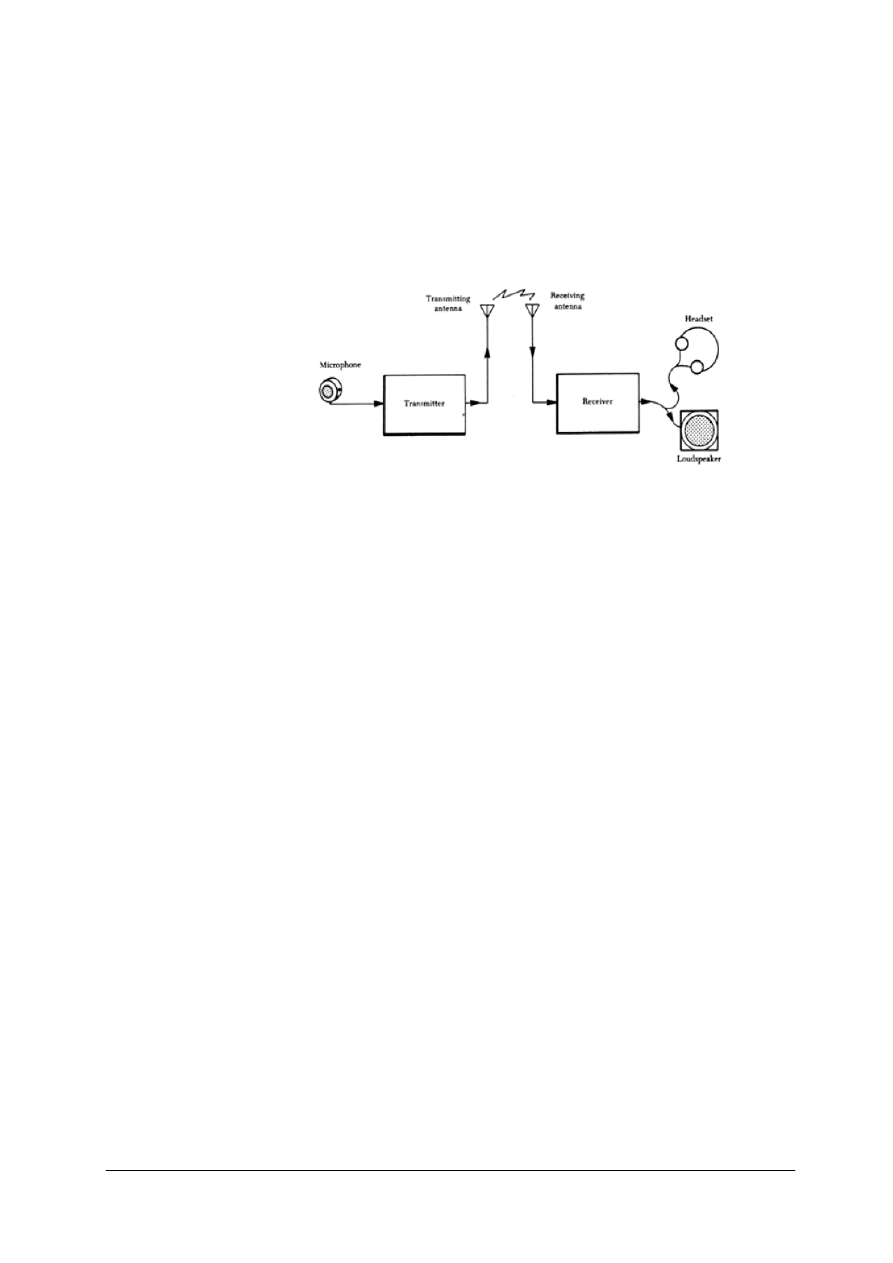
„Projekt współfinansowany ze środków Europejskiego Funduszu Społecznego”
41
amplify
circuit
frequency doubler
generator
intelligence
modulator
multiplier
oscillator
subharmonic
waves
12) A transmitter may be considered as a generator which changes
electrical power into radio waves. A transmitter must perform these
functions: (1) Generate a RF (radio frequency) signal, (2) amplify the RF
signal, and (3) provide a means of placing intelligence on the signal.
The transmitter contains an oscillator circuit to generate the RF signal (or
a subharmonic of the transmitter frequency, if frequency doublers or
multipliers are used) and amplifier circuits to increase the output of the
oscillator to the power level required for proper operation.
Rys.12. Transmitter and receiver set. [4]
The voice (audio) intelligence is added to the RF signal by a special
circuit called the modulator. The modulator uses the audio signal to vary
the amplitude or frequency of the RF signal. If the amplitude is varied,
the process is called amplitude modulation or AM. If the frequency is
varied, the process is known as frequency modulation or FM.
ac signal
convert
current
demodulator
detector
discriminator
electrical circuit
electromagnetic
radiate
select
sensitive
13) The communications receiver must select radio frequency signals and
convert the intelligence contained on these signals into a usable form;
either audible signals for communication and audible or visual signal for
navigation. Radio waves of many frequencies are present in the air.
A receiver must be able to select the desired frequency from all those
present and amplify the small ac signal voltage. The receiver contains
a demodulator circuit to remove the intelligence. If the demodulator
circuit is sensitive to amplitude changes, it is used in AM sets and called
a detector. A demodulator circuit that is sensitive to frequency changes is
used for FM reception and is known as a discriminator.
An antenna is a special type of electrical circuit designed to radiate and
receive electromagnetic energy. As mentioned previously, a transmitting
antenna is a conductor which radiates electromagnetic waves when
a radio frequency current is passed through it.
acoustical
converter
diaphragm
instantaneous
microphone
pressure waves
14) A microphone is essentially an energy converter that changes
acoustical (sound) energy into corresponding electrical energy. When
spoken into a microphone, the audio pressure waves generated strike the
diaphragm of the microphone causing it to move in and out in accordance
with the instantaneous pressure delivered to it.
AC/ DC voltage
alternating current
current
direct current
dynamotors
15) The power supply is a component that furnishes the correct voltages
and current needed to operate the communication equipment. The power
supply can be a separate component or it may be contained within the
equipment it supplies. Electromechanical devices used as electronic
power supplies include dynamotors and inverters. The dynamotor

„Projekt współfinansowany ze środków Europejskiego Funduszu Społecznego”
42
electromechanical
furnishes
generator
inverters
motor
multivibrator
periodically
power supply
semiconductor
solid state
voltage
performs the dual functions of motor and generator, changing the
relatively low voltage of the aircraft electrical system into a much higher
value. The multivibrator is another type of voltage supply used to obtain
a high ac or dc voltage from a comparatively low dc voltage.
In many aircraft, the primary source of electric power is direct current.
An inverter is used to supply the required alternating current. Common
aircraft inverters consist of a dc motor driving an ac generator. Static or
solid state inverters are replacing the electromechanical inverters in many
applications. Static inverters have no moving parts, but use
semiconductor devices and circuits that periodically pulse dc current
through the primary of a transformer to obtain an ac output from the
secondary.
4.4.2. Pytania sprawdzające
Odpowiadając na pytania, sprawdzisz, czy jesteś przygotowany do wykonania ćwiczeń.
1. What are the four types of materials according to their resistance?
2. What is a PCB made up of?
3. What is the total resistance in a series circuit?
4. What is the total capacitance in a series circuit?
5. What is the total resistance in a parallel circuit?
6. What is the total capacitance in a parallel circuit?
7. What does Kirchhoff's first law state?
8. What is a capacitor made up of?
9. What are radios used for in an aircraft?
10. What does a transceiver stand for?
11. Why do aviation voice radios use amplitude modulation?
12. How many signals does the VOR send to the aircraft?
13. What is a DME used for?
14. What does an ILS system consist of?
15. What is the radio altimeter used for?
16. What are the main components of a transformer?
17. How does a FM radio work?
18. What is a demodulator circuit used for?
19. What is the movable part of a microphone called?
20. What is a “solid state device” referred to?
4.4.3. Ćwiczenia
Ćwiczenie 1
Korzystając z oferty sklepu internetowego – http://www.electronicplus.com/ – sprawdź
cenę elementów niezbędnych do naprawy 50
prostowników prądu stałego oraz koszty wysyłki
zamówienia.
Sposób wykonania ćwiczenia
Aby wykonać ćwiczenie, powinieneś:
1) sprawdzić w słowniku znaczenie nazw zamawianych elementów,
2) wyszukać na podanej stronie internetowej wymienione części, sprawdzić ich cenę, oraz
nacisnąć ikonę „dodaj do koszyka”,
3) sprawdzić cenę zamówienia, oraz koszty wysyłki po wprowadzeniu opcji najszybszej
wysyłki, kraju przeznaczenia, kodu pocztowego.
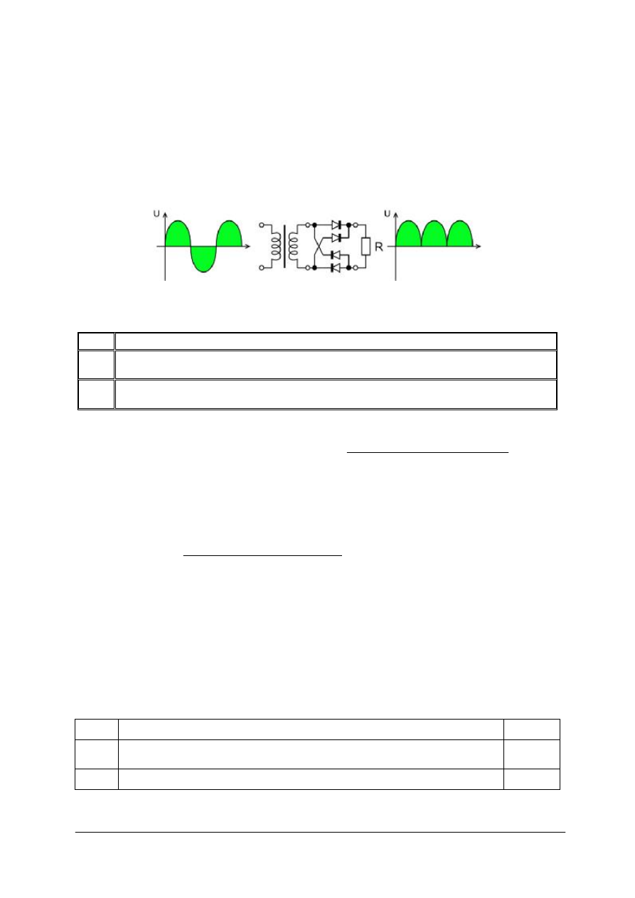
„Projekt współfinansowany ze środków Europejskiego Funduszu Społecznego”
43
Wyposażenie stanowiska pracy:
–
komputer z dostępem do Internetu,
–
poradnik dla ucznia, słownik techniczny.
Parametry prostownika.
Napięcie zasilania – 110V.
Napięcie wyjściowe prostownika – 9V-12V.
Natężenie prądu na wyjściu - 1A.
Rys. do ćwiczenia 1. Prostownik prądu stałego [16]
Wykaz podzespołów do zamówienia po 50 sztuk.
Part #
Description
167
2 AMP 200 VOLT FULL WAVE BRIDGE (CONVERTS AC VOLTAGE TO DC VOLTAGE) -
FLAT PACKAGE WITH 4 SOLDER LEADS
P-6434
SECONDARY RATING: 12 VOLTS AC @ 2.5 AMPS TRANSFORMER-SIZE: 4.00" x 3.25" x
3.00"
Ćwiczenie 2
Korzystając z oferty sklepu internetowego – http://www.electronicplus.com/ - znajdź
dane teleadresowe niezbędne do prowadzenia korespondencji z firmą „Electronicplus”,
wysłania poczty e-mail, faksu oraz złożenia zamówienia drogą telefoniczną.
Sposób wykonania ćwiczenia
Aby wykonać ćwiczenie, powinieneś:
1) otworzyć stronę http://www.electronicplus.com,
2) przeanalizować informacje zawarte na stronie,
3) znaleźć i zapisać dane teleadresowe oraz godziny pracy firmy „Electronicplus”,
Wyposażenie stanowiska pracy:
–
komputer z dostępem do Internetu,
–
poradnik dla ucznia.
Ćwiczenie 3
Korzystając z danych teleadresowych uzyskanych w wyniku wykonania ćwiczeniu 2,
napisz faks z zamówieniem na 50 sztuk poniższych podzespołów.
Part #
Description
Quantity
167
2 AMP 200 VOLT FULL WAVE BRIDGE (CONVERTS AC VOLTAGE TO DC
VOLTAGE)-FLAT PACKAGE WITH 4 SOLDER LEADS
50
P-6434
SECONDARY RATING: 12 VOLTS AC @ 2.5 AMPS TRANSFORMER-SIZE:
50

„Projekt współfinansowany ze środków Europejskiego Funduszu Społecznego”
44
Sposób wykonania ćwiczenia
Aby wykonać ćwiczenie, powinieneś:
1) wyszukać w słowniku, Internecie wzór listu oficjalnego,
2) napisać list zgodnie ze wzorem,
3) użyć stylu “blok”, w którym wszystkie akapity zaczynają sie od lewego brzegu strony,
4) podać pełną nazwę i dane teleadresowe firmy zamawiajacej,
5) podać nazwę i dane firmy realizującej zamówienie,
6) użyć zwrotu do adresata ”Dear Sir/Madam”,
7) rozpocząć treść zamówienia zwrotem “I would like to order goods listed below”
8) wypisać zamawiane części w formie tabelarycznej zawierającej numer katalogowy
części, krótki opis, ilośc zamawianych sztuk,
9) poniżej zamówienia podać obowiązkowo “Shipping address:”
10) podać także “Shipping method” jeżeli masz jakiś wybór np. ”UPS Worldwide Saver”
11) użyć oryginalnego druku zamówień jeśli firma realizujaca zamówienie taki udostępnia,
12) zamówienie napisać na komputerze, gdyż pismo odręczne jest interpretowane różnie
w poszczególnych krajach. Napisana w Polsce odręcznie cyfra 1 jest prawie zawsze
traktowana w USA jako cyfra 7.
Wyposażenie stanowiska pracy:
–
komputer z dostępem do Internetu,
–
poradnik dla ucznia, słownik języka angielskiego.
Ćwiczenie 4
Korzystając z danych teleadresowych uzyskanych w wyniku wykonania ćwiczeniu 2 oraz
informacji uzyskanych w
wyniku
wykonania
ćwiczenia
3, dokonaj zamówienia telefonicznego
poniższych podzespołów zgodnie z tabelą. Poproś o jak najszybszą realizację następującego
zamówienia.
Part #
Description
Qty.
SOL820
0
12 VDC MECHANICAL SOLENOID WITH 5/16" DIAMETER METAL ROD THAT
IS PULLED IN UPON APPLICATION OF VOLTAGE-SIZE: 7/8" WIDE x 1-1/8"
LONG x 1-1/8" HIGH
10
SAS-30A
86 DEGREES FAHRENHEIT (30 DEGREES CENTIGRADE) FLAT DISC
THERMOSTAT (15 AMPS MAXIMUM)-(CIRCUIT CLOSES AT DESCRIBED
TEMPERATURE)-WILL AUTOMATICALLY RESET ONCE ALLOWED TO
COOL
8
RS3-
1A10-52
100 to 280 VOLTS AC COIL INPUT WITH 24 to 330 VOLTS AC @ 10 AMPS
SWITCHING CAPABILITY SOLID STATE RELAY-NORMALLY OPEN SINGLE
POLE SINGLE THROW (S.P.S.T.) CONTACT-SIZE: 2.25" LONG x 1.75" WIDE
x .95" HIGH
31
5802
3 AMPS @ 200 VOLTS GENERAL PURPOSE RECTIFIER-AXIAL SOLDER
LEADS-DO-27 CASE
12
Sposób wykonania ćwiczenia
Aby wykonać ćwiczenie, powinieneś:
1) przeanalizować dane zawarte w tabeli,
2) wykorzystać informacje uzyskane podczas realizacji ćwiczeń 2 i 3,
3) wykonać „symulowaną” rozmowę telefoniczną.
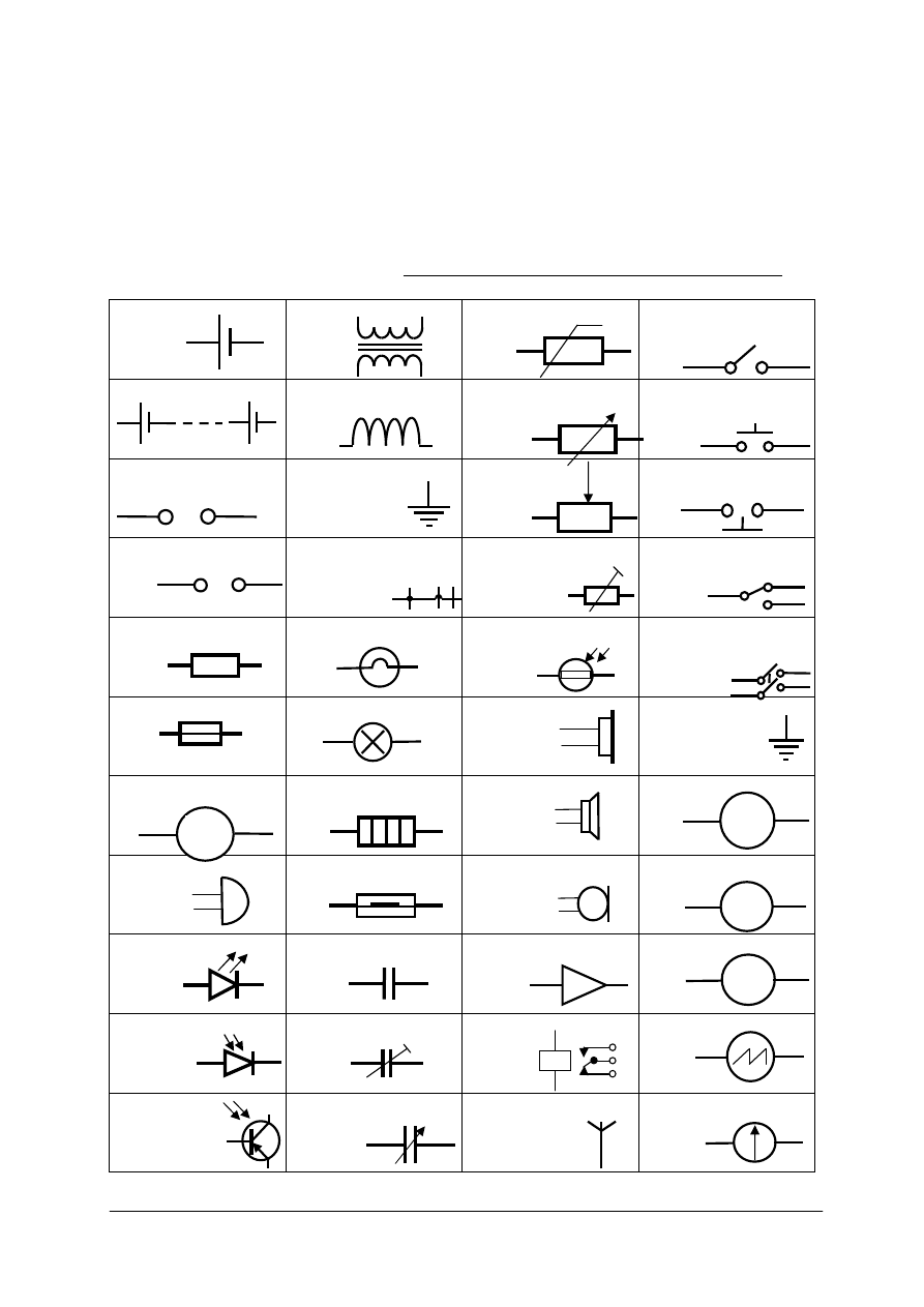
„Projekt współfinansowany ze środków Europejskiego Funduszu Społecznego”
45
Wyposażenie stanowiska pracy:
–
poradnik dla ucznia,
–
słownik języka angielskiego.
Ćwiczenie 5
Dokonaj tłumaczenia nazw podzespołów elektrycznych i elektronicznych przedstawionych
na rysunku do ćwiczenia 5.
Skorzystaj ze słownika technicznego oraz z informacji
przedstawionych na stronie internetowej http://www.technologystudent.com/elec1/elecex.htm
cell
transformer, iron core
thermistor
on-off switch
battery
coil, inductor, solenoid rheostat
push switch
DC power supply
ground
potentiometer
push-to-break switch
AC power supply
wires joined,
not joined,
not joined
variable resistor
single pole double
throw switch
resistor
lamp (lighting)
LDR – light dependent
resistor
double pole single
throw switch
fuse
Lamp (indicator)
earphone
earth, ground
motor
heater
speaker
voltmeter
bell
reed switch
microphone
ohmmeter
LED
capacitor
amplifier
ammeter
photodiode
trimmer capacitor
relay
oscilloscope
phototransistor
variable capacitor
aerial
galvanometer
Rys. do ćwiczenia 5. Symbole podzespołów elektronicznych.
+ -
~
M
A
V
Ω

„Projekt współfinansowany ze środków Europejskiego Funduszu Społecznego”
46
Sposób wykonania ćwiczenia
Aby wykonać ćwiczenie, powinieneś:
1) przeanalizować rysunek,
2) znaleźć wskazaną stronę internetową,
3) porównać symbole i dołączone do nich rysunki
4) wypisać tłumaczenia nazw poszczególnych symboli.
Wyposażenie stanowiska pracy:
–
poradnik dla ucznia,
–
słownik języka angielskiego.
4.4.4. Sprawdzian postępów
Czy potrafisz:
Tak
Nie
1) odszukać w katalogu, lub na stronie internetowej wskazaną część
elektroniczną?
2) napisać fax, lub e-mail w formacie listu oficjalnego?
3) wykonać rozmowę telefoniczną w celu zamówienia brakujących
części?
4) nazwać podstawowe podzespoły elektroniczne?
5) scharakteryzować właściwości obwodu szeregowego i równoległego?
6) nazwać główne podzespoły nadajnika i odbiornika radiowego?
7) nazwać główne elementy systemu lądowania ILS?
8) opisać zasadę pracy radiowysokościomierza?

„Projekt współfinansowany ze środków Europejskiego Funduszu Społecznego”
47
4.5. Podstawowe operacje obróbki ręcznej i mechanicznej
4.5.1. Materiał nauczania
acetylene
adhesive bonding
alloys
arc
blows
bolting
brazing
chrome
equipment rig
extinguisher
flame
flint lighter
fusing
goggles
hose
hydrogen
joined
mild carbon steel
mixing head
molten
molten
molybdenum
oxyacetylene
oxygen
plastic
portable
riveting
soldering
stationary
tips
torch
union
welding
wrench
1) Metals can be joined by mechanical means (bolting or riveting, or by
welding, brazing, soldering or adhesive bonding). All of these methods
are used in aircraft construction. This chapter will discuss the methods
used to join metals by welding, brazing, and soldering.
Welding is the process of joining metal by fusing the materials while
they are in a plastic or molten state. There are three general types of
welding: (1) Gas, (2) electric arc, and (3) electric resistance welding.
Each of these types of welding has several variations which are
used in aircraft construction.
Gas welding is accomplished by heating the ends or edges of metal parts
to a molten state with a high temperature flame. This flame is produced
with a torch burning a special gas such as acetylene or hydrogen with
pure oxygen. The metals, when in a molten state, flow together to form
a union without the application of mechanical pressure or blows.
Aircraft parts fabricated from chrome-molybdenum or mild carbon steel
are often gas welded. There are two types of gas welding in common use:
(1) Oxyacetylene and (2) oxyhydrogen. Nearly all gas welding in aircraft
construction is done with an oxyacetylene flame, although some
manufacturers prefer an oxyhydrogen flame for welding aluminum
alloys.
Oxyacetylene welding equipment may be either stationary or portable.
A portale equipment rig consists of the following:
(1) Two cylinders, one containing oxygen and one acetylene.
(2) Acetylene and oxygen pressure regulators, complete with pressure
gauges and connections.
(3) A welding torch, with a mixing head, extra tips and connections.
(4) Two lengths of colored hose, with adapter connections for the torch
and regulators.
(5) A special wrench.
(6) A pair of welding goggles.
(7) A flint lighter.
(8) A fire extinguisher.
adjacent
blow
bore
build-up
bulge
bump
cavity
chattering
chisel
contour
depressions
discoloration
displacement
excessive
2) Types of damage and defects which may be observed on parts of this
assembly are defined as follows:
BRINELLING - Occurrence of shallow, spherical depressions in
a surface, usually produced by a part having a small radius in contact
with the surface under high load.
BURNISHING - Polishing of one surface by sliding contact with
a smooth, harder surface. Usually no displacement nor removal of metal.
BURR - A small, thin section of metal extending beyond a regular
surface, usually located at a corner or on the edge of a bore or hole.
CORROSION - Loss of metal from the surface by chemical or
electrochemical action. The corrosion products generally are easily
removed by mechanical means. Iron rust is an example of corrosion.
CRACK - A physical separation of two adjacent portions of metal,

„Projekt współfinansowany ze środków Europejskiego Funduszu Społecznego”
48
excessive
extend
extraneous
few thousandths
forging
friction
glancing
grit
grooves
high load
hole
iron rust
polishing
radius
rolling
saw blade
separation
shallow
sliding
slightly upset
spherical
stress
tear
evidenced by a fine or thin line across the surface, caused by excessive
stress at that point. It may extend inward from the surface from a few
thousandths inch to completely through the section thickness.
CUT - Loss of metal, usually to an appreciable depth over a relatively
long and narrow area, by mechanical means, as would occur with the use
of a saw blade, chisel or sharp-edged stone striking a glancing blow.
DENT - Indentation in a metal surface produced by an object striking
with force. The surface surrounding the indentation will usually be
slightly upset.
EROSION - Loss of metal from the surface by mechanical action of
foreign objects. Such as grit or fine sand. The eroded area will be rough
and may be lined in the direction in which the foreign material moved
relative to the surface.
CHATTERING - Breakdown or deterioration of metal surface by
vibratory or "chattering" action. Usually no loss of metal or cracking of
surface but generally showing similar appearance.
GALLING - Breakdown (or build-up) of metal surfaces due to excessive
friction between two parts having relative motion. Particles of the softer
metal are torn loose and "welded" to the harder.
GOUGE - Grooves in, or breakdown of, a metal surface from contact
with foreign material under heavy pressure. Usually indicates metal loss
but may be largely displacement of material.
INCLUSION - Presence of foreign or extraneous material wholly within
a portion of metal. Such material is introduced during the manufacture of
rod, bar or tubing by rolling or forging.
NICK - Local break or notch on edge. Usually displacement of metal
rather than loss.
PITTING - Sharp, localized breakdown (small, deep cavity) of metal
surface, usually with defined edges.
SCRATCH - Slight tear or break in metal surface from light, momentary
contact by foreign material.
SCORE - Deeper (than scratch) tear or break in metal surface from
contact under pressure. May show discoloration from temperature
produced by friction.
STAIN - A change in color, locally causing a noticeably different
appearance from the surrounding area.
UPSETTING - A displacement of material beyond the normal contour or
surface (a local bulge or bump). Usually indicates no metal loss.
airframe
anvil
ash
bench vise
cast iron bench
plate
chiseling
clamping
crimped
deface
dolly
flanges
hammered
3) Sheet metal is often formed or finished (planished) over variously
shaped anvils called dollies and stakes. These are used for forming small,
oddshaped parts, or for putting on finishing touches for which a large
machine may not be suited. Dollies are meant to be held in the hand,
whereas stakes are designed to be supported by a flat cast iron bench
plate fastened to the workbench.
Most stakes have machined, polished surfaces which have been
hardened. Do not use stakes to back up material when chiseling, or when
using any similar cutting tool because this will deface the surface of the
stake and make it useless for finish work.
V-blocks made of hardwood are widely used in airframe metalwork for

„Projekt współfinansowany ze środków Europejskiego Funduszu Społecznego”
49
hardened
hardwood
machined
maple
metalwork
oddshaped
planish
sheet metal
shrinking
stake
stretching
workbench
shrinking and stretching metal, particularly angles and flanges. The size
of the block depends on the work being done and on personal preference.
Although any type of hardwood is suitable, maple and ash are
recommended for best results when working with aluminum alloys.
A shrinking block consists of two metal blocks and some device for
clamping them together. One block forms the base, and the other is cut
away to provide space where the crimped material can be hammered. The
legs of the upper jaw clamp the material to the base block on each side of
the crimp so that the material will not creep away but will remain
stationary while the crimp is hammered flat (being shrunk). This type of
crimping block is designed to be held in a bench vise.
Shrinking blocks can be made to fit any specific need. The basic form
and principle remain the same, even though the blocks may vary
considerably in size and shape.
bed
blade
crosshead
foot
held securely
holddown clamp
scale
shears
spring
squaring
treadle
4) Squaring shears provide a convenient means of cutting and squaring
metal. These shears consist of a stationary lower blade attached to a bed
and a movable upper blade attached to a crosshead. To make the cut, the
upper blade is moved down by placing the foot on the treadle and
pushing downward.
The shears are equipped with a spring which raises the blade and treadle
when the foot is removed. A scale, graduated in fractions of an inch, is
scribed on the bed. Two squaring fences, consisting of thick strips of
metal and used for squaring metal sheets, are placed on the bed, one on
the right side and one on the left. Each is placed so that it forms a 90°
angle with the blades.
Three distinctly different operations can be performed on the squaring
shears: (1) Cutting to a line, (2) squaring, and (3) multiple cutting to
a specific size. When cutting to a line, the sheet is placed on the bed of
the shears in front of the cutting blade with the cutting line directly even
with the cutting edge of the bed. The sheet is cut by stepping on the
treadle while the sheet is held securely in place by the holddown clamp.
Squaring requires several steps. First, one end of the sheet is squared
with an edge (the squaring fence is usually used on the edge). Then the
remaining edges are squared by holding one squared end of the sheet
against the squaring fence and making the cut, one edge at a time, until
all edges have been squared.
alignment
frame
hole
index pins
punch
radii
repair shop
rotate
synchronized
turrets
washer
5) The rotary punch is used in the airframe repair shop to punch holes in
metal parts. This machine can be used for cutting radii in corners, for
making washers, and for many other jobs where holes are required. The
machine is composed of two cylindrical turrets, one mounted over the
other and supported by the frame. Both turrets are synchronized so that
they rotate together, and index pins assure correct alignment at all times.
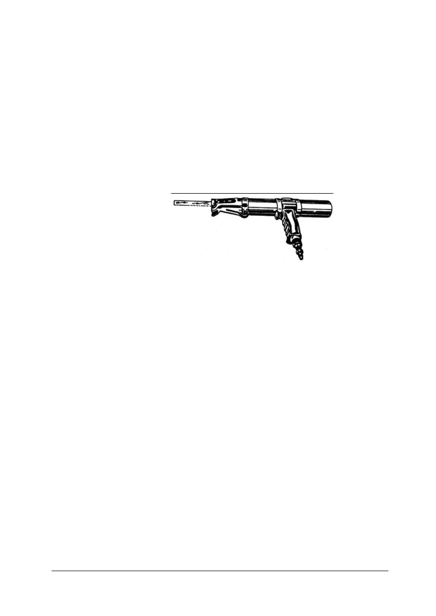
„Projekt współfinansowany ze środków Europejskiego Funduszu Społecznego”
50
100 psi
accuracy
air powered
blanking action
bolts
circular saw
diameter
die
drill press
drilling
feed lever
gun-type
hacksaw
head
light metal
nibblers
outside radius
portable
reciprocating saw
rectangular hole
rivets
starting hole
6) The electrically operated portable circular cutting Ketts saw uses
blades of various diameters. The head of this saw can be turned to any
desired angle, and is very handy for removing damaged sections on
a stringer. Advantages of a Ketts saw are:
(1) The ability to cut metal up to 3/16 inch thick.
(2) No starting hole is required.
(3) A cut can be started anywhere on a sheet of metal.
(4) The capability of cutting an inside or outside radius.
The portable, air powered reciprocating saw has a gun-type shape for
balancing and ease of handling and operates most effectively at an air
pressure of from 85 to 100 psi. The reciprocating saw uses a standard
hacksaw blade and can cut a 360° circle or a square or rectangular hole.
This saw is easy to handle and safe to use.
Rys.13. Reciprocating saw [4]
Stationary and portable nibblers are used to cut metal by a high speed
blanking action. The cutting or blanking action is caused by the lower die
moving up and down and meeting the upper stationary die. The shape of
the lower die permits small pieces of metal approximately
1/16 inch wide to be cut out.
One of the most common operations in airframe metalwork is that of
drilling holes for rivets and bolts. This operation is not difficult,
especially on light metal. Once the fundamentals of drills and their uses
are learned, a small portable power drill is usually the most practical
machine to use. However, there will be times when a drill press way
prove to be the better machine for the job.
The drill press is a precision machine used for drilling holes that require
a high degree of accuracy. It serves as an accurate means of locating and
maintaining the direction of a hole that is to be drilled and provides the
operator with a feed lever that makes the task of feeding the drill into the
work an easy one.
abrasive wheel
being ground
bits of abrasive
bits of metal
grinder
grinding wheel
pedestal grinder
tool rest
wet grinder
7) The term grinder applies to all forms of grinding machines. To be
specific, it is a machine having an abrasive wheel which removes excess
material while producing a suitable surface.
There are many kinds of grinding machines, but only those which are
helpful to the airframe mechanic will be discussed here.
The wet grinder, although similar to the pedestal grinder, differs from it
in that the wet grinder has a pump to supply a flow of water on a single
grinding wheel. The water reduces the heat produced by material being
ground against the wheel. It also washes away any bits of metal or
abrasive removed during the grinding operation. The water returns to
a tank and can be reused.

„Projekt współfinansowany ze środków Europejskiego Funduszu Społecznego”
51
Rys.14. Bench grinder [4]
bar
capacity
flanges
folder
gauge
hems
seams
8) The bar folder is designed for use in making bends or folds along
edges of sheets. This machine is best suited for folding small hems,
flanges, seams, and edges to be wired. Most bar folders have a capacity
for metal up to 22 gauge in thickness and 42 inches in length.
bumping
crimping
depression
die
dolly
form block
lead die
malleable metal
pounding
sandbag
seam
shaping
sink
stretched
thinner
to curve
wooden block
9) Shaping or forming malleable metal by hammering or pounding is
called bumping. During this process, the metal is supported by a dolly,
a sandbag, or a die. Each contains a depression into which hammered
portions of the metal can sink. Bumping can be done by hand or by
machine.
Folding, pleating, or corrugating a piece of sheet metal in a way that
shortens it is called crimping. Crimping is often used to make one end of
a piece of stovepipe slightly smaller so that one section may be slipped
into another. Turning down a flange on a seam is also called crimping.
Crimping one side of a straight piece of angle iron with crimping pliers
will cause it to curve.
Hammering a flat piece of metal will cause the material in that area to
become thinner. However, since the amount of metal will not have been
decreased, it will cover a greater area because the metal will have been
stretched.
During the shrinking process, material is forced or compressed into
a smaller area. The shrinking process is used when the length of a piece
of metal, especially on the inside of a bend, is to be reduced. Bumping on
a form block or female die and bumping on a sandbag are the two
common types practiced. In either method only one form is required,
a wooden block, lead die, or sandbag.
countersunk head
flathead
grip length
microshaver
pilot hole
predrilling
ream
riveting
roundhead
shop head
tolerance
twist drill
fuels
confined
fuel tanks
pressurized
10) Riveting. The type of head required for a particular job is determined
by its installation location. Where a smooth aerodynamic surface is
required, countersunk head rivets should be used. Universal head rivets
may be used in most other locations. If extra strength is required and
clearance permits, roundhead rivets may be used; if the necessary
clearance is not available, flathead rivets may be used.
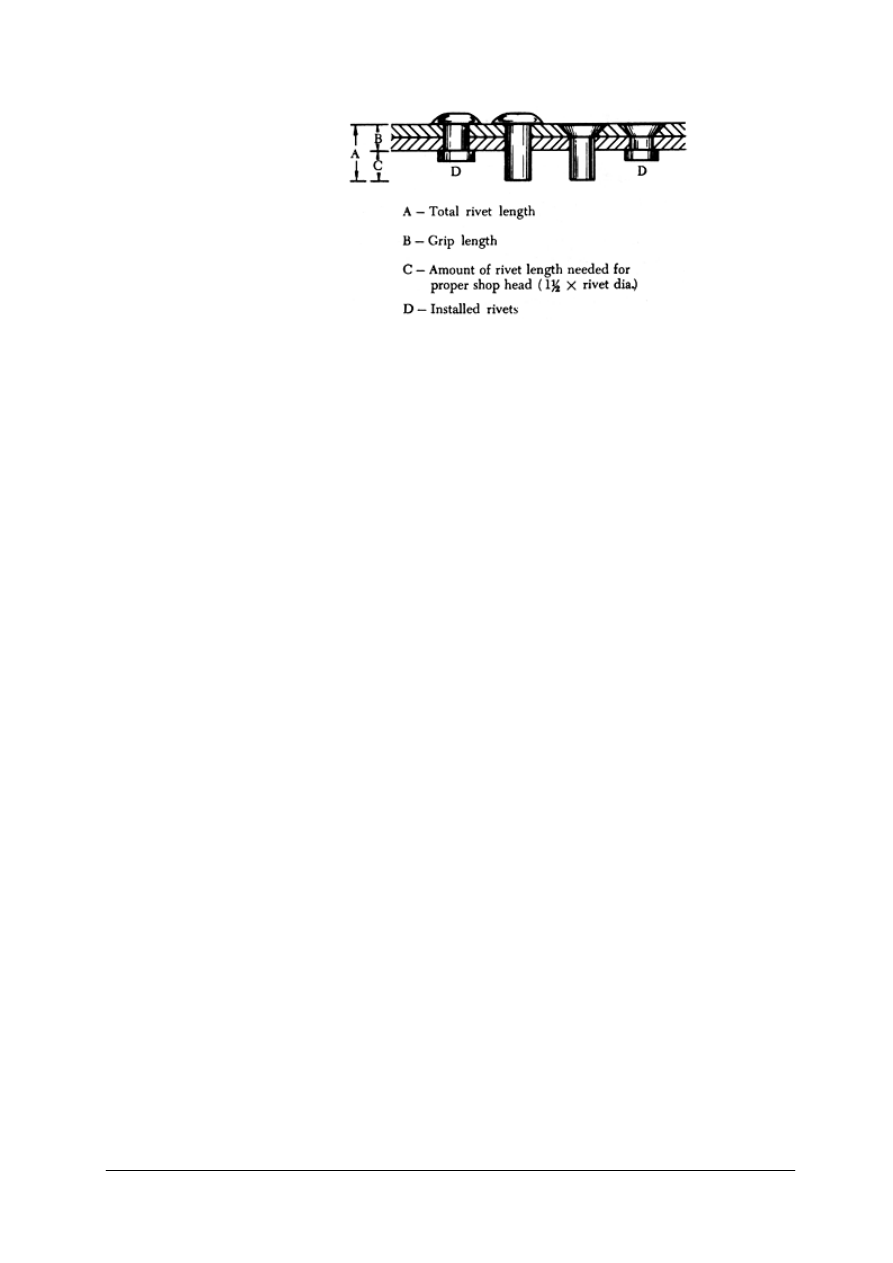
„Projekt współfinansowany ze środków Europejskiego Funduszu Społecznego”
52
compartment
airtight
riveted joint
sealing
sealant
smoothness
seams
undersize
Rys.15. Riveting. [4]
To make a rivet hole of the correct size, first drill a hole slightly
undersize. This is known as predrilling, and the hole is called a pilot hole.
Ream the pilot hole with a twist drill of the correct size to get the
required dimension.
Sometimes it is necessary to use a microshaver when making a repair
involving the use of countersunk rivets. If the smoothness of the material
(such as skin) requires that all countersunk rivets be driven within
a specific tolerance, a microshaver is used.
Various areas of airframe structures are sealed compartments where fuels
or air must be confined. Some of these areas contain fuel tanks; others
consist of pressurized compartments such as the cabin. Because it is
impossible to seal these areas completely airtight with a riveted joint
alone, a sealing compound or sealant must be used. Sealants are also used
to add aerodynamic smoothness to exposed surfaces such as seams and
joints in the wings and fuselage.
aging
aluminum
annealing
brittle
brittleness
ductile
extrusion
flexibility
furnace
furnace cooled
grain structure
hardened
internal strain
intricate shapes
lead
metal alloys
relieve
softness
solution
tempered
tin
workability
11) Steel is often harder than necessary and too brittle for most practical
uses when put under severe internal strain. To relieve such strain and
reduce brittleness, it is tempered after being hardened. This consists of
heating the steel in a furnace to a specified temperature and then cooling
it in air, oil, water, or a special solution. Temper condition refers to the
condition of metal or metal alloys with respect to hardness or toughness.
Rolling, hammering, or bending these alloys, or heat treating and aging
them, causes them to become tougher and harder. At times these alloys
become too hard for forming and have to be reheat treated or annealed.
Metals are annealed to relieve internal stresses, soften the metal, make it
more ductile, and refine the grain structure. Annealing consists of heating
the metal to a prescribed temperature, holding it there for a specified
length of time, and then cooling the metal back to room temperature. To
produce maximum softness, the metal must be cooled very slowly. Some
metals must be furnace cooled; others may be cooled in air.
The extrusion process involves the forcing of metal through an opening
in a die, thus causing the metal to take the shape of the die opening.
Some metals such as lead, tin, and aluminum may be extruded cold; but
generally metals are heated before the operation is begun.
The principal advantage of the extrusion process is its flexibility.
Aluminum, because of its workability and other favorable properties, can
be economically extruded to more intricate shapes and larger sizes than is
practicable with many other metals.

„Projekt współfinansowany ze środków Europejskiego Funduszu Społecznego”
53
Carburizing
casehardening
carbon
low carbon
interior
nitriding
definite properties
forgings
quenched
alleviates
cracking
distortion
core
12) Carburizing is a casehardening process in which carbon is added to
the surface of low carbon steel. Thus, a carburized steel has a high carbon
surface and a low carbon interior. When the carburized steel is heat
treated, the case is hardened while the core remains soft and tough.
Nitriding is unlike other casehardening processes in that, before nitriding,
the part is heat treated to produce definite physical properties. Thus, parts
are hardened and tempered before being nitrided. Most steels can be
nitrided, but special alloys are required for best results. These special
alloys contain aluminum as one of the alloying elements and are called
"nitralloys."
Large forgings and heavy sections can be quenched in hot or boiling
water. This type of quench minimizes distortion and alleviates cracking
which may be produced by the unequal temperatures obtained during the
quench.
4.5.2. Pytania sprawdzające
Odpowiadając na pytania, sprawdzisz, czy jesteś przygotowany do wykonania ćwiczeń.
1. What are the main methods of joining metals?
2. What is the most common gas welding method called?
3. Why is the defaced stake useless for finish work?
4. What are shrinking blocks used for?
5. What are squaring shears consist of?
6. What is the angle between two squared edges?
7. What does the rotary punch stand for?
8. Does a circular Ketts saw require a starting hole?
9. Does a reciprocating saw require a starting hole?
10. What is a portable nibbler used for?
11. What is a drill press used for?
12. Which machines use spinning abrasive wheel?
13. Is malleable metal suitable for making drill bits?
14. What type of rivet heads don’t extend above joined surface?
15. Which process makes metal less brittle?
16. Which process can increase metal strength?
17. What makes metal more ductile?
18. What metals can be extruded cold?
19. Can you name two casehardening processes?
4.5.3. Ćwiczenia
Ćwiczenie 1
Użyj poniższych wyrazów do uzupełnienia luk w tekście.
a) coalescence
d) soldering
g) electron beam
j) ultraviolet
b) metals
e) joint
h) gas flame
k) fumes
c) Welding
f) molten
i) bond
l) electric shock
1
)…………….. is a fabrication process that joins materials, usually
2
)……..……. or
thermoplastics, by causing
3
)……..……... This is often done by melting the workpieces and
adding a filler material to form a pool of
4
)………….. material (the weld puddle) that cools to
become a strong
5
)……..…., with pressure sometimes used in conjunction with heat, or by

„Projekt współfinansowany ze środków Europejskiego Funduszu Społecznego”
54
itself, to produce the weld. This is in contrast with
6
)……….…… and brazing, which involve
melting a lower-melting-point material between the workpieces to form a
7
)………. between
them, without melting the workpieces.
Arc welding.
Many different energy sources can be used for welding, including a
8
)…..………, an electric
arc, a laser, an
9
)………..…….., friction, and ultrasound. While often an industrial process,
welding can be done in many different environments, including open air, underwater and in
space. Regardless of location, however, welding remains dangerous, and precautions must be
taken to avoid burns,
10
)………..……., poisonous
11
)…………….., and overexposure to
12
)……….…. light.
1
2
3
4
5
6
7
8
9
10
11
12
Sposób wykonania ćwiczenia
Aby wykonać ćwiczenie, powinieneś:
1) przeanalizować tekst,
2) sprawdzić w słowniku technicznym znaczenie odpowiednich terminów,
3) wpisać w tabelę słówka zgodnie z wyborem.
Wyposażenie stanowiska pracy:
–
poradnik dla ucznia,
–
słownik techniczny języka angielskiego.
Ćwiczenie 2
Wykonaj prezentację ilustrującą typowe uszkodzenia elementów metalowych opisane we
fragmencie 2 materiału nauczania w rozdziale 4.5.1. Poradnika dla ucznia.
Sposób wykonania ćwiczenia
Aby wykonać ćwiczenie, powinieneś:
1) sprawdzić w słowniku technicznym znaczenie odpowiednich terminów,
2) otworzyć stronę internetową Google http://images.google.pl,
3) wyszukać fotografie i rysunki ilustrujące typowe uszkodzenia,
4) w programie do tworzenia prezentacji dokonać połączenia rysunków z opisami
zawartymi we fragmencie 2 materiału nauczania z rozdziału 4.5.1. Poradnika dla ucznia.
Wyposażenie stanowiska pracy:
–
komputer z dostępem do Internetu i programem Powerpoint lub Impress.
–
poradnik dla ucznia,
–
słownik techniczny języka angielskiego.

„Projekt współfinansowany ze środków Europejskiego Funduszu Społecznego”
55
4.5.4. Sprawdzian postępów
Czy potrafisz:
Tak
Nie
1) wymienić sposoby łączenia elementów metalowych używane
w lotnictwie?
2) rozpoznać typowe uszkodzenia elementów metalowych i ich
powierzchni?
3) nazwać narzędzia przeznaczone do obróbki mechanicznej?
4) nazwać procesy obróbki mechanicznej?
5) nazwać procesy obróbki cieplnej?
6) dokonać analizy czynności związanych z obróbką mechaniczną na
podstawie instrukcji w języku angielskim?

„Projekt współfinansowany ze środków Europejskiego Funduszu Społecznego”
56
4.6.
Podstawowe
słownictwo
używane
w
formularzach
i przepisach lotniczych
4.6.1. Materiał nauczania
Słownictwo zawarte w dokumentach, formularzach i przepisach posiada swoją specyfikę
w zależności od języka i systemu prawnego obowiązującego w danym państwie. O ile
tłumaczenie przepisów jest zadaniem dla prawnika, lub tłumacza przysięgłego to wypełnianie
formularzy i poświadczeń obsługi nie powinno sprawić ci trudności o ile wcześniej zapoznasz
się z ich treścią.
W poniższej tabeli przedstawiono słownictwo zawarte w formularzu 1 EASA wraz
z tłumaczeniem na język polski.
Tabela 1. Formularz 1 EASA
1. Approving Competent
Authority/Country
Właściwy organ zatwierdzający/państwo
2. EASA form 1
Formularz 1 EASA
3. Form Tracking Number
Numer formularza
4. Approved organization name and
address
Nazwa i adres zatwierdzonej organizacji
5. Work order/contract/invoice
Zlecenie/umowa/faktura
6. Item
Pozycja
7. Description
Wyszczególnienie
8. Part No
Numer Części
9. Eligibility (*)
Kwalifikowalność
10. Quantity
Liczba
11. Serial/Batch No
Numer serii/partii
12. Status/Work
Status/czynność
13. Remarks - part M section A subpart F
organization approval number:
Uwagi - Część M sekcja A podczęść F,
numer zatwierdzenia organizacji:
14. Certifies that the items identified above
were manufactured in conformity to:
Approved design data and are in
condition for safe operation
Non-approved design data specified in
block 13
Poświadcza się, że elementy podane powyżej
zostały wyprodukowane zgodnie z:
zatwierdzonymi danymi projektowymi i są
w stanie zapewniającym bezpieczne
użytkowanie
nie zatwierdzonymi danymi projektowymi
wymienionymi w polu 13
15. Part – 145.A.50 Release to Service
Other regulation specified in block 13
Certifies that unless otherwise specified in
block 13, the work identified in block 12
and described in block 13, was
accomplished in accordance with Part-145
and in respect to that work the items are
considered ready for release to service.
Część 145.A.50 Dopuszczenie do
użytkowania Inne przepisy
wyszczególnione w polu 13
Poświadcza się, że z wyjątkiem jak podano
w polu 13, prace wymienione w polu 12
zostały wykonane zgodnie z częścią 145
i w odniesieniu do tych czynności dane
części są uznane za zdatne do użytkowania.

„Projekt współfinansowany ze środków Europejskiego Funduszu Społecznego”
57
16. Authorised Signature
Autoryzowany podpis
17. Approval/ Authorization Number
Numer zatwierdzenia/ autoryzacji
18. Authorised signature
Autoryzowany podpis
19. Certificate/ approval Ref No
Numer zatwierdzenia/ certyfikatu
20. Name
Nazwisko
21. Date (d/m/y)
Data (d/m/r)
22. Name
Nazwisko
23. Date (d/m/y)
Data (d/m/r)
AUTHORISED RELEASE CERTIFICATE
– EASA FORM 1 (reverse side)
AUTORYZOWANE
POŚWIADCZENIE
PRODUKCJI/OBSŁUGI - FORMULARZ 1
EASA (rewers)
USER/INSTALLER RESPONSIBILITIES
OBOWIĄZKI
UŻYTKOWNIKA
/
MONTUJĄCEGO
NOTE:
UWAGA:
1. It is important to understand that the
existence of the document alone does not
automatically constitute authority to install
the part/ component/ assembly.
1. Należy pamiętać, że istnienie niniejszego
dokumentu nie stanowi upoważnienia do
zamontowania części/ podzespołu/zespołu.
2. Where the user/ installer works in
accordance with the national regulations of
an airworthiness authority different from the
airworthiness authority specified in block 1
it is essential that the user/ installer ensure
that his/her airworthiness authority accepts
parts/ components/assemblies from the
airworthiness authority specified in block 1.
2. Jeżeli użytkownik / montujący wykonuje
czynności
zgodnie
z
państwowymi
przepisami nadzoru lotniczego innego niż
nadzór lotniczy wymieniony w rubryce 1 to
istotne jest, aby użytkownik / montujący
dopilnował, aby jego nadzór lotniczy
zaakceptował części / podzespoły / zespoły
poświadczone zgodnie z upoważnieniem
nadzoru lotniczego wymienionego w polu 1.
3. Statements 14 and 19 do not constitute
installation certification. In all cases the
aircraft maintenance record shall contain an
installation certification issued in
accordance with the national regulations by
the user/ installer before the aircraft may be
flown.
3. Oświadczenia 14 i l9 nie stanowią
poświadczenia zamontowania. W każdym
przypadku, zapisy o wykonanej obsłudze
statku
powietrznego
muszą
zawierać
poświadczenie zamontowania, wystawione
przez użytkownika / osobę dokonującą
montażu
zgodnie
z
przepisami
państwowymi, zanim statek powietrzny
zostanie użyty do wykonania lotu.
„Projekt współfinansowany ze środków Europejskiego Funduszu Społecznego”
58
Wymienione poniżej trzy zwroty pojawiają się często w instrukcjach obsługi bądź
przepisach lotniczych.
WARNING: Identifies an instruction which if not followed, may cause serious injury or even
death.
CAUTION: Denotes an instruction which if not followed, may severely damage the engine or
could lead to suspension of warranty.
NOTE: Information useful for better handling.
Formularz 1 EASA
Rys.16. EASA form 1
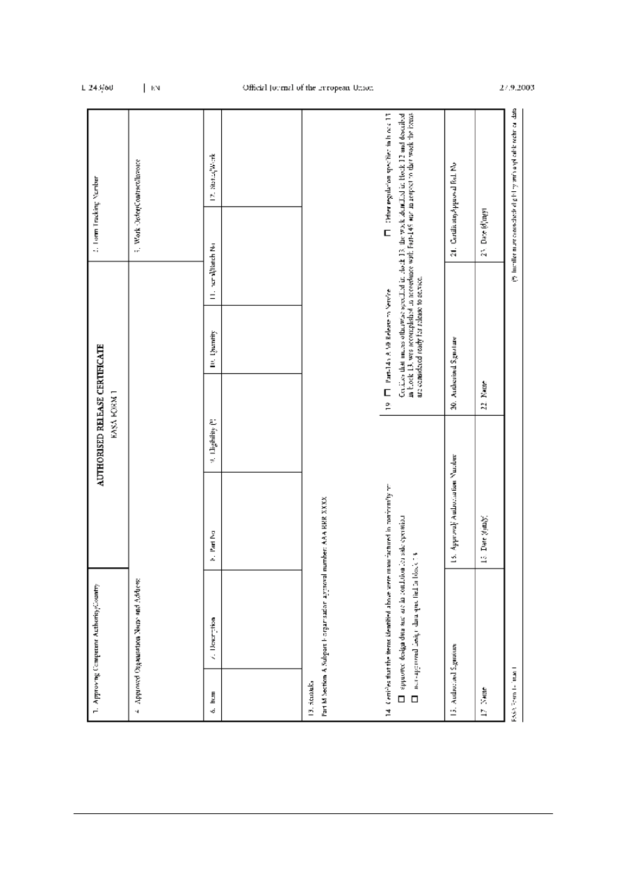
„Projekt współfinansowany ze środków Europejskiego Funduszu Społecznego”
59
Rys.17. EASA Form 1
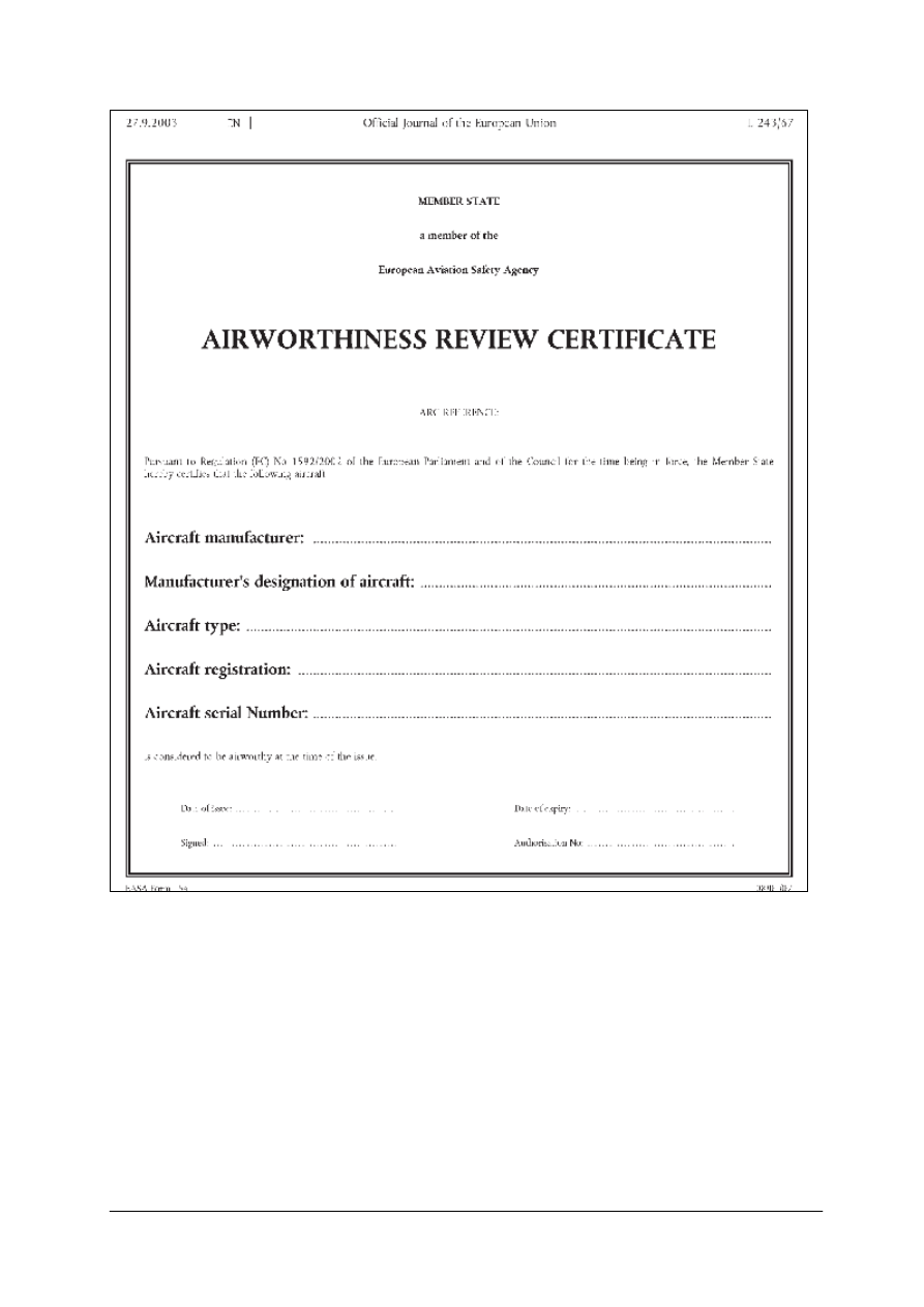
„Projekt współfinansowany ze środków Europejskiego Funduszu Społecznego”
60
Rys.18. EASA Form 15a
4.6.2. Pytania sprawdzające
Odpowiadając na pytania, sprawdzisz, czy jesteś przygotowany do wykonania ćwiczeń.
1. Jakim zwrotem określa się termin ”władza/organ zatwierdzający”?
2. Jakim zwrotem określa się termin ” zlecenie/umowa/faktura”?
3. Jakim zwrotem określa się termin ”poświadcza się, że elementy podane powyżej
zostały…”?
4. Jakim zwrotem określa się termin ”jest w stanie zapewniającym bezpieczne
użytkowanie”?
5. Jakim zwrotem określa się termin ”praca została wykonana zgodnie z”?
6. Jakim zwrotem określa się instrukcję, która jeśli nie jest przestrzegana może doprowadzić
do wypadku śmiertelnego?

„Projekt współfinansowany ze środków Europejskiego Funduszu Społecznego”
61
4.6.3. Ćwiczenia
Ćwiczenie 1
Znajdź tłumaczenie w słowniku języka angielskiego zwrotów umieszczonych w materiale
nauczania w rozdziale 4.6.1 Poradnika dla ucznia w lewej części tabeli 1. Porównaj uzyskane
tłumaczenie z prawą częścią tabeli.
Sposób wykonania ćwiczenia
Aby wykonać ćwiczenie, powinieneś:
1) sprawdzić w słowniku języka angielskiego znaczenie odpowiednich terminów,
2) zapisać tłumaczenie w notatniku.
Wyposażenie stanowiska pracy:
–
komputer z edytorem tekstu,
–
poradnik dla ucznia,
–
słownik języka angielskiego.
Ćwiczenie 2
Dokonaj tłumaczenia formularza nr 15a EASA zgodnie ze wzorem umieszczonym
w materiale nauczania w rozdziale 4.6.1 Poradnika dla ucznia.
Sposób wykonania ćwiczenia
Aby wykonać ćwiczenie, powinieneś:
1) przeanalizować formularz,
2) sprawdzić w słowniku języka angielskiego znaczenie odpowiednich terminów,
3) porównaj wynik swojej pracy z innymi uczniami.
Wyposażenie stanowiska pracy:
–
komputer z edytorem tekstu.
–
papier A4, przybory do pisania,
–
słownik języka angielskiego.
4.6.4. Sprawdzian postępów
Czy potrafisz:
Tak
Nie
1) przetłumaczyć znaczenie pól w formularzu 1 EASA?
2) przetłumaczyć znaczenie pól w formularzu 15a EASA?
3) podać dokładne znaczenie wyrażeń „WARNIG, CAUTION, NOTE”?

„Projekt współfinansowany ze środków Europejskiego Funduszu Społecznego”
62
5. SPRAWDZIAN OSIĄGNIĘĆ
INSTRUKCJA DLA UCZNIA
1. Przeczytaj uważnie instrukcję.
2. Podpisz imieniem i nazwiskiem kartę odpowiedzi.
3. Zapoznaj się z zestawem zadań testowych.
4. Test zawiera 20 zadań. Do każdego zadania dołączone są 4 możliwe odpowiedzi. Tylko
jedna jest prawidłowa.
5. Udzielaj odpowiedzi na załączonej karcie odpowiedzi, stawiając w odpowiedniej rubryce
znak „x”. W przypadku pomyłki należy błędną odpowiedź zaznaczyć kółkiem,
a następnie ponownie zakreślić odpowiedź prawidłową.
6. Pracuj samodzielnie, bo tylko wtedy będziesz miał satysfakcję z wykonanego zadania.
7. Jeśli udzielenie odpowiedzi będzie Ci sprawiało trudność, wtedy odłóż rozwiązanie
zadania na później i wróć do niego, gdy zostanie Ci wolny czas.
8. Na rozwiązanie testu masz 40 minut.
Powodzenia!
Materiały dla ucznia:
−
instrukcja,
−
zestaw zadań testowych,
−
karta odpowiedzi.
ZESTAW ZADAŃ TESTOWYCH
1. An aircraft with no crew on board in flight is called
a) UAV or RPV.
b) a crewless aerial vehicle.
c) no crew airplane.
d) unmanned rocket.
2. Aerostats fly makes
a) a very low weight.
b) a buoyant force.
c) Newton’s first law.
d) spinning propeller.
3. In a conventional wing configuration
a) the wing has the rectangular shape.
b) the wing is swept forward.
c) the wing is placed in front of the stabilizer.
d) the wing is placed above the fuselage.
4. The configuration with the stabilizer fore of the fuselage is called
a) reverse configuration.
b) low-wing configuration.
c) supersonic configuration.
d) canard configuration.

„Projekt współfinansowany ze środków Europejskiego Funduszu Społecznego”
63
5. The flying wing has
a) no fuselage.
b) has more than one fuselage.
c) has triangular shaped wings.
d) has wings placed one above the other.
6. The one wing airplane is called…
a) a sesquiplane.
b) a monoplane.
c) a monowing.
d) a tandem.
7. The tapered wing has got
a) a constant wing chord.
b) sharply swept leading and trailing edge.
c) the wing chord decreasing span-wise.
d) decreasing wing thickness.
8. The wing design with no external reinforcement is called
a) a wing spar.
b) a braced wing.
c) cantilever.
d) a clean wing configuration.
9. The seaplane has
a) the fuselage partially submerged in water.
b) skids in lieu of landing gear.
c) floats attached to the fuselage.
d) a tricycle landing gear.
10. The autogiro creates lift by
a) spinning powered rotor.
b) small wings attached to the fuselage.
c) a propeller providing a thrust.
d) utilizing an unpowered rotor.
11. Helicopters can fly forward by
a) using a propeller providing thrust.
b) using a tail rotor.
c) tilting the main rotor.
d) directing exhaust gas energy backward.
12. The engine thrust acts on an airplane
a) along airplane lateral axis.
b) along airplane longitudinal axis.
c) about airplane vertical axis.
d) about airplane lateral axis

„Projekt współfinansowany ze środków Europejskiego Funduszu Społecznego”
64
13. The main four forces acting on an aircraft are
a) thrust, drag, weight, lift.
b) gravity, push, drag, lift.
c) push, resistance, centrifugal, upper.
d) pull, wing, gravity, back.
14. A sharply swept leading edge with parallel trailing edge comprises:
a) a rectangular swept wing.
b) delta wing.
c) ogival wing.
d) mid-wing.
15. Helicopter may be powered by
a) turbojet engine.
b) ramjet engine.
c) turbofan engine.
d) turbine engine.
16. Thrust is
a) directly proportional to the weight and speed of fluid being displaced.
b) directly proportional to the speed and acceleration of fluid being displaced.
c) inversely proportional to the mass and velocity of fluid being displaced.
d) directly proportional to the mass and acceleration of fluid being displaced.
17. Ailerons change airplane position
a) about vertical axis.
b) about lateral axis.
c) about longitudinal axis
d) about normal axis.
18. The major wing structural members are
a) ribs, beams, longerons, skin.
b) beams, formers, bulkheads, skin.
c) spars, ribs, stringers, skin.
d) frames, bulkheads, formers, skin.
19. Aircraft carrying extra fuel for in-flight refueling is called a/an
a) tanker.
b) cargo aircraft.
c) airliner.
d) general aviation aircraft.
20. The strongest fuselage structural members are
a) ribs.
b) longerons.
c) formers.
d) bulkheads.

„Projekt współfinansowany ze środków Europejskiego Funduszu Społecznego”
65
KARTA ODPOWIEDZI
Imię i nazwisko:………………………………….
Posługiwanie się językiem angielskim zawodowym
Zakreśl poprawną odpowiedź.
Nr
zadania
Odpowiedź
Punkty
1.
a
b
c
d
2.
a
b
c
d
3.
a
b
c
d
4.
a
b
c
d
5.
a
b
c
d
6.
a
b
c
d
7.
a
b
c
d
8.
a
b
c
d
9.
a
b
c
d
10.
a
b
c
d
11.
a
b
c
d
12.
a
b
c
d
13.
a
b
c
d
14.
a
b
c
d
15.
a
b
c
d
16.
a
b
c
d
17.
a
b
c
d
18.
a
b
c
d
19.
a
b
c
d
20.
a
b
c
d
Razem:

„Projekt współfinansowany ze środków Europejskiego Funduszu Społecznego”
66
6. LITERATURA
1. Crane D.: Dictionary of Aeronautical Terms. Aviation Supplies & Academics Inc, 1997.
2. Mizgalski E.: Słownik techniczny polsko-angielski, angielsko-polski. Aneks. Wałbrzych
1994
3. Pawelec R, Oljasz T.: Poradnik jak pisać, wzory pism w języku angielskim. Wilga 2005.
4. U.S. Department of Transportation, Federal Aviation Administration, Flight Standards
Service.: Airframe and powerplant mechanics airframe handbook AC 65-15A. Summit
Aviation, Inc. 1992-2006.
5. http://www.globalsecurity.org/military/systems/aircraft/b767.htm
6. http://www.howstuffworks.com/
7. http://www.roymech.co.uk/Related/Pumps/Rotary%20Positive%20Displacement.html
8. http://www.tadano.co.jp/ihq/tadanocafe/index.html
9. http://en.wikipedia.org/wiki/Image:2006_Ojiya_balloon_festival_011.jpg Kropsoq.:NU 9.
10. http://en.wikipedia.org/wiki/Image:Heli.g-code.750pix.jpg Arpingstone.: Public domain 10.
11. http://en.wikipedia.org/wiki/Image:WestCoastAirFloatplane.jpg Leonard G.: Creative
commons 11.
12. http://en.wikipedia.org/wiki/Image:FA-22_Raptor.jpg USAF Public domain 12.
13. http://en.wikipedia.org/wiki/Image:PCB_design_and_realisation_smt_and_through_hole.
png Mike1024.: Public domain 13.
14. http://en.wikipedia.org/wiki/Image:KCL.png GNU 14.
15. http://en.wikipedia.org/wiki/Image:Capacitor.png Smack.: Public domain 15.
16. http://en.wikipedia.org/wiki/Image:Gratz.rectifier.en.png Public domain 16.
Wyszukiwarka
Podobne podstrony:
22 Posługiwanie się językiem angielskim zawodowym
08 Posługiwanie się językiem angielskim zawodowym
27 Posługiwanie się językiem obcym zawodowym
15 Posługiwanie się językiem obcym zawodowym
27 Posługiwanie się językiem obcym zawodowym
18 Posługiwanie się językiem obcym zawodowym
27 Posługiwanie się językiem obcym zawodowym
22 Posługiwanie się językiem obcym zawodowym
19 Posługiwanie się językiem obcym zawodowym
15 Posługiwanie się językiem obcym zawodowym 2
20 Posługiwanie się językiem obcym zawodowym
15 Posługiwanie się językiem obcym zawodowym
20 Poslugiwanie sie jezykiem ob Nieznany
27 Poslugiwanie sie jezykiem ob Nieznany (2)
03 Poslugiwanie sie dokumentacj Nieznany (2)
więcej podobnych podstron