Ćwiczenia wytrzymałość 7
Zadanie 25 (patrz program ZGIN zamieszczonej w książce na płycie CD oraz str.226-237)
Dla belki jednostronnie utwierdzonej obciążonej siłą skupioną P (rys.25), określić ugięcie w miejscu przyłożenia siły P. Moment bezwładności pola przekroju Jy = const. moduł Younga E = const. długość belki l, y - główna centralna oś pola przekroju belki.
z a - a z
a P
A B x y
a
l
Rys.25
Rozwiązanie
z T P w B'
Mx wB
A N 0 B w
x A B
x l - x x
Rys.25a
![]()
, ![]()
![]()
![]()
![]()
(a)
Warunki brzegowe:
x = 0, w' = 0 stąd C = 0; x = 0, w = 0 stąd D = 0
ostatecznie z (a)
![]()
dla x = l ![]()

(b)
Zadanie 26
Dla belki jednostronnie utwierdzonej obciążonej momentem gnącym M jak na rysunku 26, wyznaczyć ugięcie w miejscu przyłożenia momentu M. Moment bezwładności pola przekroju belki Jy = const., moduł Younga E = const. Długość belki wynosi l, y - główna centralna oś pola przekroju belki.
z M a-a z
a
A x y
a B
l
Rozwiązanie Rys.26
z T M w B'
Mx wB
A N B x A w B
x l - x Rys.26a x
![]()
, ![]()
,
![]()
![]()
,
![]()
(c)
Warunki brzegowe:
x = 0, w = 0 D = 0
x = 0, w' = 0 C = 0
ostatecznie z (c) ![]()
dla x = l 
(d)
Zadanie 27
Dla belki utwierdzonej jak na rysunku 27 obciążonej momentem M działającym zgodnie z rysunkiem 27, sporządzić wykresy sił wewnętrznych i momentu gnącego. Długość belki l, moment bezwładności pola przekroju belki Jy = const., moduł Younga E = const.,
y - centralna główna oś pola przekroju belki (rys.27).
y a - a z
a M
A B
x y
a
l Rys.27
Rozwiązanie
z RB
M
x
RB
w B'
wRB
x
w B'
wM
x Rys.27a
M
z (b) 
, z (d) 
dla x = l, 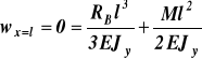
, ![]()
![]()
Siły wewnętrzne i moment gnący w przekroju x
y
Mx T RB
A N 0 B M
x
x l - x Rys.27b
Warunki równowagi odciętego elementu belki 0B (rys.27b)
1) ![]()
![]()
dla x = 0, ![]()
, dla x = l, ![]()
2) ![]()
N = 0
![]()
, ![]()
Wykresy sił wewnętrznych i momentu gnącego (rys.27c)
A N = 0 B
![]()
A B
M
A B Rys.27c
![]()
Zadanie 28 (patrz str 210-214 w/w książki)
Belka o przekroju poprzecznym w kształcie symetrycznego dwuteownika (rys.28), jest poddana działaniu siły tnącej T = 120 kN. Belka jest zbudowana z trzech płaskowników.
Płaskowniki są połączone ciągłą obustronną spoiną wzdłuż belki (rys.28a).
Określić wysokość spoiny a, uwzględniając tylko naprężenia od siły tnącej, jeżeli naprężenie dopuszczalne w spoinie τdop = 75 MPa.
z
T a
spoina
2H 2HSR 2h y
dS
dP Dane: dP = 5mm, dS = 5mm
H = 100mm, h = 95mm
b HSR = 97.5mm, b = 100mm
Rys.28
T = 120 kN
x
1 spoiny Rys.28a
Rozwiązanie
Naprężenia, które by zaistniały w przekroju z = h czyli w miejscu styku pasów ze środnikiem gdyby przekrój był jednolity

(e)
gdzie: Sy jest momentem statycznym pasa górnego względem osi głównej centralnej y
Jy jest momentem bezwładności całego pola przekroju względem osi y
![]()
![]()
![]()
![]()
(f)
Siła, która istniałaby w miejscu styku między pasem i półką przy długości styku równym jedności (rys.28b)
wynosi: z N x N/2
![]()
τ
τSP
y a
1 mm
dS Rys.28b
Siła ta wywołuje naprężenia w spoinach łączących pas ze środnikiem
![]()
![]()
![]()
(g)
ostatecznie
![]()
Zadanie 29 ( patrz program KRATA na płycie CD oraz str. 337-366 w/w książki)
Wyznaczyć wartości sił w prętach kratownicy, pokazanej na rysunku 29, przy zastosowaniu analitycznej metody równoważenia węzłów. Kratownica jest zbudowana z prętów o identycznej długości l = 3 m. Obciążenie kratownicy P1 = 50 kN, P2 = 40 kN.
C
P1 B trójkąty ABE, BCE, CDE są
5 trójkątami równobocznymi
3 4 6 7
P2
D
1 E 2 A Rys.29
Rozwiązanie
C
P1 B
y 5
3 4 6 7
RDy RE P2 h = lcos300 = 0.866l
RDx D
1 E 2 A x
l l Rys.29a
Obliczenie wartości reakcji
![]()
, ![]()
![]()
, ![]()
![]()
, ![]()
Obliczenie wartości sił w prętach y
Równania równowagi węzła A (rys.29b) N7
![]()
![]()
N2 A x
z rozwiązania tego układu równań otrzymujemy: P2 Rys.29b
N2 = -23.1 kN, N7 = 46.2 kN
Równania równowagi węzła B (rys.29c) y
![]()
N5 B x
![]()
niewiadomymi są wartości N5 i N6 N6 N7
N5 = 46.2 kN, N6 = - 46.2 kN Rys.29c
Równania równowagi węzła D (rys.29d) y
![]()
RDy N3
![]()
niewiadomymi są wartości N1 i N3 RDx D N1 x
N1 = 1.9 kN, N3 = 96.2 kN Rys.29d
Równania równowagi węzła E, w tym węźle nie jest znana tylko jedna siła N4, mamy do dyspozycji 2 równania po wyznaczeniu N4 z jednego równania drugie musi być spełnione
tożsamościowo
![]()
, N4 = - 96.2kN
![]()
, 0 = 0
2003-11-23 - 31 -
Wyszukiwarka
Podobne podstrony:
Planetarna przekładnia zębata, STUDIA MBM na PWR, IV Semestr, TMiM Gronowicz,Kazibudzki
Test zestaw 1(1), STUDIA MBM na PWR, III semestr, BHP iwko
Ergonomia pytania Otwarte(3), STUDIA MBM na PWR, III semestr, BHP iwko
laborka-cw5, STUDIA MBM na PWR, III semestr, Materiałoznawstwo Dudziński
MatLab ROZWIĄZANA lista na koło, Automatyka i robotyka air pwr, IV SEMESTR, MATLAB, Matlab zagadnien
analityczna egzamin pohl, Studia PWr, IV semestr, Chemia analityczna, Wykład (Pohl), Egzamin
pytanka na ustny, Automatyka i robotyka air pwr, IV SEMESTR, Podstawy automatyki 2, egzamin
elementy mroczka pytania mix by czaku, PWr, IV Semestr, Elementy Elektroniczne
ĆWICZENIE 9, Studia TOŚ, chemia analityczna-labor. semestr III
statystyka ściąga, Automatyka i robotyka air pwr, IV SEMESTR, statystyka stosowana
Automatyka SPRAWKO nandy, Automatyka i robotyka air pwr, IV SEMESTR, Podstawy automatyki 2, laborki
mroczka, PWr, IV Semestr, Elementy Elektroniczne
nandy, Automatyka i robotyka air pwr, IV SEMESTR, Podstawy automatyki 2, laborki
projekt przykł. 1 IMADŁO MASZYNOWE ŚRUBOWE - OBROTOWE, Studia, SiMR, II ROK, IV semestr, PKM, Materi
SPRAWKO ĆW1, Automatyka i robotyka air pwr, IV SEMESTR, Podstawy automatyki 2, laborki, CW.1
2x, Automatyka i robotyka air pwr, IV SEMESTR, MATLAB, Matlab zagadnienia
6-10 GD, Studia, SiMR, II ROK, IV semestr, IV semestr z dropa, Drgania mech, Opracowane pytania
więcej podobnych podstron