
EUROPEAN STANDARD
SU(1
NORME EUROPÉENNE
EUROPÄISCHE NORM
7 May 2003
UDC
Descriptors:
English version
Eurocode 3 : Design of steel structures
3DUW*HQHUDOUXOHVDQGUXOHVIRUEXLOGLQJV
Calcul des structures en acier
Bemessung und Konstruktion von Stahlbauten
Partie 1-1 : Règles générales et règles
Teil 1-1 : Allgemeine Bemessungsregeln und
pour les bâtiments
Regeln für den Hochbau
6WDJHGUDIW
&(1
European Committee for Standardisation
Comité Européen de Normalisation
Europäisches Komitee für Normung
&HQWUDO6HFUHWDULDWUXHGH6WDVVDUW%%UXVVHOV
© 2003 Copyright reserved to all CEN members
Ref. No. EN 1993-1-1 : 2003. E

3DJH
Final draft
SU(1
7 May 2003
&RQWHQW
3DJH
)RUHZRUG
*HQHUDO
1.1 Scope
9
1.1.1
Scope of Eurocode 3
9
1.1.2
Scope of Part 1.1 of Eurocode 3
10
1.2 Normative references
10
1.2.1
General reference standards
10
1.2.2
Weldable structural steel reference standards
10
1.3 Assumptions
11
1.4 Distinction between principles and application rules
11
1.5 Definitions
11
1.6 Symbols
12
1.7 Conventions for member axes
12
%DVLVRIGHVLJQ
2.1 Requirements
14
2.1.1
Basic requirements
14
2.1.2
Reliability management
14
2.1.3
Design working life, durability and robustness
14
2.2 Principles of limit state design
15
2.3 Basic variables
15
2.3.1
Actions and environmental influences
15
2.3.2
Material and product properties
15
2.4 Verification by the partial factor method
15
2.4.1
Design values of material properties
15
2.4.2
Design values of geometrical data
15
2.4.3
Design resistances
16
2.4.4
Verification of static equilibrium (EQU)
16
2.5 Design assisted by testing
16
0DWHULDOV
3.1 General
17
3.2 Structural steel
17
3.2.1
Material properties
17
3.2.2
Ductility requirements
17
3.2.3
Fracture toughness
17
3.2.4
Through-thickness properties
19
3.2.5
Tolerances
20
3.2.6
Design values of material coefficients
20
3.3 Connecting devices
20
3.3.1
Fasteners
20
3.3.2
Welding consumables
20
3.4 Other prefabricated products in buildings
20
'XUDELOLW\

Final draft
3DJH
7 May 2003
SU(1
6WUXFWXUDODQDO\VLV
5.1 Structural modelling for analysis
21
5.1.1
Structural modelling and basic assumptions
21
5.1.2
Joint modelling
21
5.1.3
Ground-structure interaction
21
5.2 Global analysis
22
5.2.1
Effects of deformed geometry of the structure
22
5.2.2
Structural stability of frames
23
5.3 Imperfections
24
5.3.1
Basis
24
5.3.2
Imperfections for global analysis of frames
25
5.3.3
Imperfection for analysis of bracing systems
28
5.3.4
Member imperfections
30
5.4 Methods of analysis considering material non-linearities
30
5.4.1
General
30
5.4.2
Elastic global analysis
31
5.4.3
Plastic global analysis
31
5.5 Classification of cross sections
32
5.5.1
Basis
32
5.5.2
Classification
32
5.6 Cross-section requirements for plastic global analysis
33
8OWLPDWHOLPLWVWDWHV
6.1 General
37
6.2 Resistance of cross-sections
37
6.2.1
General
37
6.2.2
Section properties
38
6.2.3
Tension
41
6.2.4
Compression
41
6.2.5
Bending moment
42
6.2.6
Shear
42
6.2.7
Torsion
44
6.2.8
Bending and shear
45
6.2.9
Bending and axial force
46
6.2.10
Bending, shear and axial force
48
6.3 Buckling resistance of members
48
6.3.1
Uniform members in compression
48
6.3.2
Uniform members in bending
52
6.3.3
Uniform members in bending and axial compression
56
6.3.4
General method for lateral and lateral torsional buckling of structural components
57
6.3.5
Lateral torsional buckling of members with plastic hinges
59
6.4 Uniform built-up compression members
61
6.4.1
General
61
6.4.2
Laced compression members
63
6.4.3
Battened compression members
64
6.4.4
Closely spaced built-up members
66
6HUYLFHDELOLW\OLPLWVWDWHV
7.1 General
67
7.2 Serviceability limit states for buildings
67
7.2.1
Vertical deflections
67
7.2.2
Horizontal deflections
67
7.2.3
Dynamic effects
67

3DJH
Final draft
SU(1
7 May 2003
$QQH[$>LQIRUPDWLYH@±0HWKRG,QWHUDFWLRQIDFWRUVN
LM
IRULQWHUDFWLRQIRUPXODLQ
$QQH[%>LQIRUPDWLYH@±0HWKRG,QWHUDFWLRQIDFWRUVN
LM
IRULQWHUDFWLRQIRUPXODLQ
$QQH[$%>LQIRUPDWLYH@±$GGLWLRQDOGHVLJQSURYLVLRQV
AB.1 Structural analysis taking account of material non-linearities
72
AB.2 Simplified provisions for the design of continuous floor beams
72
$QQH[%%>LQIRUPDWLYH@±%XFNOLQJRIFRPSRQHQWVRIEXLOGLQJVWUXFWXUHV
BB.1
Flexural buckling of members in triangulated and lattice structures
73
BB.1.1
General
73
BB.1.2
Angles as web members
73
BB.1.3
Hollow sections as members
73
BB.2
Continuous restraints
74
BB.2.1
Continuous lateral restraints
74
BB.2.2
Continuous torsional restraints
74
BB.3
Stable lengths of segment containing plastic hinges for out-of-plane buckling
75
BB.3.1
Uniform members made of rolled sections or equivalent welded I-sections
75
BB.3.2
Haunched or tapered members made of rolled sections or equivalent welded I-sections
79
BB.3.3
Modification factors for moment gradients in members laterally restrained along the
tension flange
80

Final draft
3DJH
7 May 2003
SU(1
)RUHZRUG
This European Standard EN 1993-1-1, Design of Steel Structures : General rules and rules for buildings, has
been prepared on behalf of Technical Committee CEN/TC250 « Structural Eurocodes », the Secretariat of
which is held by BSI. CEN/TC250 is responsible for all Structural Eurocodes.
The text of the draft standard was submitted to the formal vote and was approved by CEN as EN 1993-1-1
on YYYY-MM-DD.
No existing European Standard is superseded.
%DFNJURXQGRIWKH(XURFRGHSURJUDPPH
In 1975, the Commission of the European Community decided on an action programme in the field of
construction, based on article 95 of the Treaty. The objective of the programme was the elimination of
technical obstacles to trade and the harmonisation of technical specifications.
Within this action programme, the Commission took the initiative to establish a set of harmonised technical
rules for the design of construction works which, in a first stage, would serve as an alternative to the national
rules in force in the Member States and, ultimately, would replace them.
For fifteen years, the Commission, with the help of a Steering Committee with Representatives of Member
States, conducted the development of the Eurocodes programme, which led to the first generation of
European codes in the 1980s.
In 1989, the Commission and the Member States of the EU and EFTA decided, on the basis of an agreement
1
between the Commission and CEN, to transfer the preparation and the publication of the Eurocodes to the
CEN through a series of Mandates, in order to provide them with a future status of European Standard (EN).
This links
GHIDFWR the Eurocodes with the provisions of all the Council’s Directives and/or Commission’s
Decisions dealing with European standards (e.g. the Council Directive 89/106/EEC on construction products
– CPD – and Council Directives 93/37/EEC, 92/50/EEC and 89/440/EEC on public works and services and
equivalent EFTA Directives initiated in pursuit of setting up the internal market).
The Structural Eurocode programme comprises the following standards generally consisting of a number of
Parts:
EN 1990
Eurocode:
Basis of structural design
EN 1991
Eurocode 1:
Actions on structures
EN 1992
Eurocode 2:
Design of concrete structures
EN 1993
Eurocode 3:
Design of steel structures
EN 1994
Eurocode 4:
Design of composite steel and concrete structures
EN 1995
Eurocode 5:
Design of timber structures
EN 1996
Eurocode 6:
Design of masonry structures
EN 1997
Eurocode 7:
Geotechnical design
EN 1998
Eurocode 8:
Design of structures for earthquake resistance
EN 1999
Eurocode 9:
Design of aluminium structures
Eurocode standards recognise the responsibility of regulatory authorities in each Member State and have
safeguarded their right to determine values related to regulatory safety matters at national level where these
continue to vary from State to State.
1
Agreement between the Commission of the European Communities and the European Committee for Standardisation (CEN)
concerning the work on EUROCODES for the design of building and civil engineering works (BC/CEN/03/89).

3DJH
Final draft
SU(1
7 May 2003
6WDWXVDQGILHOGRIDSSOLFDWLRQRI(XURFRGHV
The Member States of the EU and EFTA recognise that Eurocodes serve as reference documents for the
following purposes :
–
as a means to prove compliance of building and civil engineering works with the essential requirements
of Council Directive 89/106/EEC, particularly Essential Requirement N°1 - Mechanical resistance and
stability - and Essential Requirement N°2 - Safety in case of fire;
–
as a basis for specifying contracts for construction works and related engineering services;
–
as a framework for drawing up harmonised technical specifications for construction products (ENs and
ETAs)
The Eurocodes, as far as they concern the construction works themselves, have a direct relationship with the
Interpretative Documents
2
referred to in Article 12 of the CPD, although they are of a different nature from
harmonised product standard
3
. Therefore, technical aspects arising from the Eurocodes work need to be
adequately considered by CEN Technical Committees and/or EOTA Working Groups working on product
standards with a view to achieving a full compatibility of these technical specifications with the Eurocodes.
The Eurocode standards provide common structural design rules for everyday use for the design of whole
structures and component products of both a traditional and an innovative nature. Unusual forms of
construction or design conditions are not specifically covered and additional expert consideration will be
required by the designer in such cases.
1DWLRQDO6WDQGDUGVLPSOHPHQWLQJ(XURFRGHV
The National Standards implementing Eurocodes will comprise the full text of the Eurocode (including any
annexes), as published by CEN, which may be preceded by a National title page and National foreword, and
may be followed by a National annex (informative).
The National Annex (informative) may only contain information on those parameters which are left open in
the Eurocode for national choice, known as Nationally Determined Parameters, to be used for the design of
buildings and civil engineering works to be constructed in the country concerned, i.e. :
–
values for partial factors and/or classes where alternatives are given in the Eurocode,
–
values to be used where a symbol only is given in the Eurocode,
–
geographical and climatic data specific to the Member State, e.g. snow map,
–
the procedure to be used where alternative procedures are given in the Eurocode,
–
references to non-contradictory complementary information to assist the user to apply the Eurocode.
/LQNVEHWZHHQ(XURFRGHVDQGSURGXFWKDUPRQLVHGWHFKQLFDOVSHFLILFDWLRQV(1V
DQG(7$V
There is a need for consistency between the harmonised technical specifications for construction products
and the technical rules for works
4
. Furthermore, all the information accompanying the CE Marking of the
construction products which refer to Eurocodes should clearly mention which Nationally Determined
Parameters have been taken into account.
2
According to Art. 3.3 of the CPD, the essential requirements (ERs) shall be given concrete form in interpretative documents for the
creation of the necessary links between the essential requirements and the mandates for hENs and ETAGs/ETAs.
3
According to Art. 12 of the CPD the interpretative documents shall :
a) give concrete form to the essential requirements by harmonising the terminology and the technical bases and indicating classes
or levels for each requirement where necessary ;
b) indicate methods of correlating these classes or levels of requirement with the technical specifications, e.g. methods of
calculation and of proof, technical rules for project design, etc. ;
c) serve as a reference for the establishment of harmonised standards and guidelines for European technical approvals.
The Eurocodes,
GHIDFWR, play a similar role in the field of the ER 1 and a part of ER 2.
4
See Art.3.3 and Art.12 of the CPD, as well as clauses 4.2, 4.3.1, 4.3.2 and 5.2 of ID 1.

Final draft
3DJH
7 May 2003
SU(1
$GGLWLRQDOLQIRUPDWLRQVSHFLILFWR(1
EN 1993 is intended to be used with Eurocodes EN 1990 – Basis of Structural Design, EN 1991 – Actions on
structures and EN 1992 to EN 1999, when steel structures or steel components are referred to.
EN 1993-1 is the first of six parts of EN 1993 – Design of Steel Structures. It gives generic design rules
intended to be used with the other parts EN 1993-2 to EN 1993-6. It also gives supplementary rules
applicable only to buildings.
EN 1993-1 comprises eleven subparts EN 1993-1-1 to EN 1993-1-11 each addressing specific steel
components, limit states or materials.
It may also be used for design cases not covered by the Eurocodes (other structures, other actions, other
materials) serving as a reference document for other CEN TC´s concerning structural matters.
EN 1993-1 is intended for use by
–
committees drafting design related product, testing and execution standards,
–
clients (e.g. for the formulation of their specific requirements)
–
designers and constructors
–
relevant authorities
Numerical values for partial factors and other reliability parameters are recommended as basic values that
provide an acceptable level of reliability. They have been selected assuming that an appropriate level of
workmanship and quality management applies.

3DJH
Final draft
SU(1
7 May 2003
1DWLRQDODQQH[IRU(1
This standard gives alternative procedures, values and recommendations for classes with notes indicating
where national choices may be made. Therefore the National Standard implementing EN 1993-1 should have
a National Annex containing all Nationally Determined Parameters to be used for the design of steel
structures to be constructed in the relevant country.
National choice is allowed in EN 1993-1-1 through paragraphs:
–
2.3.1(1)
–
3.1(2)
–
3.2.1(1)
–
3.2.2(1)
–
3.2.3(1)
–
3.2.3(3)B
–
3.2.4(1)B
–
5.2.1(3)
–
5.2.2(8)
–
5.3.2(3)
–
5.3.2(11)
–
5.3.4(3)
–
6.1(1)B
–
6.1(1)
–
6.3.2.2(2)
–
6.3.2.3(1)
–
6.3.2.3(2)
–
6.3.2.4(1)B
–
6.3.2.4(2)B
–
6.3.3(5)
–
6.3.4(1)
–
7.2.1(1)B
–
7.2.2(1)B
–
7.2.3(1)B
–
BB.1.3(3)B

Final draft
3DJH
7 May 2003
SU(1
*HQHUDO
6FRSH
6FRSHRI(XURFRGH
(1)
Eurocode 3 applies to the design of buildings and civil engineering works in steel. It complies with the
principles and requirements for the safety and serviceability of structures, the basis of their design and
verification that are given in EN 1990 – Basis of structural design.
(2)
Eurocode 3 is concerned only with requirements for resistance, serviceability, durability and fire
resistance of steel structures. Other requirements, e.g. concerning thermal or sound insulation, are not
covered.
(3)
Eurocode 3 is intended to be used in conjunction with:
–
EN 1990 “Basis of structural design”
–
EN 1991 “Actions on structures”
–
ENs, ETAGs and ETAs for construction products relevant for steel structures
–
EN 1090 “Execution of steel structures – Technical requirements”
–
EN 1992 to EN 1999 when steel structures or steel components are referred to
(4)
Eurocode 3 is subdivided in various parts:
EN 1993-1 Design of Steel Structures : General rules and rules for buildings.
EN 1993-2 Design of Steel Structures : Steel bridges.
EN 1993-3 Design of Steel Structures : Towers, masts and chimneys.
EN 1993-4 Design of Steel Structures : Silos, tanks and pipelines.
EN 1993-5 Design of Steel Structures : Piling.
EN 1993-6 Design of Steel Structures : Crane supporting structures.
(5)
EN 1993-2 to EN 1993-6 refer to the generic rules in EN 1993-1. The rules in parts EN 1993-2 to
EN 1993-6 supplement the generic rules in EN 1993-1.
(6)
EN 1993-1 “General rules and rules for buildings” comprises:
EN 1993-1-1
Design of Steel Structures : General rules and rules for buildings.
EN 1993-1-2
Design of Steel Structures : Structural fire design.
EN 1993-1-3
Design of Steel Structures : Cold-formed thin gauge members and sheeting.
EN 1993-1-4
Design of Steel Structures : Stainless steels.
EN 1993-1-5
Design of Steel Structures : Plated structural elements.
EN 1993-1-6
Design of Steel Structures : Strength and stability of shell structures.
EN 1993-1-7
Design of Steel Structures : Strength and stability of planar plated structures transversely
loaded.
EN 1993-1-8
Design of Steel Structures : Design of joints.
EN 1993-1-9
Design of Steel Structures : Fatigue strength of steel structures.
EN 1993-1-10 Design of Steel Structures : Selection of steel for fracture toughness and through-thickness
properties.
EN 1993-1-11 Design of Steel Structures : Design of structures with tension components made of steel.

3DJH
Final draft
SU(1
7 May 2003
6FRSHRI3DUWRI(XURFRGH
(1)
EN 1993-1-1 gives basic design rules for steel structures with material thicknesses t
≥ 3 mm. It also
gives supplementary provisions for the structural design of steel buildings. These supplementary provisions
are indicated by the letter “B” after the paragraph number, thus ( )B.
127( For cold formed thin gauge members and plate thicknesses t < 3 mm see EN 1993-1-3.
(2)
The following subjects are dealt with in EN 1993-1-1:
Section 1: General
Section 2: Basis of design
Section 3: Materials
Section 4: Durability
Section 5: Structural analysis
Section 6: Ultimate limit states
Section 7: Serviceability limit states
(3)
Sections 1 to 2 provide additional clauses to those given in EN 1990 “Basis of structural design”.
(4)
Section 3 deals with material properties of products made of low alloy structural steels.
(5)
Section 4 gives general rules for durability.
(6)
Section 5 refers to the structural analysis of structures, in which the members can be modelled with
sufficient accuracy as line elements for global analysis.
(7)
Section 6 gives detailed rules for the design of cross sections and members.
(8)
Section 7 gives rules for serviceability.
1RUPDWLYHUHIHUHQFHV
The following normative documents contain provisions which, through reference in this text, constitute
provisions of this European Standard. For dated references, subsequent amendments to or revisions of any of
these publications do not apply. However, parties to agreements based on this European Standard are
encouraged to investigate the possibility of applying the most recent editions of the normative documents
indicated below. For undated references the latest edition of the normative document referred to applies.
*HQHUDOUHIHUHQFHVWDQGDUGV
EN 1090
Execution of steel structures – Technical requirements
EN ISO 12944
Paints and varnishes – Corrosion protection of steel structures by protective paint systems
EN 1461
Hot dip galvanised coatings on fabricated iron and steel articles – specifications and test
methods
:HOGDEOHVWUXFWXUDOVWHHOUHIHUHQFHVWDQGDUGV
EN 10025-1: January 2002
Hot-rolled products of structural steels - Part 1: General delivery conditions.
EN 10025-2: January 2002
Hot-rolled products of structural steels - Part 2: Technical delivery conditions
for non-alloy structural steels.
EN 10025-3: January 2002
Hot-rolled products of structural steels - Part 3: Technical delivery conditions
for normalized / normalized rolled weldable fine grain structural steels.

Final draft
3DJH
7 May 2003
SU(1
EN 10025-4: March 2002
Hot-rolled products of structural steels - Part 4: Technical delivery conditions
for thermomechanical rolled weldable fine grain structural steels.
EN 10025-5: March 2002
Hot-rolled products of structural steels - Part 5: Technical delivery conditions
for structural steels with improved atmospheric corrosion resistance.
EN 10025-6: March 2002
Hot-rolled products of structural steels - Part 6: Technical delivery conditions
for flat products of high yield strength structural steels in the quenched and
tempered condition.
EN 10164: 1993
Steel products with improved deformation properties perpendicular to the
surface of the product - Technical delivery conditions.
EN 10210-1: February 2002
Hot finished structural hollow sections of non-alloy and fine grain structural
steels – Part 1: Technical delivery requirements.
EN 10219-1: February 2002
Cold formed hollow sections of structural steel - Part 1: Technical delivery
requirements.
$VVXPSWLRQV
(1)
In addition to the general assumptions of EN 1990 the following assumptions apply:
–
fabrication and erection complies with EN 1090
'LVWLQFWLRQEHWZHHQSULQFLSOHVDQGDSSOLFDWLRQUXOHV
(1)
The rules in EN 1990 clause 1.4 apply.
'HILQLWLRQV
(1)
The rules in EN 1990 clause 1.5 apply.
(2)
The following terms are used in EN 1993-1-1 with the following meanings:
IUDPH
the whole or a portion of a structure, comprising an assembly of directly connected structural elements,
designed to act together to resist load; this term refers to both moment-resisting frames and triangulated
frames; it covers both plane frames and three-dimensional frames
VXEIUDPH
a frame that forms part of a larger frame, but is be treated as an isolated frame in a structural analysis
W\SHRIIUDPLQJ
terms used to distinguish between frames that are either:
–
VHPLFRQWLQXRXV, in which the structural properties of the members and joints need explicit
consideration in the global analysis
–
FRQWLQXRXV, in which only the structural properties of the members need be considered in the global
analysis
–
VLPSOH, in which the joints are not required to resist moments
JOREDODQDO\VLV
the determination of a consistent set of internal forces and moments in a structure, which are in equilibrium
with a particular set of actions on the structure

3DJH
Final draft
SU(1
7 May 2003
V\VWHPOHQJWK
distance in a given plane between two adjacent points at which a member is braced against lateral
displacement in this plane, or between one such point and the end of the member
EXFNOLQJOHQJWK
system length of an otherwise similar member with pinned ends, which has the same buckling resistance as a
given member or segment of member
VKHDUODJHIIHFW
non-uniform stress distribution in wide flanges due to shear deformation; it is taken into account by using a
reduced “effective” flange width in safety assessments
FDSDFLW\GHVLJQ
design method for achieving the plastic deformation capacity of a member by providing additional strength
in its connections and in other parts connected to it
XQLIRUPPHPEHU
member with a constant cross-section along its whole length
6\PEROV
(1)
For the purpose of this standard the following symbols apply.
'UDIWQRWH Will be added later.
&RQYHQWLRQVIRUPHPEHUD[HV
(1)
The convention for member axes is:
x-x
- along the member
y-y
- axis of the cross-section
z-z
- axis of the cross-section
(2)
For steel members, the conventions used for cross-section axes are:
–
generally:
y-y
- cross-section axis parallel to the flanges
z-z
- cross-section axis perpendicular to the flanges
–
for angle sections:
y-y
- axis parallel to the smaller leg
z-z
- axis perpendicular to the smaller leg
–
where necessary:
u-u
- major principal axis (where this does not coincide with the yy axis)
v-v
- minor principal axis (where this does not coincide with the zz axis)
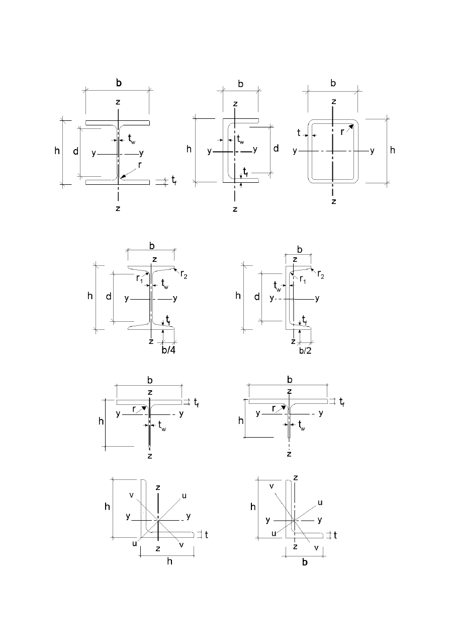
(3)
The symbols used for dimensions and axes of rolled steel sections are indicated in Figure 1.1.
(4)
The convention used for subscripts that indicate axes for moments is: "Use the axis about which the
moment acts."
Final draft
3DJH
7 May 2003
SU(1
127( All rules in this Eurocode relate to principal axis properties, which are generally defined by
the axes y-y and z-z but for sections such as angles are defined by the axes u-u and v-v.
)LJXUH'LPHQVLRQVDQGD[HVRIVHFWLRQV

3DJH
Final draft
SU(1
7 May 2003
%DVLVRIGHVLJQ
5HTXLUHPHQWV
%DVLFUHTXLUHPHQWV
(1)
The design of steel structures shall be in accordance with the general rules given in EN 1990.
(2)
The supplementary provisions for steel structures given in this section shall also be applied.
(3)
The basic requirements of EN 1990 section 2 shall be deemed be satisfied where limit state design is
used in conjunction with the partial factor method and the load combinations given in EN 1990 together with
the actions given in EN 1991.
(4)
The rules for resistances, serviceability and durability given in the various parts of EN 1993 should be
applied.
5HOLDELOLW\PDQDJHPHQW
(1)
Where different levels of reliability are required, these levels should preferably be achieved by an
appropriate choice of quality management in design and execution, according to EN 1990 Annex C and
EN 1090.
'HVLJQZRUNLQJOLIHGXUDELOLW\DQGUREXVWQHVV
*HQHUDO
(1)
Depending upon the type of action affecting durability and the design working life (see EN 1990) steel
structures should be
–
designed against corrosion by means of
–
suitable surface protection (see EN ISO 12944)
–
the use of weathering steel
–
the use of stainless steel (see EN 1993-1-4)
–
detailed for sufficient fatigue life (see EN 1993-1-9)
–
designed for wearing
–
designed for accidental actions (see EN 1991-1-7)
–
inspected and maintained.
'HVLJQZRUNLQJOLIHIRUEXLOGLQJV
(1)B The design working life should be taken as the period for which a building structure is expected to be
used for its intended purpose.
(2)B For the specification of the intended design working life of a permanent building see Table 2.1 of
EN 1990.
(3)B For structural elements that cannot be designed for the total design life of the building, see
2.1.3.3(3)B.
'XUDELOLW\IRUEXLOGLQJV
(1)B To ensure durability, buildings and their components should either be designed for environmental
actions and fatigue if relevant or else protected from them.

Final draft
3DJH
7 May 2003
SU(1
(2)B The effects of deterioration of material, corrosion or fatigue where relevant should be taken into
account by appropriate choice of material, see EN 1993-1-4 and EN 1993-1-10, and details, see
EN 1993-1-9, or by structural redundancy and by the choice of an appropriate corrosion protection system.
(3)B If a building includes components that need to be replaceable (e.g. bearings in zones of soil
settlement), the possibility of their safe replacement should be verified as a transient design situation.
3ULQFLSOHVRIOLPLWVWDWHGHVLJQ
(1)
The resistances of cross-sections and members specified in this Eurocode 3 for the ultimate limit states
as defined in EN 1990-3.3 are based on tests in which the material exhibited sufficient ductility to apply
simplified design models.
(2)
The resistances specified in this Eurocode Part may therefore be used where the conditions for
materials in section 3 are met.
%DVLFYDULDEOHV
$FWLRQVDQGHQYLURQPHQWDOLQIOXHQFHV
(1)
Actions for the design of steel structures should be taken from EN 1991. For the combination of
actions and partial factors of actions see Annex A to EN 1990
127( The National Annex may define actions for particular regional or climatic or accidental
situations.
127(% For proportional loading for incremental approach, see Annex AB.1.
127(% For simplified load arrangement, see Annex AB.2.
(2)
The actions to be considered in the erection stage should be obtained from EN 1991-1-6.
(3)
Where the effects of predicted absolute and differential settlements need to be considered, best
estimates of imposed deformations should be used.
(4)
The effects of uneven settlements or imposed deformations or other forms of prestressing imposed
during erection should be taken into account by their nominal value P
k
as permanent actions and grouped
with other permanent actions G
k
from a single action (G
k
+ P
k
).
(5)
Fatigue actions not defined in EN 1991 should be determined according to Annex A of EN 1993-1-9.
0DWHULDODQGSURGXFWSURSHUWLHV
(1)
Material properties for steels and other construction products and the geometrical data to be used for
design should be those specified in the relevant ENs, ETAGs or ETAs unless otherwise indicated in this
standard.
9HULILFDWLRQE\WKHSDUWLDOIDFWRUPHWKRG
'HVLJQYDOXHVRIPDWHULDOSURSHUWLHV
(1)
For the design of steel structures characteristic values X
K
or nominal values X
n
of material properties
shall be used as indicated in this Eurocode.
'HVLJQYDOXHVRIJHRPHWULFDOGDWD
(1)
Geometrical data for cross-sections and systems may be taken from product standards hEN or
drawings for the execution to EN 1090 and treated as nominal values.
3DJH
Final draft
SU(1
7 May 2003
(2)
Design values of geometrical imperfections specified in this standard are equivalent geometric
imperfections that take into account the effects of:
–
geometrical imperfections of members as governed by geometrical tolerances in product standards or the
execution standard,
–
structural imperfections due to fabrication and erection,
–
residual stresses,
–
variation of the yield strength.
'HVLJQUHVLVWDQFHV
(1)
For steel structures equation (6.6c) or equation (6.6d) of EN 1990 applies:
(
)
d
ki
i
1
k
1
k
M
M
k
d
a
;
X
;
X
R
1
R
R
η
η
γ
=
γ
=
(2.1)
where R
k
is the characteristic value of the particular resistance determined with characteristic or nominal
values for the material properties and dimensions
γ
M
is the global partial factor for the particular resistance
127( For the definitions of η
1
,
η
i
, X
k1
, X
ki
and a
d
see EN 1990.
9HULILFDWLRQRIVWDWLFHTXLOLEULXP(48
(1)
The reliability format for the verification of static equilibrium in Table 1.2 (A) in Annex A of EN
1990 also applies to design situations equivalent to (EQU), e.g. for the design of holding down anchors or the
verification of uplift of bearings of continuous beams.
'HVLJQDVVLVWHGE\WHVWLQJ
(1)
The resistances R
k
in this standard have been determined using Annex D of EN 1990.
(2)
In recommending classes of constant partial
IDFWRUV
Mi
the characteristic values R
k
were obtained from
R
k
= R
d
Mi
(2.2)
where R
d
are design values according to Annex D of EN 1990
γ
Mi
are recommended partial factors.
127(7KHQXPHULFDOYDOXHVRIWKHUHFRPPHQGHGSDUWLDOIDFWRUV
Mi
have been determined such that
R
k
represents approximately the 5 %-fractile for an infinite number of tests.
127( )RU FKDUDFWHULVWLF YDOXHV RI IDWLJXH VWUHQJWK DQG SDUWLDO IDFWRUV
Mf
for fatigue see
EN 1993-1-9.
127( For characteristic values of toughness resistance and safety elements for the toughness
verification see EN 1993-1-10.
(3)
Where resistances R
k
for prefabricated products shall be determined from tests, the procedure in (2)
should be followed.

Final draft
3DJH
7 May 2003
SU(1
0DWHULDOV
*HQHUDO
(1)
The nominal values of material properties given in this section should be adopted as characteristic
values in design calculations.
(2)
This Part of EN 1993 covers the design of steel structures fabricated from steel material conforming to
the steel grades listed in Table 3.1.
127( For other steel material and products see National Annex.
6WUXFWXUDOVWHHO
0DWHULDOSURSHUWLHV
(1)
The nominal values of the yield strength f
y
and the ultimate strength f
u
for structural steel shall be
obtained
a) either by adopting the values f
y
= R
eh
and f
u
= R
m
direct from the product standard
b) or by using the simplification given in Table 3.1
127( The National Annex may give the choice.
'XFWLOLW\UHTXLUHPHQWV
(1)
For steels a minimum ductility is required that should be expressed in terms of limits for:
–
the ratio f
u
/ f
y
of the specified minimum ultimate tensile strength f
u
to the specified minimum yield
strength f
y
;
–
the elongation at failure on a gauge length of 5,65
o
A
(where A
0
is the original cross-sectional area);
–
the ultimate strain
ε
u
, where
ε
u
corresponds to the ultimate strength f
u
.
127( The limiting values of the ratio f
u
/ f
y
, the elongation at failure and the ultimate strain
ε
u
may
be defined in the National Annex. The following values are recommended:
–
f
u
/ f
y
≥ 1,10;
–
elongation at failure not less than 15%;
–
ε
u
≥ 15ε
y
, where
ε
y
is the yield strain (
ε
y
= f
y
/ E).
(2)
Steel conforming with one of the steel grades listed in Table 3.1 should be accepted as satisfying these
requirements.
)UDFWXUHWRXJKQHVV
(1)
The material shall have sufficient fracture toughness to avoid brittle fracture of tension elements at the
lowest service temperature expected to occur within the intended design life of the structure.
127( The lowest service temperature to be adopted in design may be given in the National Annex.
(2)
No further check against brittle fracture need to be made if the conditions given in EN 1993-1-10 are
satisfied for the lowest temperature.

3DJH
Final draft
SU(1
7 May 2003
(3)B For building components under compression a suitable minimum toughness property should be
selected.
127( % The National Annex may give information on the selection of toughness properties for
members in compression. The use of Table 2.1 of EN 1993-1-10 for
σ
Ed
= 0,25 f
y
(t) is recommended.
(4)
For selecting steels for members with hot dip galvanized coatings see EN 1064.
7DEOH1RPLQDOYDOXHVRI\LHOGVWUHQJWKI
\
DQGXOWLPDWHWHQVLOHVWUHQJWKI
X
IRU
KRWUROOHGVWUXFWXUDOVWHHO
Nominal thickness of the element t [mm]
t
PP
40 mm < t
PP
Standard
and
steel grade
f
y
[N/mm
2
]
f
u
[N/mm
2
]
f
y
[N/mm
2
]
f
u
[N/mm
2
]
(1
S 235
235
360
215
360
S 275
275
430
255
410
S 355
355
510
335
470
S 450
440
550
410
550
(1
S 275 N/NL
275
390
255
370
S 355 N/NL
355
490
335
470
S 420 N/NL
420
520
390
520
S 460 N/NL
460
540
430
540
(1
S 275 M/ML
275
370
255
360
S 355 M/ML
355
470
335
450
S 420 M/ML
420
520
390
500
S 460 M/ML
460
540
430
530
(1
S 235 W
235
360
215
340
S 355 W
355
510
335
490
(1
S 460 Q/QL/QL1
460
570
440
550
Final draft
3DJH
7 May 2003
SU(1
7DEOHFRQWLQXHG1RPLQDOYDOXHVRI\LHOGVWUHQJWKI
\
DQGXOWLPDWHWHQVLOH
VWUHQJWKI
X
IRUVWUXFWXUDOKROORZVHFWLRQV
Nominal thickness of the element t [mm]
t
PP
40 mm < t
PP
Standard
and
steel grade
f
y
[N/mm
2
]
f
u
[N/mm
2
]
f
y
[N/mm
2
]
f
u
[N/mm
2
]
(1
S 235 H
235
360
215
340
S 275 H
275
430
255
410
S 355 H
355
510
335
490
S 275 NH/NLH
275
390
255
370
S 355 NH/NLH
355
490
335
470
S 420 NH/NHL
420
540
390
520
S 460 NH/NLH
460
560
430
550
(1
S 235 H
235
360
S 275 H
275
430
S 355 H
355
510
S 275 NH/NLH
275
370
S 355 NH/NLH
355
470
S 460 NH/NLH
460
550
S 275 MH/MLH
275
360
S 355 MH/MLH
355
470
S 420 MH/MLH
420
500
S 460 MH/MLH
460
530
7KURXJKWKLFNQHVVSURSHUWLHV
(1)
Where steel with improved through-thickness properties is necessary according to EN 1993-1-10, steel
according to the required quality class in EN 10164 should be used.
127( Guidance on the choice of through-thickness properties is given in EN 1993-1-10.
127(% Particular care should be given to welded beam to column connections and welded end
plates with tension in the through-thickness direction.
127(% The National Annex may give the relevant allocation of target values Z
Ed
according to
3.2(3) of EN 1993-1-10 to the quality class in EN 10164. The allocation in Table 3.2 is recommended
for buildings:
7DEOH&KRLFHRITXDOLW\FODVVDFFRUGLQJWR(1
Target value of
Z
Ed
according to
EN 1993-1-10
Required value of
Z
Rd
according to
EN 10164
Z
Ed
—
10 < Z
Ed
Z 15
20 < Z
Ed
Z 25
Z
Ed
> 30
Z 35

3DJH
Final draft
SU(1
7 May 2003
7ROHUDQFHV
(1)
The dimensional and mass tolerances of rolled steel sections, structural hollow sections and plates
should conform with the relevant product standard, ETAG or ETA unless more severe tolerances are
specified.
(2)
For welded components the tolerances given in EN 1090 should be applied.
(3)
For structural analysis and design the nominal values of dimensions should be used.
'HVLJQYDOXHVRIPDWHULDOFRHIILFLHQWV
(1)
The material coefficients to be adopted in calculations for the structural steels covered by this
Eurocode Part should be taken as follows:
–
modulus of elasticity
2
mm
/
N
000
210
E
=
–
shear modulus
²
mm
/
N
000
81
)
1
(
2
E
G
≈
ν
+
=
–
Poisson’s ratio in elastic stage
3
,
0
=
ν
–
coefficient of linear thermal expansion
C
per
10
12
6
°
×
=
α
−
(for T
≤ 100 °C)
127( For calculating the structural effects of unequal temperatures in composite concrete-steel
structures to EN 1994 the coefficient of linear thermal expansion is taken as
C
per
10
10
6
°
×
=
α
−
.
&RQQHFWLQJGHYLFHV
)DVWHQHUV
(1)
Requirements for fasteners are given in EN 1993-1-8.
:HOGLQJFRQVXPDEOHV
(1)
Requirements for welding consumables are given in EN 1993-1-8.
2WKHUSUHIDEULFDWHGSURGXFWVLQEXLOGLQJV
(1)B Any semi-finished or finished structural product used in the structural design of buildings should
comply with the relevant EN Product Standard or ETAG or ETA.
'XUDELOLW\
(1)
The basic requirements for durability are set out in EN 1990.
(2)
The means of executing the protective treatment undertaken off-site and on-site shall be in accordance
with EN 1090.
127(EN 1090 lists the factors affecting execution that need to be specified during design.
(3)
Parts susceptible to corrosion, mechanical wear or fatigue should be designed such that inspection,
maintenance and reconstruction can be carried out satisfactorily to the design life and access available for in-
service inspection and maintenance.

Final draft
3DJH
7 May 2003
SU(1
(4)B For building structures no fatigue assessment is normally required except as follows:
a) Members supporting lifting appliances or rolling loads
b) Members subject to repeated stress cycles from vibrating machinery
c) Members subject to wind-induced vibrations
d) Members subject to crowd-induced oscillations
(5)
For elements that cannot be inspected an appropriate corrosion allowance should be included.
(6)B Corrosion protection does not need to be applied to internal building structures, if the internal relative
humidity does not exceed 80%.
6WUXFWXUDODQDO\VLV
6WUXFWXUDOPRGHOOLQJIRUDQDO\VLV
6WUXFWXUDOPRGHOOLQJDQGEDVLFDVVXPSWLRQV
(1)
Analysis shall be based upon calculation models of the structure that are appropriate for the limit state
under consideration.
(2)
The calculation model and basic assumptions for the calculations shall reflect the structural behaviour
at the relevant limit state with appropriate accuracy and reflect the anticipated type of behaviour of the cross
sections, members, joints and bearings.
(3)
The method used for the analysis shall be consistent with the design assumptions.
(4)B For the structural modelling and basic assumptions for components of buildings see also EN 1993-1-5
and EN 1993-1-11.
-RLQWPRGHOOLQJ
(1)
The effects of the behaviour of the joints on the distribution of internal forces and moments within a
structure, and on the overall deformations of the structure, may generally be neglected, but where such
effects are significant (such as in the case of semi-continuous joints) they should be taken into account, see
EN 1993-1-8.
(2)
To identify whether the effects of joint behaviour on the analysis need be taken into account, a
distinction may be made between three joint models as follows, see EN 1993-1-8, 5.1.1:
–
simple, in which the joint may be assumed not to transmit bending moments;
–
continuous, in which the stiffness and/or the resistance of the joint allow full continuity of the members
to be assumed in the analysis;
–
semi-continuous, in which the behaviour of the joint needs to be taken into account in the analysis
(3)
The requirements of the various types of joints are given in EN 1993-1-8.
*URXQGVWUXFWXUHLQWHUDFWLRQ
(1)
Account shall be taken of the deformation characteristics of the supports where significant.
127( EN 1997 gives guidance for calculation of soil-structure interaction.

3DJH
Final draft
SU(1
7 May 2003
*OREDODQDO\VLV
(IIHFWVRIGHIRUPHGJHRPHWU\RIWKHVWUXFWXUH
(1)
The internal forces and moments may generally be determined using either:
–
first-order analysis, using the initial geometry of the structure or
–
second-order analysis, taking into account the influence of the deformation of the structure.
(2)
The effects of the deformed geometry (second-order effects) shall be considered if they increase the
action effects significantly or modify significantly the structural behaviour.
(3)
First order analysis may be used for the structure, if the increase of the relevant internal forces or
moments or any other change of structural behaviour caused by deformations can be neglected. This
condition may be assumed to be fulfilled, if the following criterion is satisfied:
analysis
plastic
for
15
F
F
analysis
elastic
for
10
F
F
Ed
cr
cr
Ed
cr
cr
≥
=
α
≥
=
α
(5.1)
where
α
cr
is the factor by which the design loading would have to be increased to cause elastic instability
in a global mode
F
Ed
is the design loading on the structure
F
cr
is the elastic critical buckling load for global instability mode based on initial elastic
stiffnesses
127( A greater limit for α
cr
for plastic analysis is given in equation (5.1) because structural
behaviour may be significantly influenced by non linear material properties in the ultimate limit state
(e.g. where a frame forms plastic hinges with moment redistributions or where significant non linear
deformations from semi-rigid connections occur). Where substantiated by more accurate approaches
the National Annex may give a lower limit for
α
cr
for certain types of frames.
(4)B Portal frames with shallow roof slopes and beam-and-column type plane frames in buildings may be
checked for sway mode failure with first order analysis if the criterion (5.1) is satisfied for each storey. In
these structures
α
cr
may be calculated using the following approximative formula, provided that the axial
compression in the beams or rafters is not significant:
δ
=
α
Ed
,
H
Ed
Ed
cr
h
V
H
(5.2)
where H
Ed
is the design value of the horizontal reaction at the bottom of the storey to the horizontal loads
and fictitious horizontal loads, see 5.3.2(7)
V
Ed
is the total design vertical load on the structure on the bottom of the storey
δ
H,Ed
is the horizontal displacement at the top of the storey, relative to the bottom of the storey,
when the frame is loaded with horizontal loads (e.g. wind) and fictitious horizontal loads
which are applied at each floor level
h
is the storey height
Final draft
3DJH
7 May 2003
SU(1
h
*
H,Ed
V
Ed
H
Ed
)LJXUH1RWDWLRQVIRU
127(% For the application of (4)b in the absence of more detailed information a roof slope may be
taken to be shallow if it is not steeper that 1:2 (26°).
127( % For the application of (4)B in the absence of more detailed information the axial
compression in the beams or rafters may be assumed to be significant if
Ed
y
N
f
A
3
,
0
≥
λ
(5.3)
where N
Ed
is the design value of the compression force,
λ
is the inplane non dimensional slenderness calculated for the beam or rafters considered
as hinged at its ends of the system length measured along the beams of rafters.
(5)
The effects of shear lag and of local buckling on the stiffness shall be taken into account if this
significantly influences the global analysis, see EN 1993-1-5.
127( For rolled sections and welded sections with similar dimensions shear lag effects may be
neglected.
(6)
The effects on the global analysis of the slip in bolt holes and similar deformations of connection
devices like studs and anchor bolts on action effects shall be taken into account, where relevant and
significant.
6WUXFWXUDOVWDELOLW\RIIUDPHV
(1)
If according to 5.2.1 the influence of the deformation of the structure has to be taken into account (2)
to (6) should be applied to consider these effects and to verify the structural stability.
(2)
The verification of the stability of frames or their parts should be carried out considering imperfections
and second order effects.
(3)
According to the type of frame and the global analysis, second order effects and imperfections may be
accounted for by one of the following methods:
a) both totally by the global analysis,
b) partially by the global analysis and partially through individual stability checks of members according to
6.3,
c) for basic cases by individual stability checks of equivalent members according to 6.3 using appropriate
buckling lengths according to the global buckling mode of the structure.

3DJH
Final draft
SU(1
7 May 2003
(4)
Second order effects may be calculated by using an analysis appropriate to the structure (including
step-by-step or other iterative procedures). For frames where the first sway buckling mode is predominant
first order elastic analysis should be carried out with subsequent amplification of relevant action effects (e.g.
bending moments) by appropriate factors.
(5)B For single storey frames designed on the basis of elastic global analysis second order sway effects due
to vertical loads may be calculated by increasing the horizontal loads H
Ed
(e.g. wind) and equivalent loads
V
Ed
φ due to imperfections (see 5.3.2(7)) and other possible sway effects according to first order theory by
the factor:
cr
1
1
1
α
−
(5.4)
provided that
α
cr
≥ 3,0,
where
α
cr
may be calculated according to (5.2) in 5.2.1(4)B, provided that the roof slope is shallow and
that the axial compression in the beams or rafters is not significant as defined in 5.2.1(4)B.
127(% For α
cr
< 3,0 a more accurate second order analysis applies.
(6)B For multi-storey frames second order sway effects may be calculated by means of the method given in
(5)B provided that all storeys have a similar
–
distribution of vertical loads and
–
distribution of horizontal loads and
–
distribution of frame stiffness with respect to the applied storey shear forces.
127(% For the limitation of the method see also 5.2.1(4)B.
(7)
In accordance with 5.2.2(3) the stability of individual members should be checked according to the
following:
a) If second order effects in individual members and relevant member imperfections (see 5.3.4) are totally
accounted for in the global analysis of the structure, no individual stability check for the members
according to 6.3 is necessary.
b) If second order effects in individual members or certain individual member imperfections (e.g. member
imperfections for flexural and/or lateral torsional buckling, see 5.3.4) are not totally accounted for in the
global analysis, the individual stability of members shall be checked according to the relevant criteria in
6.3 for the effects not included in the global analysis. This verification should take account of end
moments and forces from the global analysis of the structure, including global second order effects and
global imperfections (see 5.3.2) when relevant and may be based on a buckling length equal to the system
length
(8)
Where the stability of a frame is assessed by a check with the equivalent column method according to
6.3 the buckling length values should be based on a global buckling mode of the frame accounting for the
stiffness behaviour of members and joints, the presence of plastic hinges and the distribution of compressive
forces under the design loads. In this case internal forces to be used in resistance checks are calculated
according to first order theory without considering imperfections.
127( The National Annex may give information on the scope of application.
,PSHUIHFWLRQV
%DVLV
(1)
Appropriate allowances shall be incorporated in the structural analysis to cover the effects of
imperfections, including residual stresses and geometrical imperfections such as lack of verticality, lack of
Final draft
3DJH
7 May 2003
SU(1
straightness, lack of flatness, lack of fit and any minor eccentricities present in joints of the unloaded
structure.
(2)
Equivalent geometric imperfections, see 5.3.2 and 5.3.3, should be used, with values which reflect the
possible effects of all type of imperfections unless these effects are included in the resistance formulae for
member design, see section 5.3.4.
(3)
The following imperfections should be taken into account:
a) global imperfections for frames and bracing systems
b) local imperfections for individual members
,PSHUIHFWLRQVIRUJOREDODQDO\VLVRIIUDPHV
(1)
The assumed shape of global imperfections and local imperfections may be derived from the elastic
buckling mode of a structure in the plane of buckling considered.
(2)
Both in and out of plane buckling including torsional buckling with symmetric and asymmetric
buckling shapes should be taken into account in the most unfavourable direction and form.
(3)
For frames sensitive to buckling in a sway mode the effect of imperfections should be allowed for in
frame analysis by means of an equivalent imperfection in the form of an initial sway imperfection and
individual bow imperfections of members. The imperfections may be determined from:
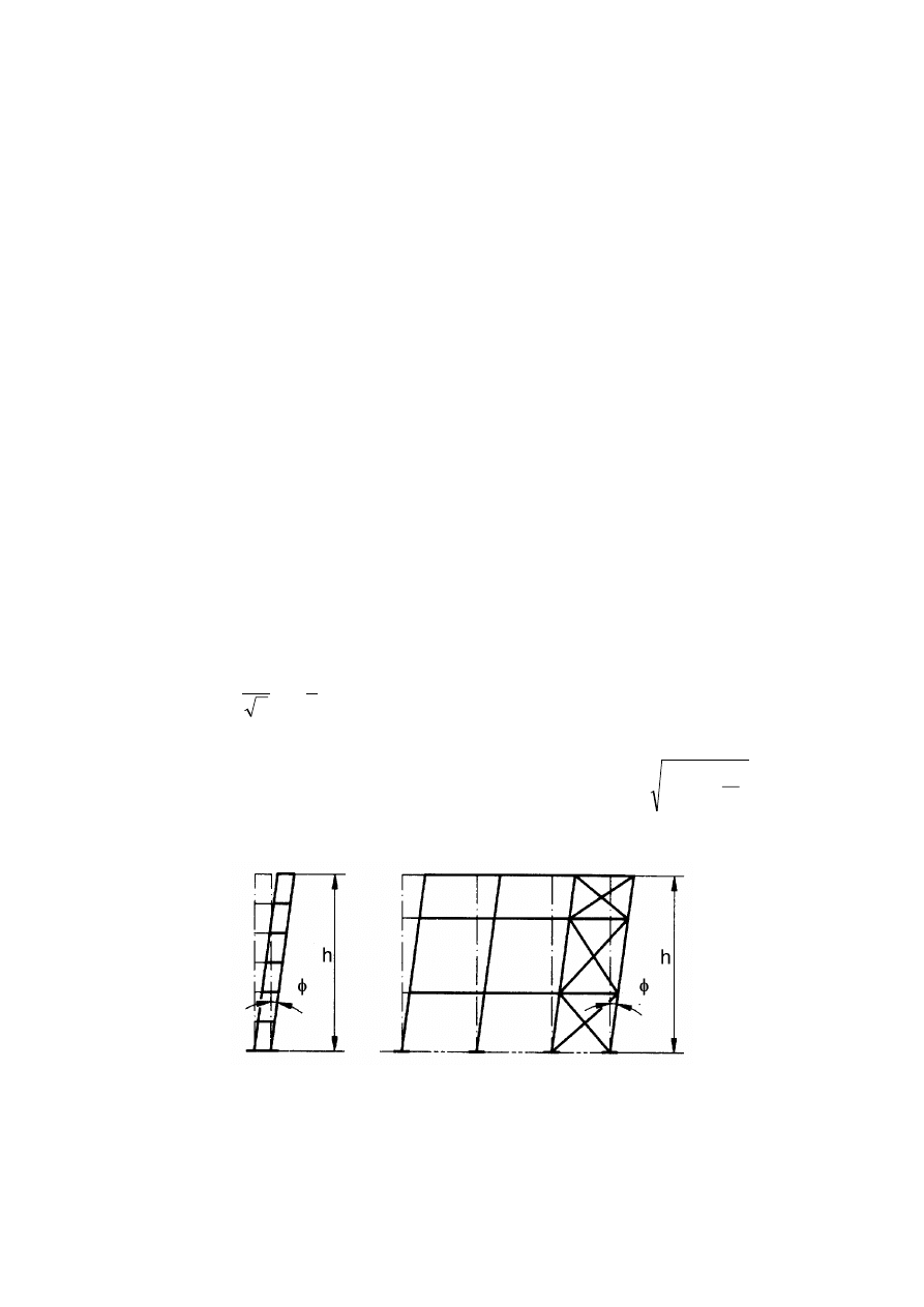
a) global initial sway imperfections, see Figure 5.2:
φ = φ
0
α
h
α
m
(5.5)
where
φ
0
is the basic value:
φ
0
= 1/200
α
h
is the reduction factor for height h applicable to columns:
h
2
h
=
α
but
0
,
1
3
2
h
≤
α
≤
h
is the height of the structure in meters
α
m
is the reduction factor for the number of columns in a row:
+
=
α
m
1
1
5
,
0
m
m
is the number of columns in a row including only those columns which carry a vertical load
N
Ed
not less than 50% of the average value of the column in the vertical plane considered
)LJXUH(TXLYDOHQWVZD\LPSHUIHFWLRQV
b) relative initial local bow imperfections of members for flexural buckling
e
0
/ L
(5.6)
where L is the member length
127( The values e
0
/ L may be chosen in the National Annex. Recommended values are given in
Table 5.1.
3DJH
Final draft
SU(1
7 May 2003
7DEOH'HVLJQYDOXHVRILQLWLDOERZLPSHUIHFWLRQH
/
elastic analysis
plastic analysis
Buckling curve
acc. to Table 6.1
e
0
/ L
e
0
/ L
a
0
1 / 350
1 / 300
a
1 / 300
1 / 250
b
1 / 250
1 / 200
c
1 / 200
1 / 150
d
1 / 150
1 / 100
(4)B For building frames sway imperfections may be disregarded where
H
Ed
≥ 0,15 V
Ed
(5.7)
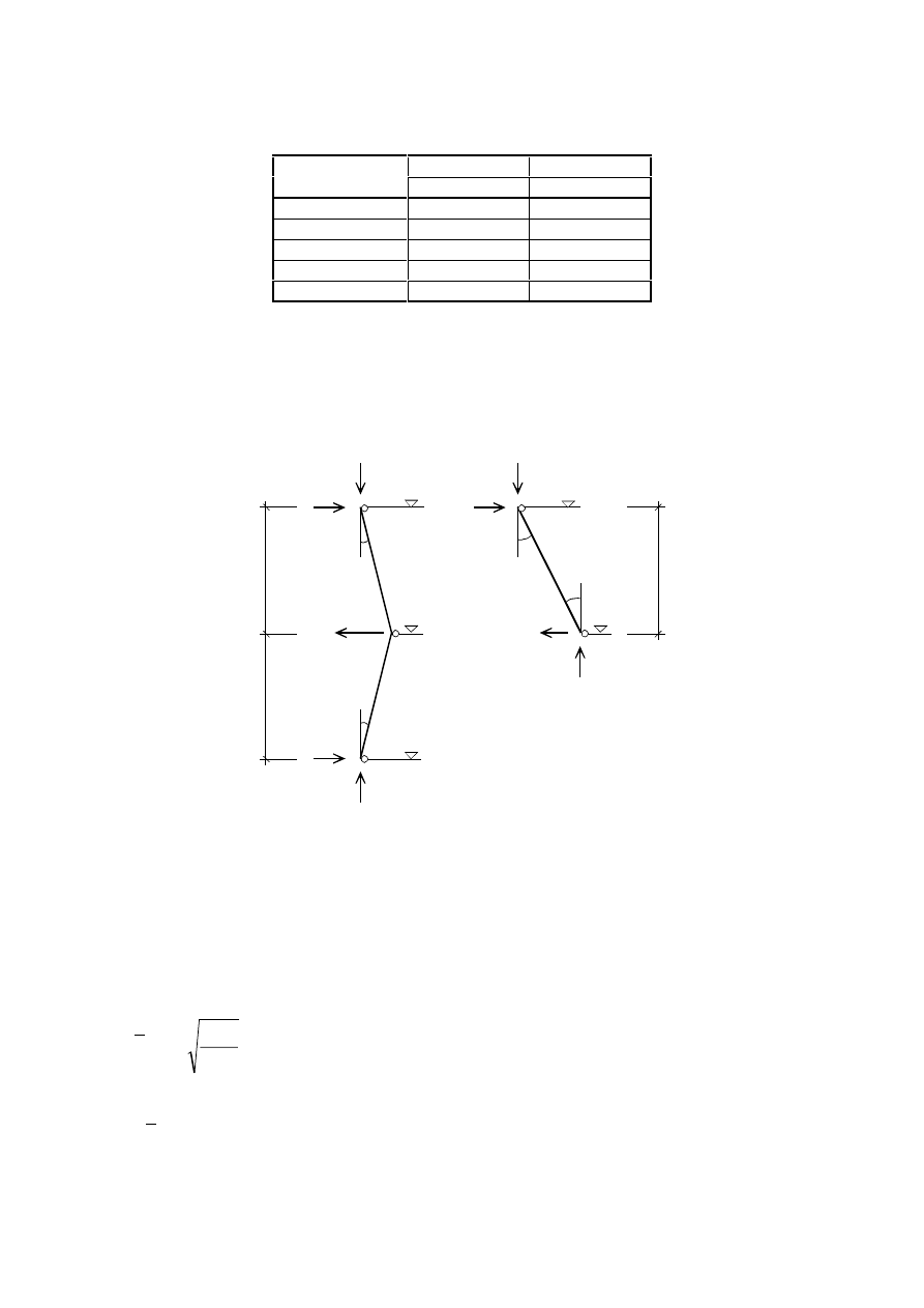
(5)B For the determination of horizontal forces to floor diaphragms the configuration of imperfections as
given in Figure 5.3 should be applied, where
φ is a sway imperfection obtained from (5.5) assuming a single
storey with height h, see (3) a).
N
N
N
/2
N
/2
H
i
=
N
N
Ed
N
Ed
N
Ed
N
Ed
N
Ed
h
h
h
H
i
=
N
N
Ed
)LJXUH&RQILJXUDWLRQRIVZD\LPSHUIHFWLRQVφIRUKRUL]RQWDOIRUFHVRQIORRU
GLDSKUDJPV
(6)
When performing the global analysis for determining end forces and end moments to be used in
member checks according to 6.3 local bow imperfections may be neglected. However for frames sensitive to
second order effects local bow imperfections of members additionally to global sway imperfections (see
5.2.1(3)) should be introduced in the structural analysis of the frame for each compressed member where the
following conditions are met:
–
at least one moment resistant joint at one member end
–
Ed
y
N
f
A
5
,
0
>
λ
(5.8)
where N
Ed
is the design value of the compression force
and
λ
is the in-plane non-dimensional slenderness calculated for the member considered as hinged at
its ends
127( Local bow imperfections are taken into account in member checks, see 5.2.2 (3) and 5.3.4.
Final draft
3DJH
7 May 2003
SU(1
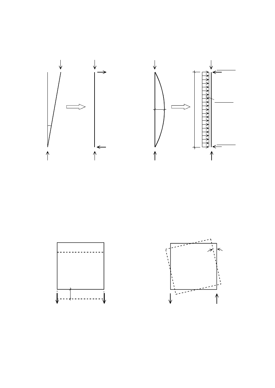
(7)
The effects of initial sway imperfection and bow imperfections may be replaced by systems of
equivalent horizontal forces, introduced for each column, see Figure 5.3 and Figure 5.4.
initial sway imperfections
initial bow imperfections
N
N
Ed
N
Ed
N
Ed
N
Ed
N
N
Ed
N
N
Ed
N
Ed
N
Ed
e
0,d
L
8 N
Ed
e
0,d
L²
4 N
Ed
e
0,d
L
N
Ed
N
Ed
4 N
Ed
e
0,d
L
)LJXUH5HSODFHPHQWRILQLWLDOLPSHUIHFWLRQVE\HTXLYDOHQWKRUL]RQWDOIRUFHV
(8)
These initial sway imperfections should apply in all relevant horizontal directions, but need only be
considered in one direction at a time.
(9)B Where, in multi-storey beam-and-column building frames, equivalent forces are used they should be
applied at each floor and roof level.
(10) The possible torsional effects on a structure caused by anti-symmetric sways at the two opposite faces,
should also be considered, see Figure 5.5.
$
$
%
%
$
$
%
%
(a) Faces A-A and B-B sway
in same direction
(b) Faces A-A and B-B sway
in opposite direction
WUDQVODWLRQDOVZD\
URWDWLRQDOVZD\
)LJXUH7UDQVODWLRQDODQGWRUVLRQDOHIIHFWVSODQYLHZ
3DJH
Final draft
SU(1
7 May 2003
(11) As an alternative to (3) and (6) the shape of the elastic critical buckling mode
η
cr
of the structure may
be applied as a unique global and local imperfection. The amplitude of this imperfection may be determined
from:
cr
"
max
,
cr
Rk
d
,
0
init
EI
M
e
η
η
=
η
(5.9)
where:
(
)
2
,
0
for
1
1
2
,
0
e
2
1
M
2
2
d
,
0
>
λ
λ
χ
−
γ
λ
χ
−
λ
−
λ
α
=
(5.10)
and
cr
k
,
ult
α
α
=
λ
is the relative slenderness of the structure
(5.11)
is the imperfection factor for the relevant buckling curve, see Table 6.1 and Table 6.2;
is the reduction factor for the relevant buckling curve depending on the relevant cross-section, see
6.3.1;
ult,k
is the minimum force amplifier for the axial force configuration N
Ed
in members to reach the
characteristic resistance N
Rk
of the most axially stressed cross section without taking buckling
into account
cr
is the minimum force amplifier for the axial force configuration N
Ed
in members to reach the
elastic critical buckling
M
Rk
is the characteristic moments resistance of the critical cross section, e.g M
el,Rk
or M
pl,Rk
as relevant
"
cr
EI
η
is the bending moment due to
η
cr
at the critical cross section
127( For calculating the amplifiers α
ult,k
and
α
cr
the members of the structure may be considered
to be loaded by axial forces N
Ed
only that result from the first order elastic analysis of the structure for
the design loads.
127( The National Annex may give informations for the scope of application of (11).
,PSHUIHFWLRQIRUDQDO\VLVRIEUDFLQJV\VWHPV
(1)
In the analysis of bracing systems which are required to provide lateral stability within the length of
beams or compression members the effects of imperfections should be included by means of an equivalent
geometric imperfection of the members to be restrained, in the form of an initial bow imperfection:
e
0
=
α
m
L / 500
(5.12)
where L is the span of the bracing system
and
+
=
α
m
1
1
5
,
0
m
in which m is the number of members to be restrained.
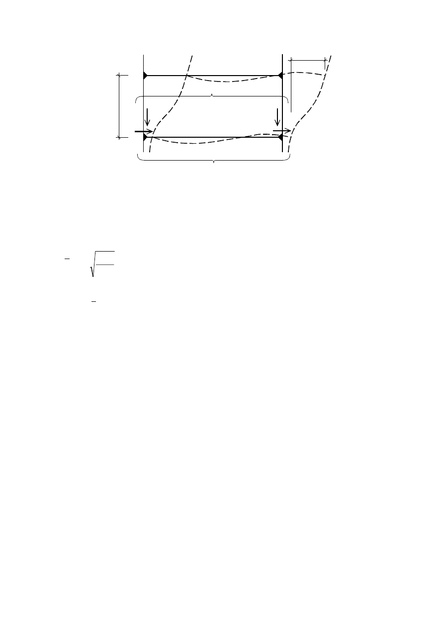
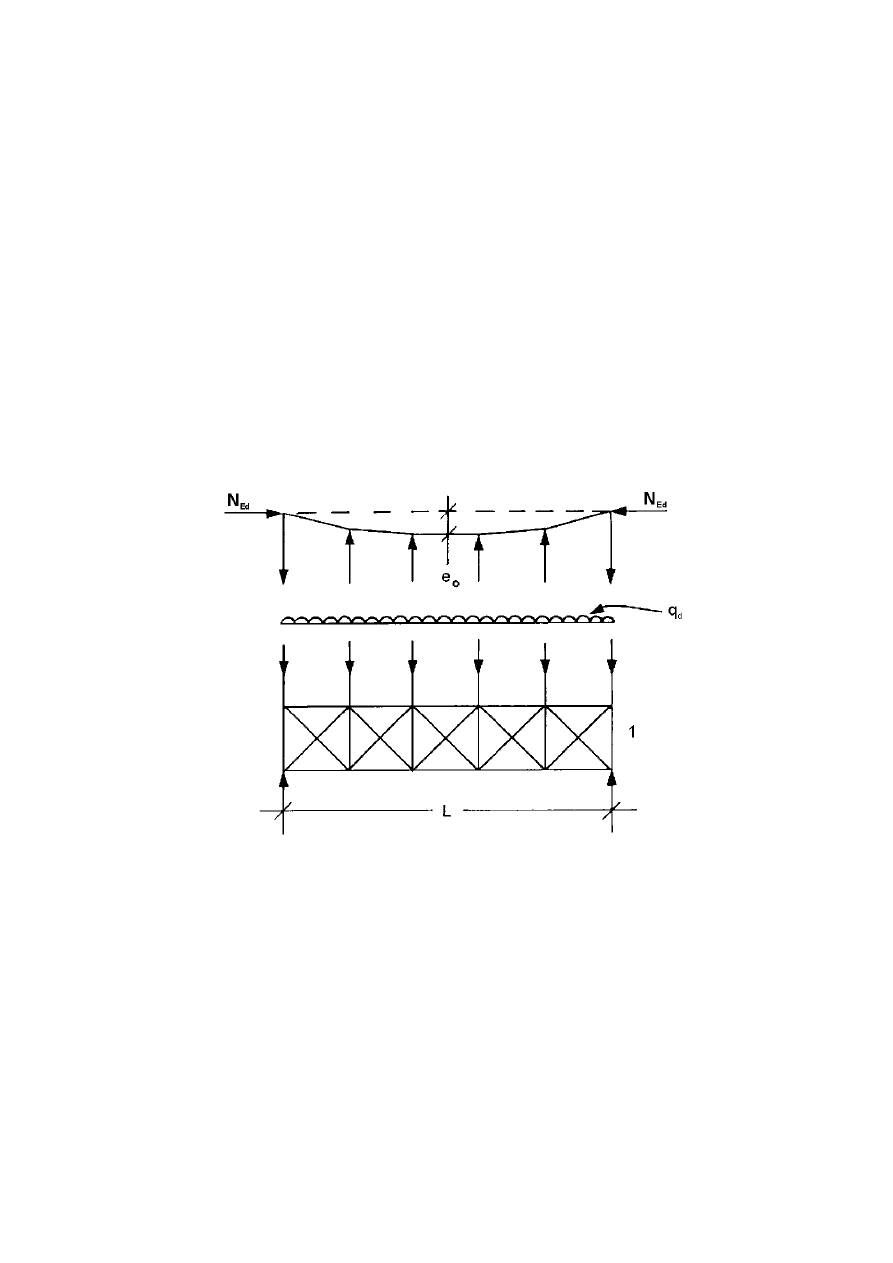
(2)
For convenience, the effects of the initial bow imperfections of the members to be restrained by a
bracing system, may be replaced by the equivalent stabilising force as shown in Figure 5.6:
∑
δ
+
=
2
q
0
Ed
L
e
8
N
q
(5.13)
where
δ
q
is the inplane deflection of the bracing system due to q plus any external loads calculated from
first order analysis
Final draft
3DJH
7 May 2003
SU(1
127( δ
q
may be taken as 0 if second order theory is used.
(3)
Where the bracing system is required to stabilise the compression flange of a beam of constant height,
the force N
Ed
in Figure 5.6 may be obtained from:
N
Ed
= M
Ed
/ h
(5.14)
where M
Ed
is the maximum moment in the beam
and
h
is the overall depth of the beam.
127( Where a beam is subjected to external compression N
Ed
should include a part of the
compression force.
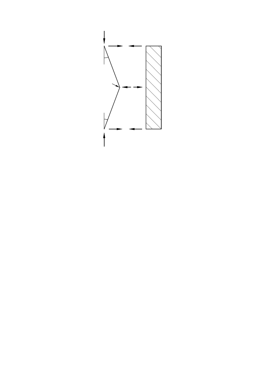
(4)
At points where beams or compression members are spliced, it should also be verified that the bracing
system is able to resist a local force equal to
α
m
N
Ed
/ 100 applied to it by each beam or compression member
which is spliced at that point, and to transmit this force to the adjacent points at which that beam or
compression member is restrained, see Figure 5.7.
(5)
For checking for the local force according to clause (4), any external loads acting on bracing systems
should also be included, but the forces arising from the imperfection given in (1) may be omitted.
H
LPSHUIHFWLRQ
T
HTXLYDOHQWIRUFHSHUXQLWOHQJWK
EUDFLQJV\VWHP
The force N
Ed
is assumed uniform within the span L of the bracing system.
For non-uniform forces this is slightly conservative.
)LJXUH(TXLYDOHQWVWDELOLVLQJIRUFH
3DJH
Final draft
SU(1
7 May 2003
N
Ed
Ed
Ed
Ed
Ed
N
N
N
Φ
Φ
Φ
Φ
Φ
2 N
1
2
Φ = α
m
Φ
0
:
Φ
0
= 1 / 200
2
ΦN
Ed
=
α
m
N
Ed
/ 100
VSOLFH
EUDFLQJV\VWHP
)LJXUH%UDFLQJIRUFHVDWVSOLFHVLQFRPSUHVVLRQHOHPHQWV
0HPEHULPSHUIHFWLRQV
(1)
The effects of imperfections of members are incorporated within the formulas given for buckling
resistance for members, see section 6.3.
(2)
Where the stability of members is accounted for by second order analysis according to 5.2.2(5)a) for
compression members imperfections e
0,d
according to 5.3.2(3)b) or 5.3.2(5) or (6) should be considered.
(3)
For a second order analysis taking account of lateral torsional buckling of a member in bending the
imperfections may be adopted as ke
0,d
, where e
0,d
is the equivalent initial bow imperfection of the weak axis
of the profile considered. In general an additional torsional imperfection need not to be allowed for.
127( The National Annex may choose the value of k. The value k = 0,5 is recommended.
0HWKRGVRIDQDO\VLVFRQVLGHULQJPDWHULDOQRQOLQHDULWLHV
*HQHUDO
(1)
The internal forces and moments may be determined using either
a) elastic global analysis
b) plastic global analysis.
127( For finite element model (FEM) analysis see EN 1993-1-5.
(2)
Elastic global analysis may be used in all cases.
Final draft
3DJH
7 May 2003
SU(1
(3)
Plastic global analysis may be used only where the structure has sufficient rotation capacity at the
actual location of the plastic hinge, whether this is in the members or in the joints. Where a plastic hinge
occurs in a member, the member cross sections should be double symmetric or single symmetric with a plane
of symmetry in the same plane as the rotation of the plastic hinge and it should satisfy the requirements
specified in 5.6. Where a plastic hinge occurs in a joint the joint should either have sufficient strength to
ensure the hinge remains in the member or should be able to sustain the plastic resistance for a sufficient
rotation, see EN 1993-1-8.
(4)B As a simplified method for a limited plastic redistribution of moments in continuous beams where
following an elastic analysis some peak moments exceed the plastic bending resistance of 15 % maximum,
the parts in excess of these peak moments may be redistributed in any member, provided, that:
a) the internal forces and moments in the frame remain in equilibrium with the applied loads, and
b) all the members in which the moments are reduced have Class 1 or Class 2 cross-sections (see 5.5), and
c) lateral torsional buckling of the members is prevented.
(ODVWLFJOREDODQDO\VLV
(1)
Elastic global analysis shall be based on the assumption that the stress-strain behaviour of the material
is linear, whatever the stress level is.
127( For the choice of a semi-continuous joint model see 5.1.2(2) to (4).
(2)
Internal forces and moments may be calculated according to elastic global analysis even if the
resistance of a cross section is based on its plastic resistance, see 6.2.
(3)
Elastic global analysis may also be used for cross sections the resistances of which are limited by local
buckling, see 6.2.
3ODVWLFJOREDODQDO\VLV
(1)
Plastic global analysis allows for the effects of material non-linearity in calculating the action effects
of a structural system. The behaviour should be modelled by one of the following methods:
–
by elastic-plastic analysis with plastified sections and/or joints as plastic hinges,
–
by non-linear plastic analysis considering the partial plastification of members in plastic zones,
–
by rigid plastic analysis neglecting the elastic behaviour between hinges.
(2)
Plastic global analysis may be used where the members are capable of sufficient rotation capacity to
enable the required redistributions of bending moments to develop, see 5.5 and 5.6.
(3)
Plastic global analysis should only be used where the stability of members at plastic hinges can be
assured, see 6.3.5.
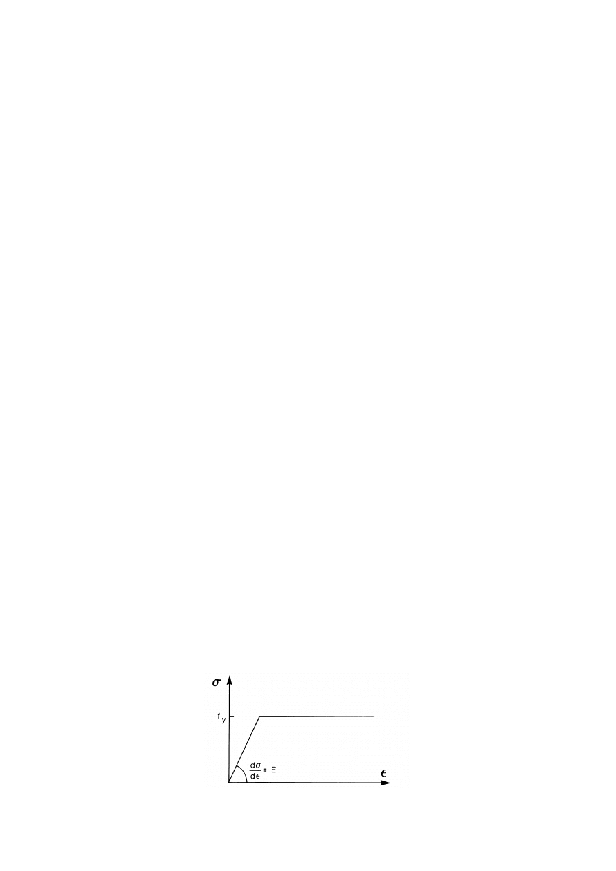
(4)
The bi-linear stress-strain relationship indicated in Figure 5.8 may be used for the grades of structural
steel specified in section 3. Alternatively, a more precise relationship may be adopted, see EN 1993-1-5.
)LJXUH%LOLQHDUVWUHVVVWUDLQUHODWLRQVKLS

3DJH
Final draft
SU(1
7 May 2003
(5)
Rigid plastic analysis may be applied if no effects of the deformed geometry (e.g. second-order
effects) have to be considered. In this case joints are classified only by strength, see EN 1993-1-8.
(6)
The effects of deformed geometry of the structure and the structural stability of the frame should be
verified according to the principles in 5.2.
127( The maximum resistance of a frame with significantly deformed geometry may occur before
all hinges of the first order collapse mechanism have formed.
&ODVVLILFDWLRQRIFURVVVHFWLRQV
%DVLV
(1)
The role of cross section classification is to identify the extent to which the resistance and rotation
capacity of cross sections is limited by its local buckling resistance.
&ODVVLILFDWLRQ
(1)
Four classes of cross-sections are defined, as follows:
–
Class 1 cross-sections are those which can form a plastic hinge with the rotation capacity required from
plastic analysis without reduction of the resistance.
–
Class 2 cross-sections are those which can develop their plastic moment resistance, but have limited
rotation capacity because of local buckling.
–
Class 3 cross-sections are those in which the stress in the extreme compression fibre of the steel member
assuming an elastic distribution of stresses can reach the yield strength, but local buckling is liable to
prevent development of the plastic moment resistance.
–
Class 4 cross-sections are those in which local buckling will occur before the attainment of yield stress in
one or more parts of the cross-section.
(2)
In Class 4 cross sections effective widths may be used to make the necessary allowances for
reductions in resistance due to the effects of local buckling, see EN 1993-1-5, 5.2.2.
(3)
The classification of a cross-section depends on the width to thickness ratio of the parts subject to
compression.
(4)
Compression parts include every part of a cross-section which is either totally or partially in
compression under the load combination considered.
(5)
The various compression parts in a cross-section (such as a web or flange) can, in general, be in
different classes.
(6)
A cross-section is classified according to the highest (least favourable) class of its compression parts.
Exceptions are specified in 6.2.1(10) and 6.2.2.4(1).
(7)
Alternatively the classification of a cross-section may be defined by quoting both the flange
classification and the web classification.
(8)
The limiting proportions for Class 1, 2, and 3 compression parts should be obtained from Table 5.2. A
part which fails to satisfy the limits for Class 3 should be taken as Class 4.
(9)
Except as given in (10) Class 4 sections may be treated as Class 3 sections if the width to thickness
ratios are less than the limiting proportions for Class 3 obtained from Table 5.2 when
ε is increased by
Ed
,
com
0
M
y
/
f
σ
γ
, where
Ed
,
com
σ
is the maximum design compressive stress in the part taken from first order or
where necessary second order analysis.

Final draft
3DJH
7 May 2003
SU(1
(10) However, when verifying the design buckling resistance of a member using section 6.3, the limiting
proportions for Class 3 should always be obtained from Table 5.2.
(11) Cross-sections with a Class 3 web and Class 1 or 2 flanges may be classified as class 2 cross sections
with an effective web in accordance with 6.2.2.3.
(12) Where the web is considered to resist shear forces only and is assumed not to contribute to the bending
and normal force resistance of the cross section, the cross section may be designed as Class 2, 3 or 4
sections, depending only on the flange class.
127( For flange induced web buckling see EN 1993-1-5.
&URVVVHFWLRQUHTXLUHPHQWVIRUSODVWLFJOREDODQDO\VLV
(1)
At plastic hinge locations, the cross-section of the member which contains the plastic hinge shall have
a rotation capacity of not less than the required at the plastic hinge location.
(2)
In a uniform member sufficient rotation capacity may be assumed at a plastic hinge if both the
following requirements are satisfied:
a) the member has Class 1 cross-sections at the plastic hinge location;
b) where a transverse force that exceeds 10 % of the shear resistance of the cross section, see 6.2.6, is
applied to the web at the plastic hinge location, web stiffeners should be provided within a distance along
the member of h/2 from the plastic hinge location, where h is the height of the cross section at this
location.
(3)
Where the cross-section of the member vary along their length, the following additional criteria should
be satisfied:
a) Adjacent to plastic hinge locations, the thickness of the web should not be reduced for a distance each
way along the member from the plastic hinge location of at least 2d, where d is the clear depth of the web
at the plastic hinge location.
b) Adjacent to plastic hinge locations, the compression flange should be Class 1 for a distance each way
along the member from the plastic hinge location of not less than the greater of:
–
2d, where d is as defined in (3)a)
–
the distance to the adjacent point at which the moment in the member has fallen to 0,8 times the
plastic moment resistance at the point concerned.
c) Elsewhere in the member the compression flange should be class 1 or class 2 and the web should be class
1, class 2 or class 3.
(4)
Adjacent to plastic hinge locations, any fastener holes in tension should satisfy 6.2.5(4) for a distance
such as defined in (3)b) each way along the member from the plastic hinge location.
(5)
For plastic design of a frame, regarding cross section requirements, the capacity of plastic
redistribution of moments may be assumed sufficient if the requirements in (2) to (4) are satisfied for all
members where plastic hinges exist, may occur or have occurred under design loads.
(6)
In cases where methods of plastic global analysis are used which consider the real stress and strain
behaviour along the member including the combined effect of local, member and global buckling the
requirements (2) to (5) need not be applied.
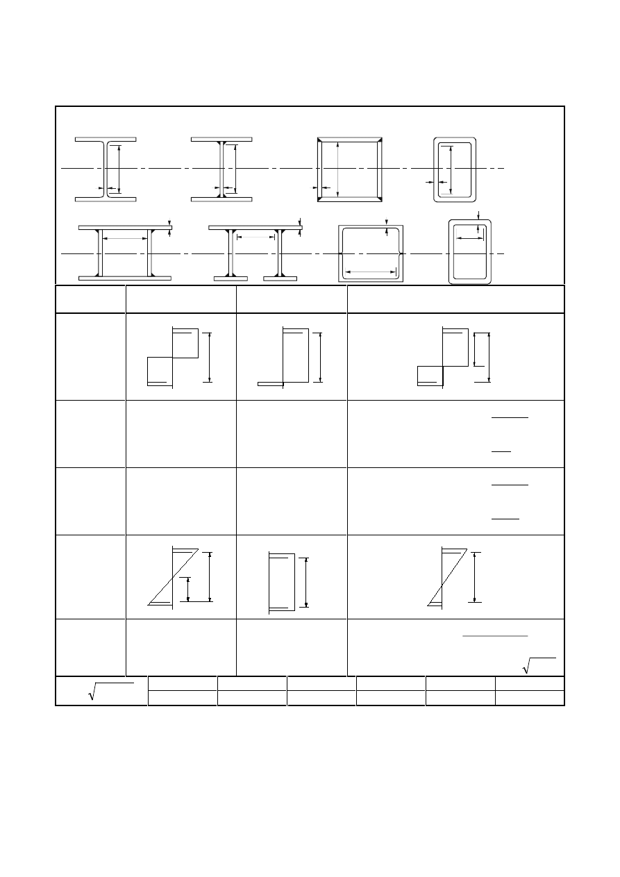
3DJH
Final draft
SU(1
7 May 2003
7DEOHVKHHWRI0D[LPXPZLGWKWRWKLFNQHVVUDWLRVIRUFRPSUHVVLRQ
SDUWV
,QWHUQDOFRPSUHVVLRQSDUWV
t
c
t
c
c
t
c
t
Axis of
bending
c
t
t
c
t
c
t
c
Axis of
bending
Class
Part subject to
bending
Part subject to
compression
Part subject to bending and compression
Stress
distribution
in parts
(compression
positive)
+
f
y
-
f
y
c
+
f
y
-
f
y
c
+
f
y
-
f
y
c
α
c
1
ε
≤ 72
t
/
c
ε
≤ 33
t
/
c
α
ε
≤
≤
α
−
α
ε
≤
>
α
36
t
/
c
:
5
,
0
when
1
13
396
t
/
c
:
5
,
0
when
2
ε
≤ 83
t
/
c
ε
≤ 38
t
/
c
α
ε
≤
≤
α
−
α
ε
≤
>
α
5
,
41
t
/
c
:
5
,
0
when
1
13
456
t
/
c
:
5
,
0
when
Stress
distribution
in parts
(compression
positive)
+
f
y
-
f
y
c
c/
2
+
f
y
c
+
f
y
-
ψ
f
y
c
3
ε
≤ 124
t
/
c
ε
≤ 42
t
/
c
)
(
)
1
(
62
t
/
c
:
1
when
33
,
0
67
,
0
42
t
/
c
:
1
when
*)
ψ
−
ψ
−
ε
≤
−
≤
ψ
ψ
+
ε
≤
−
>
ψ
f
y
235
275
355
420
460
y
f
/
235
=
ε
ε
1,00
0,92
0,81
0,75
0,71
*)
ψ ≤ -1 applies where either the compression stress σ < f
y
or the tensile strain
ε
y
> f
y
/E
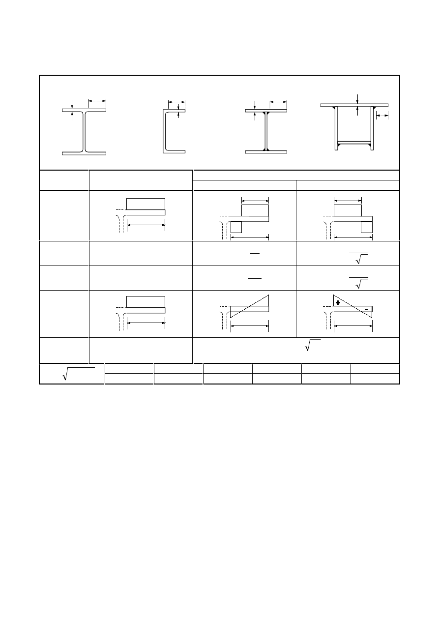
Final draft
3DJH
7 May 2003
SU(1
7DEOHVKHHWRI0D[LPXPZLGWKWRWKLFNQHVVUDWLRVIRUFRPSUHVVLRQ
SDUWV
2XWVWDQGIODQJHV
t
c
t
c
t
c
t
c
Rolled sections
Welded sections
Part subject to bending and compression
Class
Part subject to compression
Tip in compression
Tip in tension
Stress
distribution
in parts
(compression
positive)
+
c
α
c
+
c
-
α
c
+
c
-
1
ε
≤ 9
t
/
c
α
ε
≤
9
t
/
c
α
α
ε
≤
9
t
/
c
2
ε
≤ 10
t
/
c
α
ε
≤
10
t
/
c
α
α
ε
≤
10
t
/
c
Stress
distribution
in parts
(compression
positive)
+
c
+
c
-
c
3
ε
≤ 14
t
/
c
σ
ε
≤
k
21
t
/
c
For k
σ
see EN 1993-1-5
f
y
235
275
355
420
460
y
f
/
235
=
ε
ε
1,00
0,92
0,81
0,75
0,71
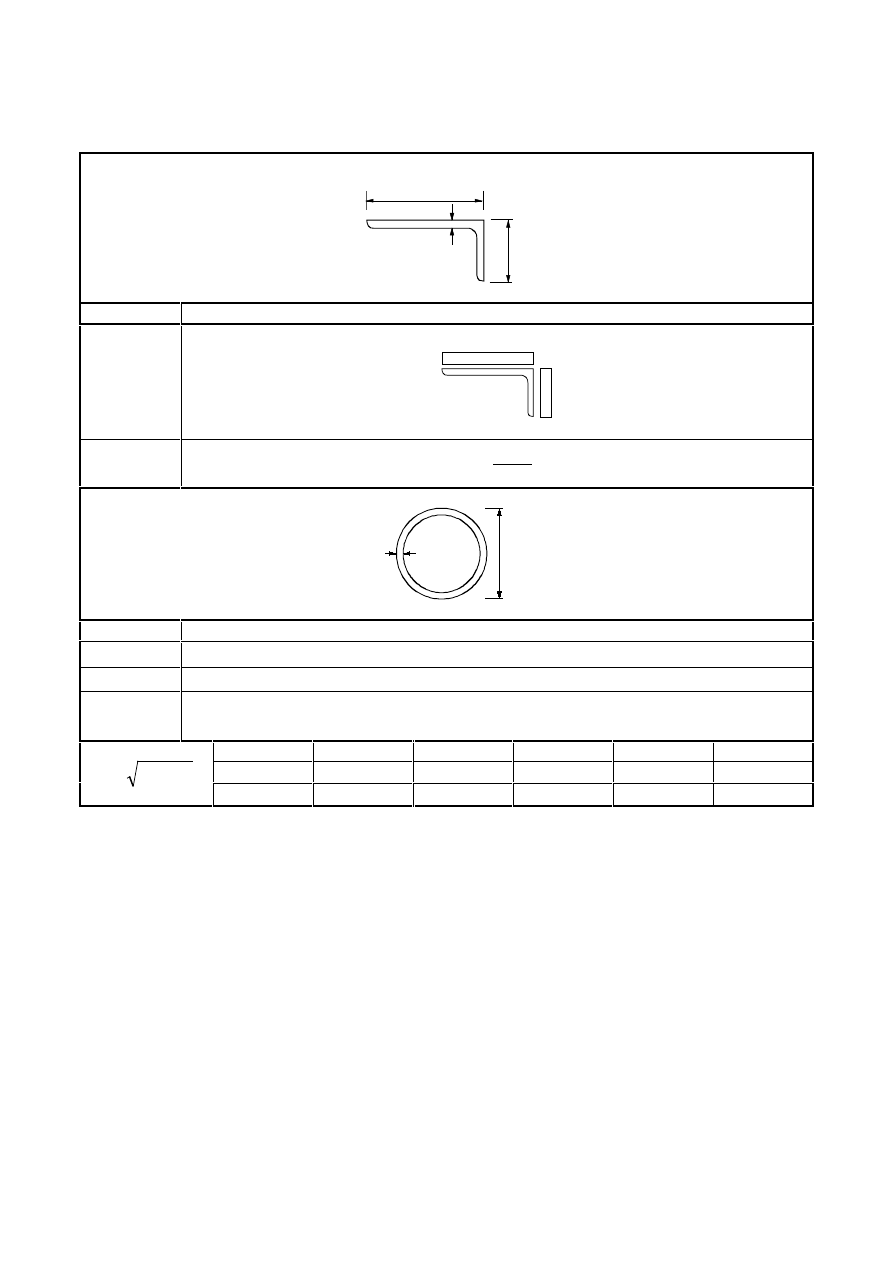
3DJH
Final draft
SU(1
7 May 2003
7DEOHVKHHWRI0D[LPXPZLGWKWRWKLFNQHVVUDWLRVIRUFRPSUHVVLRQ
SDUWV
Refer also to “Outstand flanges”
(see sheet 2 of 3)
$QJOHV
t
h
b
Does not apply to angles in
continuous contact with other
components
Class
Section in compression
Stress
distribution
across
section
(compression
positive)
+
+
f
y
3
ε
≤
+
ε
≤
5
,
11
t
2
h
b
:
15
t
/
h
7XEXODUVHFWLRQV
t
d
Class
Section in bending and/or compression
1
2
50
t
/
d
ε
≤
2
2
70
t
/
d
ε
≤
3
2
90
t
/
d
ε
≤
127( For
2
90
t
/
d
ε
>
see EN 1993-1-6.
f
y
235
275
355
420
460
ε
1,00
0,92
0,81
0,75
0,71
y
f
/
235
=
ε
ε
2
1,00
0,85
0,66
0,56
0,51

Final draft
3DJH
7 May 2003
SU(1
8OWLPDWHOLPLWVWDWHV
*HQHUDO
(1)
The partial factors
γ
M
as defined in 2.4.3 should be applied to the various characteristic values of
resistance in this section as follows:
–
resistance of cross-sections whatever the class is:
γ
M0
–
resistance of members to instability assessed by member checks:
γ
M1
–
resistance of cross-sections in tension to fracture:
γ
M2
–
resistance of joints:
see EN 1993-1-8
127( % Partial factors γ
Mi
for buildings may be defined in the National Annex. The following
numerical values are recommended for buildings:
γ
M0
= 1,00
γ
M1
= 1,00
γ
M2
= 1,25
127(For other recommended numerical values see EN 1993 Part 2 to Part 6. For structures not
covered by EN 1993 Part 2 to Part 6 the National Annex may give information.
5HVLVWDQFHRIFURVVVHFWLRQV
*HQHUDO
(1)
The design value of an action effect in each cross section shall not exceed the corresponding design
resistance and if several action effects act simultaneously the combined effect shall not exceed the resistance
for that combination.
(2)
Shear lag effects and local buckling effects should be included by an effective width according to
EN 1993-1-5. Shear buckling effects should also be considered according to EN 1993-1-5.
(3)
The design values of resistance should depend on the classification of the cross-section.
(4)
Elastic verification according to the elastic resistance may be carried out for all cross sectional classes
provided the effective cross sectional properties are used for the verification of class 4 cross sections.
(5)
For the elastic verification the following yield criterion for a critical point of the cross section may be
used unless other interaction formulae apply, see 6.2.8 to 6.2.10.
1
f
3
f
f
f
f
2
0
M
y
Ed
0
M
y
Ed
,
z
0
M
y
Ed
,
x
2
0
M
y
Ed
,
z
2
0
M
y
Ed
,
x
≤
γ
τ
+
γ
σ
γ
σ
−
γ
σ
+
γ
σ
(6.1)
where
Ed
,
x
σ
is the design value of the local longitudinal stress at the point of consideration
Ed
,
z
σ
is the design value of the local transverse stress at the point of consideration
Ed
τ
is the design value of the local shear stress at the point of consideration
127( The verification according to (5) can be conservative as it excludes partial plastic stress
distribution, which is permitted in elastic design. Therefore it should only be performed where the
interaction of on the basis of resistances N
Rd
, M
Rd
, V
Rd
cannot be performed.

3DJH
Final draft
SU(1
7 May 2003
(6)
The plastic resistance of cross sections should be verified by finding a stress distribution which is in
equilibrium with the internal forces and moments without exceeding the yield strength. This stress
distribution should be compatible with the associated plastic deformations.
(7)
As a conservative approximation for all cross section classes a linear summation of the utilisation
ratios for each stress resultant may be used. For class 1, class 2 or class 3 cross sections subjected to the
combination of N
Ed
, M
y,Ed
and M
z,Ed
this method may be applied by using the following criteria:
1
M
M
M
M
N
N
Rd
,
z
Ed
,
z
Rd
,
y
Ed
,
y
Rd
Ed
≤
+
+
(6.2)
where N
Rd
, M
y,Rd
and M
z,Rd
are the design values of the resistance depending on the cross sectional
classification and including any reduction that may be caused by shear effects, see 6.2.8.
127( For class 4 cross sections see 6.2.9.3(2).
(8)
Where all the compression parts of a cross-section are Class 2, the cross-section may be taken as
capable of developing its full plastic resistance in bending.
(9)
Where all the compression parts of a cross-section are Class 3, its resistance should be based on an
elastic distribution of strains across the cross-section. Compressive stresses should be limited to the yield
strength at the extreme fibres.
127( The extreme fibres may be assumed at the midplane of the flanges for ULS checks. For
fatigue see EN 1993-1-9.
(10) Where yielding first occurs on the tension side of the cross section, the plastic reserves of the tension
zone may be utilised by accounting for partial plastification when determining the resistance of a Class 3
cross-section.
6HFWLRQSURSHUWLHV
*URVVFURVVVHFWLRQ
(1)
The properties of the gross cross-section shall be determined using the nominal dimensions. Holes for
fasteners need not be deducted, but allowance shall be made for larger openings. Splice materials shall not be
included.
1HWDUHD
(1)
The net area of a cross-section shall be taken as its gross area less appropriate deductions for all holes
and other openings.
(2)
For calculating net section properties, the deduction for a single fastener hole should be the gross
cross-sectional area of the hole in the plane of its axis. For countersunk holes, appropriate allowance should
be made for the countersunk portion.
(3)
Provided that the fastener holes are not staggered, the total area to be deducted for fastener holes
should be the maximum sum of the sectional areas of the holes in any cross-section perpendicular to the
member axis (see failure plane
➁ in Figure 6.1).
127( The maximum sum denotes the position of the critical fracture line.
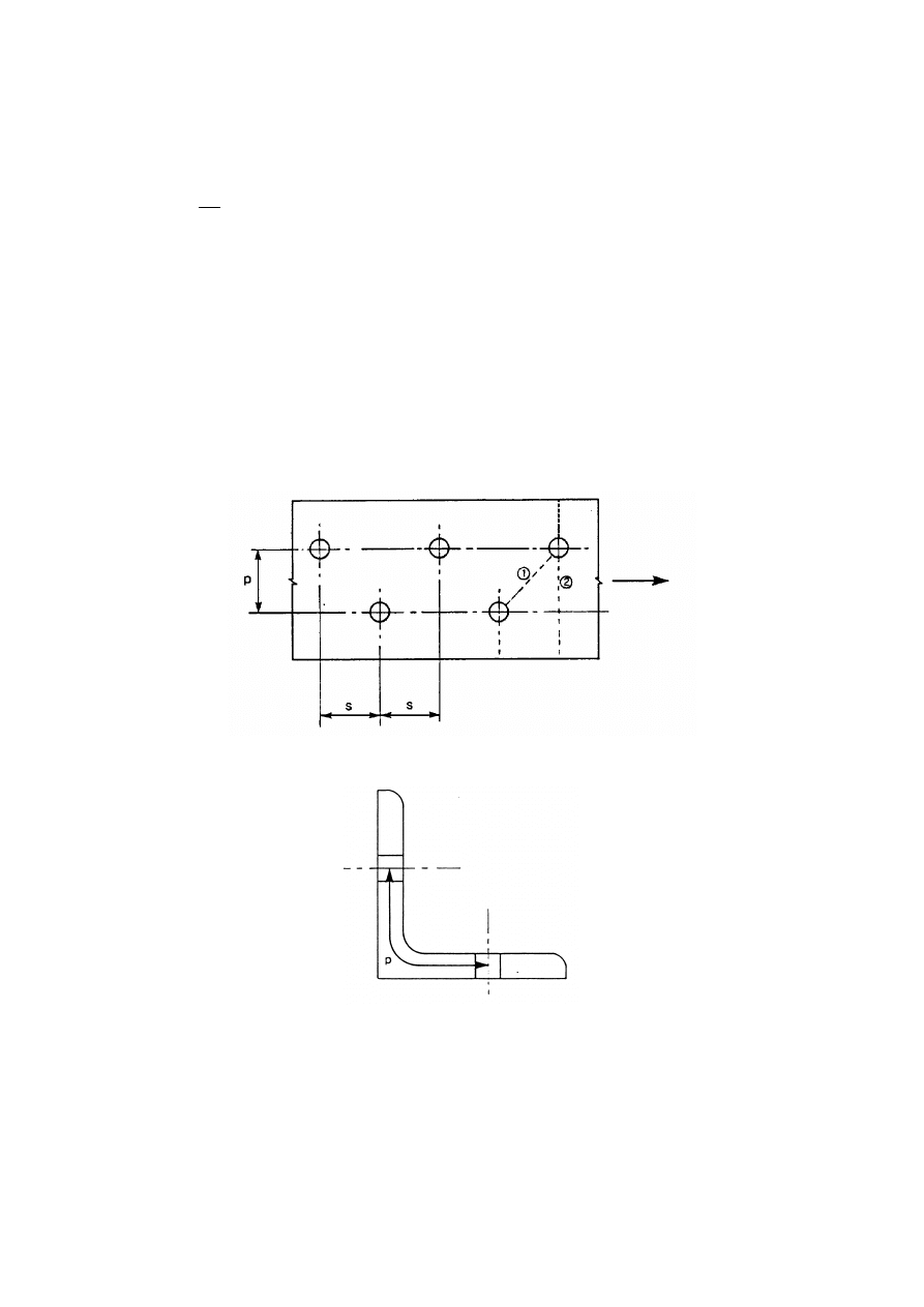
Final draft
3DJH
7 May 2003
SU(1
(4)
Where the fastener holes are staggered, the total area to be deducted for fasteners shall be the greater
of:
a) the deduction for non-staggered holes given in (3)
b)
−
∑
p
4
s
nd
t
2
(6.3)
where s is the staggered pitch, the spacing of the centres of two consecutive holes in the chain measured
parallel to the member axis;
p is the spacing of the centres of the same two holes measured perpendicular to the member axis;
t
is the thickness;
n is the number of holes extending in any diagonal or zig-zag line progressively across the member
or part of the member, see Figure 6.1.
d is the diameter of hole
(5)
In an angle or other member with holes in more then one plane, the spacing p shall be measured along
the centre of thickness of the material (see Figure 6.2).
)LJXUH6WDJJHUHGKROHVDQGFULWLFDOIUDFWXUHOLQHVDQG
)LJXUH$QJOHVZLWKKROHVLQERWKOHJV
6KHDUODJHIIHFWV
(1)
The calculation of the effective widths is covered in EN 1993-1-5.
(2)
In class 4 sections the interaction between shear lag and local buckling shall be considered according
to EN 1993-1-5.
127( For cold formed thin gauge members see EN 1993-1-3.
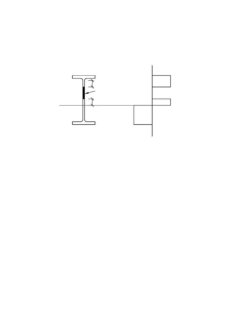
3DJH
Final draft
SU(1
7 May 2003
(IIHFWLYHSURSHUWLHVRIFURVVVHFWLRQVZLWKFODVVZHEVDQGFODVVRUIODQJHV
(1)
Where cross-sections with a class 3 web and class 1 or 2 flanges are classified as effective Class 2
cross-sections, see 5.5.2(11), the proportion of the web in compression should be replaced by a part of 20
εt
w
adjacent to the compression flange, with another part of 20
εt
w
adjacent to the plastic neutral axis of the
effective cross-section in accordance with Figure 6.3.
-
-
+
2
2
f
f
1
1
4
3
20
20
ε
ε
t
t
w
w
y
y
FRPSUHVVLRQ
WHQVLRQ
SODVWLFQHXWUDOD[LV
QHJOHFW
)LJXUH(IIHFWLYHFODVVZHE
(IIHFWLYHFURVVVHFWLRQSURSHUWLHVRI&ODVVFURVVVHFWLRQV
(1)
The effective cross-section properties of Class 4 cross-sections should be based on the effective widths
of the compression parts.
(2)
For cold formed thin walled sections see 1.1.2(1) and EN 1993-1-3.
(3)
The effective widths of planar compression parts should be obtained from EN 1993-1-5.
(4)
Where a class 4 cross section is subjected to an axial force, the method given in EN 1993-1-5 should
be used to determine the possible shift e
N
of the centroid of the effective area A
eff
relative to the centre of
gravity of the gross cross section and the resulting additional moment:
N
Ed
Ed
e
N
M
=
∆
(6.4)
127( The sign of the additional moment depends on the effect in the combination of internal forces
and moments, see 6.2.9.3(2).
(5)
For circular hollow sections with class 4 cross sections see EN 1993-1-6.

Final draft
3DJH
7 May 2003
SU(1
7HQVLRQ
(1)
The design value of the tension force N
Ed
at each cross section shall satisfy:
0
,
1
N
N
Rd
,
t
Ed
≤
(6.5)
(2)
For sections with holes the design tension resistance N
t,Rd
should be taken as the smaller of:
a) the design plastic resistance of the gross cross-section
0
M
y
Rd
,
pl
f
A
N
γ
=
(6.6)
b) the design ultimate resistance of the net cross-section at holes for fasteners
2
M
u
net
Rd
,
u
f
A
0,9
N
γ
=
(6.7)
(3)
Where capacity design is requested, see EN 1998, the design plastic resistance N
pl,Rd
(as given in
6.2.3(2) a)) should be less than the design ultimate resistance of the net section at fasteners holes N
u,Rd
(as
given in 6.2.3(2) b)).
(4)
In category C connections (see EN 1993-1-8, 3.1.1(4)), the design tension resistance N
t,Rd
in 6.2.3(1)
of the net section at holes for fasteners should be taken as N
net,Rd
, where:
0
M
y
net
Rd
,
net
f
A
N
γ
=
(6.8)
(5)
For angles connected through one leg, see also EN 1993-1-8, 3.6.3. Similar consideration should also
be given to other type of sections connected through outstands.
&RPSUHVVLRQ
(1)
The design value of the compression force N
Ed
at each cross-section shall satisfy:
0
,
1
N
N
Rd
,
c
Ed
≤
(6.9)
(2)
The design resistance of the cross-section for uniform compression N
c,Rd
shall be determined as
follows:
0
M
y
Rd
,
c
f
A
N
γ
=
for class 1, 2 or 3 cross-sections
(6.10)
0
M
y
eff
Rd
,
c
f
A
N
γ
=
for class 4 cross-sections
(6.11)
(3)
Fastener holes except for oversize and slotted holes as defined in EN 1090 need not be allowed for in
compression members, provided that they are filled by fasteners.
(4)
In the case of unsymmetrical Class 4 sections, the method given in 6.2.9.3 should be used to allow for
the additional moment
∆M
Ed
due to the eccentricity of the centroidal axis of the effective section, see
6.2.2.5(4).
3DJH
Final draft
SU(1
7 May 2003
%HQGLQJPRPHQW
(1)
The design value of the bending moment M
Ed
at each cross-section shall satisfy:
0
,
1
M
M
Rd
,
c
Ed
≤
(6.12)
where M
c,Rd
is determined considering fastener holes, see (4) to (6).
(2)
The design resistance for bending about one principal axis of a cross-section is determined as follows:
0
M
y
pl
Rd
,
pl
Rd
,
c
f
W
M
M
γ
=
=
for class 1 or 2 cross sections
(6.13)
0
M
y
min
,
el
Rd
,
el
Rd
,
c
f
W
M
M
γ
=
=
for class 3 cross sections
(6.14)
0
M
y
min
,
eff
Rd
,
c
f
W
M
γ
=
for class 4 cross sections
(6.15)
where W
el,min
and W
eff,min
corresponds to the fibre with the maximum elastic stress.
(3)
For bending about both axes, the methods given in 6.2.9 should be used.
(4)
Fastener holes in the tension flange may be ignored provided that for the tension flange:
0
M
y
f
2
M
u
net
,
f
f
A
f
9
,
0
A
γ
≥
γ
(6.16)
where A
f
is the area of the tension flange.
127( The criterion in (4) provides capacity design (see 1.5.8) in the region of plastic hinges.
(5)
Fastener holes in tension zone of the web need not be allowed for, provided that the limit given in (4)
is satisfied for the complete tension zone comprising the tension flange plus the tension zone of the web.
(6)
Fastener holes except for oversize and slotted holes in compression zone of the cross-section need not
be allowed for, provided that they are filled by fasteners.
6KHDU
(1)
The design value of the shear force V
Ed
at each cross section shall satisfy:
0
,
1
V
V
Rd
,
c
Ed
≤
(6.17)
where V
c,Rd
is the design shear resistance. For plastic design V
c,Rd
is the design plastic shear resistance V
pl,Rd
as given in (2). For elastic design V
c,Rd
is the design elastic shear resistance calculated using (4) and (5).
(2)
In the absence of torsion the design plastic shear resistance is given by:
(
)
0
M
y
v
Rd
,
pl
3
/
f
A
V
γ
=
(6.18)
where A
v
is the shear area.
Final draft
3DJH
7 May 2003
SU(1
(3)
The shear area A
v
may be taken as follows:
a) rolled I and H sections, load parallel to web
(
)
f
w
f
t
r
2
t
bt
2
A
+
+
−
but not less than
w
w
t
h
η
b) rolled channel sections, load parallel to web
(
)
f
w
f
t
r
t
bt
2
A
+
+
−
c) rolled T-section, load parallel to web
(
)
f
bt
A
9
,
0
−
d) welded I, H and box sections, load parallel to web
(
)
∑
η
w
w
t
h
e) welded I, H, channel and box sections, load parallel to flanges
A-
(
)
∑
w
w
t
h
f) rolled rectangular hollow sections of uniform thickness:
load parallel to depth
Ah/(b+h)
load parallel to width
Ab/(b+h)
g) circular hollow sections and tubes of uniform thickness
2A/
π
where A is the crosssectional area;
b is the overall breadth;
h is the overall depth;
h
w
is the depth of the web;
r
is the root radius;
t
f
is the flange thickness;
t
w
is the web thickness (If the web thickness in not constant, t
w
should be taken as the minimum
thickness.).
η see EN 1993-1-5.
127( η may be conservatively taken equal 1,0.
(4)
For verifying the design elastic shear resistance V
c,Rd
the following criterion for a critical point of the
cross section may be used unless the buckling verification in section 5 of EN 1993-1-5 applies:
(
)
0
,
1
3
f
0
M
y
Ed
≤
γ
τ
(6.19)
where
τ
Ed
may be obtained from:
t
I
S
V
Ed
Ed
=
τ
(6.20)
where V
Ed
is the design value of the shear force
S
is first moment of the area above the examined point
I
is second moment of area of the whole cross section
t
is the thickness at the examined point
127( The verification according to (4) is conservative as it excludes partial plastic shear
distribution, which is permitted in elastic design, see (5). Therefore it should only be carried out where
the verification on the basis of V
c,Rd
according to equation (6.17) cannot be performed.

3DJH
Final draft
SU(1
7 May 2003
(5)
For I- or H-sections the shear stress in the web may be taken as:
w
Ed
Ed
A
V
=
τ
if
6
,
0
A
/
A
w
f
≥
(6.21)
where A
f
is the area of one flange;
A
w
is the area of the web: A
w
= h
w
t
w
.
(6)
In addition the shear buckling resistance for webs without intermediate stiffeners shall be according to
section 5 of EN 1993-1-5, if
η
ε
> 72
t
h
w
w
(6.22)
For
η see section 5 of EN 1993-1-5.
127( η may be conservatively taken equal to 1,0.
(7)
Fastener holes need not be allowed for in the shear verification except in verifying the design shear
resistance at connection zones as given in EN 1993-1-8.
(8)
Where the shear force is combined with a torsional moment, the plastic shear resistance V
pl,Rd
should
be reduced as specified in 6.2.7(9).
7RUVLRQ
(1)
For members subject to torsion for which distortional deformations may be disregarded the design
value of the torsional moment T
Ed
at each cross-section should satisfy:
0
,
1
T
T
Rd
Ed
≤
(6.23)
where T
Rd
is the design torsional resistance of the cross section
(2)
The total torsional moment T
Ed
at any cross- section should be considered as the sum of two internal
effects:
T
Ed
= T
t,Ed
+ T
w,Ed
(6.24)
where T
t,Ed
is the internal St. Venant torsion;
T
w, Ed
is the internal warping torsion.
(3)
The values of T
t,Ed
and T
w,Ed
at any cross-section may be determined from T
Ed
by elastic analysis,
taking account of the section properties of the member, the conditions of restraint at the supports and the
distribution of the actions along the member.
(4)
The following stresses due to torsion should be taken into account:
–
the shear stresses
τ
t,Ed
due to St. Venant torsion T
t,Ed
–
the direct stresses
σ
w,Ed
due to the bimoment B
Ed
and shear stresses
τ
w,Ed
due to warping torsion T
w,Ed
(5)
For the elastic verification the yield criterion in 6.2.1(5) may be applied.
(6)
For determining the plastic moment resistance of a cross section due to bending and torsion only
torsion effects B
Ed
should be derived from elastic analysis, see (3).
(7)
As a simplification, in the case of a member with a closed hollow cross-section, such as a structural
hollow section, it may be assumed that the effects of torsional warping can be neglected. Also as a
simplification, in the case of a member with open cross section, such as I or H, it may be assumed that the
effects of St. Venant torsion can be neglected.
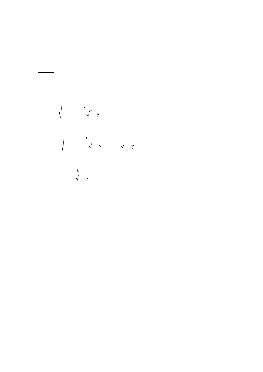
Final draft
3DJH
7 May 2003
SU(1
(8)
For the calculation of the resistance T
Rd
of closed hollow sections the design shear strength of the
individual parts of the cross section according to EN 1993-1-5 should be taken into account.
(9)
For combined shear force and torsional moment the plastic shear resistance accounting for torsional
effects should be reduced from V
pl,Rd
to V
pl,T,Rd
and the design shear force should satisfy:
1
V
V
Rd
,
T
,
pl
Ed
≤
(6.25)
in which V
pl,TEd,Rd
may be derived as follows:
–
for an I or H section:
( )
Rd
,
pl
0
M
y
t,Ed
Rd
,
T
,
pl
V
/
3
/
f
25
,
1
1
V
−
=
(6.26)
–
for a channel section:
(
)
(
)
Rd
,
pl
0
M
y
Ed
,
w
0
M
y
t,Ed
Rd
,
T
,
pl
V
/
3
/
f
/
3
/
f
25
,
1
1
V
τ
−
−
=
(6.27)
–
for a structural hollow section:
(
)
Rd
,
pl
0
M
y
t,Ed
Rd
,
T
,
pl
V
/
3
/
f
1
V
−
=
(6.28)
where V
pl,Rd
is given in 6.2.6.
%HQGLQJDQGVKHDU
(1)
Where the shear force is present allowance shall be made for its effect on the moment resistance.
(2)
Where the shear force is less than half the plastic shear resistance its effect on the moment resistance
may be neglected except where shear buckling reduces the section resistance, see EN 1993-1-5.
(3)
Otherwise the reduced moment resistance should be taken as the design resistance of the cross-section,
calculated using a reduced strength
(1 –
ρ) f
y
(6.29)
for the shear area,
where
2
Rd
,
pl
Ed
1
V
V
2
−
=
ρ
and V
pl,Rd
is obtained from 6.2.6(2).
127( See also 6.2.10(3).
(4)
When torsion is present
ρ should be obtained from
2
Rd
,
T
,
pl
Ed
1
V
V
2
−
=
ρ
, see 6.2.7, but should be taken
as 1 for V
Ed
≤ 0,5V
pl,T,Rd
.

3DJH
Final draft
SU(1
7 May 2003
(5)
The reduced design plastic resistance moment allowing for the shear force may alternatively be
obtained for I-cross-sections with equal flanges and bending about the major axis as follows:
0
M
y
w
2
w
y
,
pl
Rd
,
V
,
y
f
t
4
A
W
M
γ
ρ
−
=
but
Rd
,
c
,
y
Rd
,
V
,
y
M
M
≤
(6.30)
where M
y,c,Rd
is obtained from 6.2.5(2)
and
A
w
= h
w
t
w
(6)
For the interaction of bending, shear and transverse loads see section 7 of EN 1993-1-5.
%HQGLQJDQGD[LDOIRUFH
&ODVVDQGFURVVVHFWLRQV
(1)
Where an axial force is present, allowance shall be made for its effect on the plastic moment
resistance.
(2)
For class 1 and 2 cross sections, the following criterion should be satisfied:
M
Ed
≤ M
N,Rd
(6.31)
where M
N,Rd
is the design plastic moment resistance reduced due to the axial force N
Ed
.
(3)
For a rectangular solid section without bolt holes M
N,Rd
should be taken as:
(
)
[
]
2
Rd
,
pl
Ed
Rd
,
pl
Rd
,
N
N
/
N
1
M
M
−
=
(6.32)
(4)
For doubly symmetrical I- and H-sections or other flanges sections, allowance need not be made for
the effect of the axial force on the plastic resistance moment about the y-y axis when both the following
criteria are satisfied:
Rd
,
pl
Ed
N
0,25
N
≤
and
(6.33)
0
M
y
w
w
Ed
f
t
h
0,5
N
γ
≤
(6.34)
For doubly symmetrical I- and H-sections, allowance need not be made for the effect of the axial force on the
plastic resistance moment about the z-z axis when:
0
M
y
w
w
Ed
f
t
h
N
γ
≤
(6.35)
(5)
For cross-sections where bolt holes are not to be accounted for, the following approximations may be
used for standard rolled I or H sections and for welded I or H sections with equal flanges:
M
N,y,Rd
= M
pl,y,Rd
(1-n)/(1-0,5a) but M
N,y,Rd
≤ M
pl,y,Rd
(6.36)
for n
≤ a: M
N,z,Rd
= M
pl,z,Rd
(6.37)
for n > a: M
N,z,Rd
= M
pl,z,Rd
−
−
−
2
a
1
a
n
1
(6.38)
where n = N
Ed
/ N
pl.Rd
a = (A-2bt
f
)/A but a
≤ 0,5

Final draft
3DJH
7 May 2003
SU(1
For cross-sections where bolt holes are not to be accounted for, the following approximations may be used
for rectangular structural hollow sections of uniform thickness and for welded box sections with equal
flanges and equal webs:
M
N,y,Rd
= M
pl,y,Rd
(1 - n)/(1 - 0,5a
w
) but M
N,y,Rd
≤ M
pl,y.Rd
(6.39)
M
N,z,Rd
= M
pl,z,Rd
(1 - n)/(1 - 0,5a
f
) but M
N,z,Rd
≤ M
pl,z,Rd
(6.40)
where a
w
= (A - 2bt)/A but a
w
≤ 0,5 for hollow sections
a
w
= (A-2bt
f
)/A
but a
w
≤ 0,5 for welded box sections
a
f
= (A - 2ht)/A but a
f
≤ 0,5 for hollow sections
a
f
= (A-2ht
w
)/A but a
f
≤ 0,5 for welded box sections
(6)
For bi-axial bending the following criterion may be used:
1
M
M
M
M
Rd
,
z
,
N
Ed
,
z
Rd
,
y
,
N
Ed
,
y
≤
+
β
α
(6.41)
in which
α and β are constants, which may conservatively be taken as unity, otherwise as follows:
–
I and H sections:
1
but
n
5
;
2
≥
β
=
β
=
α
–
circular hollow sections:
2
;
2
=
β
=
α
–
rectangular hollow sections:
2
n
13
,
1
1
66
,
1
−
=
β
=
α
6
but
≤
β
=
α
where
n = N
Ed
/ N
pl,Rd
.
&ODVVFURVVVHFWLRQV
(1)
In the absence of shear force, for Class 3 cross-sections the maximum longitudinal stress shall satisfy
the criterion:
0
M
y
Ed
,
x
f
γ
≤
σ
(6.42)
where
Ed
,
x
σ
is the design value of the local longitudinal stress due to moment and axial force taking account
of bolt holes where relevant, see 6.2.4 and 6.2.5
&ODVVFURVVVHFWLRQV
(1)
In the absence of shear force, for Class 4 cross-sections the maximum longitudinal stress
σ
x,Ed
calculated using the effective cross sections (see 5.5.2(2)) shall satisfy the criterion:
0
M
y
Ed
,
x
f
γ
≤
σ
(6.43)
where
Ed
,
x
σ
is the design value of the local longitudinal stress due to moment and axial force taking account
of bolt holes where relevant, see 6.2.4 and 6.2.5

3DJH
Final draft
SU(1
7 May 2003
(2)
The following criterion should be met:
1
/
f
W
e
N
M
/
f
W
e
N
M
/
f
A
N
0
M
y
min
,
z
,
eff
Nz
Ed
Ed
,
z
0
M
y
min
,
y
,
eff
Ny
Ed
Ed
,
y
0
M
y
eff
Ed
≤
γ
+
+
γ
+
+
γ
(6.44)
where A
eff
is the effective area of the cross-section when subjected to uniform compression
W
eff,min
is the effective section modulus (corresponding to the fibre with the maximum elastic stress)
of the cross-section when subjected only to moment about the relevant axis
e
N
is the shift of the relevant centroidal axis when the cross-section is subjected to compression
only, see 6.2.2.5(4)
127( The signs of N
Ed
, M
y,Ed
, M
z,Ed
and
∆M
i
= N
Ed
e
Ni
depend on the combination of the respective
direct stresses.
%HQGLQJVKHDUDQGD[LDOIRUFH
(1)
Where shear and axial force are present, allowance shall be made for the effect of both shear force and
axial force on the resistance moment.
(2)
Provided that the design value of the shear force V
Ed
does not exceed 50% of the design plastic shear
resistance V
pl.Rd
no reduction of the resistances defined for bending and axial force in 6.2.9 need be made,
except where shear buckling reduces the section resistance, see EN 1993-1-5.
(3)
Where V
Ed
exceeds 50% of V
pl.Rd
the design resistance of the cross-section to combinations of moment
and axial force should be calculated using a reduced yield strength
(1-
ρ)f
y
(6.45)
for the shear area
where
ρ= (2V
Ed
/ V
pl.Rd
-1)
2
and V
pl,Rd
is obtained from 6.2.6(2).
127( Instead of reducing the yield strength also the plate thickness of the relevant part of the cross
section may be reduced.
%XFNOLQJUHVLVWDQFHRIPHPEHUV
8QLIRUPPHPEHUVLQFRPSUHVVLRQ
%XFNOLQJUHVLVWDQFH
(1)
A compression member shall be verified against buckling as follows:
0
,
1
N
N
Rd
,
b
Ed
≤
(6.46)
where N
Ed
is the design value of the compression force
N
b,Rd
is the design buckling resistance of the compression member.
(2)
For members with non-symmetric Class 4 sections allowance should be made for the additional
moment
∆M
Ed
due to the eccentricity of the centroidal axis of the effective section, see also 6.2.2.5(4), abd
the interaction should be carried out to 6.3.4 or 6.3.3.
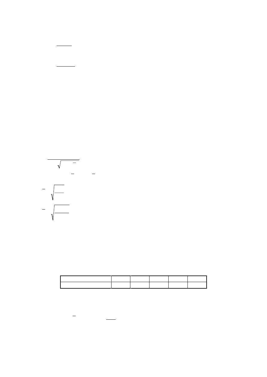
Final draft
3DJH
7 May 2003
SU(1
(3)
The design buckling resistance of a compression member should be taken as:
1
M
y
Rd
,
b
f
A
N
γ
χ
=
for Class 1, 2 and 3 cross-sections
(6.47)
1
M
y
eff
Rd
,
b
f
A
N
γ
χ
=
for Class 4 cross-sections
(6.48)
where
χ is the reduction factor for the relevant buckling mode.
127(For determining the buckling resistance of members with tapered sections along the member
or for non-uniform distribution of the compression force second order analysis according to 5.3.4(2)
may be performed. For out-of-plane buckling see also 6.3.4.
(4)
In determining A and A
eff
holes for fasteners at the column ends need not to be taken into account.
%XFNOLQJFXUYHV
(1)
For axial compression in members the value of
χ for the appropriate non-dimensional slendernessλ
should be determined from the relevant buckling curve according to:
2
2
1
λ
−
Φ
+
Φ
=
χ
but
0
,
1
≤
χ
(6.49)
where
(
)
[
]
2
2
,
0
1
5
,
0
λ
+
−
λ
α
+
=
Φ
cr
y
N
Af
=
λ
for Class 1, 2 and 3 cross-sections
cr
y
eff
N
f
A
=
λ
for Class 4 cross-sections
α
is an imperfection factor
N
cr
is the elastic critical force for the relevant buckling mode based on the gross cross sectional
properties.
(2)
The imperfection factor
α corresponding to the appropriate buckling curve should be obtained from
Table 6.1 and Table 6.2.
7DEOH,PSHUIHFWLRQIDFWRUVIRUEXFNOLQJFXUYHV
Buckling curve
a
0
a
b
c
d
Imperfection factor
α
0,13
0,21
0,34
0,49
0,76
(3)
Values of the reduction factor
χ for the appropriate non-dimensional slendernessλ may be obtained
from Figure 6.4.
(4)
For slenderness
2
,
0
≤
λ
or for
04
,
0
N
N
cr
Ed
≤
the buckling effects may be ignored and only cross
sectional checks apply.
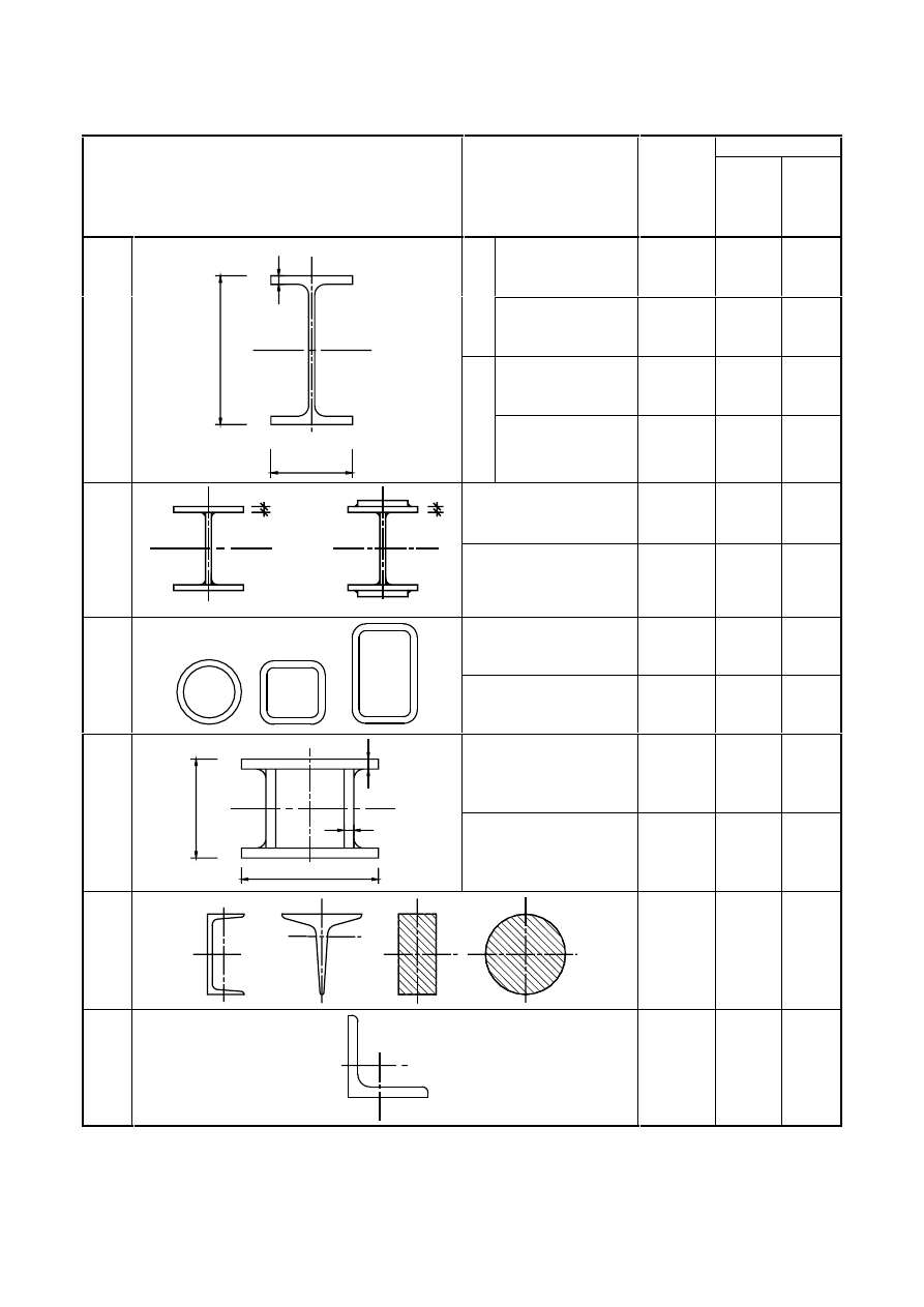
3DJH
Final draft
SU(1
7 May 2003
7DEOH6HOHFWLRQRIEXFNOLQJFXUYHIRUDFURVVVHFWLRQ
Buckling curve
Cross section
Limits
Buckling
about
axis
S 235
S 275
S 355
S 420
S 460
t
f
≤ 40 mm
y – y
z – z
a
b
a
0
a
0
h/b > 1
,2
40 mm < t
f
≤ 100
y – y
z – z
b
c
a
a
t
f
≤ 100 mm
y – y
z – z
b
c
a
a
Rolle
d se
ct
ions
b
h
y
y
z
z
t
f
h/b
≤
1,2
t
f
> 100 mm
y – y
z – z
d
d
c
c
t
f
≤ 40 mm
y – y
z – z
b
c
b
c
Weld
ed
I-s
ect
ion
s
t
t
f
f
y
y
y
y
z
z
t
f
> 40 mm
y – y
z – z
c
d
c
d
hot finished
any
a
a
0
H
o
llow
sect
ion
s
cold formed
any
c
c
generally (except as
below)
any
b
b
Weld
ed bo
x
sect
ion
s
t
t
f
b
h
y
y
z
z
w
thick welds: a > 0,5t
f
b/t
f
< 30
h/t
w
<30
any
c
c
U-, T- an
d
sol
id se
ct
ions
any
c
c
L-sec
ti
ons
any
b
b
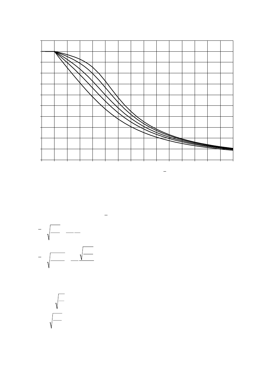
Final draft
3DJH
7 May 2003
SU(1
Reduct
ion fac
to
r
χ
0,0
0,1
0,2
0,3
0,4
0,5
0,6
0,7
0,8
0,9
1,0
1,1
0,0
0,2
0,4
0,6
0,8
1,0
1,2
1,4
1,6
1,8
2,0
2,2
2,4
2,6
2,8
3,0
a
0
b
c
d
a
Non-dimensional slenderness
λ
)LJXUH%XFNOLQJFXUYHV
6OHQGHUQHVVIRUIOH[XUDOEXFNOLQJ
(1)
The non-dimensional slenderness
λ
is given by:
1
cr
cr
y
1
i
L
N
Af
λ
=
=
λ
for Class 1, 2 and 3 cross-sections
(6.50)
1
eff
cr
cr
y
eff
A
A
i
L
N
f
A
λ
=
=
λ
for Class 4 cross-sections
(6.51)
where L
cr
is the buckling length in the buckling plane considered
i
is the radius of gyration about the relevant axis, determined using the properties of the gross
cross-section
ε
=
π
=
λ
9
,
93
f
E
y
1
y
f
235
=
ε
(f
y
in N/mm
2
)
127(% For elastic buckling of components of building structures see Annex BB.
(2)
For flexural buckling the appropriate buckling curve should be determined from Table 6.2.
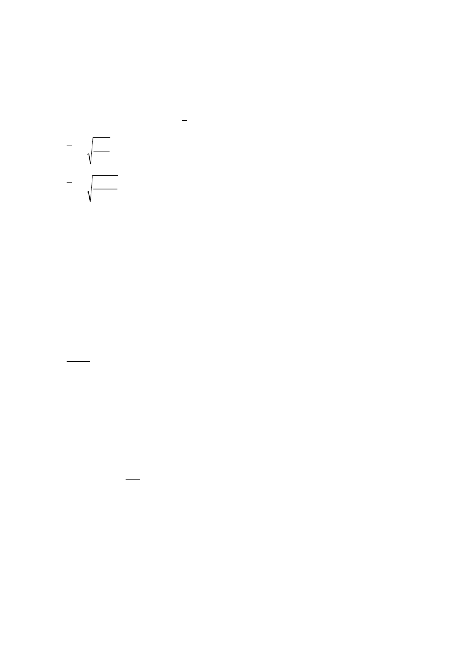
3DJH
Final draft
SU(1
7 May 2003
6OHQGHUQHVVIRUWRUVLRQDODQGWRUVLRQDOIOH[XUDOEXFNOLQJ
(1)
For members with open cross-sections account should be taken of the possibility that the resistance of
the member to either torsional or torsional-flexural buckling could be less than its resistance to flexural
buckling.
(2)
The non-dimensional slenderness
T
λ
for torsional or torsional-flexural buckling should be taken as:
cr
y
T
N
Af
=
λ
for Class 1, 2 and 3 cross-sections
(6.52)
cr
y
eff
T
N
f
A
=
λ
for Class 4 cross-sections
(6.53)
where
T
cr,
cr
TF
,
cr
cr
N
N
but
N
N
<
=
N
cr,TF
is the elastic torsional-flexural buckling force
N
cr,T
is the elastic torsional buckling force
(3)
For torsional or torsional-flexural buckling the appropriate buckling curve may be determined from
Table 6.2 considering the one related to the z-axis.
8QLIRUPPHPEHUVLQEHQGLQJ
%XFNOLQJUHVLVWDQFH
(1)
A laterally unrestrained beam subject to major axis bending shall be verified against lateral-torsional
buckling as follows:
0
,
1
M
M
Rd
,
b
Ed
≤
(6.54)
where M
Ed
is the design value of the moment
M
b,Rd
is the design buckling resistance moment.
(2)
Beams with sufficient restraint to the compression flange are not susceptible to lateral-torsional
buckling. In addition, beams with certain types of cross-sections, such as square or circular hollow sections,
fabricated circular tubes or square box sections are not susceptible to lateral-torsional buckling.
(3)
The design buckling resistance moment of a laterally unrestrained beam should be taken as:
1
M
y
y
LT
Rd
,
b
f
W
M
γ
χ
=
(6.55)
where W
y
is the appropriate section modulus as follows:
–
W
y
= W
pl,y
for Class 1 or 2 cross-sections
–
W
y
= W
el,y
for Class 3 cross-sections
–
W
y
= W
eff,y
for Class 4 cross-sections
χ
LT
is the reduction factor for lateral-torsional buckling.
127( For determining the buckling resistance of beams with tapered sections second order
analysis according to 5.3.4(3) may be performed. For out-of-plane buckling see also 6.3.4.
127(% For buckling of components of building structures see also Annex BB.
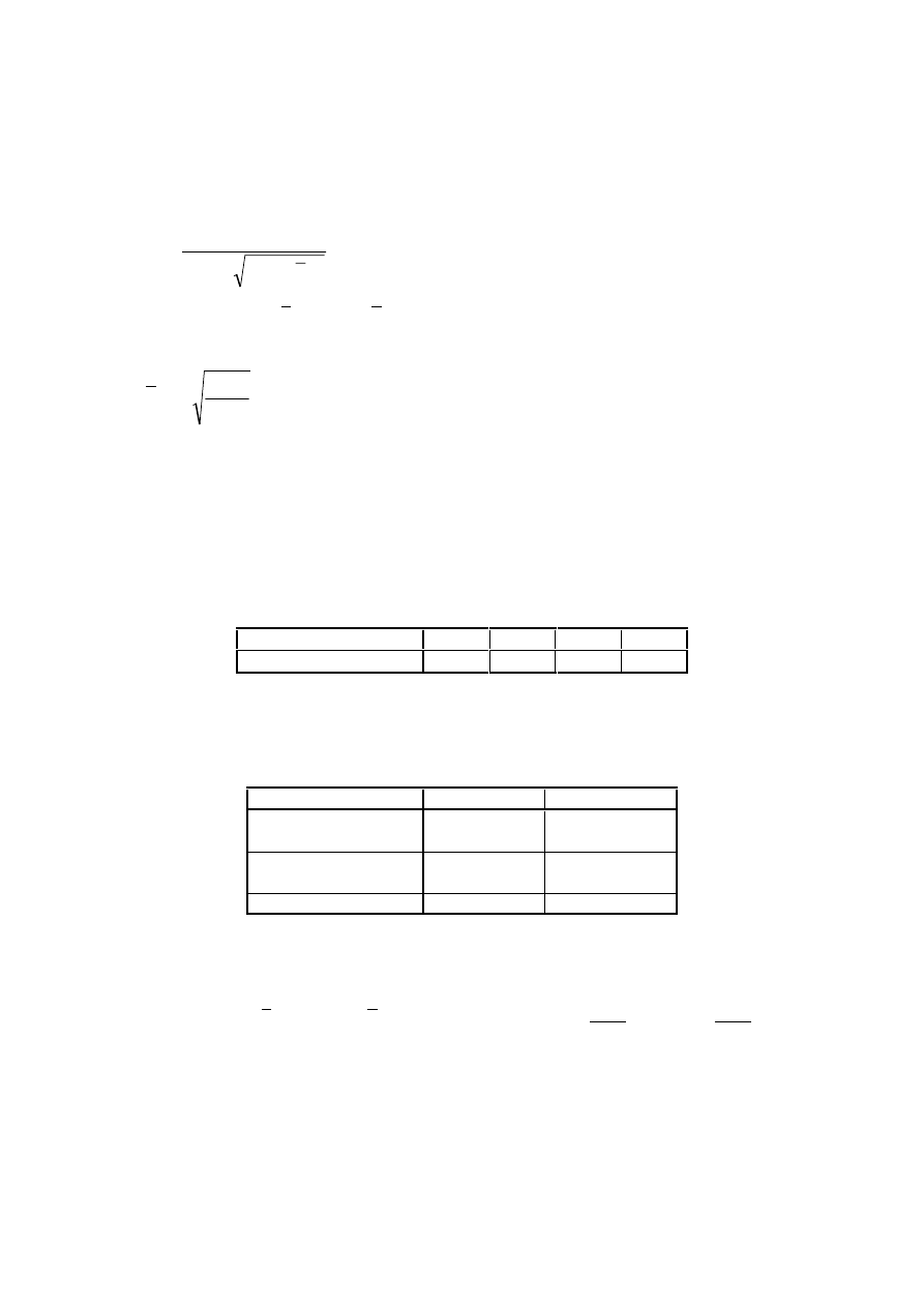
Final draft
3DJH
7 May 2003
SU(1
(4)
In determining W
y
holes for fasteners at the beam end need not to be taken into account.
/DWHUDOWRUVLRQDOEXFNOLQJFXUYHV±*HQHUDOFDVH
(1)
Unless otherwise specified, see 6.3.2.3, for bending members of constant cross-section, the value of
χ
LT
for the appropriate non-dimensional slenderness
λ
LT
, should be determined from:
0
,
1
but
1
LT
2
LT
2
LT
LT
LT
≤
χ
λ
−
Φ
+
Φ
=
χ
(6.56)
where
(
)
[
]
2
LT
LT
LT
LT
2
,
0
1
5
,
0
λ
+
−
λ
α
+
=
Φ
α
LT
is an imperfection factor
cr
y
y
LT
M
f
W
=
λ
M
cr
is the elastic critical moment for lateral-torsional buckling
(2)
M
cr
is based on gross cross sectional properties and takes into account the loading conditions, the real
moment distribution and the lateral restraints.
127( The imperfection factor α
LT
corresponding to the appropriate buckling curve may be obtained
from the National Annex. The recommended values
α
LT
are given in Table 6.3.
7DEOH,PSHUIHFWLRQIDFWRUVIRUODWHUDOWRUVLRQDOEXFNOLQJFXUYHV
Buckling curve
a
b
c
d
Imperfection factor
α
LT
0,21
0,34
0,49
0,76
The recommendations for buckling curves are given in Table 6.4.
7DEOH/DWHUDOWRUVLRQDOEXFNOLQJFXUYHIRUFURVVVHFWLRQVXVLQJHTXDWLRQ
Cross-section
Limits
Buckling curve
Rolled I-sections
h/b
≤ 2
h/b > 2
D
E
Welded I-sections
h/b
≤ 2
h/b > 2
F
G
Other cross-sections
-
G
(3)
Values of the reduction factor
χ
LT
for the appropriate non-dimensional slenderness
λ
LT
may be
obtained from Figure 6.4.
(4)
For slendernesses
2
,
0
LT
≤
λ
(or
4
,
0
LT
≤
λ
(see 6.3.2.3)) or for
04
,
0
M
M
cr
Ed
≤
(or
16
,
0
M
M
cr
Ed
≤
(see
6.3.2.3)) lateral torsional buckling effects may be ignored and only cross sectional checks apply.
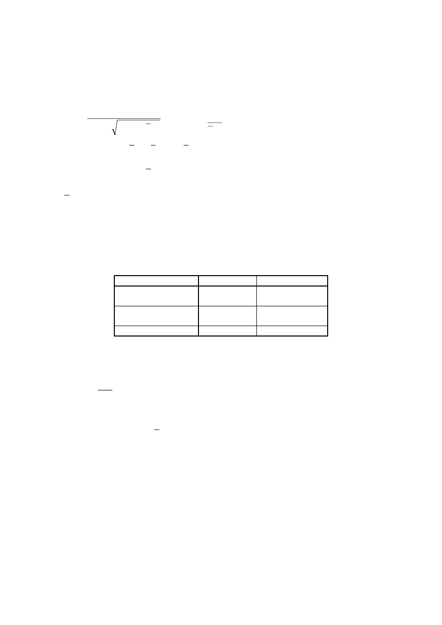
3DJH
Final draft
SU(1
7 May 2003
/DWHUDOWRUVLRQDOEXFNOLQJFXUYHVIRUUROOHGVHFWLRQVRUHTXLYDOHQWZHOGHGVHFWLRQV
(1)
For rolled or equivalent welded sections in bending the values of
χ
LT
for the appropriate non-
dimensional slenderness may be determined from
1
0
,
1
but
1
2
LT
LT
LT
2
LT
2
LT
LT
LT
λ
≤
χ
≤
χ
λ
β
−
Φ
+
Φ
=
χ
(6.57)
(
)
[
]
2
LT
0
,
LT
LT
LT
LT
1
5
,
0
λ
β
+
λ
−
λ
α
+
=
Φ
127( The parameters
0
,
LT
λ
and
β and any limitation of validity concerning the beam depth or h/b
ratio may be given in the National Annex. The following values are recommended for rolled sections:
4
,
0
0
,
LT
=
λ
(maximum value)
β = 0,75
(minimum value)
The recommendations for buckling curves are given in Table 6.5.
7DEOH6HOHFWLRQRIODWHUDOWRUVLRQDOEXFNOLQJFXUYHIRUFURVVVHFWLRQVXVLQJ
HTXDWLRQ
Cross-section
Limits
Buckling curve
Rolled I-sections
h/b
≤ 2
h/b > 2
E
F
Welded I-sections
h/b
≤ 2
h/b > 2
F
G
Other cross-sections
-
G
(2)
For taking into account the moment distribution between the lateral restraints of members the
reduction factor
χ
LT
may be modified as follows:
f
LT
mod
,
LT
χ
=
χ
but
1
mod
,
LT
≤
χ
(6.58)
127( The values f may be defined in the National Annex. The following minimum values are
recommended:
1,0
f
but
]
)
8
,
0
(
0
,
2
1
)[
k
1
(
5
,
0
1
f
2
LT
c
≤
−
λ
−
−
−
=
k
c
is a correction factor according to Table 6.6
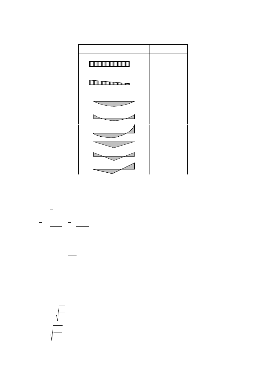
Final draft
3DJH
7 May 2003
SU(1
7DEOH&RUUHFWLRQIDFWRUVN
F
Moment distribution
k
c
ψ = 1
1,0
-1
≤ ψ ≤ 1
ψ
− 33
,
0
33
,
1
1
0,94
0,90
0,91
0,86
0,77
0,82
6LPSOLILHGDVVHVVPHQWPHWKRGVIRUEHDPVZLWKUHVWUDLQWVLQEXLOGLQJV
(1)B Members with discrete lateral restraint to the compression flange are not susceptible to lateral-
torsional buckling if the length L
c
between restraints or the resulting equivalent compression flange
slenderness
f
λ
satisfies:
Ed
,
y
Rd
,
c
0
c
1
z
,
f
c
c
f
M
M
i
L
k
λ
≤
λ
=
λ
(6.59)
where M
y,Ed
is the maximum design value of the bending moment within the restraint spacing
1
M
y
y
Rd
,
c
f
W
M
γ
=
W
y
is the appropriate section modulus of the compression flange
k
c
is a slenderness correction factor for moment distribution between restraints, see Table 6.6
i
f,z
is the radius of gyration of the compression flange including 1/3 of the compressed part of the
web area, about the minor axis of the section
0
c
λ
is the slenderness parameter of the above compression element
ε
=
π
=
λ
9
,
93
f
E
y
1
y
f
235
=
ε
(f
y
in N/mm
2
)
3DJH
Final draft
SU(1
7 May 2003
127(%For Class 4 cross-sections i
f,z
may be taken as
c
,
w
,
eff
f
,
eff
f
,
eff
z
,
f
A
3
1
A
I
i
+
=
where I
eff,f
is the effective second moment of area of the compression flange about the minor axis
of the section
A
eff,f
is the effective area of the compression flange
A
eff,w,c
is the effective areas of the compressed part of the web
127( % The slenderness limit
0
c
λ
may be given in the National Annex. A limit value
1
,
0
0
,
LT
0
c
+
λ
=
λ
is recommended, see 6.3.2.3.
(2)B If the slenderness of the compression flange
f
λ
exceeds the limit given in (1)B, the design buckling
resistance moment may be taken as:
Rd
,
c
f
Rd
,
b
M
k
M
χ
=
l
but
Rd
.
c
Rd
.
b
M
M
≤
(6.60)
where
χ
is the reduction factor of the equivalent compression flange determined with
f
λ
l
f
k
is the modification factor accounting for the conservatism of the equivalent compression flange
method
127( % The modification factor may be given in the National Annex. A value
10
,
1
k
f
=
l
is
recommended.
(3)B The buckling curves to be used in (2)B should be taken as follows:
curve d for welded sections provided that:
ε
≤ 44
t
h
f
curve c for all other sections
where h is the overall depth of the cross-section
t
is the thickness of the compression flange
127(% For lateral torsional buckling of components of building structures with restraints see also
Annex BB.3.
8QLIRUPPHPEHUVLQEHQGLQJDQGD[LDOFRPSUHVVLRQ
(1)
Unless second order analysis is carried out using the imperfections as given in 5.3.2, the stability of
uniform members with double symmetric cross sections for sections not susceptible to distortional
deformations should be checked as given in the following clauses, where a distinction is made for:
–
members that are not susceptible to torsional deformations, e.g. circular hollow sections or sections
restraint from torsion
–
members that are susceptible to torsional deformations, e.g. members with open cross-sections and not
restraint from torsion.
(2)
In addition, the resistance of the cross-sections at each end of the member should satisfy the
requirements given in 6.2.
127( The interaction formulae are based on the modelling of simply supported single span
members with end fork conditions and with or without continuous lateral restraints, which are
subjected to compression forces, end moments and/or transverse loads.
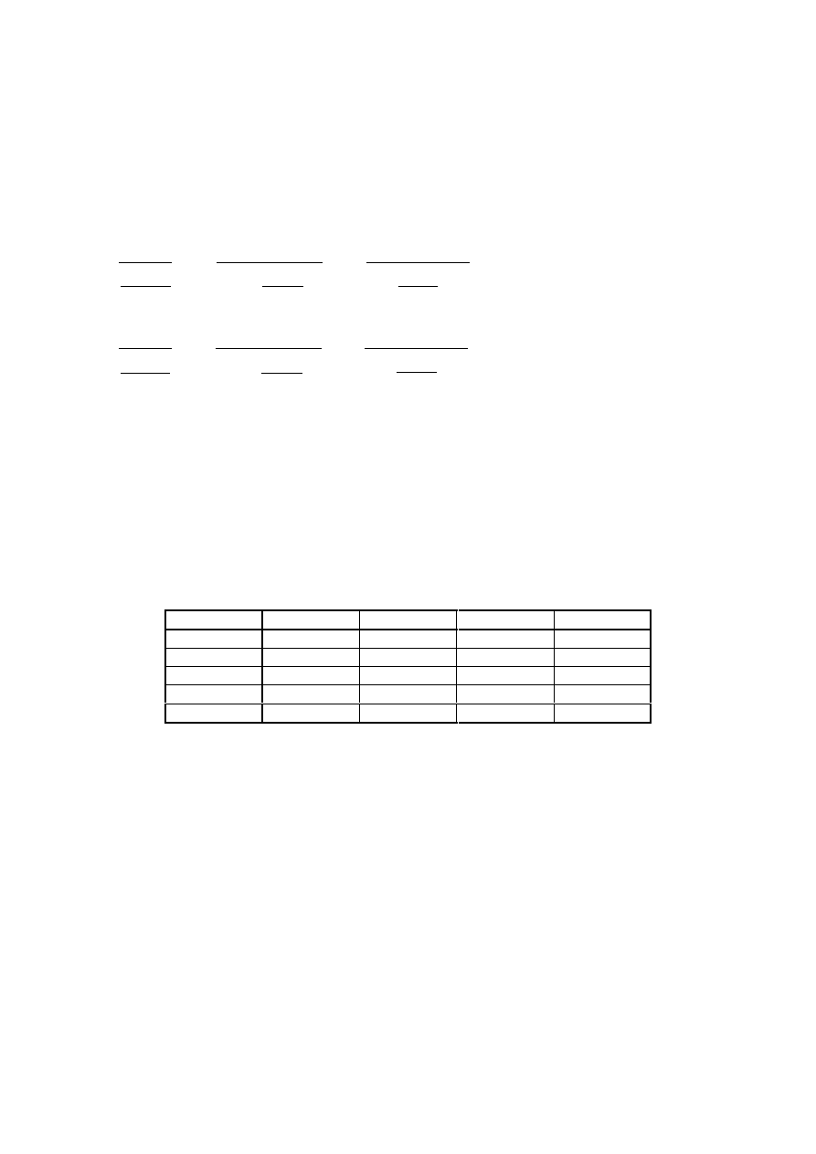
Final draft
3DJH
7 May 2003
SU(1
127( In case the conditions of application expressed in (1) and (2) are not fulfilled, see 6.3.4.
(3)
For members of structural systems the resistance check may be carried out on the basis of the
individual single span members regarded as cut out of the system. Second order effects of the sway system
(P-
∆-effects) have to be taken into account, either by the end moments of the member or by means of
appropriate buckling lengths respectively.
(4)
Members which are subjected to combined bending and axial compression should satisfy:
1
M
M
M
k
M
M
M
k
N
N
1
M
Rk
,
z
Ed
,
z
Ed
,
z
yz
1
M
Rk
,
y
LT
Ed
,
y
Ed
,
y
yy
1
M
Rk
y
Ed
≤
γ
∆
+
+
γ
χ
∆
+
+
γ
χ
(6.61)
1
M
M
M
k
M
M
M
k
N
N
1
M
Rk
,
z
Ed
,
z
Ed
,
z
zz
1
M
Rk
,
y
LT
Ed
,
y
Ed
,
y
zy
1
M
Rk
z
Ed
≤
γ
∆
+
+
γ
χ
∆
+
+
γ
χ
(6.62)
where N
Ed
, M
y,Ed
and M
z,Ed
are the design values of the compression force and the maximum moments
about the y-y and z-z axis along the member, respectively
∆M
y,Ed
,
∆M
z,Ed
are the moments due to the shift of the centroidal axis according to 6.2.9.3 for
class 4 sections, see Table 6.7,
χ
y
and
χ
z
are the reduction factors due to flexural buckling from 6.3.1
χ
LT
is the reduction factor due to lateral torsional buckling from 6.3.2
k
yy
, k
yz
, k
zy
, k
zz
are the interaction factors
7DEOH9DOXHVIRU1
5N
I
\
$
L
0
L5N
I
\
:
L
DQG∆0
L(G
Class
1
2
3
4
A
i
A
A
A
A
eff
W
y
W
pl,y
W
pl,y
W
el,y
W
eff,y
W
z
W
pl,z
W
pl,z
W
el,z
W
eff,z
∆M
y,Ed
0
0
0
e
N,y
N
Ed
∆M
z,Ed
0
0
0
e
N,z
N
Ed
127( For members not susceptible to torsional deformation χ
LT
would be
χ
LT
= 1,0.
(5)
The interaction factors k
yy
, k
yz
, k
zy
, k
zz
depend on the method which is chosen.
127( The interaction factors k
yy
, k
yz
, k
zy
and k
zz
have been derived from two alternative
approaches. Values of these factors may be obtained from Annex A (alternative method 1) or from
Annex B (alternative method 2).
127( The National Annex may give a choice from alternative method 1 or alternative method 2.
127( For simplicity verifications may be performed in the elastic range only.
*HQHUDOPHWKRGIRUODWHUDODQGODWHUDOWRUVLRQDOEXFNOLQJRIVWUXFWXUDOFRPSRQHQWV
(1)
The following method may be used where the methods given in 6.3.1, 6.3.2 and 6.3.3 do not apply. It
allows the verification of the resistance to lateral and lateral torsional buckling for structural components
such as
–
single members, built-up or not, uniform or not, with complex support conditions or not, or
–
plane frames or subframes composed of such members,
3DJH
Final draft
SU(1
7 May 2003
which are subject to compression and/or mono-axial bending in the plane, but which do not contain rotative
plastic hinges.
127( The National Annex may specify the field and limits of application of this method.
(2)
Overall resistance to out-of-plane buckling for any structural component conforming to the scope in
(1) can be verified by ensuring that:
0
,
1
1
M
k
,
ult
op
≥
γ
α
χ
(6.63)
where
α
ult,k
is the minimum load amplifier of the design loads to reach the characteristic resistance of the
most critical cross section of the structural component considering its in plane behaviour
without taking lateral or lateral torsional buckling into account however accounting for all
effects due to in plane geometrical deformation and imperfections, global and local, where
relevant
op
χ
is the reduction factor for the non-dimensional slenderness
op
λ
, see (3), to take account of
lateral and lateral torsional buckling
(3)
The global non dimensional slenderness
op
λ
for the structural component should be determined from
LT
,
cr
k
,
ult
op
α
α
=
λ
(6.64)
where
α
ult,k
is defined in (2)
α
cr,op
is the minimum amplifier for the in plane design loads to reach the elastic critical resistance of
the structural component with regards to lateral or lateral torsional buckling without
accounting for in plane flexural buckling
127( In determining α
cr,op
and
α
ult,k
Finite Element analysis may be used.
(4)
The reduction factor
*
LT
χ
may be determined from either of the following methods:
a) the minimum value of
χ
for lateral buckling according to 6.3.1
χ
LT
for lateral torsional buckling according to 6.3.2
each calculated for the global non dimensional slenderness
op
λ
127( For example where α
ult,k
is determined by the cross section check
Rk
,
y
Ed
,
y
Rk
Ed
k
,
ult
M
M
N
N
1
+
=
α
this
method leads to:
op
1
M
Rk
,
y
Ed
,
y
1
M
Rk
Ed
M
M
N
N
χ
≤
γ
+
γ
(6.65)
b) a value interpolated between the values
χ and χ
LT
as determined in a) by using the formula for
α
ult,k
corresponding to the critical cross section
127( For example where α
ult,k
is determined by the cross section check
Rk
,
y
Ed
,
y
Rk
Ed
k
,
ult
M
M
N
N
1
+
=
α
this
method leads to:
Final draft
3DJH
7 May 2003
SU(1
1
M
M
N
N
1
M
Rk
,
y
LT
Ed
,
y
1
M
Rk
Ed
≤
γ
χ
+
γ
χ
(6.66)
/DWHUDOWRUVLRQDOEXFNOLQJRIPHPEHUVZLWKSODVWLFKLQJHV
*HQHUDO
(1)B Structures may be designed with plastic analysis provided lateral torsional buckling in the frame is
prevented by the following means:
a) restraints at locations of “rotated” plastic hinges, see 6.3.5.2, and
b) verification of stable length of segment between such restraints and other lateral restraints, see 6.3.5.3
(2)B Where under all ultimate limit state load combinations, the plastic hinge is “not-rotated” no restraints
are necessary for such a plastic hinge.
5HVWUDLQWVDWURWDWHGSODVWLFKLQJHV
(1)B At each rotated plastic hinge location the cross section should have an effective lateral and torsional
restraint with appropriate resistance to lateral forces and torsion induced by local plastic deformations of the
member at this location.
(2)B Effective restraint should be provided
–
for members carrying either moment or moment and axial force by lateral restraint to both flanges. This
may be provided by lateral restraint to one flange and a stiff torsional restraint to the cross-section
preventing the lateral displacement of the compression flange relative to the tension flange, see Figure
6.5.
–
for members carrying either moment alone or moment and axial tension in which the compression flange
is in contact with a floor slab, by lateral and torsional restraint to the compression flange (e.g. by
connecting it to a slab, see Figure 6.6). For cross-sections that are more slender than rolled I and H
sections the distorsion of the cross section should be prevented at the plastic hinge location (e.g. by
means of a web stiffener also connected to the compression flange with a stiff connection from the
compression flange into the slab).
)LJXUH7\SLFDOVWLIIWRUVLRQDOUHVWUDLQW
1
FRPSUHVVLRQIODQJH
)LJXUH7\SLFDOODWHUDODQGWRUVLRQDOUHVWUDLQWE\DVODEWRWKHFRPSUHVVLRQ
IODQJH
3DJH
Final draft
SU(1
7 May 2003
(3)B At each plastic hinge location, the connection (e.g. bolts) of the compression flange to the resisting
element at that point (e.g. purlin), and any intermediate element (e.g. diagonal brace) should be designed to
resist a local force equal to 2,5% of N
f,Ed
(defined in 6.3.5.2(5)B) transmitted by the flange in its plane and
perpendicular to the web plane, without any combination with other loads.
(4)B Where it is not practicable providing such a restraint directly at the hinge location, it should be
provided within a distance of h/2 along the length of the member, where h is its overall depth at the plastic
hinge location.
(5)B For the design of bracing systems, see 5.3.3, it should be verified by a check in addition to the check
for imperfection according to 5.3.3 that the bracing system is able to resist the effects of local forces Q
m
applied at each stabilised member at the plastic hinge locations, where;
100
N
5
,
1
Q
Ed
,
f
m
m
α
=
(6.67)
where N
f,Ed
is the axial force in the compressed flange of the stabilised member at the plastic hinge
location
α
m
is according to 5.3.3(1)
127( For combination with external loads see also 5.3.3(5).
9HULILFDWLRQRIVWDEOHOHQJWKRIVHJPHQW
(1)B The lateral torsional buckling verification of segments between restraints may be performed by
checking that the length between restraints is not greater than the stable length.
For uniform beam segments with I or H cross sections with
ε
≤ 40
t
h
f
under linear moment and without
significant axial compression the stable length may be taken from
(
)
625
,
0
1
for
i
40
60
L
1
625
,
0
for
i
35
L
z
stable
z
stable
≤
ψ
≤
−
ε
ψ
−
=
≤
ψ
≤
ε
=
(6.68)
where
[
]
2
y
mm
/
N
f
235
=
ε
Rd
,
pl
min
,
Ed
M
M
=
ψ
= ratio of end moments in the segment
127(% For the stable length of a segment see also Annex BB.3.
(2)B Where a rotated plastic hinge location occurs immediately adjacent to one end of a haunch, the tapered
segment need not be treated as a segment adjacent to a plastic hinge location if the following criteria are
satisfied:
a) the restraint at the plastic hinge location should be within a distance h/2 along the length of the tapered
segment, not the uniform segment
b) the compression flange of the haunch remains elastic throughout its length
127(% For more information see Annex BB.3.
Final draft
3DJH
7 May 2003
SU(1
8QLIRUPEXLOWXSFRPSUHVVLRQPHPEHUV
*HQHUDO
(1)
Uniform built-up compression members with hinged ends that are laterally supported should be
designed with the following model, see Figure 6.7.
1. The member may be considered as a column with a bow imperfection
500
L
e
0
=
2. The elastic deformations of lacings or battenings, see Figure 6.7, may be considered by a continuous
(smeared) shear stiffness S
V
of the column.
127( For other end conditions appropriate modifications may be performed.
(2)
The model of a uniform built-up compression member applies when
1. the lacings or battenings consist of equal modules with parallel chords
2. the minimum numbers of modules in a member is three.
127( This assumption allows the structure to be regular and smearing the discrete structure to a
continuum.
(3)
The design procedure is applicable to built-up members with lacings in two directions, see
Figure 6.8.
(4)
The chords may be solid members or may themselves be laced or battened in the perpendicular plane.
e
0
= L/500
)LJXUH8QLIRUPEXLOWXSFROXPQVZLWKODFLQJVDQGEDWWHQLQJV
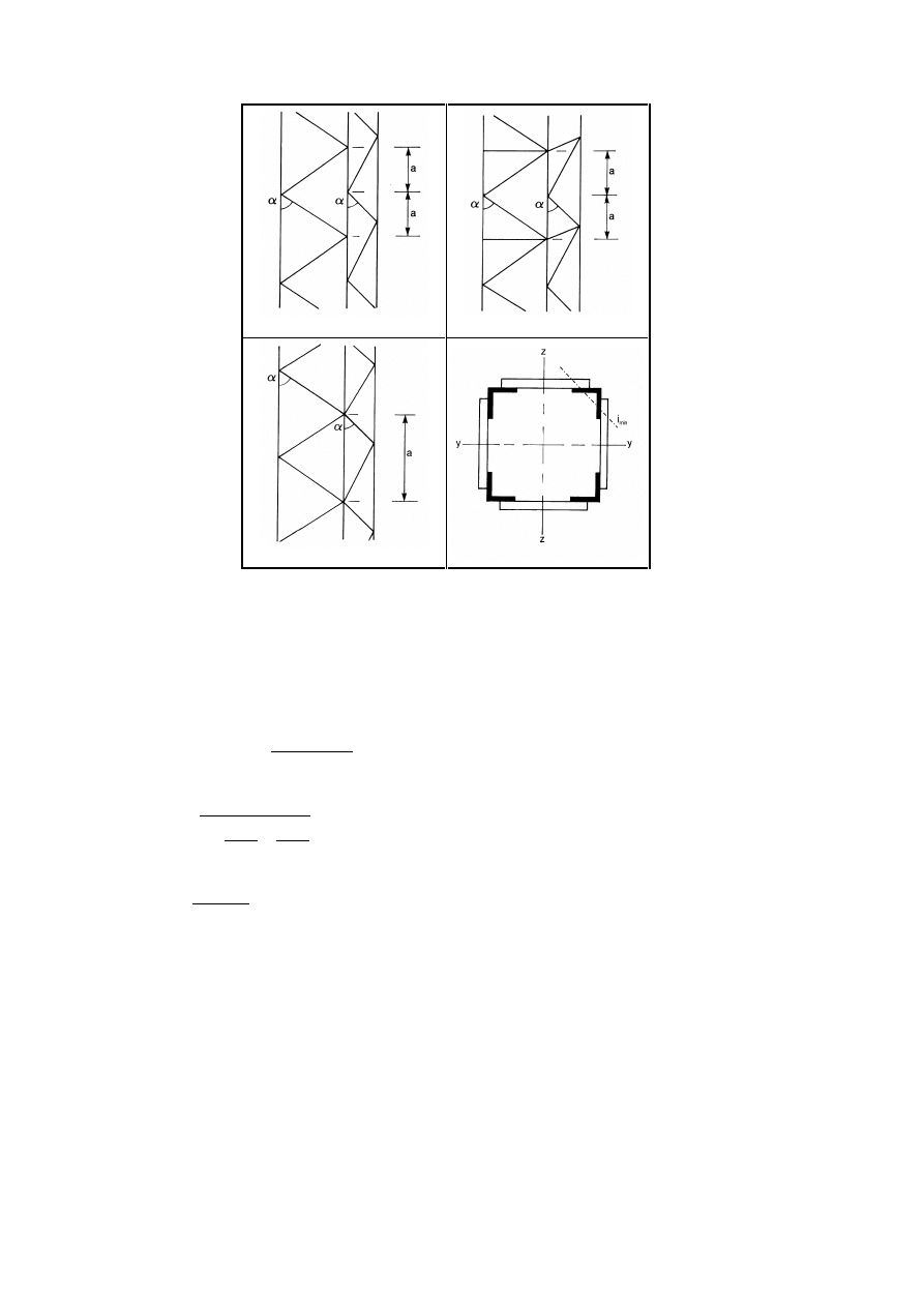
3DJH
Final draft
SU(1
7 May 2003
L
ch
= 1,52a
L
ch
= 1,28a
L
ch
= a
)LJXUH/DFLQJVRQIRXUVLGHVDQGEXFNOLQJOHQJWK/
FK
RIFKRUGV
(5)
Checks should be performed for chords using the design chord forces N
ch,Ed
from compression forces
N
Ed
and moments M
Ed
at mid span of the built-up member.
(6)
For a member with two identical chords the design force N
ch,Ed
should be determined from:
eff
ch
0
Ed
Ed
Ed
,
ch
I
2
A
h
M
N
5
,
0
N
+
=
(6.69)
where
v
Ed
cr
Ed
I
Ed
0
Ed
Ed
S
N
N
N
1
M
e
N
M
−
−
+
=
2
eff
2
cr
L
EI
N
π
=
is the effective critical force of the built-up member
N
Ed
is the design value of the compression force to the built-up member
M
Ed
is the design value of the maximum moment in the middle of the built-up member considering
second order effects
I
Ed
M
is the design value of the maximum moment in the middle of the built-up member without
second order effects
h
0
is the distance between the centroids of chords
A
ch
is the cross-sectional area of one chord
I
eff
is the effective second moment of area of the built-up member, see 6.4.2 and 6.4.3
S
v
is the shear stiffness of the lacings or battened panel, see 6.4.2 and 6.4.3.
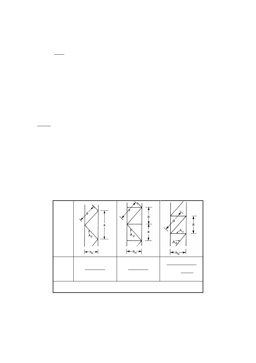
Final draft
3DJH
7 May 2003
SU(1
(7)
The checks for the lacings of laced built-up members or for the frame moments and shear forces of the
battened panels of battened built-up members should be performed for the end panel taking account of the
shear force in the built-up member:
L
M
V
Ed
Ed
π
=
(6.70)
/DFHGFRPSUHVVLRQPHPEHUV
5HVLVWDQFHRIFRPSRQHQWVRIODFHGFRPSUHVVLRQPHPEHUV
(1)
The chords and diagonal lacings subject to compression should be designed for buckling.
127( Secondary moments may be neglected.
(2)
For chords the buckling verification should be performed as follows:
0
,
1
N
N
Rd
,
b
Ed
,
ch
≤
(6.71)
where N
ch,Ed
is the design compression force in the chord at mid-length of the built-up member according to
6.4.1(6)
and
N
b,Rd
is the design value of the buckling resistance of the chord taking the buckling length L
ch
from
Figure 6.8.
(3)
The shear stiffness S
V
of the lacings should be taken from Figure 6.9.
(4)
The effective second order moment of area of laced built-up members may be taken as:
ch
2
0
eff
A
h
5
,
0
I
=
(6.72)
System
S
V
3
2
0
d
d
2
ah
nEA
3
2
0
d
d
ah
nEA
+
3
V
3
0
d
3
2
0
d
d
A
h
A
1
d
ah
nEA
n is the number of planes of lacings
A
d
and A
V
refer to the cross sectional area of the bracings
)LJXUH6KHDUVWLIIQHVVRIODFLQJVRIEXLOWXSPHPEHUV
&RQVWUXFWLRQDOGHWDLOV
(1)
Single lacing systems in opposite faces of the built-up member with two parallel laced planes should
be corresponding systems as shown in Figure 6.10(a), arranged so that one is the shadow of the other.
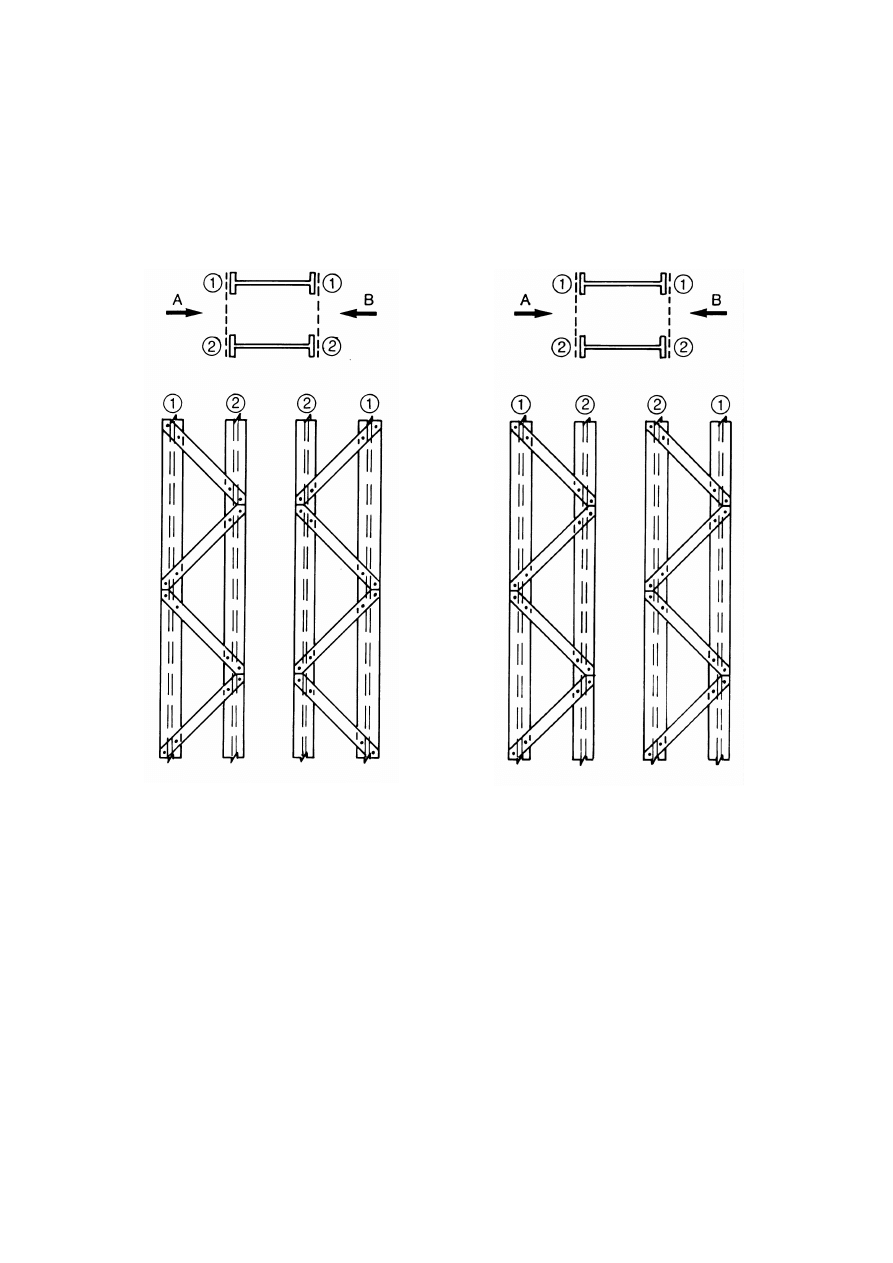
3DJH
Final draft
SU(1
7 May 2003
(2)
When the single lacing systems on opposite faces of a built-up member with two parallel laced planes
are mutually opposed in direction as shown in Figure 6.10(b), the resulting torsional effects in the member
should be taken into account.
(3)
Tie panels should be provided at the ends of lacing systems, at points where the lacing is interrupted
and at joints with other members.
chord
Ê
chord
Ê
Lacing on face A
Lacing on face B
Lacing on face A
Lacing on face B
a) Corresponding lacing system
(Recommended system)
b) Mutually opposed lacing system
(Not recommended)
)LJXUH6LQJOHODFLQJV\VWHPRQRSSRVLWHIDFHVRIDEXLOWXSPHPEHUZLWK
WZRSDUDOOHOODFHGSODQHV
%DWWHQHGFRPSUHVVLRQPHPEHUV
5HVLVWDQFHRIFRPSRQHQWVRIEDWWHQHGFRPSUHVVLRQPHPEHUV
(1)
The chords and the battens and their joints to the chords should be checked for the actual moments and
forces in an end panel and at mid-span as indicated in Figure 6.11.
127( For simplicity the maximum chord forces N
ch,Ed
may be combined with the maximum shear
force V
Ed
.
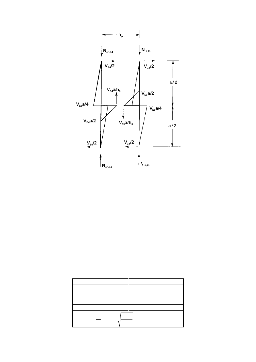
Final draft
3DJH
7 May 2003
SU(1
)LJXUH0RPHQWVDQGIRUFHVLQDQHQGSDQHORIDEDWWHQHGEXLOWXSPHPEHU
(2)
The shear stiffness S
V
should be taken as follows:
2
ch
2
0
b
ch
2
ch
v
a
EI
2
a
h
nI
I
2
1
a
EI
24
S
π
≤
+
=
(6.73)
(3)
The effective second moments of area of battened built-up members may be taken as:
ch
ch
2
0
eff
I
2
A
h
5
,
0
I
µ
+
=
(6.74)
where I
ch
= in plane second moment of area of one chord
I
b
= in plane second moment of area of one batten
µ = efficiency factor from Table 6.8
7DEOH(IILFLHQF\IDFWRUµ
criterion
efficiency factor
µ
λ ≥ 150
0
75 <
λ < 150
75
2
λ
−
=
µ
λ ≤ 75
1,0
where
0
i
L
=
λ
;
ch
1
0
A
2
I
i
=
;
ch
ch
2
0
1
I
2
A
h
5
,
0
I
+
=
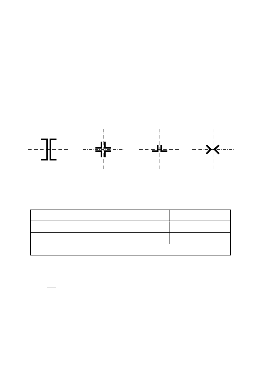
3DJH
Final draft
SU(1
7 May 2003
'HVLJQGHWDLOV
(1)
Battens should be provided at each end of a member.
(2)
Where parallel planes of battens are provided, the battens in each plane should be arranged opposite
each other.
(3)
Battens should also be provided at intermediate points where loads are applied or lateral restraint is
supplied.
&ORVHO\VSDFHGEXLOWXSPHPEHUV
(1)
Built-up compression members with chords in contact or closely spaced and connected through
packing plates, see Figure 6.12, or star battened angle members connected by pairs of battens in two
perpendicular planes, see Figure 6.13 should be checked for buckling as a single integral member ignoring
the effect of shear stiffness (S
V
=
∞), when the conditions in Table 6.9 are met.
y
y
z
z
y
y
z
z
y
y
z
z
y
y
z
z
)LJXUH&ORVHO\VSDFHGEXLOWXSPHPEHUV
7DEOH0D[LPXPVSDFLQJVIRULQWHUFRQQHFWLRQVLQFORVHO\VSDFHGEXLOWXSRU
VWDUEDWWHQHGDQJOHPHPEHUV
Type of built-up member
Maximum spacing between
interconnections *)
Members according to Figure 6.12 connected by bolts or welds
15 i
min
Members according to Figure 6.13 connected by pair of battens
70 i
min
*)
centre-to-centre distance of interconnections
i
min
is the minimum radius of gyration of one chord or one angle
(2)
The shear forces to be transmitted by the battens should be determined from 6.4.3.1(1).
(3)
In the case of unequal-leg angles, see Figure 6.13, buckling about the y-y axis may be verified with:
15
,
1
i
i
0
y
=
(6.75)
where i
0
is the minimum radius of gyration of the built-up member.
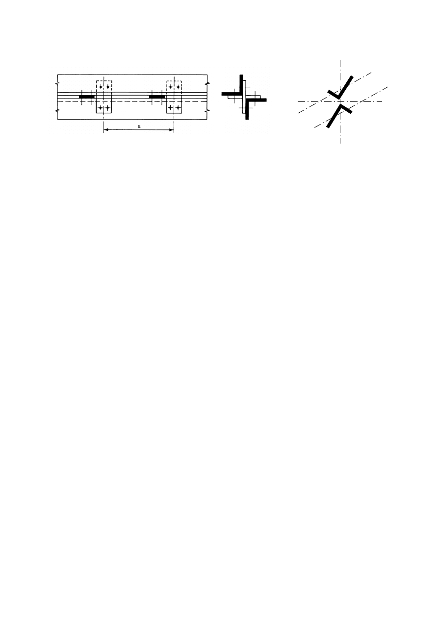
Final draft
3DJH
7 May 2003
SU(1
z
z
y
y
v
v
v
v
)LJXUH6WDUEDWWHQHGDQJOHPHPEHUV
6HUYLFHDELOLW\OLPLWVWDWHV
*HQHUDO
(1)
A steel structure shall be designed and constructed such that all relevant serviceability criteria are
satisfied.
(2)
The basic requirements for serviceability limit states are given in 3.4 of EN 1990.
(3)
Any serviceability limit state and the associated loading and analysis model should be specified for a
project.
(4)
Where plastic global analysis is used for the ultimate limit state, plastic redistribution of forces and
moments at the serviceability limit state may occur. If so, the effects should be considered.
6HUYLFHDELOLW\OLPLWVWDWHVIRUEXLOGLQJV
9HUWLFDOGHIOHFWLRQV
(1)B With reference to EN 1990 – Annex A1.4 limits for vertical deflections according to Figure A1.1
should be specified for each project and agreed with the client.
127(% The National Annex may specify the limits.
+RUL]RQWDOGHIOHFWLRQV
(1)B With reference to EN 1990 – Annex A1.4 limits for horizontal deflections according to Figure A1.2
should be specified for each project and agreed with the client.
127(% The National Annex may specify the limits.
'\QDPLFHIIHFWV
(1)B With reference to EN 1990 – Annex A1.4.4 the vibrations of structures on which the public can walk
should be limited to avoid significant discomfort to users, and limits should be specified for each project and
agreed with the client.
127(% The National Annex may specify limits for vibration of floors.
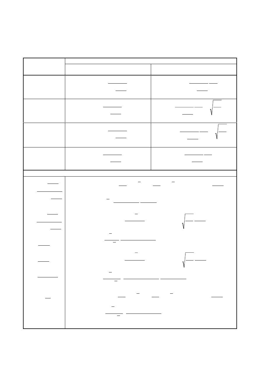
3DJH
Final draft
SU(1
7 May 2003
$QQH[$>LQIRUPDWLYH@±0HWKRG,QWHUDFWLRQIDFWRUVN
LM
IRULQWHUDFWLRQ
IRUPXODLQ
7DEOH$,QWHUDFWLRQIDFWRUVN
LM
Design assumptions
Interaction factors
elastic cross-sectional properties
class 3, class 4
plastic cross-sectional properties
class 1, class 2
k
yy
y
,
cr
Ed
y
mLT
my
N
N
1
C
C
−
µ
yy
y
,
cr
Ed
y
mLT
my
C
1
N
N
1
C
C
−
µ
k
yz
z
,
cr
Ed
y
mz
N
N
1
C
−
µ
y
z
yz
z
,
cr
Ed
y
mz
w
w
6
,
0
C
1
N
N
1
C
−
µ
k
zy
y
,
cr
Ed
z
mLT
my
N
N
1
C
C
−
µ
z
y
zy
y
,
cr
Ed
z
mLT
my
w
w
6
,
0
C
1
N
N
1
C
C
−
µ
k
zz
z
,
cr
Ed
z
mz
N
N
1
C
−
µ
zz
z
,
cr
Ed
z
mz
C
1
N
N
1
C
−
µ
Auxiliary terms:
y
,
cr
Ed
y
y
,
cr
Ed
y
N
N
1
N
N
1
χ
−
−
=
µ
z
,
cr
Ed
z
z
,
cr
Ed
z
N
N
1
N
N
1
χ
−
−
=
µ
5
,
1
W
W
w
y
,
el
y
,
pl
y
≤
=
5
,
1
W
W
w
z
,
el
z
,
pl
z
≤
=
1
M
Rk
Ed
pl
/
N
N
n
γ
=
C
my
see Table A.2
0
I
I
1
a
y
T
LT
≥
−
=
(
)
y
,
pl
y
,
el
LT
pl
2
max
2
my
y
max
2
my
y
y
yy
W
W
b
n
C
w
6
,
1
C
w
6
,
1
2
1
w
1
C
≥
−
λ
−
λ
−
−
+
=
with
Rd
,
z
,
pl
Ed
,
z
Rd
,
y
,
pl
LT
Ed
,
y
2
0
LT
LT
M
M
M
M
a
5
,
0
b
χ
λ
=
(
)
z
,
pl
z
,
el
y
z
LT
pl
5
z
2
max
2
mz
z
yz
W
W
w
w
6
,
0
c
n
w
C
14
2
1
w
1
C
≥
−
λ
−
−
+
=
with
Rd
,
y
,
pl
LT
my
Ed
,
y
4
z
2
0
LT
LT
M
C
M
5
a
10
c
χ
λ
+
λ
=
(
)
y
,
pl
y
,
el
z
y
LT
pl
5
y
2
max
2
my
y
zy
W
W
w
w
6
,
0
d
n
w
C
14
2
1
w
1
C
≥
−
λ
−
−
+
=
with
Rd
,
z
,
pl
mz
Ed
,
z
Rd
,
y
,
pl
LT
my
Ed
,
y
4
z
0
LT
LT
M
C
M
M
C
M
1
,
0
a
2
d
χ
λ
+
λ
=
(
)
z
,
pl
z
,
el
LT
pl
2
max
2
mz
z
max
2
mz
z
z
zz
W
W
e
n
C
w
6
,
1
C
w
6
,
1
2
1
w
1
C
≥
−
λ
−
λ
−
−
+
=
with
Rd
,
y
,
pl
LT
my
Ed
,
y
4
z
0
LT
LT
M
C
M
1
,
0
a
7
,
1
e
χ
λ
+
λ
=
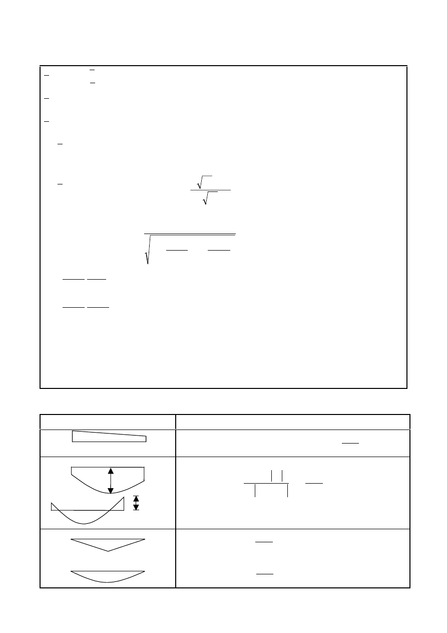
Final draft
3DJH
7 May 2003
SU(1
7DEOH$FRQWLQXHG
λ
λ
=
λ
z
y
max
max
0
λ
= non-dimensional slenderness for lateral-torsional buckling due to uniform bending moment,
i.e.
ψ
y
=1,0 in Table A.2
LT
λ
= non-dimensional slenderness for lateral-torsional buckling
For
0
0
=
λ
:
C
my
= C
my,0
C
mz
= C
mz,0
C
mLT
= 1,0
For
0
0
>
λ
:
(
)
LT
y
LT
y
0
,
my
0
,
my
my
a
1
a
C
1
C
C
ε
+
ε
−
+
=
0
,
mz
mz
C
C
=
−
−
=
T
,
crit
Ed
z
,
crit
Ed
LT
2
my
mLT
N
N
1
N
N
1
a
C
C
y
,
el
Ed
Ed
,
y
y
W
A
N
M
=
ε
for class 1, 2 and 3 cross-sections
y
,
eff
eff
Ed
Ed
,
y
y
W
A
N
M
=
ε
for class 4 cross-sections
N
crit,y
= elastic flexural buckling force about the y-y axis
N
crit,z
= elastic flexural buckling force about the z-z axis
N
crit,T
= elastic torsional buckling force
I
T
= St. Venant torsional constant
I
y
= second moment of area about y-y axis
7DEOH$(TXLYDOHQWXQLIRUPPRPHQWIDFWRUV&
PL
Moment diagram
0
,
mi
C
M
1
ψM
1
1
1
≤
ψ
≤
−
i
.
cr
Ed
i
i
0
,
mi
N
N
)
33
,
0
(
36
,
0
21
,
0
79
,
0
C
−
ψ
+
ψ
+
=
M(x)
M(x)
i
.
cr
Ed
Ed
,
i
2
x
i
2
0
,
mi
N
N
1
)
x
(
M
L
EI
1
C
−
δ
π
+
=
M
i,Ed
(x) is the maximum moment M
y,Ed
or M
z,Ed
_δ
x
| is the maximum member displacement along the member
i
.
cr
Ed
0
,
mi
N
N
18
,
0
1
C
−
=
i
.
cr
Ed
0
,
mi
N
N
03
,
0
1
C
+
=
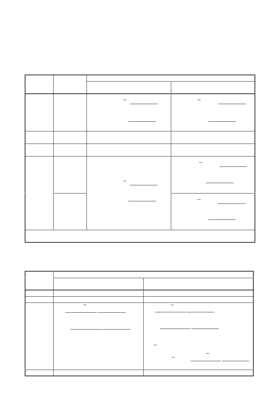
3DJH
Final draft
SU(1
7 May 2003
$QQH[%>LQIRUPDWLYH@±0HWKRG,QWHUDFWLRQIDFWRUVN
LM
IRULQWHUDFWLRQ
IRUPXODLQ
7DEOH%,QWHUDFWLRQIDFWRUVN
LM
IRUPHPEHUVQRWVXVFHSWLEOHWRWRUVLRQDO
GHIRUPDWLRQV
Design assumption
Interaction
factors
Type of
sections
elastic cross-sectional properties
class 3, class 4
plastic cross-sectional properties
class 1, class 2
k
yy
I-sections
RHS-sections
γ
χ
+
≤
γ
χ
λ
+
1
M
Rk
y
Ed
my
1
M
Rk
y
Ed
y
my
/
N
N
6
,
0
1
C
/
N
N
6
,
0
1
C
(
)
γ
χ
+
≤
γ
χ
−
λ
+
1
M
Rk
y
Ed
my
1
M
Rk
y
Ed
y
my
/
N
N
8
,
0
1
C
/
N
N
2
,
0
1
C
k
yz
I-sections
RHS-sections
k
zz
0,6 k
zz
k
zy
I-sections
RHS-sections
0,8 k
yy
0,6 k
yy
I-sections
(
)
γ
χ
+
≤
γ
χ
−
λ
+
1
M
Rk
z
Ed
mz
1
M
Rk
z
Ed
z
mz
/
N
N
4
,
1
1
C
/
N
N
6
,
0
2
1
C
k
zz
RHS-sections
γ
χ
+
≤
γ
χ
λ
+
1
M
Rk
z
Ed
mz
1
M
Rk
z
Ed
z
mz
/
N
N
6
,
0
1
C
/
N
N
6
,
0
1
C
(
)
γ
χ
+
≤
γ
χ
−
λ
+
1
M
Rk
z
Ed
mz
1
M
Rk
z
Ed
z
mz
/
N
N
8
,
0
1
C
/
N
N
2
,
0
1
C
For I- and H-sections and rectangular hollow sections under axial compression and uniaxial bending M
y,Ed
the coefficient k
zy
may be k
zy
= 0.
7DEOH%,QWHUDFWLRQIDFWRUVN
LM
IRUPHPEHUVVXVFHSWLEOHWRWRUVLRQDO
GHIRUPDWLRQV
Design assumptions
Interaction
factors
elastic cross-sectional properties
class 3, class 4
plastic cross-sectional properties
class 1, class 2
k
yy
k
yy
from Table B.1
k
yy
from Table B.1
k
yz
k
yz
from Table B.1
k
yz
from Table B.1
k
zy
(
)
(
)
γ
χ
−
−
≥
γ
χ
−
λ
−
1
M
Rk
z
Ed
mLT
1
M
Rk
z
Ed
mLT
z
/
N
N
25
,
0
C
05
,
0
1
/
N
N
25
,
0
C
05
,
0
1
(
)
(
)
γ
χ
−
−
≥
γ
χ
−
λ
−
1
M
Rk
z
Ed
mLT
1
M
Rk
z
Ed
mLT
z
/
N
N
25
,
0
C
1
,
0
1
/
N
N
25
,
0
C
1
,
0
1
:
4
,
0
for
z
<
λ
(
)
1
M
Rk
z
Ed
mLT
z
z
zy
/
N
N
25
,
0
C
1
,
0
1
6
,
0
k
γ
χ
−
λ
−
≤
λ
+
=
k
zz
k
zz
from Table B.1
k
zz
from Table B.1
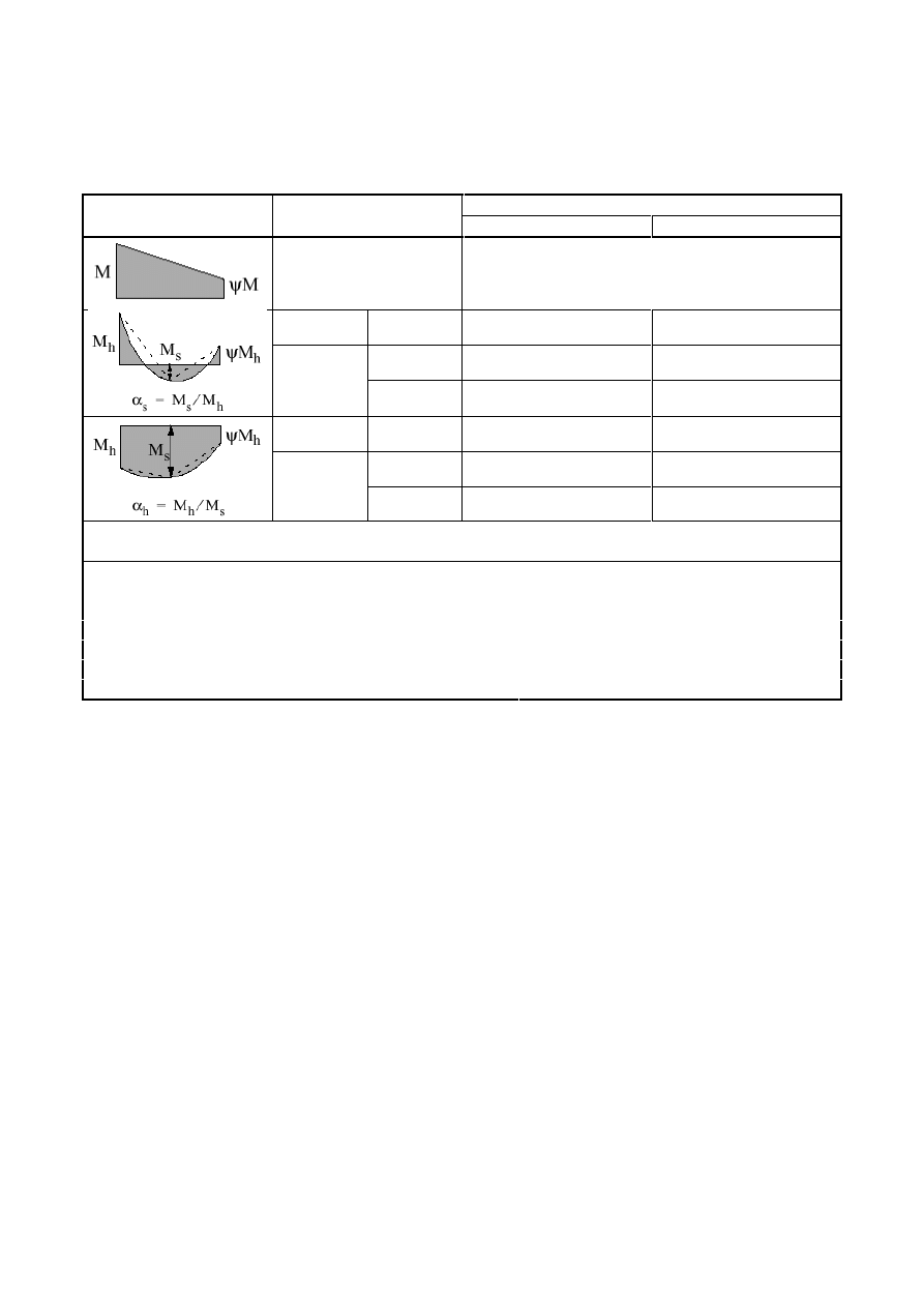
Final draft
3DJH
7 May 2003
SU(1
7DEOH%(TXLYDOHQWXQLIRUPPRPHQWIDFWRUV&
P
LQ7DEOHV%DQG%
C
my
and C
mz
and C
mLT
Moment diagram
range
uniform loading
concentrated load
-1
≤ ψ ≤ 1
0,6 + 0,4
ψ ≥ 0,4
0
≤ α
s
≤ 1
-1
≤ ψ ≤ 1
0,2 + 0,8
α
s
≥ 0,4
0,2 + 0,8
α
s
≥ 0,4
0
≤ ψ ≤ 1
0,1 - 0,8
α
s
≥ 0,4
-0,8
α
s
≥ 0,4
-1
≤ α
s
< 0
-1
≤ ψ < 0
0,1(1-
ψ) - 0,8α
s
≥ 0,4
0,2(-
ψ) - 0,8α
s
≥ 0,4
0
≤ α
h
≤ 1
-1
≤ ψ ≤ 1
0,95 + 0,05
α
h
0,90 + 0,10
α
h
0
≤ ψ ≤ 1
0,95 + 0,05
α
h
0,90 + 0,10
α
h
-1
≤ α
h
< 0
-1
≤ ψ < 0
0,95 + 0,05
α
h
(1+2
ψ)
0,90 - 0,10
α
h
(1+2
ψ)
For members with sway buckling mode the equivalent uniform moment factor should be taken C
my
= 0,9 or
C
Mz
= 0,9 respectively.
C
my
, C
mz
and C
mLT
shall be obtained according to the bending moment diagram between the relevant braced
points as follows:
moment factor
bending axis
points braced in direction
C
my
y-y
z-z
C
mz
z-z
y-y
C
mLT
y-y
y-y

3DJH
Final draft
SU(1
7 May 2003
$QQH[$%>LQIRUPDWLYH@±$GGLWLRQDOGHVLJQSURYLVLRQV
$% 6WUXFWXUDODQDO\VLVWDNLQJDFFRXQWRIPDWHULDOQRQOLQHDULWLHV
(1)B In case of material non-linearities the action effects in a structure may be determined by incremental
approach to the design loads to be considered for the relevant design situation.
(2)B In this incremental approach each permanent or variable action should be increased proportionally.
$% 6LPSOLILHGSURYLVLRQVIRUWKHGHVLJQRIFRQWLQXRXVIORRUEHDPV
(1)B For continuous beams with slabs in buildings without cantilevers on which uniformly distributed loads
are dominant, it is sufficient to consider only the following load arrangements:
a) alternative spans carrying the design permanent and variable load (
γ
G
G
k
+
γ
Q
Q
k
), other spans carrying
only the design permanent load
γ
G
G
k
b) any two adjacent spans carrying the design permanent and variable loads (
γ
G
G
k
+
γ
Q
Q
k
), all other spans
carrying only the design permanent load
γ
G
G
k
127( a) applies to sagging moments, b) to hogging moments.
127( This annex is intended to be transferred to EN 1990 in a later stage.
Final draft
3DJH
7 May 2003
SU(1
$QQH[ %% >LQIRUPDWLYH@ ± %XFNOLQJ RI FRPSRQHQWV RI EXLOGLQJ
VWUXFWXUHV
%% )OH[XUDOEXFNOLQJRIPHPEHUVLQWULDQJXODWHGDQGODWWLFHVWUXFWXUHV
%% *HQHUDO
(1)B For chord members generally and for out-of-plane buckling of web members, the buckling length L
cr
may be taken as equal to the system length L, unless a smaller value can be justified by analysis.
(2)B The buckling length L
cr
of an I or H section chord member may be taken as 0,9L for in-plane buckling
and 1,0L for out-of-plane buckling, unless a smaller value is justified by analysis.
(3)B Web members may be designed for in-plane buckling using a buckling length smaller than the system
length, provided the chords supply appropriate end restraint and the end connections supply appropriate
fixity (at least 2 bolts if bolted).
(4)B Under these conditions, in normal triangulated structures the buckling length L
cr
of web members for
in-plane buckling may be taken as 0,9L, except for angle sections, see BB.1.2.
%% $QJOHVDVZHEPHPEHUV
(1)B Provided that the chords supply appropriate end restraint to web members made of angles and the end
connections of such web members supply appropriate fixity (at least two bolts if bolted), the eccentricities
may be neglected and end fixities allowed for in the design of angles as web members in compression. The
effective slenderness ratio
λ
eff
may be obtained as follows:
v
v
,
eff
7
,
0
35
,
0
λ
+
=
λ
for buckling about v-v axis
y
y
,
eff
7
,
0
50
,
0
λ
+
=
λ
for buckling about y-y axis
(BB.1)
z
z
,
eff
7
,
0
50
,
0
λ
+
=
λ
for buckling about z-z axis
where
λ is as defined in 6.3.1.2.
(2)B When only one bolt is used for end connections of angle web members the eccentricity should be
taken into account using 6.2.9 and the buckling length
/
FU
should be taken as equal to the system length L.
%% +ROORZVHFWLRQVDVPHPEHUV
(1)B The buckling length L
cr
of a hollow section chord member may be taken as 0,9L for both in-plane and
out-of-plane buckling, where L is the system length for the relevant plane. The in-plane system length is the
distance between the joints. The out-of-plane system length is the distance between the lateral supports,
unless a smaller value is justified by analysis.
(2)B The buckling length L
cr
of a hollow section brace member (web member) with bolted connections may
be taken as 1,0L for both in-plane and out-of-plane buckling.
(3)B For latticed girders with parallel chords and braces, for which the brace to chord diameter or width
ratio
β is less than 0,6 the buckling length L
cr
of a hollow section brace member without cropping or
flattening, welded around its perimeter to hollow section chords, may generally be taken as 0,75L for both
in-plane and out-of-plane buckling, unless smaller values may be justified by tests or by calculations.
127( The National Annex may give more information on buckling lengths.

3DJH
Final draft
SU(1
7 May 2003
%% &RQWLQXRXVUHVWUDLQWV
%% &RQWLQXRXVODWHUDOUHVWUDLQWV
(1)B If trapezoidal sheeting according to EN 1993-1-3 is connected to a beam and the condition expressed
by equation (BB.2) is met, the beam at the connection may be regarded as being laterally restrained in the
plane of the sheeting.
2
2
2
2
z
t
2
2
w
h
70
h
25
,
0
L
EI
GI
L
EI
S
π
+
+
π
≥
(BB.2)
where S
is the shear stiffness (per unit of beam length) provided by the sheeting to the beam regarding its
deformation in the plane of the sheeting to be connected to the beam at each rib.
I
w
is the warping constant
I
t
is the torsion constant
I
z
is the second moment of area of the cross section about the minor axis of the cross section
L
is the beam length
h
is the depth of the beam
If the sheeting is connected to a beam at every second rib only, S should be substituted by 0,20S.
127(Eqation (BB.2) may also be used to determine the lateral stability of beam flanges used in
combination with other types of cladding than trapezoidal sheeting, provided that the connections are
of suitable design.
%% &RQWLQXRXVWRUVLRQDOUHVWUDLQWV
(1)B A beam may be considered as sufficiently restraint from torsional deformations if
υ
ϑ
ϑ
>
K
K
EI
M
C
z
2
k
,
pl
k
,
(BB.3)
where C
ϑ,k
= rotational stiffness (per unit of beam length) provided to the beam by the stabilising
continuum (e.g. roof structure) and the connections
K
= 0,35 for elastic analysis
K
= 1,00 for plastic analysis
K
ϑ
= factor for considering the moment distribution see Table BB.1 and the type of restraint
M
pl,k
= characteristic value of the plastic moment of the beam
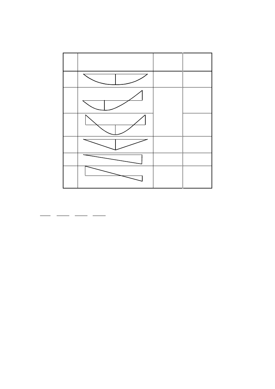
Final draft
3DJH
7 May 2003
SU(1
7DEOH%%)DFWRU.
ϑ
IRUFRQVLGHULQJWKHPRPHQWGLVWULEXWLRQDQGWKHW\SHRI
UHVWUDLQW
Case
Moment distribution
without
translational
restraint
with
translational
restraint
1
M
4,0
0
2a
M
M
0,12
2b
M
M
M
3,5
0,23
3
M
2,8
0
4
M
1,6
1,0
5
M
R
M
R
#
-0,3
1,0
0,7
(2)B The rotational stiffness provided by the stabilising continuum to the beam may be calculated from
k
,
D
k
,
C
k
,
R
k
,
C
1
C
1
C
1
C
1
ϑ
ϑ
ϑ
ϑ
+
+
=
(BB.4)
where C
ϑR,k
= rotational stiffness (per unit of the beam length) provided by the stabilising continuum to
the beam assuming a stiff connection to the member
C
ϑC,k
= rotational stiffness (per unit of the beam length) of the connection between the beam and
the stabilising continuum
C
ϑD,k
= rotational stiffness (per unit of the beam length) deduced from an analysis of the
distorsional deformations of the beam cross sections, where the flange in compression is
the free one; where the compression flange is the connected one or where distorsional
deformations of the cross sections may be neglected (e.g. for usual rolled profiles)
C
ϑD,k
=
∞
127( For more information see EN 1993-1-3.
%% 6WDEOH OHQJWKV RI VHJPHQW FRQWDLQLQJ SODVWLF KLQJHV IRU RXWRISODQH
EXFNOLQJ
%% 8QLIRUPPHPEHUVPDGHRIUROOHGVHFWLRQVRUHTXLYDOHQWZHOGHG,VHFWLRQV
%% 6WDEOHOHQJWKVEHWZHHQDGMDFHQWODWHUDOUHVWUDLQWV
(1)B Lateral torsional buckling effects may be ignored where the length L of the segment of a member
between the restrained section at a plastic hinge location and the adjacent lateral restraint is not greater than
L
m
, where:
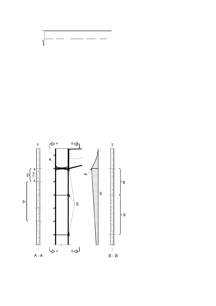
3DJH
Final draft
SU(1
7 May 2003
2
y
t
2
y
,
pl
2
1
Ed
z
m
235
f
AI
W
C
756
1
A
N
4
,
57
1
i
38
L
+
=
(BB.5)
where N
Ed
is the design value of the compression force [N] in the member
A
is the cross section area [mm²] of the member
W
pl,y
is the plastic section modulus of the member
I
t
is the torsion constant of the member
f
y
is the yield strength in [N/mm²]
provided that the member is restrained at the hinge as required by 6.3.5 and that the other end of the segment
is restrained
–
either by a lateral restraint to the compression flange where one flange is in compression throughout the
length of the segment,
–
or by a torsional restraint,
–
or by a lateral restraint at the end of the segment and a torsional restraint to the member at a distance that
satisfies the requirements for L
s
,
see Figure BB.1, Figure BB.2 and Figure BB3.
127( In general L
s
is greater than L
m
.
WHQVLRQIODQJH
SODVWLFVWDEOHOHQJWKVHH
%%
HODVWLFVHFWLRQVHH
SODVWLFKLQJH
UHVWUDLQWV
EHQGLQJPRPHQWGLDJUDP
FRPSUHVVLRQIODQJH
SODVWLFZLWKWHQVLRQIODQJH
UHVWUDLQWVWDEOHOHQJWK /
V
VHH
%%HTXDWLRQ%%RU
%%
HODVWLFZLWKWHQVLRQIODQJH
UHVWUDLQWVHH
χ
DQG
χ
/7
IURP
1
FU
DQG0
FU
LQFOXGLQJWHQVLRQ
IODQJHUHVWUDLQW
)LJXUH%%&KHFNVLQDPHPEHUZLWKRXWDKDXQFK
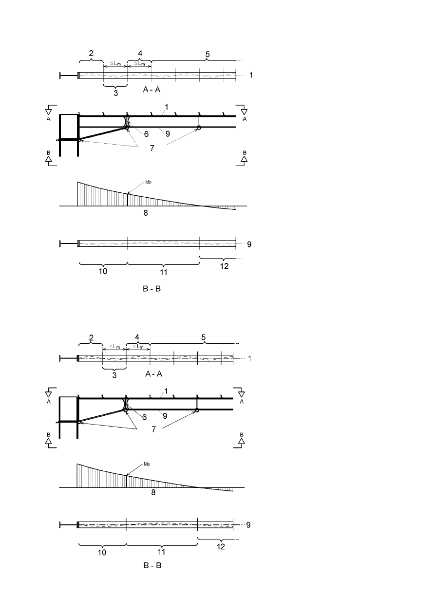
Final draft
3DJH
7 May 2003
SU(1
WHQVLRQIODQJH
HODVWLFVHFWLRQVHH
SODVWLFVWDEOHOHQJWKVHH
%%RUHODVWLFVHH
%
SODVWLFVWDEOHOHQJWKVHH
%%
HODVWLFVHFWLRQVHH
SODVWLFKLQJH
UHVWUDLQWV
EHQGLQJPRPHQWGLDJUDP
FRPSUHVVLRQIODQJH
SODVWLFVWDEOHOHQJWKVHH
%%RUHODVWLFVHH
%
SODVWLFVWDEOHOHQJWKVHH
%%
HODVWLFVHFWLRQVHH
χ
DQG
χ
/7
IURP1
FU
DQG0
FU
LQFOXGLQJ
WHQVLRQIODQJHUHVWUDLQW
)LJXUH%%&KHFNVLQDPHPEHUZLWKDWKUHHIODQJHKDXQFK
WHQVLRQIODQJH
HODVWLFVHFWLRQVHH
SODVWLFVWDEOHOHQJWKVHH
%%
SODVWLFVWDEOHOHQJWKVHH
%%
HODVWLFVHFWLRQVHH
SODVWLFKLQJH
UHVWUDLQWV
EHQGLQJPRPHQWGLDJUDP
FRPSUHVVLRQIODQJH
SODVWLFVWDEOHOHQJWKVHH
%%
SODVWLFVWDEOHOHQJWKVHH
%%
HODVWLFVHFWLRQVHH
χ
DQG
χ
/7
IURP1
FU
DQG0
FU
LQFOXGLQJ
WHQVLRQIODQJHUHVWUDLQW
)LJXUH%%&KHFNVLQDPHPEHUZLWKDWZRIODQJHKDXQFK
3DJH
Final draft
SU(1
7 May 2003
%% 6WDEOHOHQJWKEHWZHHQWRUVLRQDOUHVWUDLQWV
(1)B Lateral torsional buckling effects may be ignored where the length L of the segment of a member
between the restrained section at a plastic hinge location and the adjacent torsional restraint subject to a
constant moment is not greater than L
k
, provided that
–
the member is restrained at the hinge as required by 6.3.5 and
–
there are one or more intermediate lateral restraints between the torsional restraints at a spacing that
satisfies the requirements for L
m
, see BB.3.1.1,
where
1
t
h
E
f
4
,
5
i
t
h
E
f
600
4
,
5
L
2
f
y
z
f
y
k
−
+
=
(BB.6)
(2)B Lateral torsional buckling effects may be ignored where the length L of the segment of a member
between the restrained section at a plastic hinge location and the adjacent torsional restraint subject to a
linear moment gradient and axial compression is not greater than L
s
, provided that
–
the member is restrained at the hinge as required by 6.3.5 and
–
there are one or more intermediate lateral restraints between the torsional restraints at a spacing that
satisfies the requirements for L
m
, see BB.3.1.1,
where
+
=
Ed
Rk
,
y
,
N
Rk
,
y
,
pl
k
m
s
aN
M
M
L
C
L
(BB.7)
C
m
is the modification factor for linear moment gradient, see BB.3.3.1;
a
is the distance between the centroid of the member with the plastic hinge and the centroid of
the restraint members;
M
pl,y,Rk
is the characteristic plastic moment resistance of the cross section about the y-y axis
M
N,y,Rk
is the characteristic plastic moment resistance of the cross section about the y-y axis with
reduction due to the axial force N
Ed
(3)B Lateral torsional buckling effects may be ignored where the length L of a segment of a member
between the restrained section at a plastic hinge location and the adjacent torsional restraint subject to a non
linear moment gradient and axial compression is not greater than L
s
, provided that
–
the member is restrained at the hinge as required by 6.3.5 and
–
there are one or more intermediate lateral restraints between the torsional restraints at a spacing that
satisfies the requirements for L
m
, see BB3.1.1
where
k
n
s
L
C
L
=
(BB.8)
C
n
is the modification factor for non-linear moment gradient, see BB.3.3.2,
see Figure BB.1, Figure BB.2 and Figure BB.3.
Final draft
3DJH
7 May 2003
SU(1
%% +DXQFKHG RU WDSHUHG PHPEHUV PDGH RI UROOHG VHFWLRQV RU HTXLYDOHQW ZHOGHG ,
VHFWLRQV
%% 6WDEOHOHQJWKEHWZHHQDGMDFHQWODWHUDOUHVWUDLQWV
(1)B Lateral torsional buckling effects may be ignored where the length L of the segment of a member
between the restrained section at a plastic hinge location and the adjacent lateral restraint is not greater than
L
m
, where
–
for three flange haunches (see Figure BB.2)
2
y
t
2
y
,
pl
2
1
Ed
z
m
235
f
AI
W
C
756
1
A
N
4
,
57
1
i
38
L
+
=
(BB.9)
–
for two flange haunches (see Figure BB.3)
2
y
t
2
y
,
pl
2
1
Ed
z
m
235
f
AI
W
C
756
1
A
N
4
,
57
1
i
38
85
,
0
L
+
=
(BB.10)
where N
Ed
is the design value of the compression force [N] in the member
t
2
y
,
pl
AI
W
is the maximum value in the segment
A
is the cross sectional area [mm²] at the location where
t
2
y
,
pl
AI
W
is a maximum of the tapered
member
W
pl,y
is the plastic section modulus of the member
I
t
is the torsional constant of the member
f
y
is the yield strength in [N/mm²]
i
z
is the minimum value of the radius of gyration in the segment
provided that the member is restrained at the hinge as required by 6.3.5 and that the other end of segment is
restrained
–
either by a lateral restraint to the compression flange where one flange is in compression throughout the
length of the segment,
–
or by a torsional restraint,
–
or by a lateral restraint at the end of the segment and a torsional restraint to the member at a distance that
satisfies the requirements for L
s
.
%% 6WDEOHOHQJWKEHWZHHQWRUVLRQDOUHVWUDLQWV
(1)B For non uniform members with constant flanges under linear or non-linear moment gradient and axial
compression, lateral torsional buckling effects may be ignored where the length L of the segment of a
member between the restrained section at a plastic hinge location and the adjacent torsional restraint is not
greater than L
s
, provided that
–
the member is restrained at the hinge as required by 6.3.5 and
–
there are one or more intermediate lateral restraints between the torsional restraints at a spacing that
satisfies the requirements for L
m
, see BB.3.2.1,
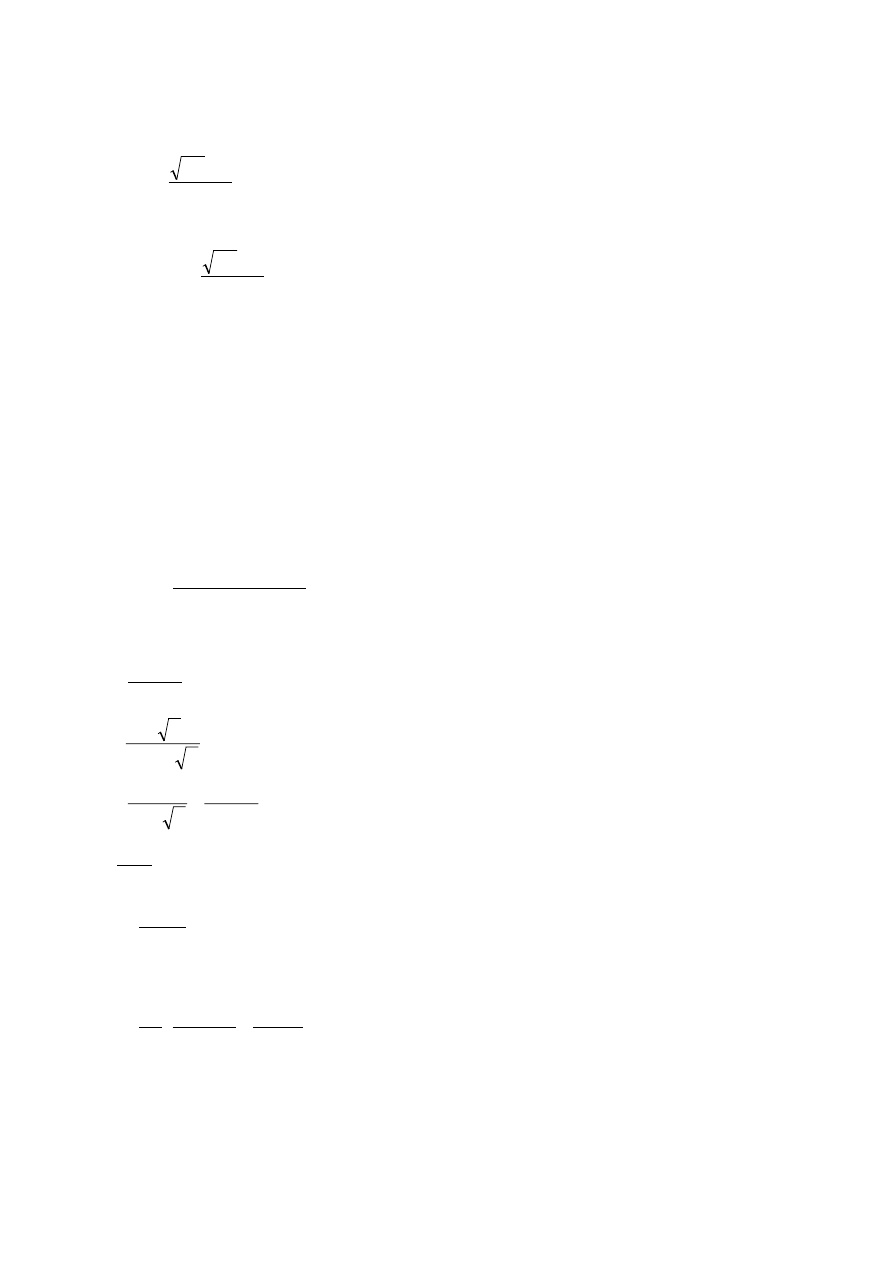
3DJH
Final draft
SU(1
7 May 2003
where
–
for three flange haunches (see Figure BB.2)
c
L
C
L
k
n
s
=
(BB.11)
–
for two flange haunches (see Figure BB.3)
c
L
C
85
,
0
L
k
n
s
=
(BB.12)
where L
k
is the length derived for a uniform member with a cross-section equal to the shallowest section,
see BB.3.1.2, using the minimum value for i
z
in the segment and the maximum value of (h/t
f
) in
the segment
C
n
see BB.3.3.2
c is the taper factor defined in BB.3.3.3
%% 0RGLILFDWLRQIDFWRUVIRUPRPHQWJUDGLHQWVLQPHPEHUVODWHUDOO\UHVWUDLQHGDORQJWKH
WHQVLRQIODQJH
%% /LQHDUPRPHQWJUDGLHQWV
(1)B The modification factor C
m
may be determined from
2
t
2
t
1
0
m
B
B
B
1
C
β
+
β
+
=
(BB.13)
in which
η
+
η
+
=
20
1
10
1
B
0
η
+
π
η
=
10
5
B
1
η
+
−
η
π
+
=
20
1
5
,
0
1
5
,
0
B
2
crT
crE
N
N
=
η
2
t
z
2
crE
L
EI
N
π
=
t
L
is the distance between the torsional restraints
+
π
+
π
=
t
2
t
w
2
2
t
2
z
2
2
s
crT
GI
L
EI
L
a
EI
i
1
N
is the elastic critical buckling force for an I-section between
restraints to both flanges at spacing L
t
with intermediate lateral
restraints to the tension flange.
2
2
z
2
y
2
s
a
i
i
i
+
+
=
where a is the distance between the centroid of the member and the centroid of the restraining members,
such as purlins restraining rafters
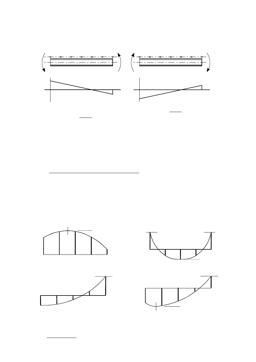
Final draft
3DJH
7 May 2003
SU(1
β
t
is the ratio of the algebraically smaller end moment to the larger end moment. Moments that
produce compression in the non-restrained flange should be taken as positive. If the ratio is less
than –1,0 the value of
β
t
should be taken as –1,0, see Figure BB.4.
100
100
200
200
–
–
+
+
5
,
0
200
100
t
−
=
+
−
=
β
0
,
1
thus
0
,
1
but
2
100
200
t
t
t
−
=
β
−
≥
β
−
=
+
−
=
β
)LJXUH%%9DOXHRIβ
W
%% 1RQOLQHDUPRPHQWJUDGLHQWV
(1)B The modification factor C
n
may be determined from
(
)
[
]
E
S
5
4
3
2
1
n
R
R
2
R
R
3
R
4
R
3
R
12
C
−
+
+
+
+
+
=
(BB.14)
in which R
1
to R
5
are the values of R according to (2)B at the ends, quarter points and mid-length, see Figure
BB.5, and only positive values of R should be included.
In addition, only positive values of (R
S
– R
E
) should be included, where
–
R
E
is the greater of R
1
or R
5
–
R
s
is the maximum value of R anywhere in the length L
y
R
1
R
2
R
3
R
4
R
5
R
E
R
S
R
E
R
E
R
1
R
5
R
4
3
R
R
2
R
S
E
= R
R
5
R
4
3
R
R
2
R
1
R
S
R
1
R
2
3
R
R
4
R
5
R
E
R
S
)LJXUH%%0RPHQWUDWLRV
(2)B The value of R should be obtained from:
y
,
pl
y
Ed
Ed
,
y
W
f
N
a
M
R
+
=
(BB.15)
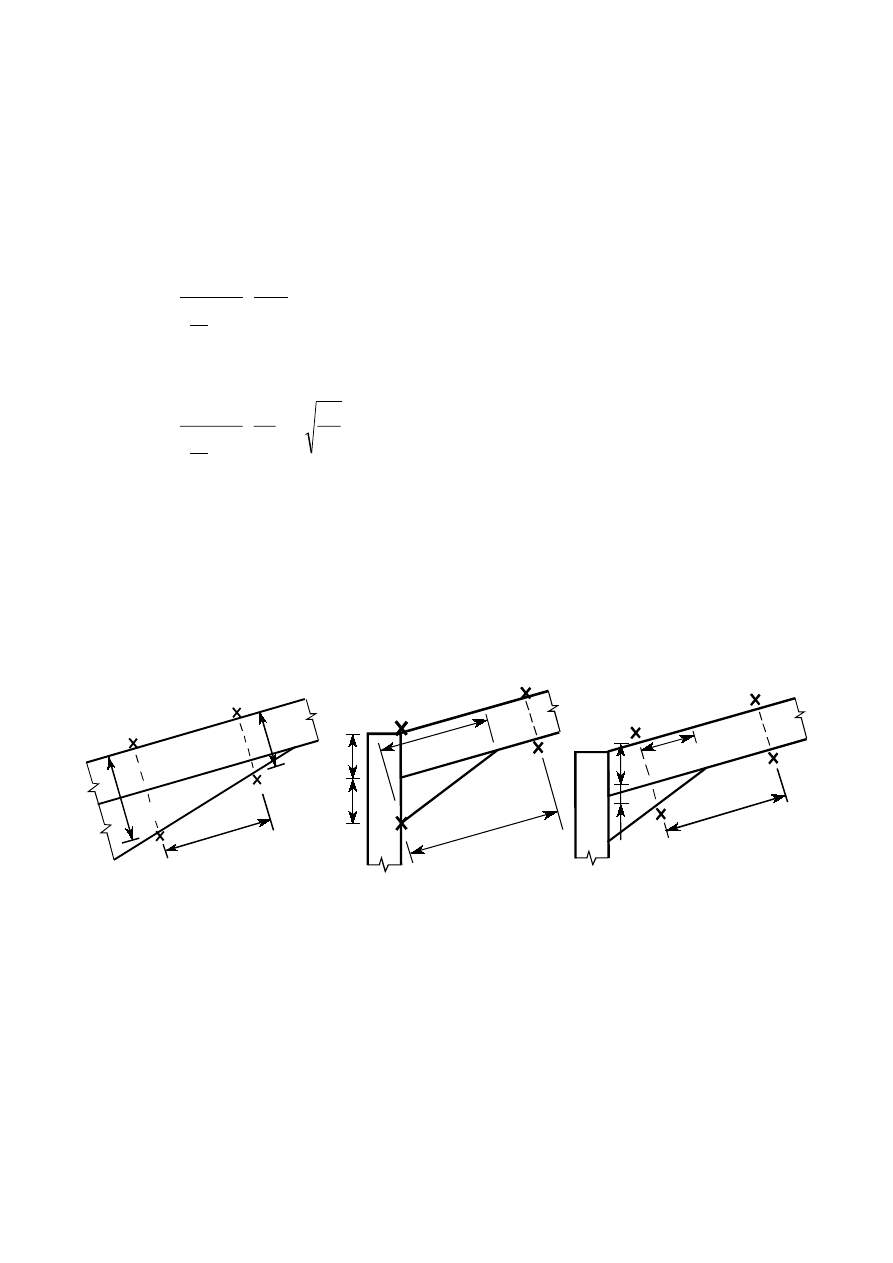
3DJH
Final draft
SU(1
7 May 2003
where a is the distance between the centroid of the member and the centroid of the restraining members,
such as purlins restraining rafters
%% 7DSHUIDFWRU
(1)B For a non uniform member with constant flanges, for which h
EDQGKW
f
WKHWDSHUIDFWRUF
should be obtained as follows:
–
for tapered members or segments:
3
/
2
min
max
f
1
h
h
9
t
h
3
1
c
−
−
+
=
(BB.16)
–
for haunched members or segments:
y
h
3
/
2
s
h
f
L
L
h
h
9
t
h
3
1
c
−
+
=
(BB.17)
where h
h
is the additional depth of the haunch or taper, see Figure BB.6;
h
max
is the maximum depth of cross-section within the length L
y
, see Figure BB.6;
h
min
is the minimum depth of cross-section within the length L
y
, see Figure BB.6;
h
s
is the vertical depth of the un-haunched section, see Figure BB.6;
L
h
is the length of haunch within the length L
y
, see Figure BB.6;
L
y
is the length between points at which the compression flange is laterally restrained;
L
y
h
min
h
max
h
h
h
s
L
h
L
y
h
h
h
s
L
h
L
y
(a) Tapered segment
(b) Haunched segment
(c) Haunched segment
x = restraint
)LJXUH%%'LPHQVLRQVGHILQLQJWDSHUIDFWRU
Wyszukiwarka
Podobne podstrony:
04 HBT Slup EC3
dla studentow hbt wezly EC3
A Biegus Proj wg EC3 CZĘŚĆ 7 Wymiarowanie EC
KM cwiczenia sruby EC3 stud
Obliczanie stężeń wg EC3 2
A Biegus Proj wg EC3 CZĘŚĆ 8 Stal i wyroby
KM W class 4 EC3 ENG stud
KM W 14 slupy osiowo EC3 stud
01 hbt platew EC3
KM W 18 slupy mimosrodowe EC3 stud
KM EC3 Sciskanie przyk│ady do sam rozw
KM EC3 Sciskanie Przyk│ady tresc zadan
KM EC3 Sciskanie OKNO
brandschutz im stahlbau bock (2003) ec3 wpływ ciepła na konstrukcję 7BVH577SNW362SBRPCJCFE6L2AP3SM
04 HBT Slup EC3
Buckling AISC & EC3 comparisons
więcej podobnych podstron