
Re m o v i n g a n d
I n s t a l l i n g Pa r t s
Before You Remove or Replace Parts
System Components
Palm Rest and Display Cover Inserts
Hard Drive
Memory Modules, Mini PCI Card, and Modem
Keyboard
Display, Display Assembly, Display Latch, and Hinge
Palm Rest
Microprocessor Thermal Cooling Assembly
Microprocessor
Hybrid Cooling Fan
Reserve Battery
Speakers
System Board
Battery and Module Bay Latches

2
Removing and Installing Parts
www
.dell.com | support.dell.com

3
Before You Remove or Replace Parts
Preparing to Work Inside the Computer
CAUTION: Only a certified service technician should perform
repairs on your computer. Damage due to servicing that is not
authorized by Dell is not covered by your warranty. Read and
follow applicable safety instructions in the
Owner's Manual
that
came with the computer.
NOTICE: To avoid damaging the computer, perform the following steps before
you begin working inside the computer.
1
Ensure that the work surface is clean to prevent scratching the
computer cover.
2
Save any work in progress and exit all open programs.
3
Turn off the computer and all attached devices.
HINT: Ensure that
the computer is turned off
and not in suspend mode
or hibernate mode. If you
cannot shut down the
computer using the
computer operating
system, press and hold the
power button for 4
seconds.
4
Ensure that the computer is undocked.
5
Disconnect the computer from the electrical outlet.
6
To avoid possible damage to the system board, wait 10 to 20 seconds
and then disconnect any attached devices.
7
Disconnect all other external cables from the computer.
8
Remove any installed PC Cards or plastic blanks from the PC Card
slot.
9
Close the display and turn the computer upside down on a flat work
surface.
NOTICE: To avoid damaging the system board, you must remove the main
battery and secondary battery (if present) before you service the computer.
10
Remove the primary battery from the battery bay and the secondary
battery from the module bay, if a secondary battery is in use.
11
Remove any device installed in the module bay.
12
To dissipate any static electricity while you work, use a wrist grounding
strap or periodically touch an unpainted metal surface.
13
Handle components and cards with care. Do not touch the
components or contacts on a card. Hold a card by it edges or by its
metal mounting bracket. Hold a component such as a microprocessor
by its edges, not by its pins.
4
www
.dell.com | support.dell.com
Recommended Tools
The procedures in this manual require the following tools:
• #1 magnetized Phillips screwdriver
• ¼-inch flat-blade screwdriver
• Small plastic scribe
• Microprocessor extractor
• Flash BIOS update program CD
1
back
2
right
3
front
4
left
3
1
2
4
5
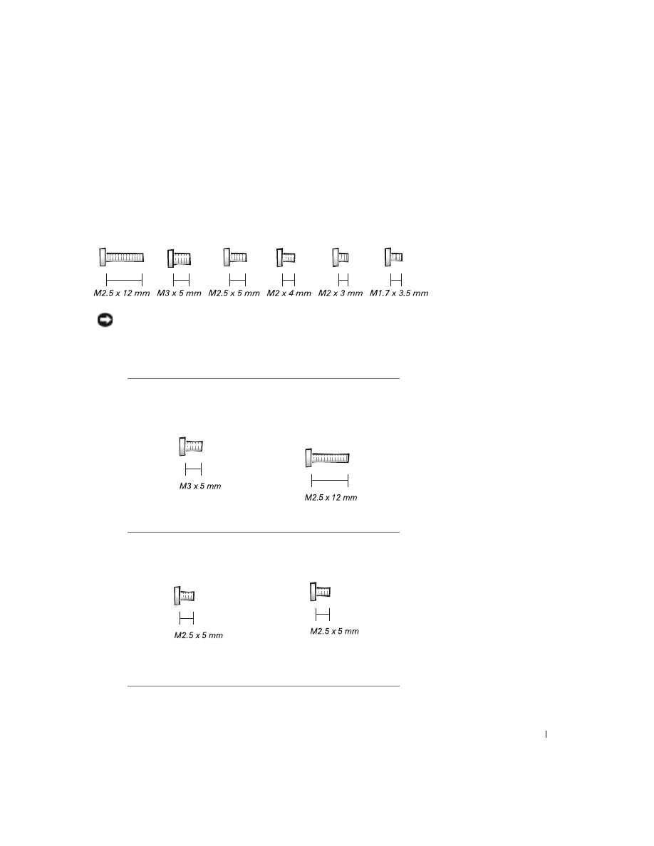
Screw Identification
When you are removing and replacing components, photocopy the place
mat as a tool to lay out and keep track of the screws. The place mat provides
the number of screws and their sizes.
NOTICE: When reinstalling a screw, you must use a screw of the correct
diameter and length. Make sure that the screw is properly aligned with its
corresponding hole, and avoid over tightening.
Hard Drive Door:
(1 each)
Keyboard to
Bottom Case:
(5 each)
Display Bezel:
(6 each)
Rubber Screw Covers (6 each)
Hinge Bracket to Bottom Case:
(5 each)
6
www
.dell.com | support.dell.com
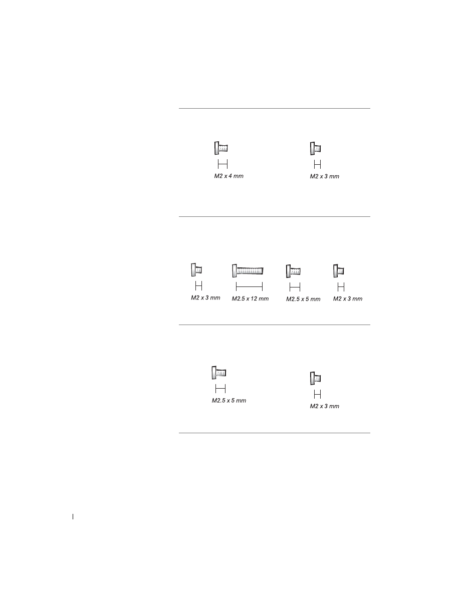
Display Assembly to Top Cover:
(5 each)
Display-Feed Flex Cable:
(4 each)
Palm Rest to
Bottom Case:
(5 each) (3 each)
Hybrid Cooling Fan:
(2 each) (1 each)
System Board to Bottom Case:
(10 each)
Modem to
System Board:
(2 each)
7
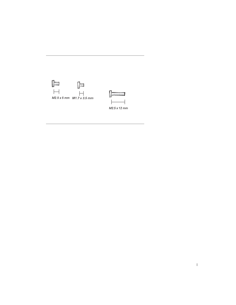
Display Latch:
(2 each) (2 each)
Memory Module Cover:
(2 captive screws)
(1 each)
The single screw is one of the
five keyboard screws.

8
www
.dell.com | support.dell.com
9
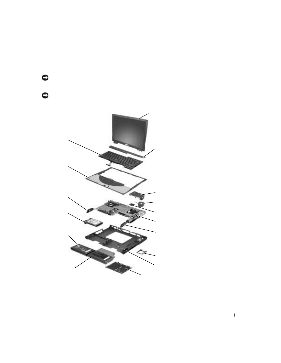
System Components
NOTICE: Only a certified service technician should perform repairs on your
computer. Damage due to servicing that is not authorized by Dell is not covered
by your warranty.
NOTICE: Unless otherwise noted, each procedure in this manual assumes that
a part can be installed by performing the removal procedure in reverse order.
1
15
12
9
6
13
16
2
4
3
14
7
11
10
8
5

10
www
.dell.com | support.dell.com
1
top cover display assembly
9
bottom case assembly
2
center control cover
10
memory module cover
3
thermal cooling assembly
11
module bay device
4
hybrid cooling fan
12
main battery
5
microprocessor module
13
hard drive
6
system board
14
left speaker/antenna
assembly
7
right speaker/antenna
assembly
15
palm rest assembly
8
fan guard
16
keyboard
11
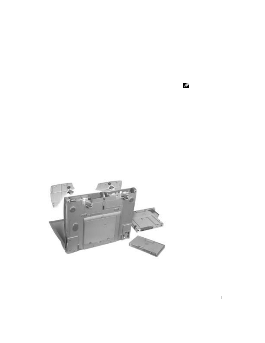
Palm Rest and Display Cover Inserts
Palm Rests
HINT: Complete
instructions for installing
the palm rests are
included with the optional
color inserts.
1
Save and close any open files, exit any open programs, and shut down
the computer.
2
If the computer is connected to a docking device (docked), undock it.
See the documentation that came with your docking device for
instructions.
3
Keep the display open and tilt the computer back so that you can
access the bottom of the computer.
4
Slide and hold the latch release on the left side, and remove any device
installed in the module bay.
5
Slide and hold the latch release on the right side, and remove any
battery installed in the battery bay.
6
Locate the orange palm rest removal buttons. Firmly press the buttons
with the eraser end of a pencil (or a dull utensil smaller than your
finger) to release the palm rests.
7
Remove the palm rests.
12
www
.dell.com | support.dell.com
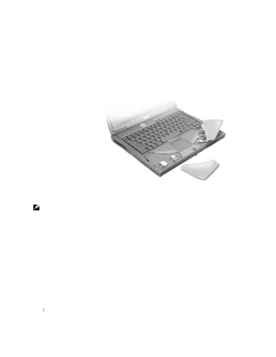
8
To replace the palm rests, insert the tabs on the inside edge of the
palm rest into the slots on the computer. Then press along the outside
edges of the palm rest until it snaps into place.
Repeat the process on each side.
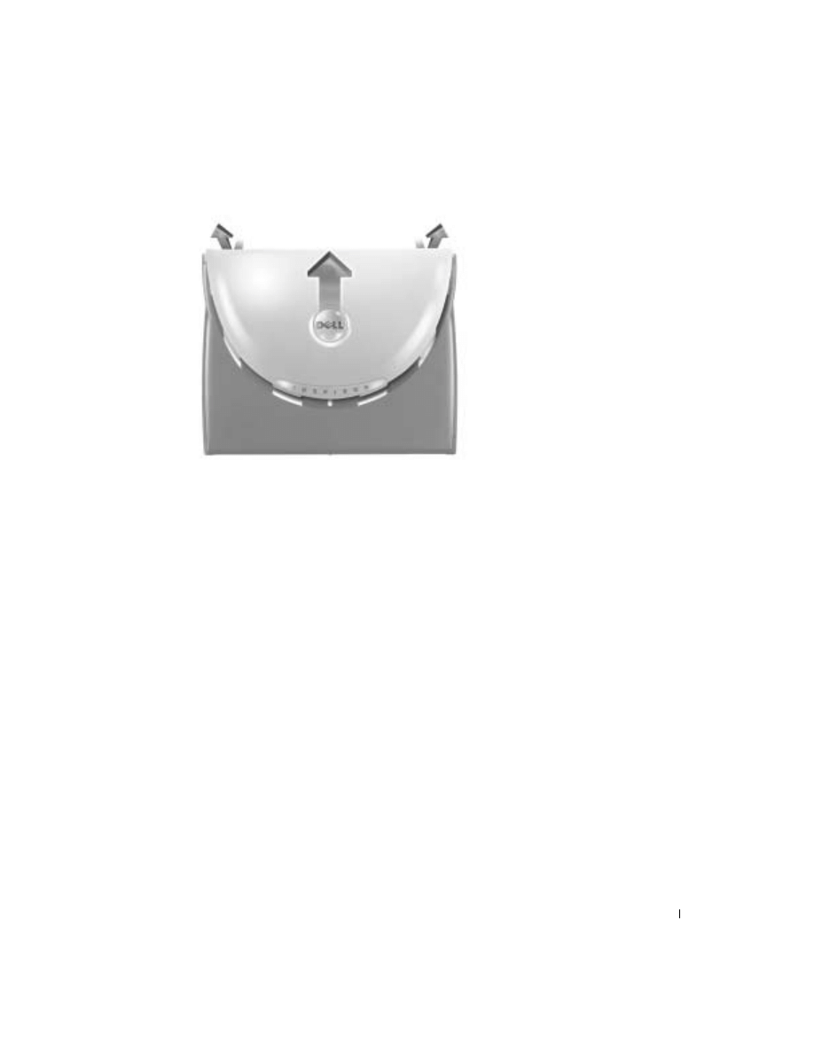
Display Cover
HINT: Complete
instructions for installing
the display cover are
included with the optional
color inserts.
1
Slide your index fingers under the straight edge of the display cover
until the cover pops out.
2
Slide the display cover towards the back of the computer.
3
Use your fingers to release the cover completely, and remove it.
13
4
To replace the display cover, bend it slightly to insert the four tabs on
the rounded edge of the cover into the slots on the top of the
computer.
5
Press the cover along the straight edge at the back of the computer
until it snaps into place.
6
Firmly press the Dell™ logo until it snaps into place. Press above both
hinge covers to engage the final snaps.

14
www
.dell.com | support.dell.com

15
Hard Drive
Removing the Hard Drive
CAUTION: If you remove the hard drive from the computer when
the drive is hot,
do not touch
the metal housing of the hard drive.
NOTICE: Disconnect the computer and any attached devices from electrical
outlets, and remove any installed batteries.
NOTICE: The hard drive is very sensitive to shock. Handle the hard drive by
its edges (do not squeeze the top of the hard drive case), and avoid dropping it.
NOTICE: Read “Preparing to Work Inside the Computer” before performing
the following procedure.
NOTICE: To prevent data loss, turn off your computer before removing the
hard drive. Do not remove the hard drive while the computer is running, in
standby mode, or in hibernate mode.
1
Save and close any open files, exit any open programs, and shut down
the computer.
2
Ground yourself by touching a metal connector on the back of the
computer.
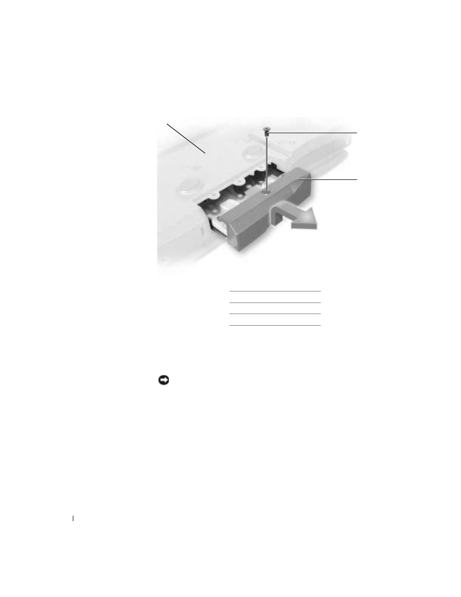
3
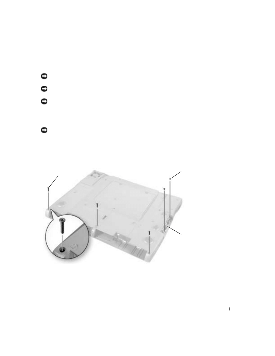
Turn the computer over. Remove the M3 x 5-mm screw from the hard
drive door.
16
www
.dell.com | support.dell.com
4
Lift the hard drive door until you hear a click.
5
Slide the hard drive out of the computer.
Replacing the Hard Drive
NOTICE: Use firm and even pressure to slide the hard drive into place. If you
force the hard drive into place using excessive force, you may damage the
connector.
1
Lift the hard drive door until you hear a click. Push the hard drive into
the drive bay until it is fully seated in the bay.
2
Press the hard drive door down.
3
Replace the M3 x 5-mm screw in the hard drive door.
1 bottom of computer
2 M3 x 5-mm screw
3 hard drive door
3
1
2

17
Memory Modules, Mini PCI Card, and
Modem
Memory Modules
Removing the Memory Module Cover
NOTICE: Disconnect the computer and any attached devices from electrical
outlets, and remove any installed batteries.
NOTICE: To avoid ESD, ground yourself by using a wrist grounding strap or
by touching an unpainted metal surface on the computer.
NOTICE: Read “Preparing to Work Inside the Computer” before performing
the following procedure.
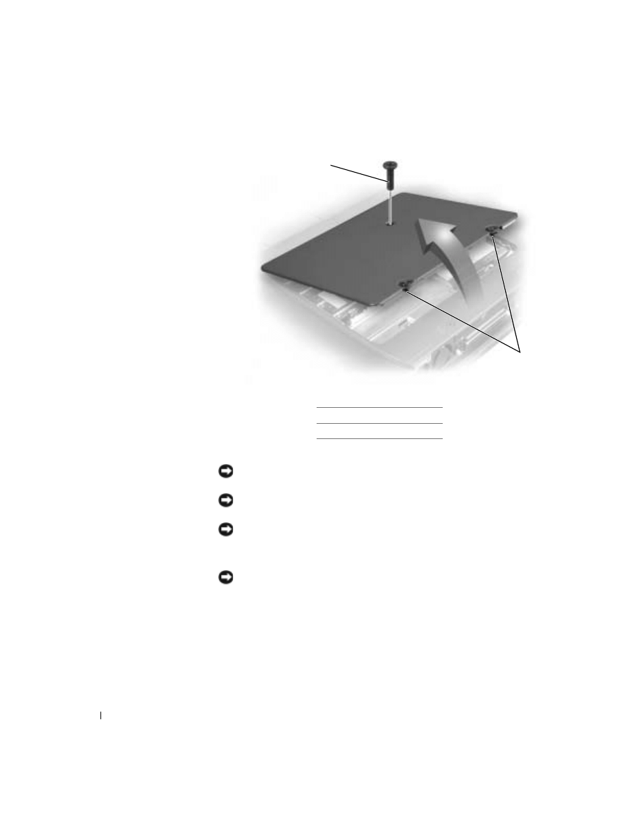
1
Turn the computer over and release the two captive screws from the
cover.
2
Remove the M2.5 x 12-mm screw labeled "circle K" from the cover.
(This screw is also one of the five keyboard screws.)
3
Place your finger under the cover at the indentation and lift and slide
the cover open.
18
www
.dell.com | support.dell.com
Removing the Memory Modules
NOTICE: Disconnect the computer and any attached devices from electrical
outlets, and remove any installed batteries.
NOTICE: To avoid ESD, ground yourself by using a wrist grounding strap or
by touching an unpainted metal surface on the computer.
NOTICE: Read “Preparing to Work Inside the Computer” before performing
the following procedure.
1
Remove the
NOTICE: To prevent damage to the memory module connector, do not use
tools to spread the inner metal tabs that secure the memory module.
2
Use your fingertips to carefully spread apart the inner tabs on each end
of the memory module connector.
The module pops up.
1 M2.5 x 12-mm screw (1)
2 captive screws (2)
2
1
19
3
Lift the memory module out of its connector.
Replacing Memory Modules
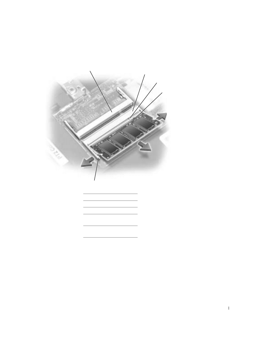
1
If you only have one memory module, install it in the connector
labeled “JDIM1” on the system board. Install a second memory
module in the connector labeled “JDIM2.”
1 JDIM 1 connector
2 JDIM 2 connector
3 keying tab
4 keying notch on memory
module
5 inner tabs (2 per
connector)
4
5
1
2
3

20
www
.dell.com | support.dell.com
HINT: Memory modules
are keyed, or designed to
fit into their connectors,
in only one direction.
NOTICE: The memory module must be inserted at a 45-degree angle to avoid
damaging the connector.
2
Align the notch in the memory module edge connector with the keying
tab in the connector on the system board.
3
Slide the edge connector of the module firmly into the connector at a
45-degree angle, and rotate the module down until you hear a click. If
you do not hear the click, remove the module and reinstall it.
4
Replace the cover and tighten the two captive screws.
Mini PCI Card
You must remove the Mini PCI card before the system board can be
removed.
Removing the Mini PCI Card
NOTICE: Disconnect the computer and any attached devices from electrical
outlets, and remove any installed batteries.
NOTICE: To avoid ESD, ground yourself by using a wrist grounding strap or
by touching an unpainted metal surface on the computer.
NOTICE: Read “Preparing to Work Inside the Computer” before performing
the following procedure.
1
Remove the
2
Disconnect the Mini PCI card from any attached cables.
3
Release the Mini PCI card by spreading the metal securing tabs until
the card pops up slightly.
4
Lift the Mini PCI card out of its connector.
NOTICE: To avoid damaging the Mini PCI card, never place cables on top of
or under the card.
21
Replacing the Mini PCI Card
1
Align the Mini PCI card with the connector at a 45-degree angle, and
press the Mini PCI card into the connector until you hear a click.
NOTICE: The connectors are keyed to ensure correct insertion. If you feel
resistance, check the connectors and realign the card.
2
Connect the antenna cables to the Mini PCI card.
3
Replace the cover, and tighten the screws.
Modem
Removing the Modem
NOTICE: Disconnect the computer and any attached devices from electrical
outlets, and remove any installed batteries.
1 antenna connectors on
card (2)
2 antenna cables (2)
1
2
22
www
.dell.com | support.dell.com
NOTICE: To avoid ESD, ground yourself by using a wrist grounding strap or
by touching an unpainted metal surface on the computer.
NOTICE: Read “Preparing to Work Inside the Computer” before performing
the following procedure.
1
Remove the
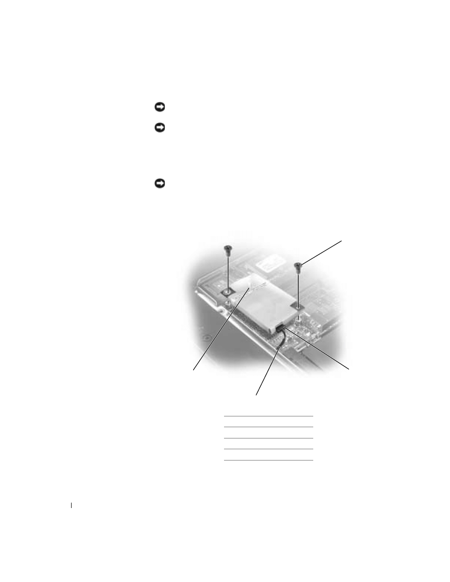
2
Remove the two M2 x 3-mm screws that secure the modem to the
system board.
NOTICE: Do not pull on the modem cable. Pull from the modem connector to
disconnect the cable.
3
Pull straight up on the attached pull-tab to lift the modem out of its
connector on the system board and disconnect the modem cable.
1 M2 x 3-mm screws (2)
2 modem connector
3 modem cable
4 pull-tab
2
3
1
4

23
Replacing the Modem
1
Connect the modem cable to the modem.
NOTICE: The connectors are keyed for correct insertion; do not force the
connections.
2
Align the modem with the screw holes on the system board and press
down on the pull-tab to seat the modem in the connector.
NOTICE: Pressing down on the modem anywhere other than on the pull-tab
can break the modem.
3
Install the two M2 x 3-mm screws that secure the modem to the
system board.
4
Replace the cover, and tighten the screws.

24
www
.dell.com | support.dell.com
25
Keyboard
Removing the Keyboard
NOTICE: Disconnect the computer and any attached devices from electrical
outlets, and remove any installed batteries.
NOTICE: To avoid ESD, ground yourself by using a wrist grounding strap or
by touching an unpainted metal surface on the computer.
NOTICE: Read "Preparing to Work Inside the Computer" before performing
the following procedure.
1
Remove the
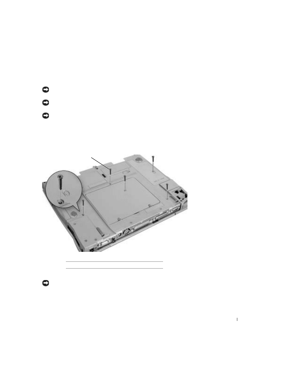
2
Turn the computer over, and remove the five M2.5 x 12-mm screws
labeled "circle K."
3
Turn the computer over and open the display.
NOTICE: The key caps on the keyboard are fragile, easily dislodged, and
time-consuming to replace. Be careful when removing and handling the
keyboard.
1
M2.5 x 12-mm screws (5)
1
26
www
.dell.com | support.dell.com
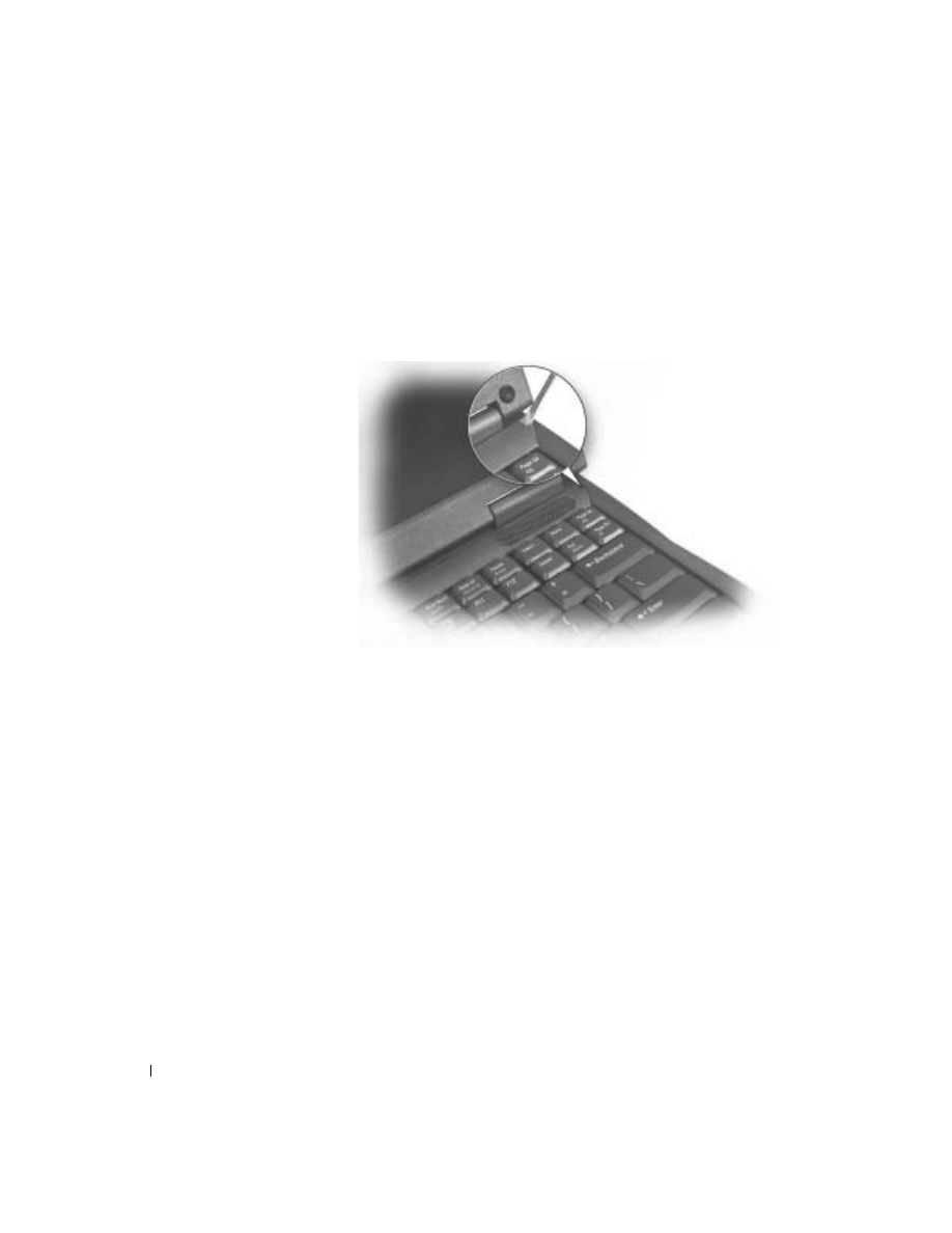
4
Remove the center control cover:
a
Use a small, flat-blade screwdriver or plastic scribe to lift the right
edge of the center control cover and pry it loose from the bottom
case.
b
Lift the center control cover up and away from the bottom case.
5
To release the keyboard from the palm rest, use a small, flat-blade
screwdriver or plastic scribe to pull up on the right edge of the blank
key on the keyboard.
27
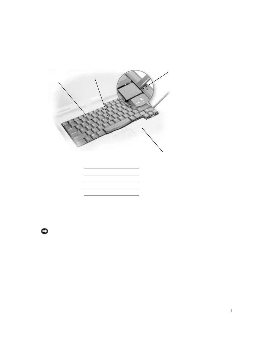
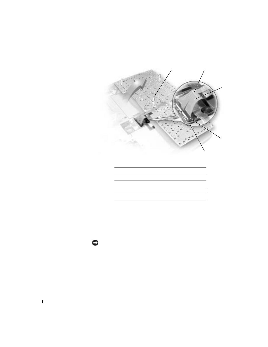
6
Lift the keyboard straight up until it clears the keyboard boss support
in the bottom case.
7
Rotate the keyboard forward toward the front of the computer.
8
Rest the key face of the keyboard on the palm rest.
NOTICE: Do not pull on the keyboard flex and track stick cables.
9
Pull up on the keyboard connector to disconnect it from the interface
connector on the system board.
1 keyboard
2 track stick
3 blank key
4 palm rest
1
3
2
4
28
www
.dell.com | support.dell.com
10
Remove the keyboard from the bottom case.
Replacing the Keyboard
1
Place the keyboard on the palm rest at the front of the computer with
the keys face down and the connector toward the back of the
computer.
NOTICE: To avoid damage to the connector pins, press the keyboard
connector evenly into the interface connector on the system board, and do not
reverse the keyboard connector.
2
Connect the keyboard connector to the interface connector on the
system board.
1
boss support (5)
2
track stick cable
3
keyboard flex cable
4
keyboard connector
5
orientation label
2
3
4
5
1

29
The keyboard connector may have a label on it that shows the correct
orientation of the keyboard connector to the system-board interface
connector.
3
Carefully turn the keyboard over. Align the keyboard boss support, fit
the left side of the keyboard into place, and then snap the right side of
the keyboard into place.
NOTICE: Position the keyboard flex and track stick cables so that they are
not pinched when you replace the keyboard in the bottom case.
4
Check that the keyboard is correctly installed. The keys should be flush
with the left and right surfaces of the palm rest.
5
Replace the center control cover, close the display assembly, and turn
the computer over.
6
Reinstall the five M2.5 x 12-mm screws in the holes labeled “circle K.”

30
www
.dell.com | support.dell.com
31
Display, Display Assembly, Display
Latch, and Hinge Covers
Display
NOTICE: You must remove the display before you remove the palm rest.
NOTICE: Disconnect the computer and any attached devices from electrical
outlets, and remove any installed batteries.
NOTICE: To avoid ESD, ground yourself by using a wrist grounding strap or
by touching an unpainted metal surface on the computer.
NOTICE: Read "Preparing to Work Inside the Computer" before performing
the following procedure.
5
3
6
2
1
4

32
www
.dell.com | support.dell.com
1
Remove the
2
Remove the
3
Remove the
.
4
Close the display.
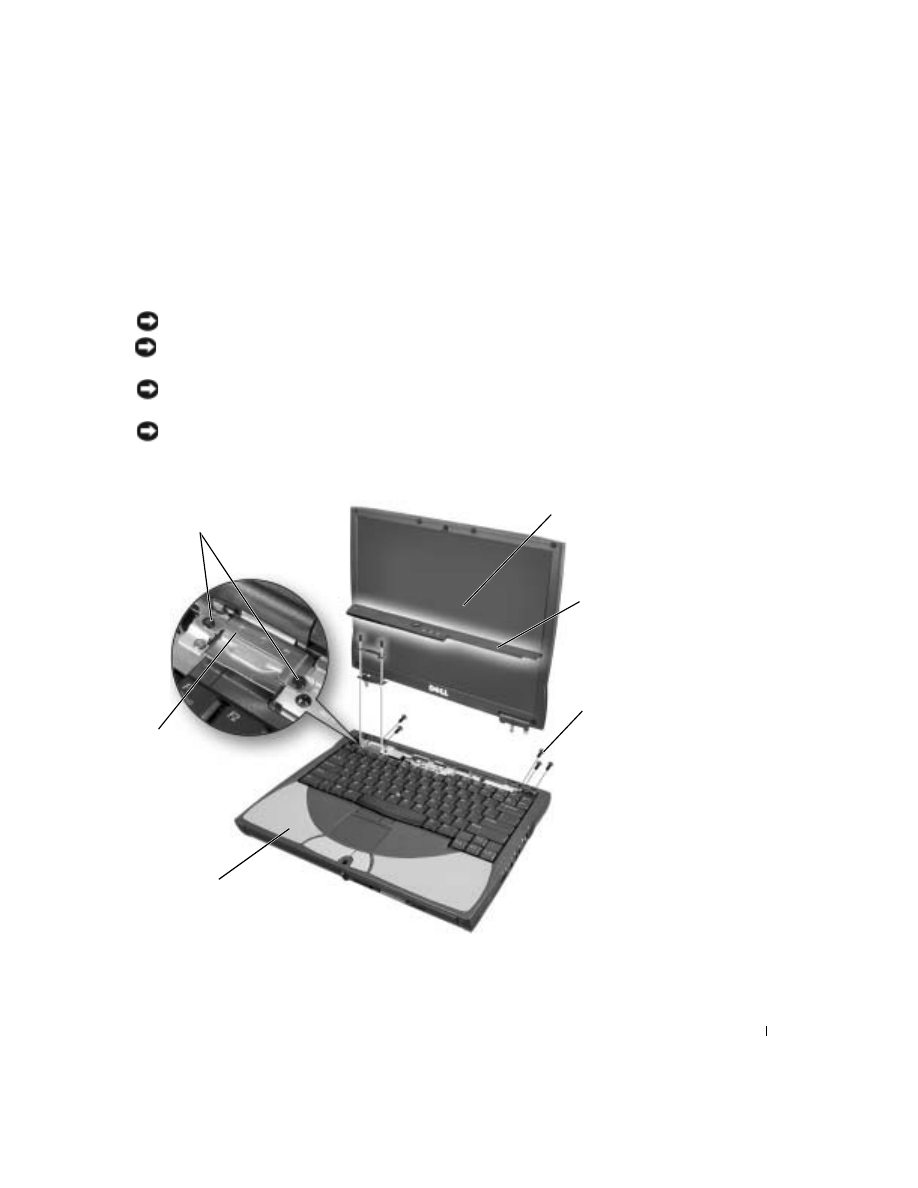
5
From the back of the computer, remove the five M2.5 x 5-mm screws
labeled "circle D."
6
Open the display approximately 180 degrees and support the display so
that it does not open past this position.
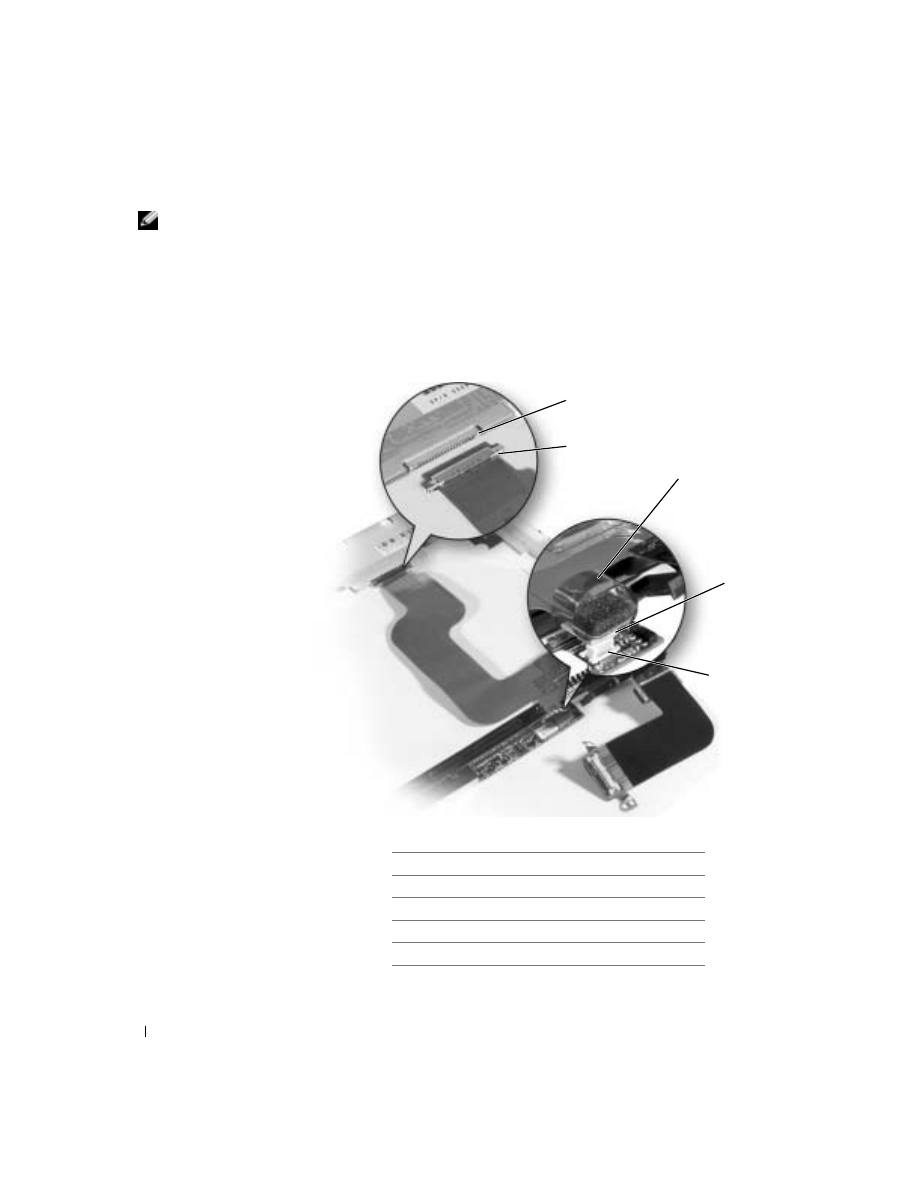
7
Remove the two M2 x 3-mm screws on the EMI shield bracket, which
is attached to the display-feed flex cable.
8
Remove the two M2 x 3-mm screws that secure the display-feed flex
cable to the system board.
NOTICE: When reconnecting the display-feed flex cable connector to the
system board, push down on the top-left and top-right ends of the connector.
Pressing on the center of the connector may damage resistors and compromise
EMI protection in the computer.
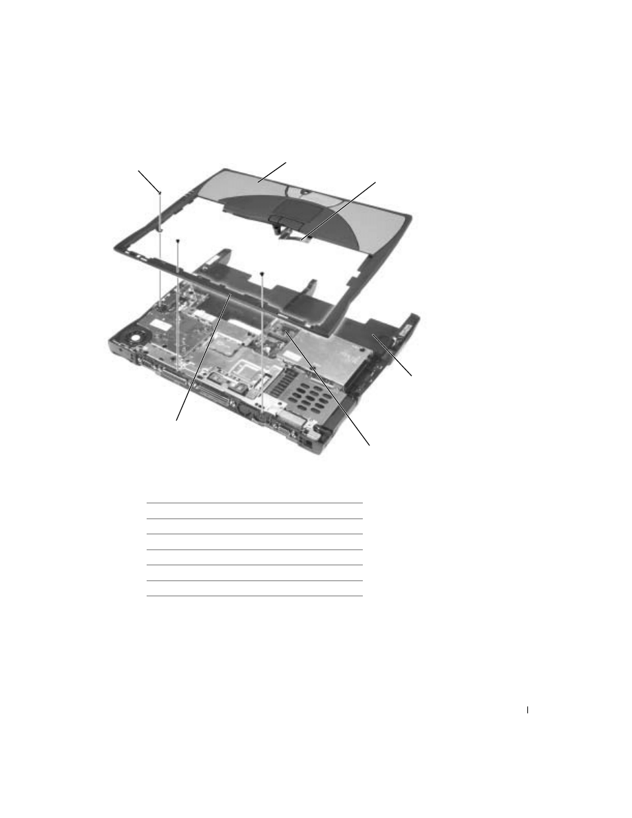
1
M2 x 3-mm screws (4)
2
top cover
3
center control cover
4
M2.5 x 5-mm screws (5)
5
bottom case
6
EMI shield bracket
33
9
Pull up on the pull-tab that is attached to the display-feed flex cable
connector to remove the tab from the interface connector on the
system board.
10
Pivot the display up to a 90-degree angle, and lift it up and out of the
bottom case.
1
M2 x 3-mm screws (2)
1
34
www
.dell.com | support.dell.com
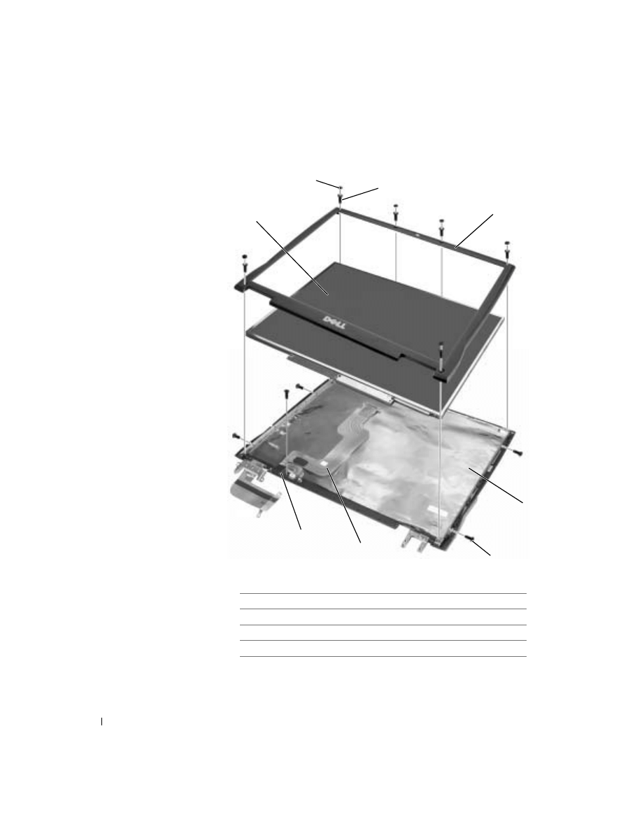
Display Assembly
1
rubber screw covers (4)
5
M2 x 4-mm screws (5)
2
M2.5 x 5-mm screws (4)
6
display-feed flex cable
3
display bezel
7
flex-cable retention bracket
4
top cover
8
display panel
7
3
8
1
2
4
5
6

35
Removing the Display Bezel
NOTICE: Disconnect the computer and any attached devices from electrical
outlets, and remove any installed batteries.
NOTICE: To avoid ESD, ground yourself by using a wrist grounding strap or
by touching an unpainted metal surface on the computer.
NOTICE: Read "Preparing to Work Inside the Computer" before performing
the following procedure.
1
Remove the
2
Remove the
3
Use a plastic scribe to pry the four rubber screw covers out of the screw
holes located on the front of the bezel.
4
Remove the four M2.5 x 5-mm screws located on the front of the
bezel.
NOTICE: Carefully separate the bezel from the top cover to avoid damage to
the bezel.
5
Starting at the bottom of the display panel (by the DELL™ logo), use
your fingers to separate the bezel from the top cover by lifting up the
inside of the bezel while pushing in on the outside.
Removing the Display Panel
NOTICE: Disconnect the computer and any attached devices from electrical
outlets, and remove any installed batteries.
NOTICE: To avoid ESD, ground yourself by using a wrist grounding strap or
by touching an unpainted metal surface on the computer.
NOTICE: Read "Preparing to Work Inside the Computer" before performing
the following procedure.
1
Remove the
2
Remove the
3
Remove the
4
Remove the
5
Remove the two M2 x 4-mm screws on the left side of the display
panel and the two M2 x 4-mm screws on the right side of the display
panel.
36
www
.dell.com | support.dell.com
HINT: If you have a
Hitachi display panel,
remove the two M2 x 4-
mm screws from the
center of the left side of
the display panel.
6
Remove the M2 x 4-mm screw that secures the display-feed flex cable
to the display assembly through the black plastic flex-cable retention
bracket.
7
Lift the display panel from the top and rotate the display panel out of
the top cover.
8
Disconnect the bottom flex-cable connector from the inverter
connector by pulling straight up on the attached pull-tab.
1
display panel connector
2
top flex-cable connector
3
pull-tab
4
bottom flex-cable connector
5
inverter connector
1
2
3
4
5

37
9
Remove the tape that secures the display panel connector and the tape
that secures the middle of the display-feed flex cable to the display
panel.
10
Pull the top flex-cable connector down and away to remove it from the
display panel connector.
Replacing the Display Panel
1
Reconnect the top flex-cable connector to the display panel connector.
2
Reconnect the bottom flex-cable connector to the inverter connector.
3
Replace the tape that secures the display panel connector and the tape
that secures the middle of the display-feed flex cable to the display
panel.
4
Place the bottom edge of the display panel in the bottom of the top
cover and elevate the top of the panel with your hand.
5
Lay the display panel in the top cover.
6
Reinstall the five M2 x 4-mm screws that secure the display panel to
the top cover.
Display Latch
NOTICE: Disconnect the computer and any attached devices from electrical
outlets, and remove any installed batteries.
NOTICE: To avoid ESD, ground yourself by using a wrist grounding strap or
by touching an unpainted metal surface on the computer.
Removing the Display Latch
1
Remove the
2
Remove the
3
Remove the
4
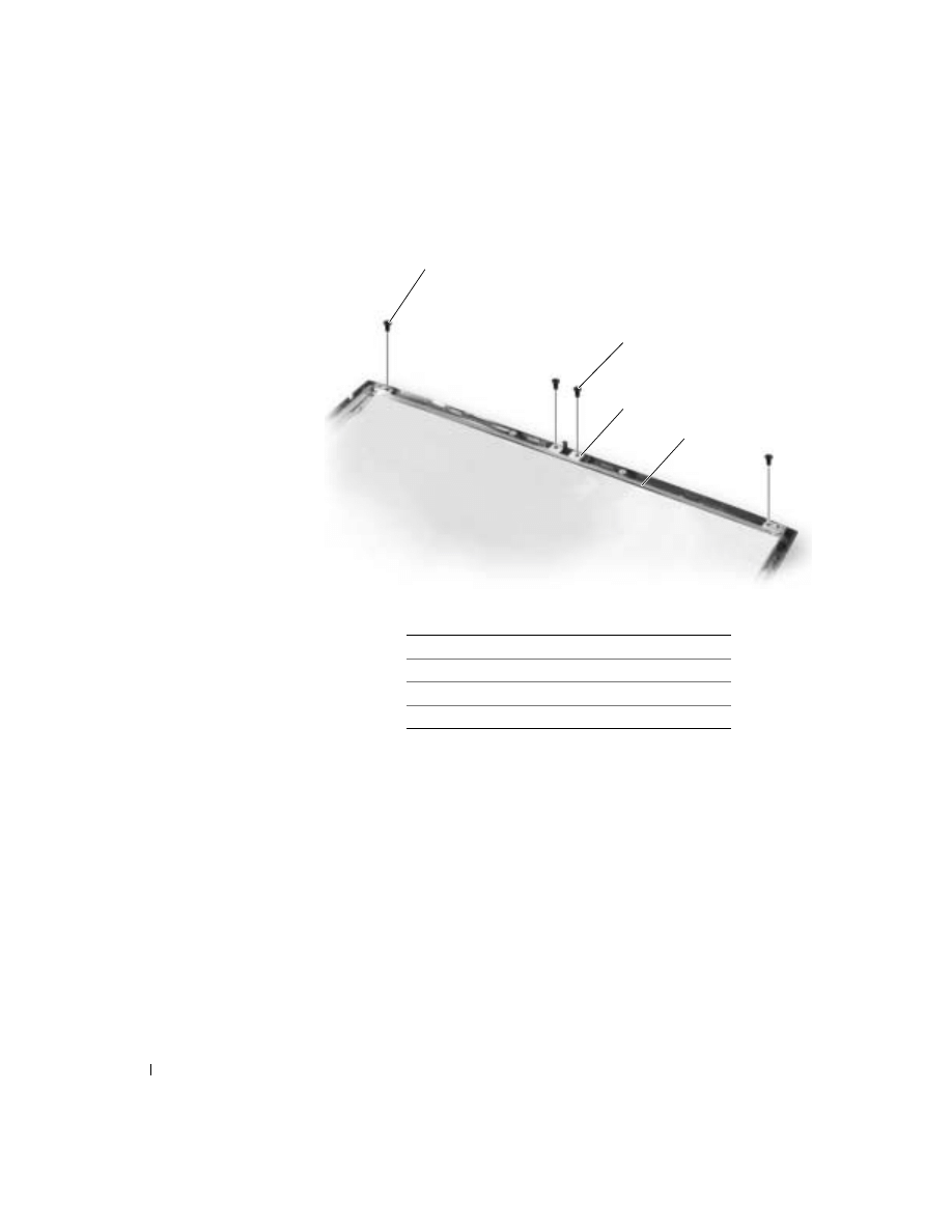
Remove the two M2.5 x 5-mm screws and the two M1.7 x 3.5-mm
screws that secure the display latch and bracket to the top cover.
5
Lift the display latch and bracket up and out of the top cover.
38
www
.dell.com | support.dell.com
( X G A p a n e l s h o w n )
Replacing the Display Latch
1
On XGA panels, place the display latch on top of its screw holes, and
then place the bracket on top of the display latch, aligning the bracket
and display latch screw holes.
On SXGA+ and UXGA panels, align the screw holes and place the
display latch and attached bracket in the top cover.
2
Replace the two M2.5 x 5-mm screws and the two M1.7 x 3.5-mm
screws that secure the display latch and bracket to the top cover.
1
M1.7 x 3.5-mm screws (2)
2
M2.5 x 5-mm screws (2)
3
display latch
4
bracket
2
1
4
3
39
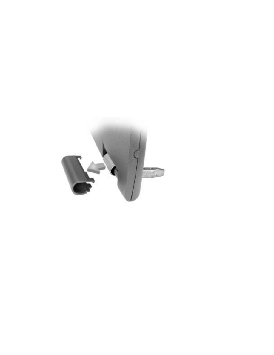
Hinge Covers
Removing the Hinge Covers
1
Remove the
2
Rotate the hinges forward at an angle of approximately 90 degrees to
the front of the display.
3
To remove the hinge covers, slide them off the hinges.
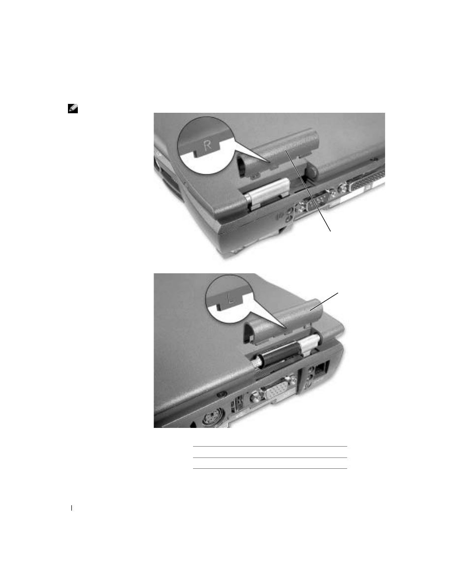
Replacing the Hinge Covers
1
Attach the display to the bottom case.
2
Close the display.
3
Snap the hinge covers in place over the hinges.
40
www
.dell.com | support.dell.com
HINT: The right
plastic hinge-cover label
includes an "R," and the
left plastic hinge-cover
label includes an "L." The
hinge-cover labels face the
back of the computer.
1
right hinge cover
2
left hinge cover
1
2
41
Palm Rest
NOTICE: Disconnect the computer and any attached devices from electrical
outlets, and remove any installed batteries.
NOTICE: To avoid ESD, ground yourself by using a wrist grounding strap or
by touching an unpainted metal surface on the computer.
NOTICE: Read "Preparing to Work Inside the Computer" before performing
the following procedure.
1
Remove the
2
Remove the
NOTICE: You must remove the display before you remove the palm rest; the
display hinges pass through the back of the palm rest.
3
Remove the
.
4
Turn the computer over and remove the three M2.5 x 12-mm screws
labeled "circle P."
1
2
3

42
www
.dell.com | support.dell.com
5
Remove the two M2 x 3-mm screws that are located in the hard drive
door labeled "circle P."
6
Turn the computer over, and remove the three M2 x 3-mm screws that
secure the palm rest to the bottom case:
a
Remove the two M2 x 3-mm screws that are located on the back
edge of the bottom case, underneath the display.
b
Remove the M2 x 3-mm screw located underneath the keyboard,
on the right side of the bottom case, next to the microprocessor
thermal cooling assembly and opposite the S-video TV-out
connector.
7
Pull up on the pull-tab that is attached to the palm-rest flex cable
connector to remove it from the interface connector on the system
board.
1
M2.5 x 12-mm screws (3)
2
M2 x 3-mm screws (2)
3
hard drive door
43
1
M2 x 3-mm screws (3)
2
palm rest
3
palm-rest flex cable
4
bottom case
5
touch pad connector
6
back center of the palm rest
2
5
4
3
1
6

44
www
.dell.com | support.dell.com
NOTICE: Carefully separate the palm rest from the bottom case to avoid
damage to the palm rest.
8
Starting at the back center of the palm rest, use your fingers to
separate the palm rest from the bottom case by lifting the inside of the
palm rest while pushing in on the outside.
45
Microprocessor Thermal Cooling
Assembly
Removing the Microprocessor Thermal Cooling Assembly
NOTICE: Disconnect the computer and any attached devices from electrical
outlets, and remove any installed batteries.
NOTICE: To avoid ESD, ground yourself by using a wrist grounding strap or
by touching an unpainted metal surface on the computer.
NOTICE: Read "Preparing to Work Inside the Computer" before performing
the following procedure.
1
Remove the
2
Remove the
3
Loosen the four captive screws that secure the microprocessor thermal
cooling assembly to the system board.
2
1
4
3

46
www
.dell.com | support.dell.com
4
Insert a screwdriver into the recess in the EMI shield under the front-
left corner of the thermal cooling assembly, and pry the assembly up
and away from the system board.
Replacing the Microprocessor Thermal Cooling Assembly
NOTICE: When replacing the microprocessor, to ensure proper thermal
operation, always install a new thermal cooling assembly that is compatible
with the new microprocessor.
1
Place the right side of the microprocessor thermal cooling assembly
under the palm rest, and lower the assembly onto the system board.
2
Tighten the four captive screws, labeled "1" through "4," in consecutive
order.
1
microprocessor thermal cooling assembly
2
captive screws (4)
3
right side of the thermal cooling assembly
4
recess in the EMI shield (prying location)

47
Microprocessor
Microprocessor Module
Removing the Microprocessor Module
NOTICE: Disconnect the computer and any attached devices from electrical
outlets, and remove any installed batteries.
NOTICE: To avoid ESD, ground yourself by using a wrist grounding strap or
by touching an unpainted metal surface on the computer.
NOTICE: Read "Preparing to Work Inside the Computer" before performing
the following procedure.
NOTICE: When replacing the microprocessor, to ensure proper thermal
operation, always install a new thermal cooling assembly that is compatible
with the new microprocessor.
NOTICE: Do not touch the processor die. Press and hold the microprocessor
down on the substrate on which the die is mounted while turning the cam screw
to prevent intermittent contact between the cam screw and microprocessor.
NOTICE: To avoid damage to the microprocessor, hold the screwdriver so that
it is perpendicular to the microprocessor when turning the cam screw.
48
www
.dell.com | support.dell.com
1
Remove the
2
Remove the
.
NOTICE: To ensure maximum cooling for the microprocessor, do not touch
the heat transfer areas on the microprocessor thermal cooling assembly. The
oils in your skin reduce the heat transfer capability of the thermal pads.
3
Remove the
microprocessor thermal cooling assembly
NOTICE: When removing the microprocessor module, pull the module
straight up. Be careful not to bend the pins on the microprocessor module.
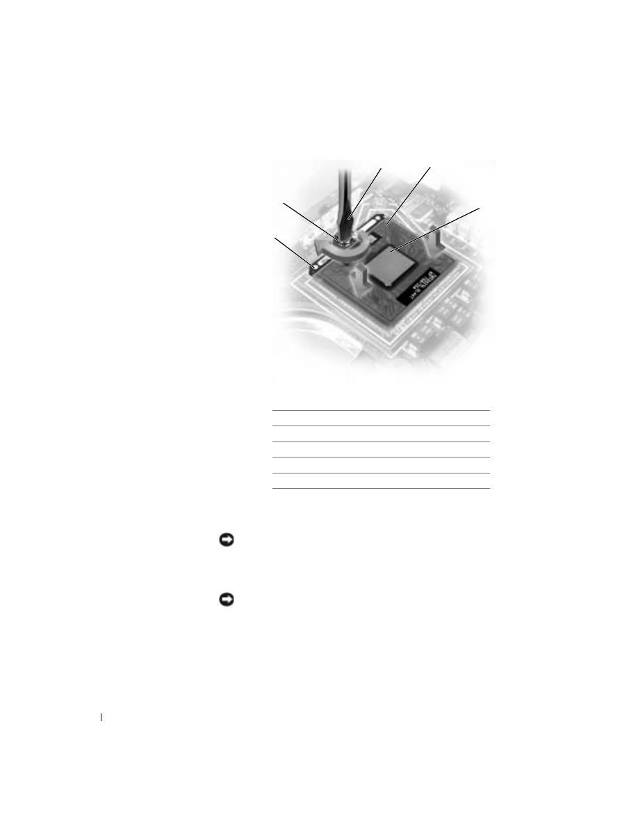
4
To loosen the ZIF socket, use a small, flat-blade screwdriver and rotate
the ZIF-socket cam screw counterclockwise until it comes to the cam
stop.
1
screwdriver (perpendicular to microprocessor)
2
pin-1 corner
3
processor die (do not touch)
4
ZIF socket
5
ZIF-socket cam screw
5
2
4
lock
1
3

49
The ZIF-socket cam screw secures the microprocessor to the system
board. Take note of the arrow on the ZIF-socket cam screw.
5
Use a microprocessor extraction tool to remove the microprocessor
module.
Replacing the Microprocessor Module
NOTICE: Ensure that the cam lock is in the fully open position before seating
the microprocessor module. Seating the microprocessor module properly in the
ZIF socket does not require force.
NOTICE: A microprocessor module that is not properly seated can result in
an intermittent connection or permanent damage to the microprocessor and
ZIF socket.
1
Align the pin-1 corner of the microprocessor module with the pin-1
corner of the ZIF socket, and insert the microprocessor module.
HINT: The pin-1
corner of the
microprocessor module
has a triangle that aligns
with the triangle on the
pin-1 corner of the ZIF
socket.
NOTICE: You must position the microprocessor module correctly in the ZIF
socket to avoid permanent damage to the module and the socket.
When the microprocessor module is correctly seated, all four corners
are aligned at the same height. If one or more corners of the module
are higher than the others, the module is not seated correctly.
NOTICE: Hold the microprocessor down while turning the cam screw to
prevent intermittent contact between the cam screw and microprocessor (see
"
Removing the Microprocessor Module
2
Tighten the ZIF socket by turning the cam screw clockwise to secure
the microprocessor module to the system board.
NOTICE: When replacing the microprocessor, to ensure proper thermal
operation, always install a new thermal cooling assembly that is compatible
with the new microprocessor.
3
Install a new
microprocessor thermal cooling assembly
4
using a flash BIOS update program CD.
Flashing the BIOS
To update the BIOS:
1
Ensure that the AC adapter is plugged into an electrical outlet and
that the main battery is installed in the battery bay.

50
www
.dell.com | support.dell.com
2
Turn on the computer, and when the Dell™ logo appears, press
immediately.
If you wait too long and the Windows
®
logo appears, continue to wait
until you see the Windows desktop. Then shut down your computer
and try again.
3
When the boot device list appears, highlight CD/DVD/CD-RW drive
and press
.
4
Insert the flash BIOS update CD, and reboot the computer.
The computer boots, updates the BIOS, and reboots.
5
Remove the flash BIOS update CD.
51
Hybrid Cooling Fan
Removing the Hybrid Cooling Fan
NOTICE: Disconnect the computer and any attached devices from electrical
outlets, and remove any installed batteries.
NOTICE: To avoid ESD, ground yourself by using a wrist grounding strap or
by touching an unpainted metal surface on the computer.
NOTICE: Read “Preparing to Work Inside the Computer” before performing
the following procedure.
1
Remove the
2
Remove the
3
Remove the
4
Remove the
.
5
Remove the
microprocessor thermal cooling assembly
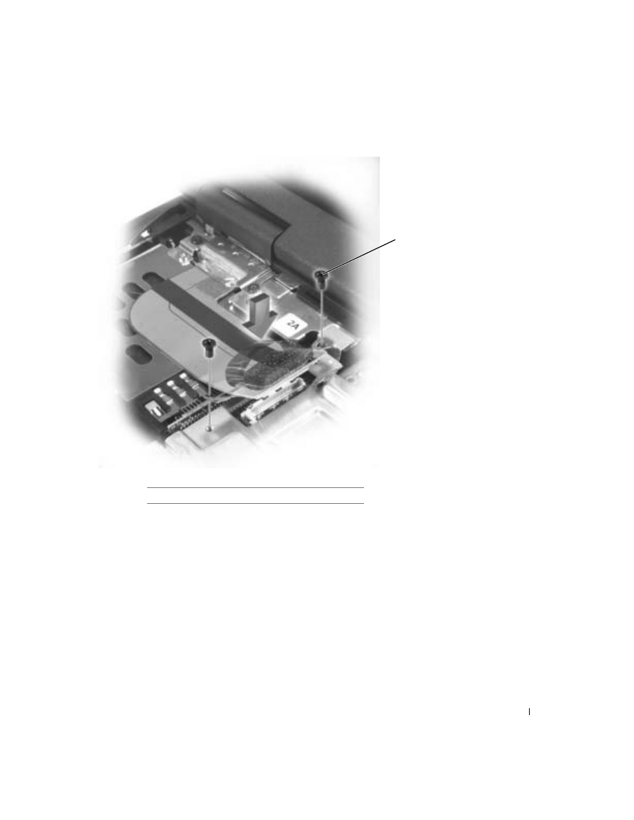
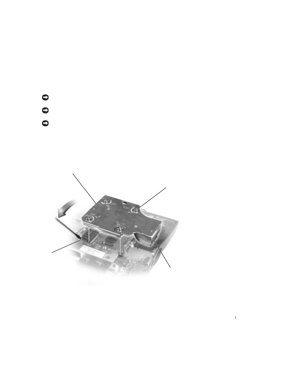
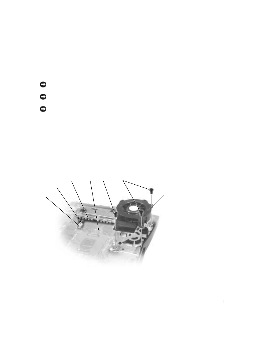
6
Remove the two M2.5 x 5-mm screws and one M2 x 3-mm screw that
secure the hybrid cooling fan to the system board.
6
7
5
1
4
3
2

52
www
.dell.com | support.dell.com
7
Disconnect the fan power cable from the system-board interface
connector and remove the hybrid cooling fan.
HINT: The fan power
cable is long, and can be
pulled out from under the
EMI shield to provide
access to the connector.
NOTICE: Do not block the keyboard screw hole when reinstalling the fan.
Route the fan power cable under the spring fingers and behind the keyboard
screw hole to prevent damage to the fan power cable.
1 system-board interface
connector
5
M2 x 3-mm screw (1)
2 fan power cable
6
M2.5 x 5-mm screws (2)
3 spring fingers
7
hybrid cooling fan
4 keyboard screw hole

53
Reserve Battery
Removing the Reserve Battery
NOTICE: The reserve battery provides power to the computer’s RTC and
NVRAM when the computer is turned off. Removing the battery causes the
computer to lose the date and time information as well as all user-specified
parameters in the BIOS. If possible, make a copy of this information before
you remove the reserve battery.
NOTICE: Disconnect the computer and any attached devices from electrical
outlets, and remove any installed batteries.
NOTICE: To avoid ESD, ground yourself by using a wrist grounding strap or
by touching an unpainted metal surface on the computer.
NOTICE: Read "Preparing to Work Inside the Computer" before performing
the following procedure.
1
Remove the
2
Remove the
3
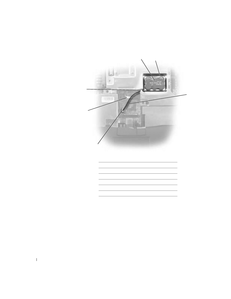
Disconnect the reserve battery cable from the system board connector.
4
Pry the reserve battery free from the system board. The reserve battery
is attached to the system board with a piece of adhesive tape.
5
Remove any remnants of the adhesive tape from the EMI shield.
54
www
.dell.com | support.dell.com
Replacing the Reserve Battery
1
Connect the reserve battery cable to the system board connector, and
then route the battery cable through the opening in the EMI shield to
the battery tray.
2
Remove the backing from the adhesive on the bottom of the reserve
battery, and press the battery into place in the battery tray.
3
using the flash BIOS update program CD.
1
reserve battery
2
reserve battery tray
3
reserve battery cable
4
reserve battery connector
5
speaker cable
6
opening for reserve battery cable
1
4
5
3
6
2
55
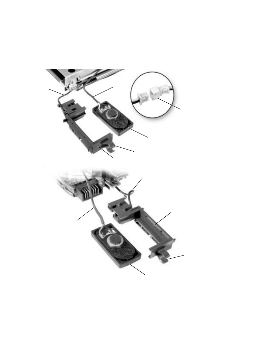
Speakers
Removing the Speaker Assemblies
NOTICE: Disconnect the computer and any attached devices from electrical
outlets, and remove any installed batteries.
NOTICE: To avoid ESD, ground yourself by using a wrist grounding strap or
by touching an unpainted metal surface on the computer.
NOTICE: Read "Preparing to Work Inside the Computer" before performing
the following procedure.
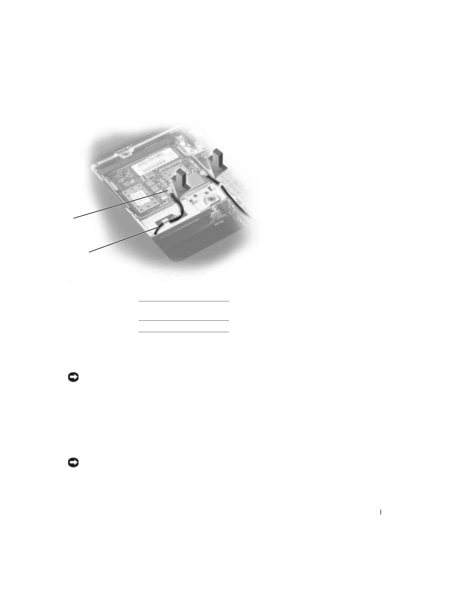
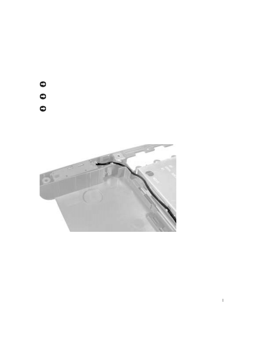
The speakers are located on the front-left and front-right sides of the
bottom case. Take note of the speaker and antenna wire routing so that you
can replace them properly under their routing clips.
56
www
.dell.com | support.dell.com
1
right speaker
2
palm-rest screw post
3
bottom case holders (2)
4
left speaker
4
1
3
2
57
3
4
10
8
6
1
7
5
9
2
11
58
www
.dell.com | support.dell.com
1
Remove the
2
Remove the
.
3
Remove the
4
Remove the
5
Disconnect the speaker interface cable connectors. (Do not attempt to
disconnect the antenna cables.)
NOTICE: Do not pull the antenna wire when removing the speaker.
NOTICE: Handle the speaker assemblies and speakers with care to avoid
damaging the speaker cones.
6
Remove the speaker assemblies by pulling them straight up and out of
the bottom case.
7
Remove the speakers from the holders by sliding the speakers out the
bottom of the holders.
HINT: The left speaker
has an in-line connector,
and its antenna cable is
longer than the antenna
cable of the right speaker.
Replacing the Speaker Assemblies
1
Slide the new speaker into its holder so that the speaker faces outward
(toward the speaker grill on the side of the computer) when the
speaker assembly is installed.
2
Place the mounting ring over the front palm-rest screw post.
NOTICE: Ensure that the speaker wires are routed securely under their
mounting clips.
3
Slide the speaker assembly down into the bottom case.
1
antenna cable
7
antenna cable
2
speaker interface cable
8
right speaker holder
3
in-line connector
9
mounting ring
4
left speaker
10
right speaker
5
mounting ring
11
speaker interface cable
6
left speaker holder

59
System Board
Removing the System Board
The system board’s BIOS chip contains the service tag sequence, which is
also visible on a barcode label on the bottom of the computer. The
replacement kit for the system board includes a CD that provides a utility
for transferring the service tag sequence to the replacement system board.
NOTICE: Disconnect the computer and any attached devices from electrical
outlets, and remove any installed batteries.
NOTICE: To avoid ESD, ground yourself by using a wrist grounding strap or
by touching an unpainted metal surface on the computer.
NOTICE: Read "Preparing to Work Inside the Computer" before performing
the following procedure.
1
Remove the
2
Remove the
3
Remove the
4
Remove the
.
5
Remove the
microprocessor thermal cooling assembly
6
Remove the
7
Remove the
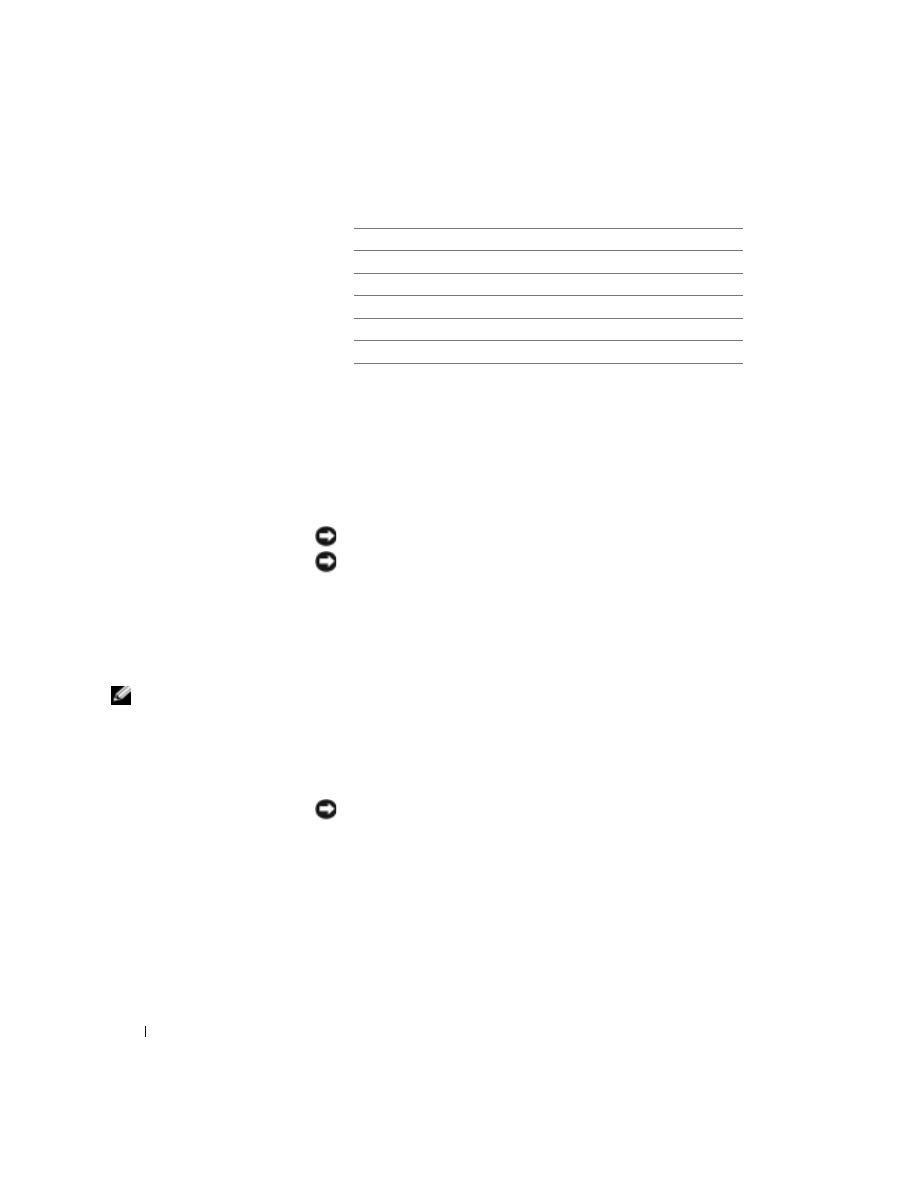
8
From the bottom of the computer, remove the six M2.5 x 5-mm screws
labeled "circle B" that secure the system board to the bottom case.
9
Remove the three M2.5 x 5-mm screws labeled “circle B” that secure
the fan guard to the bottom case.
60
www
.dell.com | support.dell.com
10
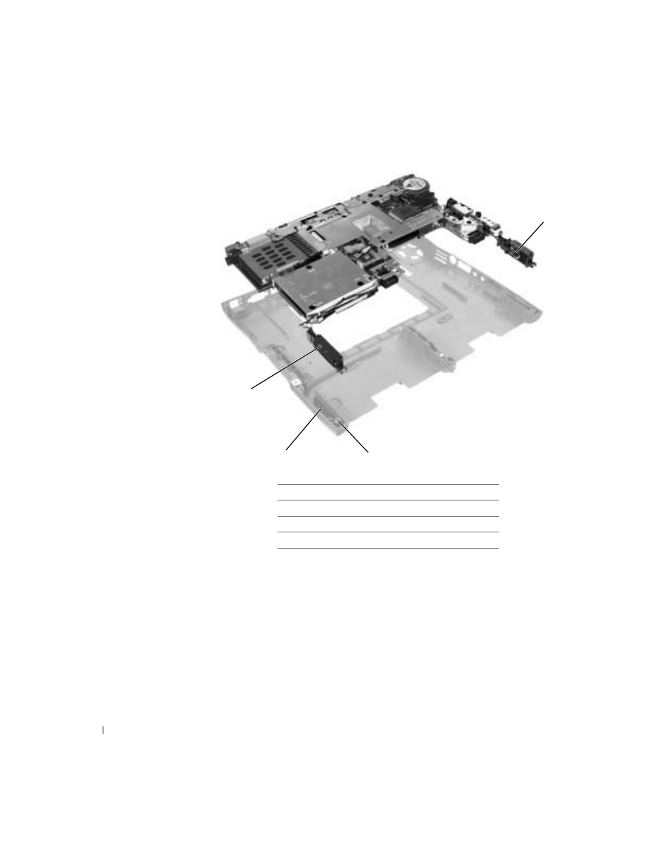
Turn the computer over and remove the M2.5 x 5-mm screw, which is
labeled "circle B" with an arrow, by the battery connector on the front
center of the system board.
1
fan guard
2
M2.5 x 5-mm screws (9)
2
1
61
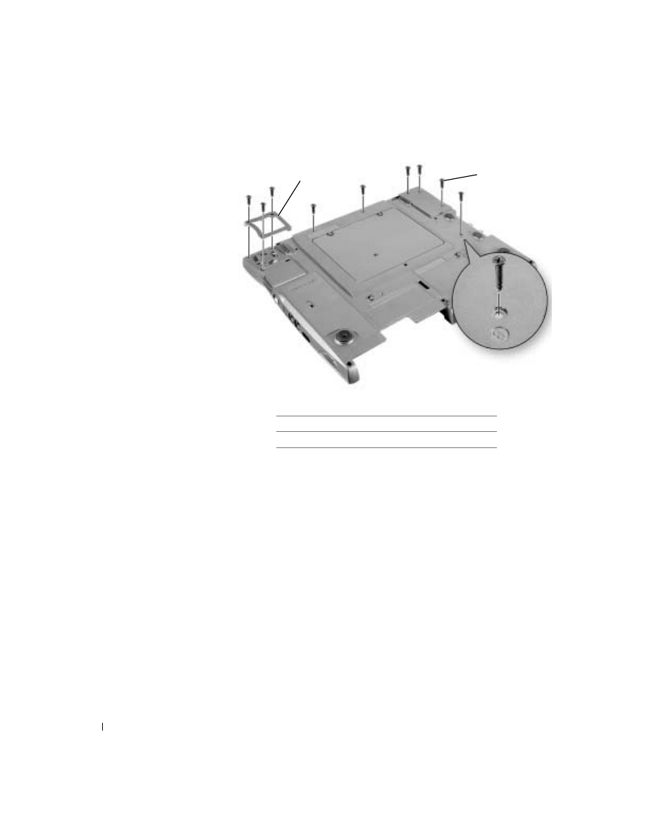
11
Remove the
from the bottom case.
12
Pull the right side of the bottom case, next to the external headphone
and microphone connectors, away from the system board as you
simultaneously lift the front of the system board out and away from
the bottom case.
Replacing the System Board
1
Install the
on the replacement system board.
2
Install the replacement system board:
a
Insert the external microphone and headphone connectors
through the bottom case.
1
M2.5 x. 5-mm screw (1)
1

62
www
.dell.com | support.dell.com
b
Replace the six M2.5 x 5-mm screws, starting on the right side of
the bottom case.
c
Replace the fan guard, inserting the tab into the bottom case, and
replace the three M2.5 x 5-mm screws. Replacing the screw
opposite the tab first makes it easier to insert and replace the other
two screws.
3
Install the modem and the microprocessor thermal cooling assembly
that you removed from the old system board.
HINT: Route cables
so that they are not
crimped or pinched when
the complete assembly is
put back together.
4
Connect the right and left
system board in the bottom case.
5
Replace the palm rest, the keyboard, the display, and the hard drive.
6
Replace the module bay devices and any PC Cards or plastic blanks in
the PC Card slot.
7
Insert the CD that accompanied the replacement system board into
the drive, and turn on the computer. Follow the instructions on the
screen.
HINT: After
installing the system
board, enter the computer
service tag sequence into
the BIOS of the
replacement system
board.

63
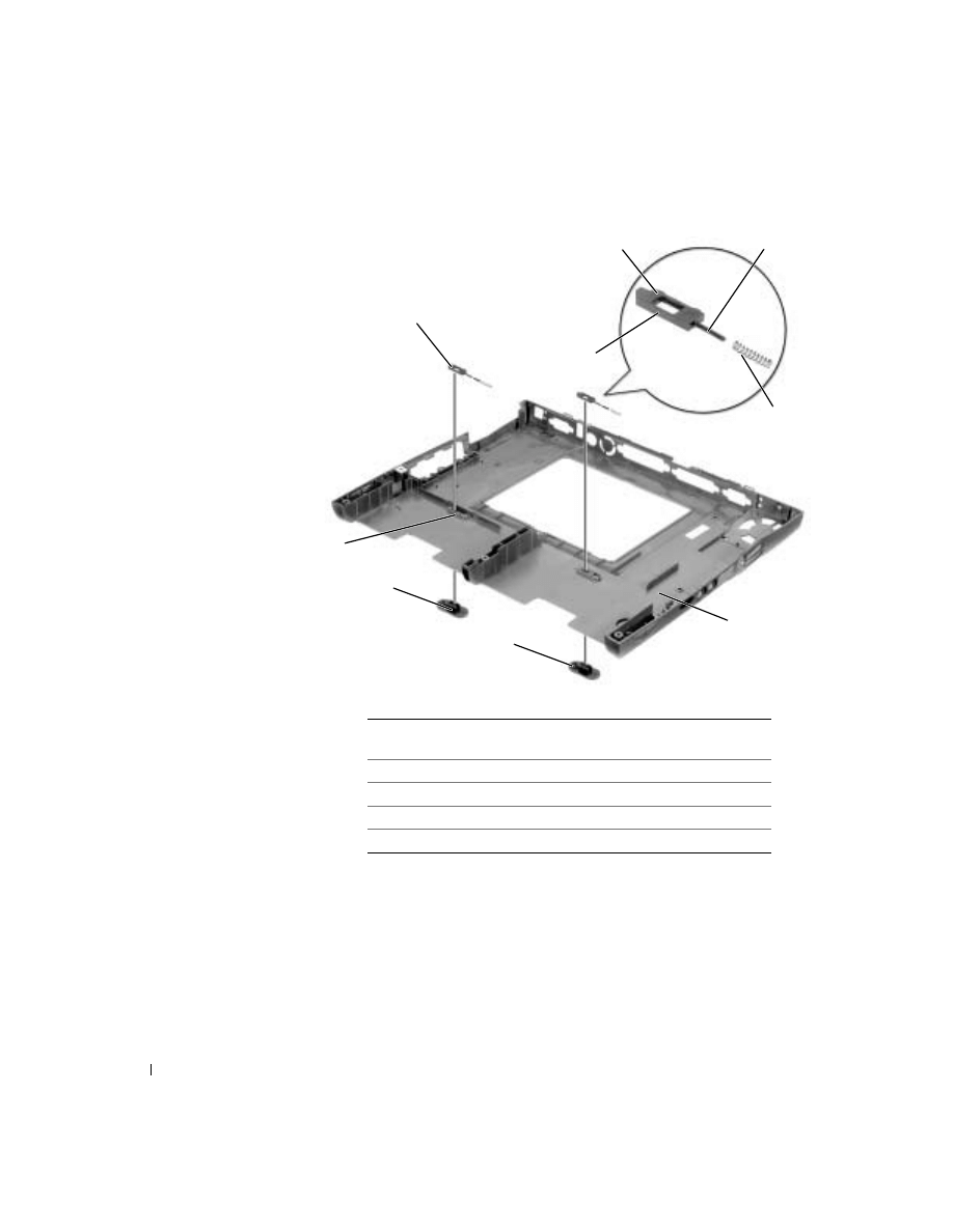
Battery and Module Bay Latches
Removing the Battery and Module Bay Latches
NOTICE: Disconnect the computer and any attached devices from electrical
outlets, and remove any installed batteries.
NOTICE: To avoid ESD, ground yourself by using a wrist grounding strap or
by touching an unpainted metal surface on the computer.
NOTICE: Read "Preparing to Work Inside the Computer" before performing
the following procedure.
1
Remove the
2
Remove the
3
Remove the
4
.
5
Remove the
.
6
Remove the latch button by using a plastic scribe to push on the snap
tabs until the latch button is released from the bottom case.
To prevent the latch assembly from coming loose, apply pressure to the
latch and spring while removing the latch button.
64
www
.dell.com | support.dell.com
Replacing the Battery and Module Bay Latches
1
If you are replacing the upper latch assembly:
a
Slide the spring onto the slider, and reinstall the latch in the
holding features on the inside of the bottom case.
1
bumps (2 per latch)
6
snap tabs (2 per latch
button)
2
slider
7
holding feature (2)
3
spring
8
upper latch assembly (2)
4
bottom case
9
wear rib
5
latch buttons (2)
3
2
5
4
9
1
6
1
8
7

65
b
Ensure that the slider is inserted into the hole, that the side of the
latch with the two bumps is facing the back of the case, and that
the side with the wear rib is facing the front of the case.
HINT: The latch will not
function properly if the
slider is oriented
incorrectly.
2
Snap in the new latch button from behind the bottom case, making
certain that the snap tabs are fully engaged in the latch.
To prevent the latch assembly from coming loose, apply pressure to the
latch and spring while installing the latch button.
3
Ensure that the newly installed latch moves smoothly and freely when
pushed and released.
Document Outline
- Before You Remove or Replace Parts
- System Components
- Palm Rest and Display Cover Inserts
- Hard Drive
- Memory Modules, Mini PCI Card, and Modem
- Keyboard
- Display, Display Assembly, Display Latch, and Hinge Covers
- Palm Rest
- Microprocessor Thermal Cooling Assembly
- Microprocessor
- Hybrid Cooling Fan
- Reserve Battery
- Speakers
- System Board
- Battery and Module Bay Latches
Wyszukiwarka
Podobne podstrony:
Dell Inspiron 1545 charger
Dell Inspiron 17R N7110 QUANTA R03 V03 UMA
Laptop DELL Inspiron 15R i3 370M 2 4GHz 4GB 500GB
Korzystaj z intuicyjnych inspiracji, Rozwój duchowy
Inspiration 2 unit 7
Kulinarne inspiracje Tesco Napoje
Dogmat Niepokalanego Poczęcia inspiracje dla chrześcijańskiej duchowości
InspirujaceHistorie fragment
Inspirowane Raffaello id 214958 Nieznany
4150
Lud i ludowość jako inspiracja i jako temat w lit polskiej, Kultura ludowa
Dramaty Szekspira jako Ľródło inspiracji dla literatury
Psychoterapia behawioralna- źródła i inspiracje.word97, studia, techniki poznawczo behawioralne
4150
Orientalne i okultystyczne inspiracje kursów dla nauczycieli-mandala, EGZORCYZMY
więcej podobnych podstron