28-050
Mechanical
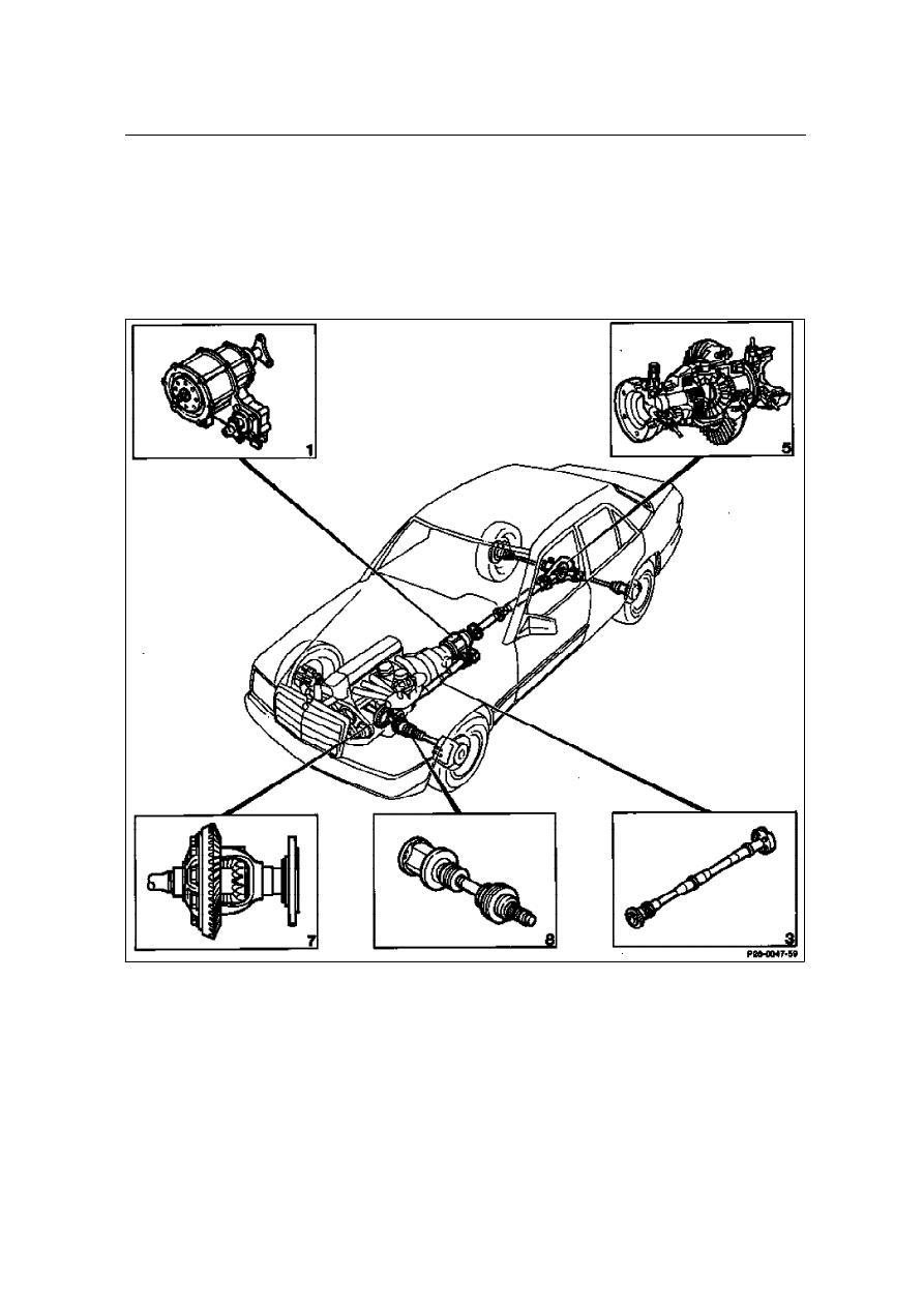
Mechanical components
7
Front axle differential
8
Front axle shaft
1
Transfer case
3
Front-wheel drive propeller shaft
5
Rear axle differential (ASD)
Function of mechanical components
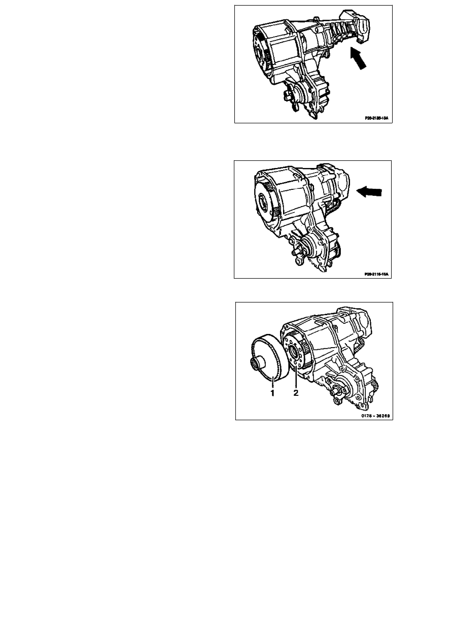
Transfer case
The transfer case distributes the power flow to the
front and rear axle. There are two versions:
For models with manual transmission: transfer case
with long rear cover (arrow).
For models with automatic transmission: transfer
case with short rear cover (arrow).
Note
As of transfer case no. 7 013 a center differential (2)
with modified teeth (straight) has been installed in
the transfer case. At the same time, the manual and
automatic transmissions are fitted with a suitably
modified internally-geared wheel (1).
As of transfer case no. 18 640, an helically geared
planetary gear train (center differential and internally-
geared wheel) has been installed on vehicles with
automatic transmission.
For models 124.333 and 124.393:
Transfer case with short cover and 4-arm joint
flange.
For description of shift processes, refer to section on
power distribution in this chapter.
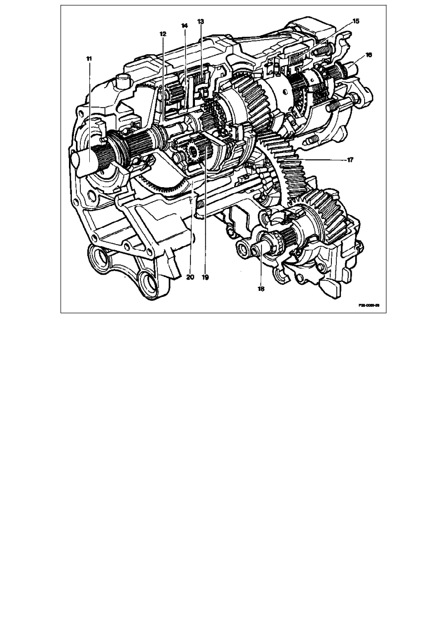
16
Drive shaft - rear axle drive train
17
Auxiliary drive
18
Auxiliary drive shaft - front axle drive train
19
Planet gears - center differential
20
Internal-geared wheel - center differential
11
Transmission output shaft
12
Center differential
13
Multi-disk clutch - center differential lock (ZS)
14
Diaphragm spring
15
Multi-disk clutch - front axle drive train (AV)
Center differential (12)
Drive moment reaches from the transmission
output shaft (11) via toothing to the internal-geared
wheel of the center differential (20). The planetary
gear train of the center differential (12) distributes
the drive moment to the front and rear wheels
depending on the shift condition of the multi-disk
clutches of the center differential lock (ZS) (13)
and front axle drive train (AV) (15).
Multi-disk clutch of center differential lock (ZS)
(13)
The multi-disk clutch of center differential lock (ZS)
(13) brakes the planet carrier of the center
differential (12), so this is directly driven by the
internal-geared wheel. The planet carrier is
connected rigidly to the output shaft of the rear
axle drive train (16).
The multi-disk clutch is held in the closed position
(engaged by friction) by a stiff diaphragm spring
(14). It is released by oil pressure.
Through this design of multi-disk clutch it is
ensured that the vehicle can be driven by rear-
wheel drive even in the event of a fault.
Multi-disk clutch, front axle drive train (AV) (15)
The multi-disk clutch for the front axle drive train
(AV) (15) is closed by oil pressure. In this way the
drive moment is led to the auxiliary drive (17).
Front-wheel drive and oil supply
The transfer case has its own oil supply for
lubrication and heat transfer.
The two gears (lower) for power transmission to
the front-wheel drive also operate as an oil pump.
They supply the oil from the oil pan beneath the
auxiliary drive through an outer oil line on the
transfer case to the bearing points and to lubricate
the multi-disk clutches.
Propeller shaft to front-wheel drive
The propeller shaft connects the transfer case to
the front axle differential.
The length of the propeller shaft differs for manual
and automatic transmission.
It is secured on the transfer case by a flexible disk
and on the front axle differential by a sliding part
for the length differential.
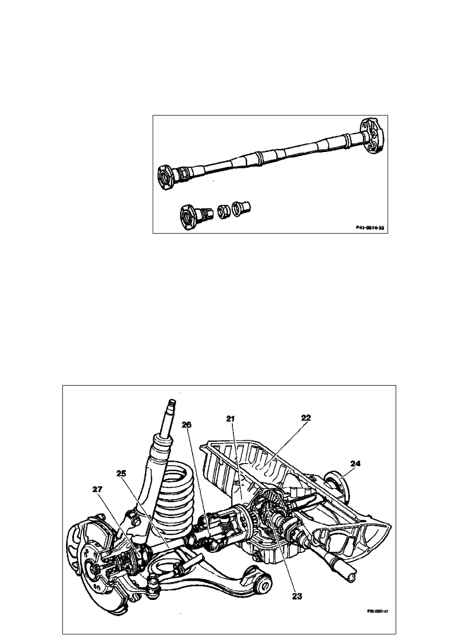
Front-wheel drive
25
Front axle shaft
26
Inner joint
27
Outer joint
21
Front axle casing
22
Engine oil pan
23
Wheel set with differential
24
Connecting flange
The front axle casing (21) and the engine oil pan
(22) form one unit. The front axle casing contains
the gear set with differential (23). The oil
compartments are separated from the differential
and engine. The shaft to the right connecting
flange (24) leads through the engine oil pan and is
partitioned off at this oil compartment by a
protecting tube. The front axle shafts (25) have a
different length on the left and the right. The inner
joint (26) is a sliding joint (tripod joint), which
compensates for axial displacements and angle
changes during
suspension compression. The outer joint (27) is a
rigid joint (Rzeppa joint), which permits steering
lock and jount changes; in addition this joint
secures the front axle shaft in the axial direction.
The damper strut front axle has been retained in
principle. Parts of the wheel control have been
revised for front-wheel drive. Two of the lower coils
on the front springs are fully extended. The front
axle shafts lead to the front wheels through the
resultant space.
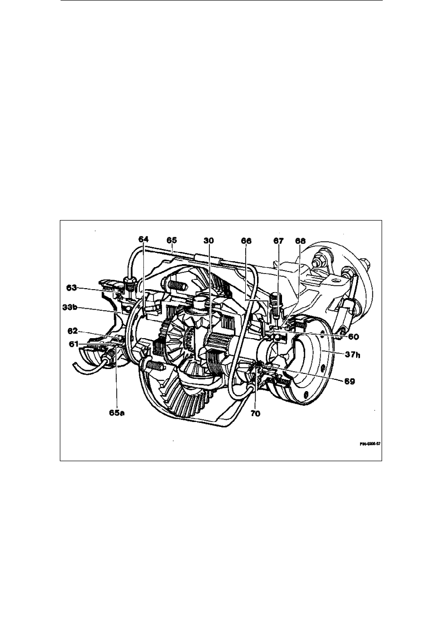
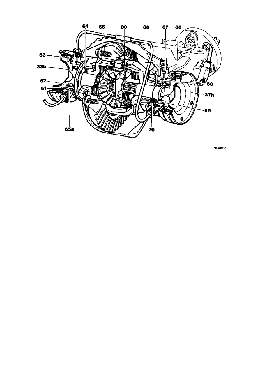
Automatic locking differential of rear axle (ASD)
65
Hydraulic line
65a
Clamping sleeve
66
O-ring (80 x 2)
67
Breather
68
O-ring (72
_
3)
69
Radial sealing ring
70
O-ring (63
_
2,5)
71
Rear axle casing
72
Multi-disk stack
30
Circlip
33b
Connecting flange
37h
Closing plate for H shaft
60
Ring cylinder
61
Annular piston
62
Grooved ball bearing
63
Cup seal
64
Oil baffle

O-rings (66) provide the sealing between the rear
axle casing (71) and ring cylinders (60). The
connecting flanges (33b) are sealed in the ring
cylinders (60) via radial sealing rings (69). The
grooved ball bearings (62) in the annular pistons
(61) are sealed laterally and filled with long-life
lubricant.
To ensure a reliable oil supply to the taper roller
bearings of the differential and the connecting
flange (33b) in the differential, an oil baffle (64) is
installed on each side.
Connecting flange (33b)
The connecting flange (33b) had to be extended
due to accommodating the grooved ball bearing
(62) in the ring cylinder. The grooved ball bearing
is pressed on to the connecting flange (33b).
Rear axle shaft
The rear axle shafts are shorter than on vehicles
without ASD due to the arrangement of the ring
cylinders and connecting flange.
Ring cylinder (60)
The ring cylinders (60) are secured laterally on the
rear axle casing (71) with two M8 hexagon socket
bolts. The annular piston (61) is sealed at the ring
cylinder housing by two O-rings (68 and 70). To
protect against dust and moisture, the annular
piston (61) is protected at the ring cylinder housing
by a pressed-on cup seal (63).
Method of operation of ring cylinders (60):
By applying hydraulic pressure to the annular
piston (61) in the ring cylinders (60), the two
annular pistons (61) move upwards
simultaneously. The resultant force is transmitted
to the differential side gears via the grooved ball
bearing (62), connecting flange (33b) and the
circlips (33) and compresses the multi-disk stack
(72).
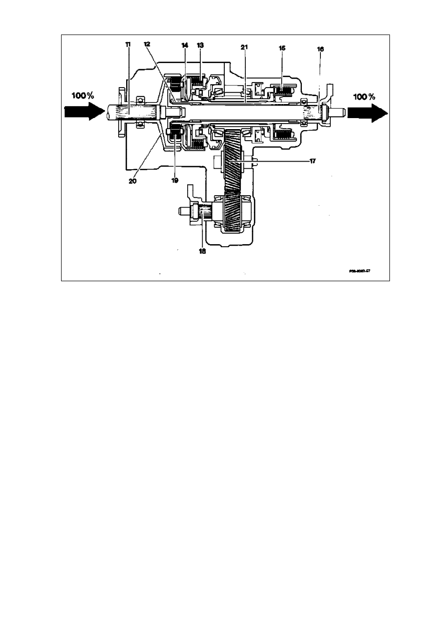
Power flow distribution
Shift stage 0 - rear-wheel drive
16
Output shaft, rear axle drive train
17
Auxiliary drive
18
Auxiliary drive shaft, front axle drive train
19
Planet gears - center differential
20
Internal-geared wheel, center differential
21
Intermediate shaft
11
Transmission output shaft
12
Center differential
13
Multi-disk clutch - center differential lock (ZS)
14
Diaphragm spring
15
Multi-disk clutch - front axle drive train (AV)
The multi-disk clutch of the center differential lock
(ZS) (13) is closed. In this way the planet carrier is
connected to the sun gear and the differential is
locked. The planet gears of the center differential
(19) circulate without differential movement. The
entire drive output is transmitted to the output
shaft of the rear axle drive train (16), to which the
planet carrier is rigidly connected.
The multi-disk clutch of the front axle drive train
(AV) (15) is released, thus the intermediate shaft
(21) connected to the sun gear cannot transmit any
torque to the auxiliary drive shaft of the front axle
drive train (18). A pilot pressure of approx. 1.3 bar
on the multi-disk clutch of the front axle drive train
(AV) (15) ensures a rapid operation when the multi-
disk clutch is engaged.
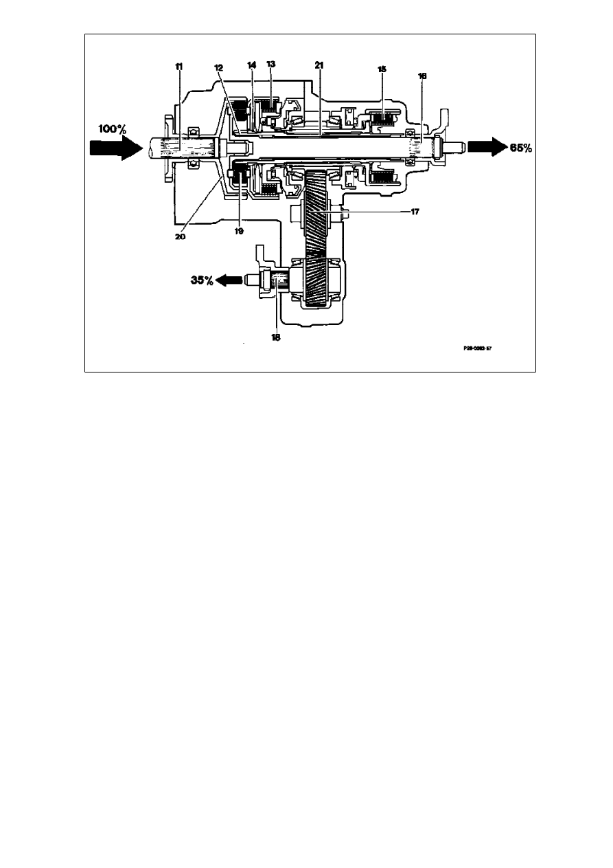
Shift stage 1 - compensated four-wheel drive
16
Output shaft, rear axle drive train
17
Auxiliary drive
18
Auxiliary drive shaft, front axle drive train
19
Planet gears - center differential
20
Internal-geared wheel, center differential
21
Intermediate shaft
11
Transmission output shaft
12
Center differential
13
Multi-disk clutch - center differential lock (ZS)
14
Diaphragm spring
15
Multi-disk clutch - front axle drive train (AV)
The multi-disk clutch of the center differential lock
(ZS) (13) is open. The planet gears of the center
differential (19) are free and can act as a
differential.
The multi-disk clutch of the front axle drive train
(AV) (15) is closed and the drive moment reaches
the auxiliary drive (17) via the intermediate shaft
(21).
The drive moment is branched via the center
differential (12). The ratio is selected so that in the
case of compensated four-wheel drive,
65% of the drive output is transmitted to the rear-
wheel drive and 35% to the front-wheel drive.
To improve driving stability and to prevent the
engine overspeeding when the system engages,
the inter-axle locked condition (shift stage 2) is
engaged briefly by the multi-disk clutch of the front
axle drive train (AV) (15) closing, shortly before the
multi-disk clutch of the center differential lock (ZS)
(13) opens.
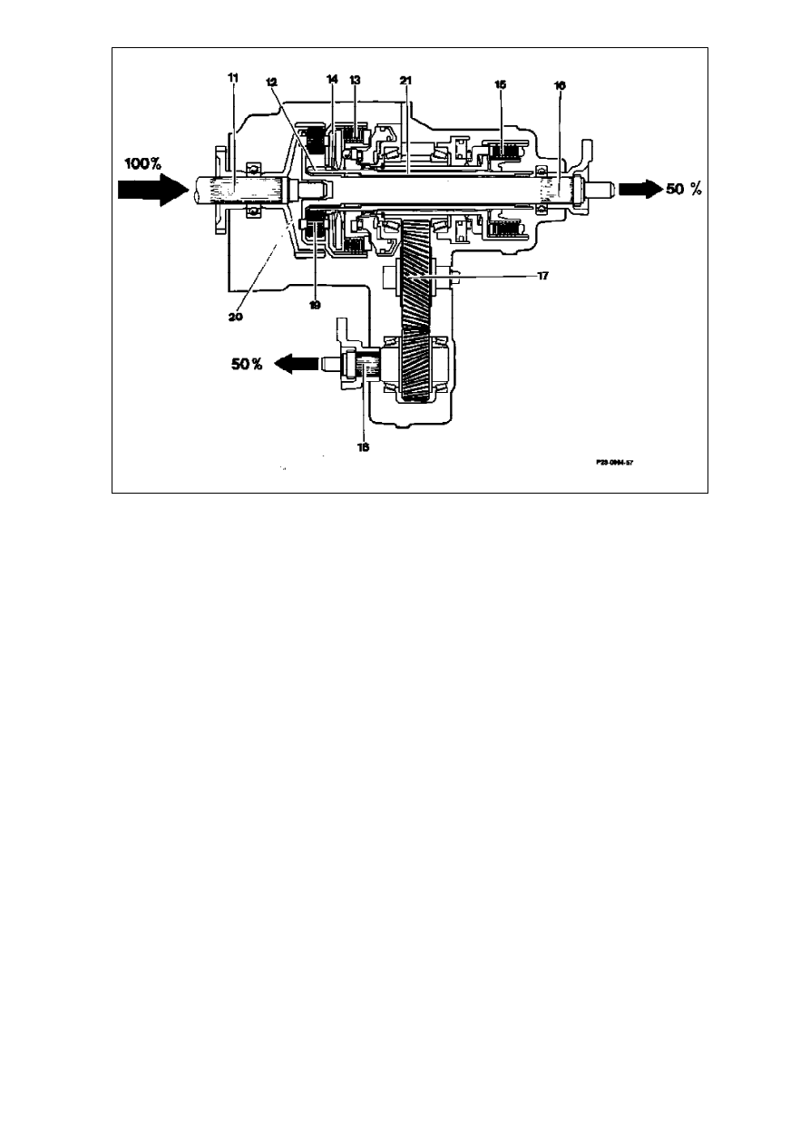
Shift stage 2 - four-wheel drive locked inter-axle
16
Output shaft, rear axle drive train
17
Auxiliary drive
18
Auxiliary drive shaft, front axle drive train
19
Planet gears - center differential
20
Internal-geared wheel, center differential
21
Intermediate shaft
11
Transmission output shaft
12
Center differential
13
Multi-disk clutch - center differential lock (ZS)
14
Diaphragm spring
15
Multi-disk clutch - front axle drive train (AV)
The multi-disk clutches of the center differential
lock (ZS) (13) and the front axle drive train (AV)
(15) are closed.
The center differential (12) is locked.
The drive moment of the transmission output shaft
(11) is transmitted to the output shaft of the rear
axle drive train (16) via the planet carrier and to the
auxiliary output shaft of the front axle drive train
(18) via the sun gear.
The torque distribution corresponds to the
instantaneous traction conditions at the front and
rear wheels. Thus a maximum of 50% of the drive
output can be transmitted to the front-wheel drive.
Shift stage 3 - four-wheel drive locked inter-axle and inter-wheel
65a
Clamping sleeve
66
O-ring (80x2)
67
Breather
68
O-ring (72x3)
69
Radial sealing ring
70
O-ring (63x2,5)
71
Rear axle casing
72
Multi-disk stack
30
Circlip
33b
Connecting flange
37h
Closing plate for H shaft
60
Ring cylinder
61
Annular piston
62
Grooved ball bearing
63
Cup seal
64
Oil baffle
65
Hydraulic line
The multi-disk clutches of the center differential
lock (ZS) and the front axle drive train (AV) are
closed.
The automatic locking differential of the rear axle is
engaged.
In addition to shift stage 2, oil pressure is applied
to the two annular pistons (61) of the
Testing mechanical components
Refer to Diagnosis Manual Chassis Volume 2 - 8.1,
4MATIC
automatic locking differential of the rear axle. With
the connecting flanges (33b) they draw the
differential side gears outwards. The contact force
on the multi-disk stack (72) is thus increased.
These connect the differential side gears to the
differential and thus prevent a speed difference
between the left and right rear wheel.
Wyszukiwarka
Podobne podstrony:
[4matic] funkcjonowanie elektroniki
Formy komunikowania się, Funkcje języka, Blokady komunikacji
BANK CENTRALNY I JEGO FUNKCJE
Zaburzenia funkcji zwieraczy
Genetyka regulacja funkcji genow
BYT 2005 Pomiar funkcjonalnosci oprogramowania
Diagnoza Funkcjonalna
Insulinoterapia funkcjonalna
Postać kanoniczna funkcji kwadratowej
Wpływ choroby na funkcjonowanie rodziny
LAB PROCEDURY I FUNKCJE
STRUKTURA I FUNKCJONOWANIE GN
układ pokarmowy budowa i funkcja
15 Fizjologiczne funkcje nerek
funkcja produkcji
więcej podobnych podstron