
Initial Print Date: 04/07
Table of Contents
Subject
Page
Display and Control Concept . . . . . . . . . . . . . . . . . . . . . . . . . . . . . . . . . . . . .6
Head-up Display (HUD) . . . . . . . . . . . . . . . . . . . . . . . . . . . . . . . . . . . . . . . . .8
One Function, One Control Unit . . . . . . . . . . . . . . . . . . . . . . . . . . . . . . . . .12
Lane Detection . . . . . . . . . . . . . . . . . . . . . . . . . . . . . . . . . . . . . . . . . . . . . . .13
Roadway Markings . . . . . . . . . . . . . . . . . . . . . . . . . . . . . . . . . . . . . . . . . .14
Road Situations . . . . . . . . . . . . . . . . . . . . . . . . . . . . . . . . . . . . . . . . . . . . .15
Environmental Conditions . . . . . . . . . . . . . . . . . . . . . . . . . . . . . . . . . . . .18
Physical Limitations . . . . . . . . . . . . . . . . . . . . . . . . . . . . . . . . . . . . . . . . .20
Lane Departure Warning Control Unit . . . . . . . . . . . . . . . . . . . . . . . . . . . .26
Lane Departure Warning Camera . . . . . . . . . . . . . . . . . . . . . . . . . . . . . . . .28
Colored or Black Roadway Marking . . . . . . . . . . . . . . . . . . . . . . . . . . .28
Vibration Motor . . . . . . . . . . . . . . . . . . . . . . . . . . . . . . . . . . . . . . . . . . . . . . .30
Windscreen . . . . . . . . . . . . . . . . . . . . . . . . . . . . . . . . . . . . . . . . . . . . . . . . . . .31
Button . . . . . . . . . . . . . . . . . . . . . . . . . . . . . . . . . . . . . . . . . . . . . . . . . . . . . . .31
Other Control Units . . . . . . . . . . . . . . . . . . . . . . . . . . . . . . . . . . . . . . . . . . . .31
Lane Departure Warning
Revision Date:

Subject
Page
Body Gateway Module . . . . . . . . . . . . . . . . . . . . . . . . . . . . . . . . . . . . . .31
Calibration . . . . . . . . . . . . . . . . . . . . . . . . . . . . . . . . . . . . . . . . . . . . . . . . . . . .33
Diagnosis . . . . . . . . . . . . . . . . . . . . . . . . . . . . . . . . . . . . . . . . . . . . . . . . . . . . .35
Check Control Message . . . . . . . . . . . . . . . . . . . . . . . . . . . . . . . . . . . . . . .35

BLANK
PAGE

4
Lane Departure Warning
Lane Departure Warning
Model: E60, E61
Production: From 3/2007 Production
Model: E63, E64
Production: From 9/2007 Production
After completion of this module you will be able to:
• Explain the operation of the Lane Departure Warning System
• Identify the Components used in the Lane Departure Warning System
• Understand the operation of the camera

The lane departure warning is available to order from 03/07 as option 5AD for the E60
and E61. The feature will be introduced in 09/07 on the E63 and E64.
Fatigue or inattentiveness on the road can cause a driver to unintentionally leave a lane.
This could result in the vehicle driving into a lane with oncoming traffic or ditches at the
side of the road.
BMW's lane departure warning is a driver assistance system designed to inform the dri-
ver in good time of unintentional course deviations by means of vibrations in the steering
wheel intended to prompt the driver to make corrective steering movements.
The lane departure warning is a driver assistance system. The area in front of the vehicle
is captured by a camera. This makes it possible for the roadway markings to the right and
left of the current lane to be detected.
If the vehicle approaches a roadway marking in the absence of a turn indication, the dri-
ver is informed of the course deviation by steering wheel vibrations before the vehicle
crosses the line.
The camera is fitted near the rear-view mirror behind the windscreen and its camera
images to the control unit on a data line.
The control unit contains the software that determines the position of the vehicle in the
lane from the camera images.
The lane departure warning is designed for operation on highways, major roads and well
maintained country roads. A warning is issued if the system (current driving conditions
within a specific time frame being equal) detects that the vehicle is crossing the roadside
border line. The warning can be felt as a vibrating of the steering wheel.
The lane departure warning is switched on and off using a button on the steering wheel.
When the ignition is switched on, the lane departure warning system always reverts to
the state that was active when the vehicle was last switched off (last function mode).
The display indicating whether the lane departure warning is switched on or off is output
by the instrument cluster or, optionally, by the head-up display. When the lane departure
warning is switched on, there is an additional display indicating whether the system is
primed or not.
Note: The system is only primed if it is switched on and has detected one or
two roadside border lines with the vehicle travelling at a speed faster
than 70 km/h.
5
Lane Departure Warning
Introduction
Display and Control Concept
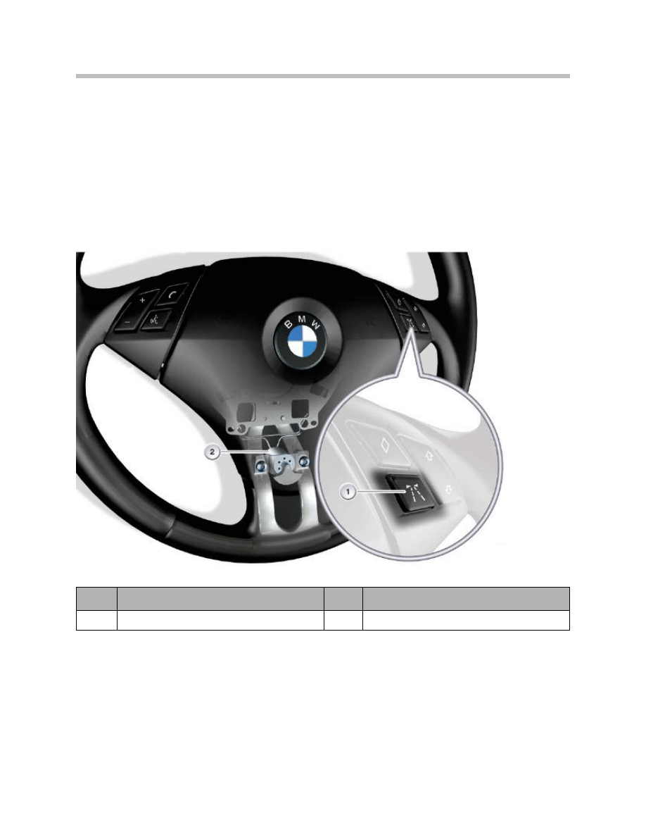
The lane departure warning is switched on and off using the button shown below on the
multi-function steering wheel. The lane departure warning is switched on and off with
each press of the button.
When the ignition is switched on, the lane departure warning system always reverts to the
state that was active when the vehicle was last switched off (last function mode).
Lane departure warning button E60/E61
6
Lane Departure Warning
Index
Explanation
Index
Explanation
1
Lane departure warning button
2
Vibration motor
Note: There is an option to switch the lane departure warning display in the
head-up display on or off on the Central Information Display using the
controller.
7
Lane Departure Warning
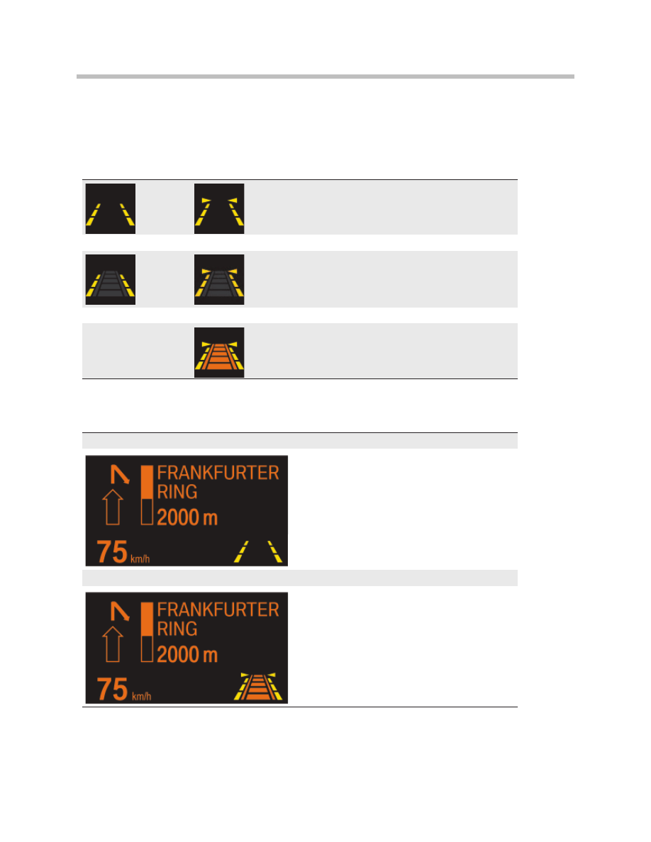
Displays in the instrument cluster
Lane departure
warning ON
Left-hand, right-hand lane or both lanes detected and v > 70
km/h
Display in the instrument cluster with ACC deactivated
Display in the instrument cluster with ACC activated
Displays in the head-up display
Lane departure warning ON
Shown here without the ACC symbol.
Left-hand, right-hand lane detected or both lanes detected and v > 70 km/h
Shown here with the ACC symbol.
The display of the states listed above is the same for the head-up display.
The system function display in the instrument cluster can take the form of the states list-
ed in the following table.
Note: If the vehicle has Active Cruise Control
ACC, the lane departure warning display is
combined with the ACC symbol.
Note: When the ACC display is shown depends
on the driving situation.
8
Lane Departure Warning
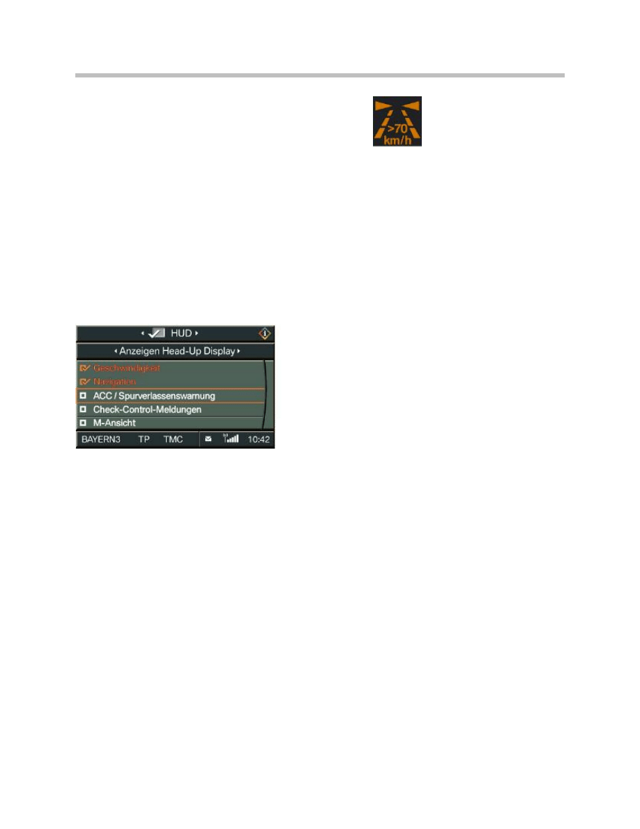
The lane departure warning can be switched on as
of terminal 15 ON. The system is available from a
speed of 70 km/h. The lane departure warning will
also be primed if lanes are detected. If the lane
departure warning is switched on at speeds of under
70 km/h, a message will appear in the instrument
cluster for 3 seconds indicating availability above a
speed of 70 km/h.
Head-up Display (HUD)
It is possible to activate or deactivate the lane departure warning display in the Head-up
Display using the controller.
The activation option is located in the Head-up Display menu > Head-up Display display
options. Select "ACC/lane departure warning" and confirm with the controller.
HUD menu > Head-up Display display options E60
Message indicating the
availability of the lane
departure warning.
9
Lane Departure Warning
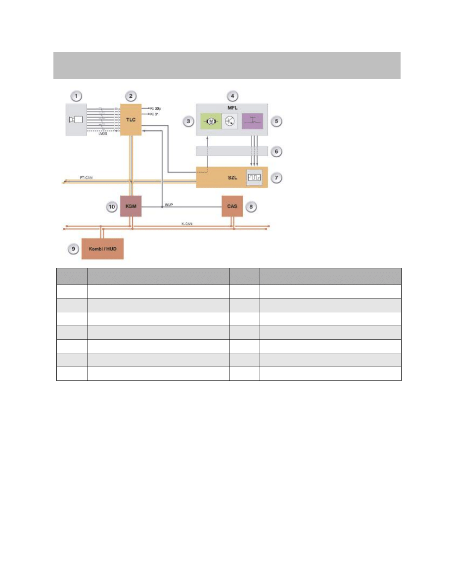
Lane departure warning system overview The lane departure warning system receives a
number of input signals. The image data of camera (1) is evaluated in lane departure
warning control unit (2) together with the other vehicle data that the control unit receives
on the PT-CAN. The lane departure warning is realized from the combination of this data.
Instrument cluster (9) and head-up display (9) output the displays of the lane departure
warning.
Electric motor (3) in multi-function steering wheel (4) produces the vibration of the steer-
ing wheel by means of an imbalance mass.
Body gateway module (10) transfers the PT-CAN messages from the lane departure
warning control unit to the K-CAN and vice versa.
Systems Overview
Index
Explanation
Index
Explanation
1
Lane departure warning camera
8
Car Access System
2
Lane departure warning control unit
9
Instrument cluster/head-up display
3
Vibration motor
10
Body gateway module
4
Multi-function steering wheel
K-CAN
Body CAN
5
Lane departure warning button
PT-CAN
Powertrain CAN
6
Volute spring cassette
W-UP
Wake-up
7
Steering column switch cluster
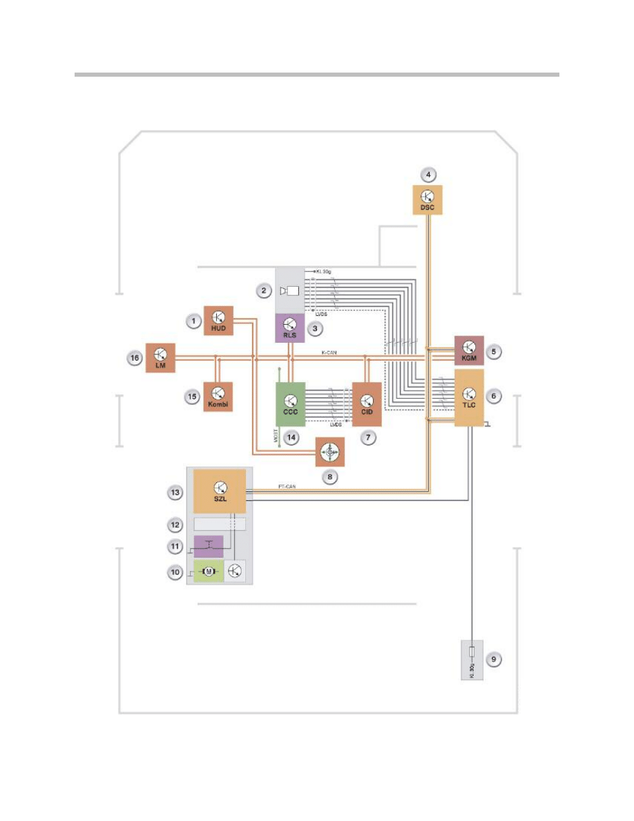
System Schematic Circuit Diagram
10
Lane Departure Warning

11
Lane Departure Warning
Camera (2) sends image data to lane departure warning control unit (6) on the LVDS
data line.
The control unit receives vehicle data on the PT-CAN. The vehicle data includes the sta-
tus of the turn signal steering column switch or the button for the lane departure warning,
for example.
Instrument cluster (15) is able to display whether or not the lane departure warning sys-
tem is switched on. The primed status or availability of the lane departure warning system
is also displayed in the instrument cluster. Using controller (8), it is possible to select an
option to have the information displayed in head-up display (1). The relevant menu
appears in Central Information Display (7).
Index
Explanation
Index
Explanation
1
Head-up display HUD
12
Volute spring cassette
2
Lane departure warning camera
13
Steering column switch cluster SZL
3
Rain/light sensor RLS
14
Car Communication Computer CCC
4
Dynamic Stability Control (DSC)
15
Instrument cluster Kombi
5
Body gateway module
16
Light module LM
6
Lane departure warning control unit
K-CAN
Body CAN
7
Central Information Display CID
PT-
CAN
Powertrain CAN
8
Controller
MOST
Media Oriented System Transport
9
Fuse in the rear distribution box
LVDS
Low Voltage Differential Signalling
10
Vibration motor
KL 30g
Terminal 30 switched
11
Lane departure warning button

12
Lane Departure Warning
One Function, One Control Unit
The lane departure warning system receives a number of input signals.
Details of the input and output signals evaluated by the lane departure warning system
are listed below.
Functions
Input and output signals
Input signal
Sensor control unit
Explanation
Steering wheel angle
Dynamic Stability Control
steering column switch
cluster steering angle sensor
Lane detection assistance
Brake pressure
Dynamic stability control
Brake pressure threshold as warning
cancellation criterion
Road speed
Dynamic stability control
Lane detection assistance
Road speed
Instrument cluster
Control of the primed status display
Terminal status
Car Access System
Control of the operating states of the
lane departure warning control unit
Vehicle identification
number
Car Access System
Detection as to whether the control
unit fitted and the camera match the
vehicle
Engine status
Digital Motor Electronics/
Digital Diesel Electronics
Activation of the processor for image
processing after the engine start
Lane departure warning
button
Steering column switch
cluster
System switch on/off
Direction indicator
Steering column switch
cluster
Suppression of warnings in case of
intentional lane departure
Wiper status
Steering column switch
cluster
Support of lane detection by
detection of when the windscreen
wiper sweeps through the camera
image
Battery voltage
Instrument cluster
Fault code memory
Kilometre reading
Instrument cluster
Fault code memory
Output signal
Sensor control unit
Explanation
Lane departure warning
Instrument cluster
Head-up display
Display of status and primed status
in the instrument cluster and head-
up display
Check control message
Lane departure warning
control unit
Request of the Check Control
message

13
Lane Departure Warning
Lane Detection
The camera is fitted to the windscreen near the rear-view mirror. The camera captures the
roadway up to approximately 40m to the front of the vehicle and up to approximately 5 m
to the right and left.
Using image processing technology, the lane departure warning control unit looks for
possible lane markings in the images captured by the camera.
The software in the control unit also checks which lane markings are delimiting the
current lane in which the vehicle is driving.
From the detected lane markings, the lane departure warning is then calculated for
the vehicle.
14
Lane Departure Warning
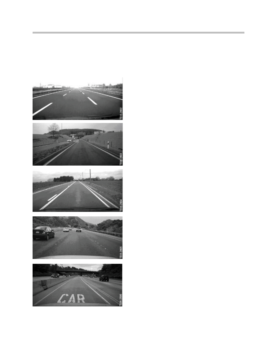
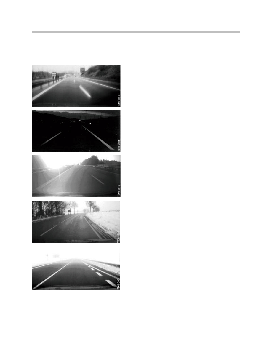
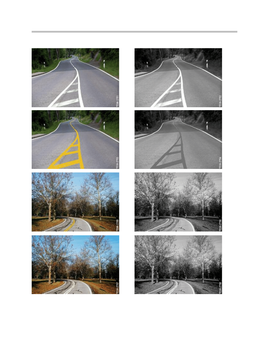
Roadway Markings
The roadway markings in the image may differ greatly depending on the type of road,
environmental conditions or country. The system is able to detect various types of road-
way marking in a number of situations.
Type of Roadway Marking
Explanation
Broken Lines
Unbroken Lines
Double Lines
Bott’s Dots
“Car Pool” Lanes
15
Lane Departure Warning
Road Situations
The lane departure warning is able to handle various road situations.
Type of Roadway Marking
Explanation
Roads with only a Center Line (edge of road on left-
hand side not detected)
Roads without Center Line
Highway Exit
Highway Access
Turn-off
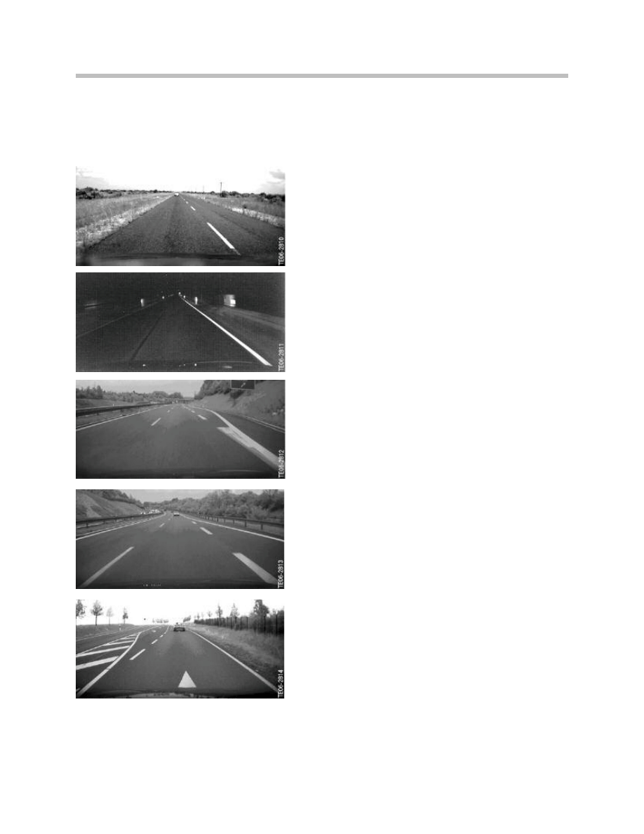
16
Lane Departure Warning
Type of Roadway Marking
Explanation
Hatched Zones
Short Breaks in the Marking

17
Lane Departure Warning
NOTES
PAGE
18
Lane Departure Warning
Environmental Conditions
The lane departure warning functions under different environmental conditions.
Type of Roadway Marking
Explanation
Rain/wet Asphalt
Night
Low-Level Sun
Snow
Fog
19
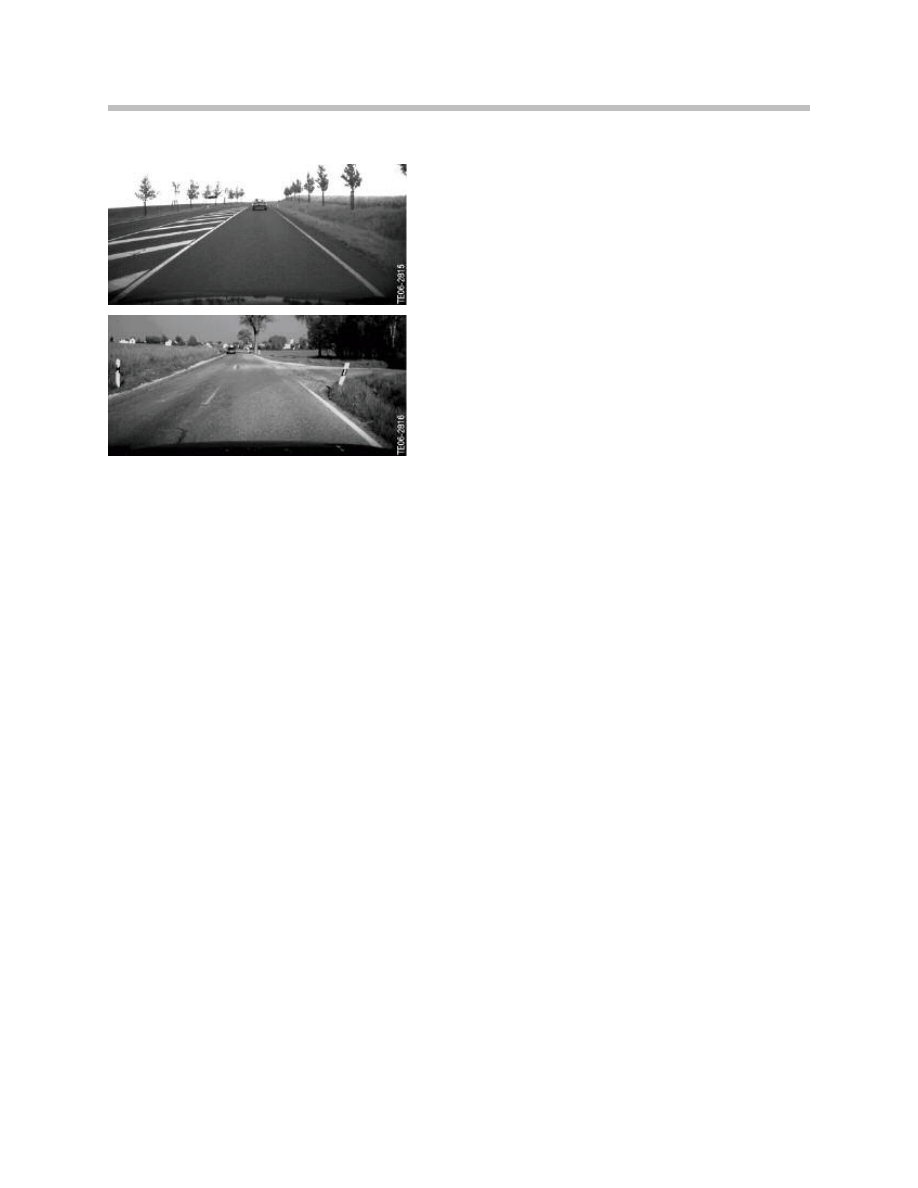
Lane Departure Warning
Type of Roadway Marking
Explanation
Light Colored Asphalt
Dark Asphalt
Tar Seams on the Road
Oncoming Vehicles
20
Lane Departure Warning
Physical Limitations
Systems functionality may be restricted under various road and environmental conditions
due to physical limitations.
Type of Roadway Marking
Explanation
Construction Sites
On roads with worn, poorly visible or inadequately
painted lane markings.
On roads with colored or black lane markings
On roads on which the lane markings are covered by
water, dirt, snow or ice.
On roads with sharp bends.
21
Lane Departure Warning
Type of Roadway Marking
Explanation
On roads with no distinct lane markings
On roadways that are too narrow
If the vehicle comes too close to a vehicle in front
that the camera is unable to see the lane markings
within the detection range.
If the view of the camera is blocked by dirt, snow,
ice or other obstructions on the windscreen.
In very poor weather conditions (rain, fog, snow, etc.)
If intense light shines into the camera from the front
or fades out the lane markings.
22
Lane Departure Warning
Availability of the Lane Departure Warning
The system is available when:
• No system fault is present.
• The lane departure warning system is calibrated correctly.
• The vehicle speed is above the activation threshold (see following table).
• At least one roadway marking has been detected by the system with sufficient
certainty.
• The vehicle is not in a construction site area with several possible roadway markings.
• The vehicle is on a road with an average lane width of more than 2.5 m.
The speed threshold above which the lane departure warning can be available has been
adapted to country-specific conditions. In the US the activation threshold is 45 mph and
deactivation threshold is 42 mph.
Warning Output
The lane departure warning function only outputs a warning to the driver if the system is
switched on and available.
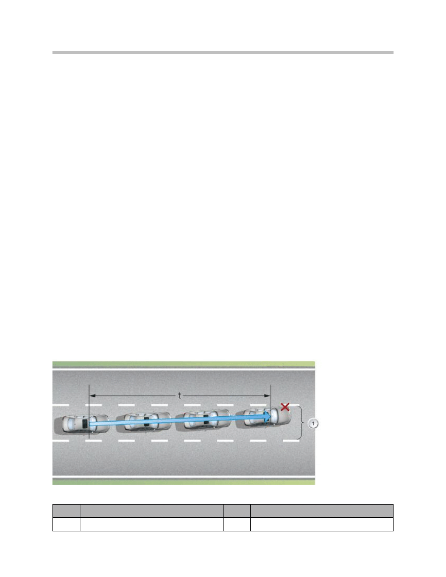
Warning Point
The system outputs the warning to the driver if the driver approaches a detected roadway
marking. To do so, the system calculates the anticipated time (t) before the roadway
marking is crossed. The warning is output in time before the vehicle crosses the marking.
Since warning situations may arise more frequently on narrow roads, the warning is out-
put later by tendency on these kinds of road.
Index
Explanation
Index
Explanation
1
Current Lane
t
Calculated time before point X
Warning output of the lane departure warning E60

23
Lane Departure Warning
Warning Duration
The warning ends when:
• The driver steers back into the lane.
• A lane change is completed.
• The vehicle drives on the line for longer than 2.5 s.
• The turn signal is operated.
• The brake pedal is depressed with force (brake-pressure-dependent).
Note: A warning is output only once on approach to a roadway marking. The
warning lasts no more than 2.5 s. If the vehicle remains on the line, no
new warning will be issued. A new warning can only be issued if the vehi-
cle has been steered back into the lane or the vehicle has completed a
change of lane.
Suppression of the Warning
A warning is suppressed despite the display of primed status if the following conditions
exist on one side:
• Turn signal operated before the vehicle is driven towards the warning trigger.
• One-touch turn signal indicated on the side from which a warning would be
triggered.
There is no warning suppression if the hazard warning flashers are switched on.

24
Lane Departure Warning
The most important components for the lane departure warning are:
• Lane departure warning control unit
• Lane departure warning camera
• Vibration motor in the multi-function steering wheel
• Windscreen
• Button
• Low Voltage Differential Signalling line
• Other control units
– Steering column switch cluster SZL
– Car Access System
– Instrument cluster/head-up display
– Body gateway module
• Other components
– Mirror caps
– Cable finisher
– Headlining
– Mirror base with high beam assistant
System Components
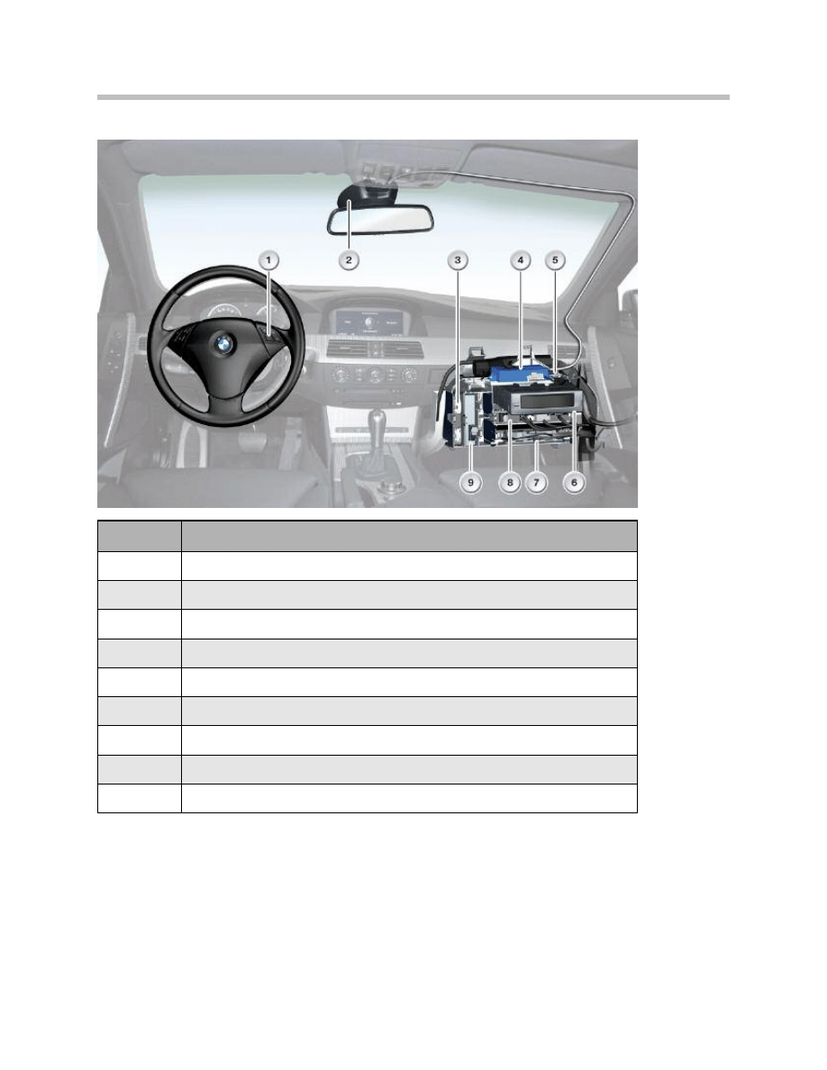
Component Overview (example of E61)
25
Lane Departure Warning
Index
Explanation
1
Lane departure warning button
2
Lane departure warning camera
3
Panorama glass sunroof control unit
4
Lane departure warning control unit
5
Control unit holder
6
CD changer
7
Body basic module
8
Body gateway module
9
Comfort Access
26
Lane Departure Warning
Lane Departure Warning Control Unit
The control unit is accommodated in a 2/3 shell-type housing. For EMC reasons,
the housing is made entirely of aluminum. It has two connectors:
• 12-pin connection to the vehicle electrical system
• 10-pin connection to the LVDS line.
The control unit has two processors. One processor is for communicating with the vehi-
cle electrical system on the PT-CAN. The second processor is used to calculate the lane
departure warning.
The communication processor is activated as soon as terminal 30g is ON. Messages can
now be sent and processed on the PT-CAN. The control unit itself is still in sleep mode.
From terminal 15 ON, the control unit reports to the vehicle electrical system on a cyclical
basis. The control unit only becomes operational once the Engine running signal is pre-
sent. This is because it is only at this point that the high-performance computer, whose
responsibilities include image processing, is activated.
The high-performance computer evaluates the image data of the camera together with
the other vehicle data that the control unit receives on the PT-CAN. The lane departure
warning is realized from the combination of this data.
During operation of the wipe/wash system, the sweep of the wiper blades also takes them
through the field of view of the lane departure warning's camera. For this reason, the con-
trol unit for the lane departure warning receives information about whether the wipe/wash
system is switched on or off.
Index
Explanation
1
LVDS Connection
2
Vehicle Electrical System Connection

27
Lane Departure Warning
Installation Location
The control unit is secured by a bracket to the support tube above the glove compart-
ment.
Overvoltage/Undervoltage Behavior
The voltage range in which the control unit operates is 9.0 V to 16.0 V.
Wake-up
The control unit for the lane departure warning is woken by the wake-up signal of the
control units on the PT-CAN.
Sleep Mode
In sleep mode, the control unit is switched off.
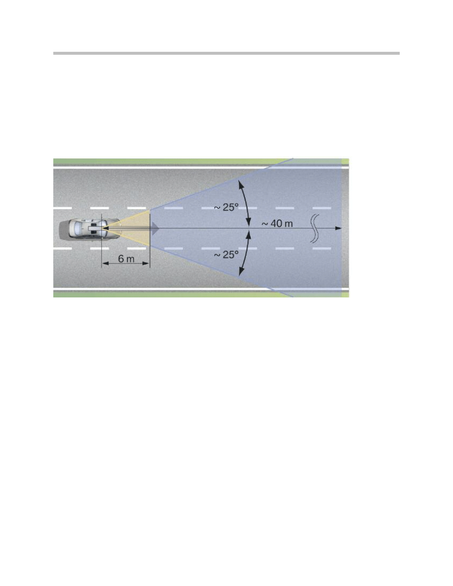
Lane Departure Warning Camera
The camera is fitted behind the windscreen at the base of the rear-view mirror. The cam-
era for the lane departure warning captures the surrounding area, and therefore the lane
markings, to the front of the vehicle.
The camera's scope of detection ranges from approximately 4 m to 40 m ahead of the
vehicle. The camera has a horizontal aperture angle of approximately 50°, and a vertical
aperture angle of approximately 30°.
The camera is a digital black/white CMOS camera. This means that the captured sur-
roundings are output as a grayscale image.
Colored or Black Roadway Marking
Roadway markings Colored yellow, blue, red or black are also represented in grayscale.
The grayscale image may stand out poorly, or not at all, from the grey road surface.
In unfavorable situations, this could mean that these lanes cannot be detected.
Note: If no lane is detected, the lane departure warning does not display
primed status.
28
Lane Departure Warning
Detection range of the lane departure warning camera using the E60 as an example
Lane detection with the eye
Lane detection with the camera
29
Lane Departure Warning
30
Lane Departure Warning
Camera Size
The graphic below illustrates the size of the camera by comparison with the vehicle's
remote control.
Camera Objective
The camera objective has several glass lenses. They are coated to diminish or even fully
eliminate scattered light and thereby increase the image quality of the camera.
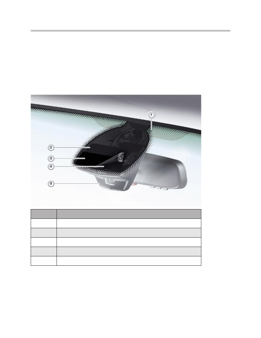
Vibration Motor
The vibration motor and its electronics are fully integrated inside the steering wheel.
The vibration motor is fitted in the six o'clock spoke of the steering wheel.
To generate the vibration, there is a small imbalance mass on the shaft of the vibration
motor. The vibration motor is controlled directly by the control unit. The electronics in the
steering wheel are used to convert the control voltage supplied by the control unit into
the voltage value required by the motor and to provide its stabilization. The control voltage
corresponds to the on-board voltage.
The motor with imbalance mass issues a warning if the vehicle threatens to leave the
current lane by causing the steering wheel to vibrate.
Index
Explanation
1
Camera
2
Lens Shade
3
LVDS Connector
Index
Explanation
1
Vibration Motor
2
Imbalance mass
3
LVDS Connector

31
Lane Departure Warning
Windscreen
The lane departure warning requires a windscreen matched to the system. The wind-
screen has a wider, black print that conceals the camera and a camera holder bonded on.
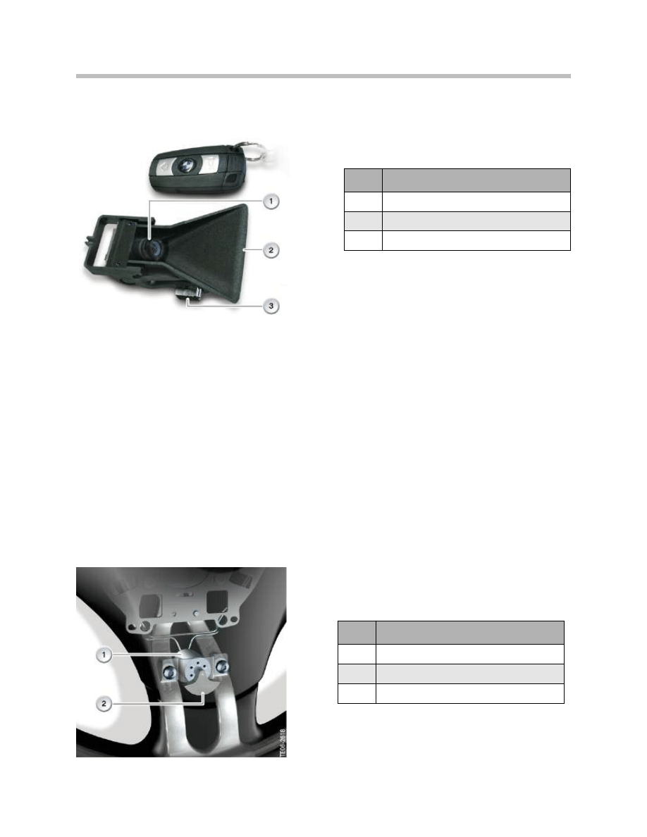
Button
The SZL records the requests input at the button and sends them to the lane departure
warning control unit on the PT-CAN.
Other Control Units
Steering Column Switch Cluster
The vibration motor in the steering wheel is connected directly to the lane departure
warning control unit by the SZL and the slip ring.
All steering wheels equipped with steering wheel heating LHZ require an SZL with steer-
ing wheel heating. These SZLs are compatible with the lane departure warning.
For steering wheels without LHZ, there is a special variant of the steering column switch
cluster for the lane departure warning.
Car Access System
The CAS control unit controls the wake-up line and thus also the waking of the control
unit for the lane departure warning.
Instrument Cluster/Head-up Display
The instrument cluster and the head-up display display the activation status when the
lane departure warning is switched on.
Note: The message indicating availability of the lane departure
warning is only displayed in the instrument cluster.
A corresponding Check Control message is displayed in the event of a fault anywhere in
the lane departure warning system.
Body Gateway Module
The body gateway module transfers messages from the lane departure warning control
unit (PT-CAN) to the K-CAN. The same applies in the opposite direction.
32
Lane Departure Warning
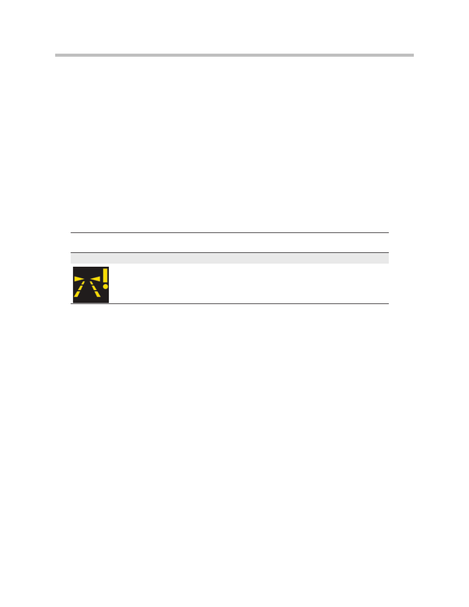
Other Components
Mirror Caps, Cable Finisher, Headlining
The lane departure warning system has wider mirror caps to conceal the camera, a cable
finisher and a larger headlining cutout.
Mirror Base With High Beam Assistant
When fitted in combination with the high beam assistant (FLA), the system has a special
mirror base for package reasons.
Index
Explanation
1
Headlining cutout with cable end
2
Rain/light sensor
3
Condensation sensor
4
Lane departure warning camera
5
Mirror caps/high beam assistant

33
Lane Departure Warning
Calibration
If the system is to be able to calculate the distance to a given roadway marking, it must
know the exact installation position of the camera on the one hand, and the camera's
exact focal direction on the other.
Due to installation tolerances and tolerances inside the camera, the position of the cam-
era's viewing angle may vary by several degrees.
The exact installation position of the camera and its installation angle are determined
during calibration of the system and stored in the system.
In production, there is a dedicated calibration bench for this process that determines the
measured variables by means of sample boards, which are arranged in a defined posi-
tion relative to the vehicle.
Any replacement of the camera or windscreen requires a calibration of the system
because the position of the camera and thus of the system sensor may have changed.
No calibration is required if the control unit is replaced. In this case, the calibration data
stored in the camera is transferred to the control unit and stored there.
Each time the system is started, a check takes place to determine whether the system is
calibrated and whether the system components are matched to each other and the vehi-
cle. In this regard, the Vehicle Identification Number VIN stored in the control unit is com-
pared with that of the vehicle's.
With this plausibility check, it can be determined whether the control unit is coded cor-
rectly and whether it belongs to the vehicle.
The VIN stored in the camera is then compared with the VIN stored in the control unit. If
discrepancies are detected, the system detects that a camera requiring new calibration
has been fitted and it outputs a corresponding fault code. For more details, please refer
to the BMW diagnostic system or the repair instructions.
Note: A windscreen replacement cannot be detected by the system. In this
case, the aftersales service organization is responsible for ensuring
that the system is newly calibrated.
Service Information

34
Lane Departure Warning
To have the system calibrated in the aftersales service organization, a diagnostics job is
started. This diagnostics job investigates whether the camera is functional and has free
line of sight. This is determined from the detection of movements in front of the camera.
Free line of sight can be determined by having someone walk by in front of the camera,
for example.
Calibration starts automatically on successful completion of this test step (good camera
image). Calibration takes place during a calibration run, which can be carried out by the
customer. In the event that the camera test failed, the calibration process is terminated
and must be restarted after the possible interfering factors have been remedied.
A specially developed algorithm is used for calibrating the system during the calibration
run. This algorithm scans the image for all straight edges and, from their orientation,
determines the viewing angle of the camera.
The calibration algorithm works from a speed of 30 km/h. For evaluation purposes, it
essentially uses images captured during straight-ahead travel. As soon as enough infor-
mation has been recorded, the viewing angle is calculated and stored in the control unit.
This process generally takes a few minutes. In conditions of poor visibility, e.g. night, rain
or winding roads, the calibration process may take up to 20 minutes.
The calibration run does not have to be completed during the first drive following the start
of the diagnostics job. It is reset with each power cycle and restarted again until it has
been successfully completed.
The system can be switched on and off during the calibration process. When the lane
departure warning has been calibrated, the primed status display is shown when the lane
departure warning is on. The conditions for this are:
• speed of over 70 km/h
• lane markings detected.
Following a replacement, e.g. of the control unit, the camera or the windscreen, it is nec-
essary to recalibrate the lane departure warning.
The customer is notified by a Check Control message if the calibration process cannot
be completed successfully after a net time of 7 minutes of straight-ahead travel at over
60 km/h.
The system then makes an automatic attempt to carry out calibration again. If this
attempt under the conditions described above is unsuccessful, the system makes anoth-
er attempt at calibration. A new Check Control message is only ever output after a power
cycle following the first unsuccessful calibration attempt.
35
Lane Departure Warning
This process repeats itself until calibration has been successfully completed. If the cali-
bration run does not complete successfully, the vehicle must be brought into the after-
sales service organization. In the after-sales service organization, the calibration process
can be terminated manually using a diagnostics job.
After the calibration process has been terminated, it must then be restarted once more.
Diagnosis
The control unit for the lane departure warning is compatible with diagnostics. The fault
code memory can be read using the BMW diagnostic system.
For test purposes, there is an option for controlling the vibration motor or the camera, for
example. You will find more detailed information in the BMW diagnostic system.
Check Control Message
The Check Control messages are output by the lane departure warning or the instrument
cluster. If the control unit for the lane departure warning is faulty, it sends a request to
have a Check Control message displayed.
If the signal from the lane departure warning drops out, the instrument cluster generates
a Check Control message.
If a Check Control message is output, system availability is simply no longer displayed but
the activation indication continues to be displayed in the instrument cluster or the head-
up display, provided the system is activated.
Check control
message
Description
Information in central information display
Lane departure
warning malfunction!
Lane departure warning malfunction!
Please visit the nearest BMW Service.
Document Outline
- Main Menu
- Lane Departure Warning
- USB/Audio Interface
- IBOC Update.
- E60/E61 Model Update
- Longitudinal Dynamics Systems
- M Model Updates
Wyszukiwarka
Podobne podstrony:
04a Lane Departure Warning
Amy Lane [Little Goddess 01] Vulnerable
01 Shawn Lane Accidentally His
Thom Lane Tales of Amaranth 01 Dark Heart
Amy Lane Little Goddess 01 Vulnerable
Mullins Eustace, Warning The Department Of Justice Is Dangerous To Americans (1989)
TD 01
Ubytki,niepr,poch poł(16 01 2008)
01 E CELE PODSTAWYid 3061 ppt
01 Podstawy i technika
01 Pomoc i wsparcie rodziny patologicznej polski system pomocy ofiarom przemocy w rodzinieid 2637 p
zapotrzebowanie ustroju na skladniki odzywcze 12 01 2009 kurs dla pielegniarek (2)
01 Badania neurologicz 1id 2599 ppt
01 AiPP Wstep
ANALIZA 01
01 WPROWADZENIA
01 piątek
więcej podobnych podstron