9•1
Chapter 9 Braking system
Contents
Anti-lock Braking System (ABS) - general information 22
Anti-lock Braking System (ABS) components - removal and
refitting 23
Brake pedal - removal and refitting 14
Front brake caliper - removal, overhaul and refitting 10
Front brake disc - inspection, removal and refitting 7
Front brake pad wear check See Chapter 1
Front brake pads - renewal 4
General information 1
Handbrake - adjustment 17
Handbrake cables - removal and refitting 19
Handbrake lever - removal and refitting 18
Hydraulic fluid level check See Chapter 1
Hydraulic fluid renewal See Chapter 1
Hydraulic pipes and hoses - renewal 3
Hydraulic system - bleeding 2
Degrees of difficulty
Master cylinder - removal, overhaul and refitting 13
Rear brake caliper - removal, overhaul and refitting 11
Rear brake disc - inspection, removal and refitting 8
Rear brake drum - removal, inspection and refitting 9
Rear brake pad wear check See Chapter 1
Rear brake pads - renewal 5
Rear brake pressure-regulating valves (models
with rear disc brakes) - removal and refitting 20
Rear brake shoe wear check See Chapter 1
Rear brake shoes - renewal 6
Rear wheel cylinder - removal and refitting 12
Stop-light switch - removal, refitting and adjustment 21
Vacuum pump (16-valve models) - removal and refitting 24
Vacuum pump (16-valve models) - testing and overhaul 25
Vacuum servo unit - testing, removal and refitting 15
Vacuum servo unit check valve - removal, testing and refitting . . . . 16
Easy, suitable for
novice with little
experience
Fairly easy, suitable
for beginner with
some experience
Fairly difficult, suitable
for competent DIY
mechanic
Difficult, suitable for
experienced DIY
mechanic
Very difficult,
suitable for expert DIY
or professional
Specifications
Front brakes
Type Disc, with single-piston sliding caliper
Disc diameter:
16-valve models 266 mm
All other models 247 mm
Disc thickness:
New:
Solid disc 10 mm
Ventilated disc 20.4 mm
Minimum thickness:
Solid disc 8.0 mm
Ventilated disc 18.4 mm
Maximum disc run-out 0.2 mm
Brake pad minimum thickness 2.0 mm
Rear brakes
Type:
Larger-engined models,
and all models with ABS Disc, with single-piston sliding caliper
All other non-ABS models Single leading shoe drum
Drum brakes:
Drum diameter:
New 180 mm
Maximum diameter after machining 182 mm
Brake shoe thickness:
New 4.85 mm
Minimum 1.5 mm
Disc brakes:
Disc diameter 247 mm
Disc thickness:
New 8.0 mm
Minimum thickness 6.0 mm
Maximum disc run-out 0.2 mm
Brake pad minimum thickness 2.0 mm
9•2 Braking system
ABS system
Wheel sensor-to-reluctor ring air gap 0.3 to 1.2 mm
Torque wrench settings Nm
Front brake caliper:
Guide pin bolts (Girling caliper) 35
Mounting bracket-to-swivel hub bolts 120
Rear brake caliper mounting bolts 120
Rear hub nut:
Models with rear drum brakes 200
Models with rear disc brakes 180
Master cylinder-to-servo unit nuts 10
Brake pedal pivot bolt 25
Pedal bracket retaining nuts 5
Vacuum servo unit mounting nuts 20
ABS wheel sensor retaining bolts 9
Roadwheel bolts 90
Ibfft
26
89
89
148
133
7
18
4
15
7
66
The braking system is of the servo-
assisted, dual-circuit hydraulic type. The
arrangement of the hydraulic system is such
that each circuit operates one front and one
rear brake from a tandem master cylinder.
Under normal circumstances, both circuits
operate in unison. However, in the event of
hydraulic failure in one circuit, full braking
force will still be available at two wheels.
Most large-capacity engine models have
disc brakes all round as standard; all other
models not equipped with the Anti-lock
Braking System (ABS) are fitted with front disc
brakes and rear drum brakes. ABS is fitted as
standard to the 16-valve model, and was
offered as an option on most other models; on
models equipped with ABS, disc brakes are
fitted at both the front and rear (refer to
Section 22 for further information on ABS
operation).
The front disc brakes are actuated by
single-piston sliding type calipers, which
ensure that equal pressure is applied to each
disc pad.
On models with rear drum brakes, the rear
brakes incorporate leading and trailing shoes,
which are actuated by twin-piston wheel
cylinders. The wheel cylinders incorporate
integral pressure-regulating valves, which
control the hydraulic pressure applied to the
rear brakes. The regulating valves help to
prevent rear wheel lock-up during emergency
braking. A self-adjust mechanism is
incorporated, to automatically compensate for
brake shoe wear. As the brake shoe linings
wear, the footbrake operation automatically
operates the adjuster mechanism, which
effectively lengthens the shoe strut and
repositions the brake shoes, to remove the
lining-to-drum clearance.
On models with rear disc brakes, the
brakes are actuated by single-piston sliding
calipers which incorporate mechanical
handbrake mechanisms. A pressure-
regulating valve is situated in the brake line to
each rear caliper. The regulating valve is
similar to that fitted to the rear wheel cylinders
on drum brake models, and helps to prevent
rear wheel lock-up during emergency braking.
On all models, the handbrake provides an
independent mechanical means of rear brake
application.
On 16-valve models, due to the ACAV
intake system, there is insufficient vacuum in
the inlet manifold to operate the braking
system servo effectively at all times. To
overcome this problem, a vacuum pump is
fitted to the engine, to supplement the inlet
manifold vacuum and ensure that sufficient
vacuum is always present in the servo unit.
The vacuum pump is mounted on the end of
the cylinder head, and driven directly off the
end of the inlet camshaft.
Note: When servicing any part of the
system, work carefully and methodically; also
observe scrupulous cleanliness when
overhauling any part of the hydraulic system.
Always renew components (in axle sets, where
applicable) if in doubt about their condition,
and use only genuine Citroen replacement
parts, or at least those of known good quality.
Note the warnings given in "Safety first" and at
relevant points in this Chapter concerning the
dangers of asbestos dust and hydraulic fluid.
Warning: Hydraulic fluid is
poisonous; wash off immediately
and thoroughly in the case of skin
contact, and seek immediate
medical advice if any fluid is swallowed or
gets into the eyes. Certain types of hydraulic
fluid are inflammable, and may ignite when
allowed into contact with hot components;
when servicing any hydraulic system, it is
safest to assume that the fluid is
inflammable, and to take precautions against
the risk of fire as though it is petrol that is
being handled.. Finally, it is hygroscopic (it
absorbs moisture from the air) - old fluid may
be contaminated and unfit for further use.
When topping-up or renewing the fluid,
always use the recommended type, and
ensure that it comes from a freshly-opened
sealed container.
General
1 The correct operation of any hydraulic
system is only possible after removing all air
from the components and circuit; -this is
achieved by bleeding the system.
2 During the bleeding procedure, add only
clean, unused hydraulic fluid of the
recommended type; never re-use fluid that
has already been bled from the system.
Ensure that sufficient fluid is available before
starting work.
3 If there is any possibility of incorrect fluid
being already in the system, the brake
components and circuit must be flushed
completely with uncontaminated, correct
fluid, and new seals should be fitted to the
various components.
4 If hydraulic fluid has been lost from the
system, or air has entered because of a leak,
ensure that the fault is cured before
proceeding further.
5 Park the vehicle on level ground, switch off
the engine and select first or reverse gear, then
chock the wheels and release the handbrake.
6 Check that all pipes and hoses are secure,
unions tight and bleed screws closed. 'Clean
any dirt from around the bleed screws.
7 Unscrew the master cylinder reservoir cap,
and top the master cylinder reservoir up to the
"MAX" level line; refit the cap loosely, and
remember to maintain the fluid level at least
above the "MIN" level line throughout the
procedure, or there is a risk of further air
entering the system.
8 There are a number of one-man, do-it-
yourself brake bleeding kits currently available
2 Hydraulic system - bleeding
1 General information
Hydraulic fluid is an effective
paint stripper, and will attack
plastics; if any is spilt, it
should be washed off
immediately, using copious quantities
of fresh water
Braking system 9•3
from motor accessory shops. It is
recommended that one of these kits is used
whenever possible, as they greatly simplify
the bleeding operation, and also reduce the
risk of expelled air and fluid being drawn back
into the system. If such a kit is not available,
the basic (two-man) method must be used,
which is described in detail below.
9 If a kit is to be used, prepare the vehicle as
described previously, and follow the kit
manufacturer's instructions, as the procedure
may vary slightly according to the type being
used; generally, they are as outlined below in
the relevant sub-section.
10 Whichever method is used, the same
sequence must be followed (paras 11 and 12)
to ensure the removal of all air from the system.
Bleeding sequence
11 If the system has been only partially
disconnected, and suitable precautions were
taken to minimise fluid loss, it should be
necessary only to bleed that part of the
system (ie the primary or secondary circuit).
12 If the complete system is to be bled, then
it should be done working in the following
sequence:
Non-ABS models
(a) Left-hand rear brake.
(b) Right-hand front brake.
(c) Right-hand rear brake.
(d) Left-hand front brake.
ABS models
(a) Left-hand front brake.
(b) Right-hand front brake.
fc) Left-hand rear brake,
(d) Right-hand rear brake.
Note: If difficulty is experienced in bleeding
the braking circuit on models with ABS, try
bleeding the complete system working in the
reverse of the specified sequence, starting
with the right-hand rear brake and finishing
with the left-hand front brake.
Bleeding - basic (two-man)
method
13 Collect a clean glass jar, a suitable length
of plastic or rubber tubing which is a tight fit
over the bleed screw, and a ring spanner to fit
the screw. The help of an assistant will also be
required.
14 Remove the dust cap from the first screw
in the sequence. Fit the spanner and tube to
the screw, place the other end of the tube in
the jar, and pour in sufficient fluid to cover the
end of the tube.
15 Ensure that the master cylinder reservoir
fluid level is maintained at least above the
"MIN" level line throughout the procedure.
16 Have the assistant fully depress the brake
pedal several times to build up pressure, then
maintain it on the final downstroke.
17 While pedal pressure is maintained,
unscrew the bleed screw (approximately one
turn) and allow the compressed fluid and air to
flow into the jar. The assistant should maintain
pedal pressure, following it down to the floor if
necessary, and should not release it until
instructed to do so. When the flow stops,
tighten the bleed screw again, have the
assistant release the pedal slowly, and
recheck the reservoir fluid level.
18 Repeat the steps given in paragraphs 16
and 17 until the fluid emerging from the bleed
screw is free from air bubbles. If the master
cylinder has been drained and refilled, and air
is being bled from the first screw in the
sequence, allow approximately five seconds
between cycles for the master cylinder
passages to refill.
19 When no more air bubbles appear, tighten
the bleed screw securely, remove the tube
and spanner, and refit the dust cap. Do not
overtighten the bleed screw.
20 Repeat the procedure on the remaining
screws in the sequence, until all air is
removed from the system and the brake pedal
feels firm again.
Bleeding - using a one-way valve kit
21 As their name implies, these kits consist of
a length of tubing with a one-way valve fitted,
to prevent expelled air and fluid being drawn
back into the system; some kits include a
translucent container, which can be positioned
so that the air bubbles can be more easily
seen flowing from the end of the tube.
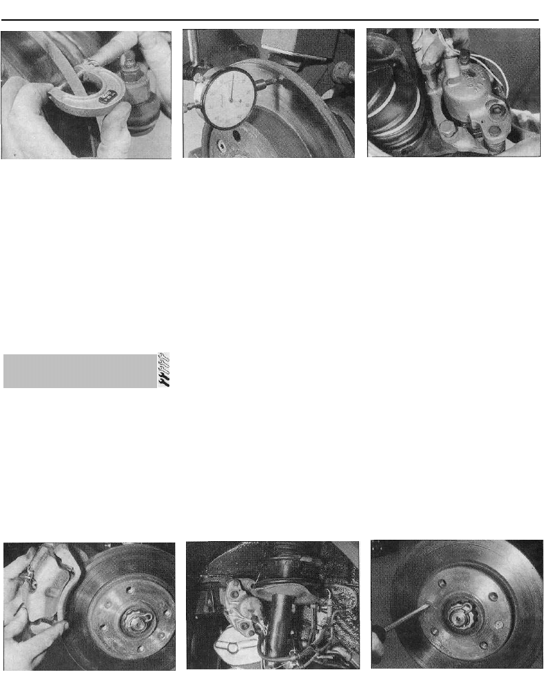
22 The kit is connected to the bleed screw,
which is then opened. The user returns to the
driver's seat, depresses the brake pedal with
a smooth, steady stroke, and slowly releases
it; this is repeated until the expelled fluid is
clear of air bubbles (see illustration).
23 Note that these kits simplify work so
much that it is easy to forget the master
cylinder reservoir fluid level; ensure that this is
maintained at least above the "MIN" level line
at all times.
Bleeding - using a pressure-
bleeding kit
24 These kits are usually operated by the
reservoir of pressurised air contained in the
spare tyre. However, note that it will probably
be necessary to reduce the pressure to a
lower level than normal; refer to the
instructions supplied with the kit.
25 By connecting a pressurised, fluid-filled
container to the master cylinder reservoir,
bleeding can be carried out simply by opening
each screw in turn (in the specified sequence),
and allowing the fluid to flow out until no more
air bubbles can be seen in the expelled fluid.
26 This method has the advantage that the
large reservoir of fluid provides an additional
safeguard against air being drawn into the
system during bleeding.
27 Pressure-bleeding is particularly effective
when bleeding "difficult" systems, or when
bleeding the complete system at the time of
routine fluid renewal.
All methods of bleeding
28 When bleeding is complete, and firm
pedal feel is restored, wash off any spilt fluid,
tighten the bleed screws securely, and refit
their dust caps.
2.22 Bleeding a rear brake caliper using a
one-way valve kit
29 Check the hydraulic fluid level in the
master cylinder reservoir, and top-up if
necessary (Chapter 1).
30 Discard any hydraulic fluid that has been
bled from the system; it will not be fit for re-
use.
31 Check the feel of the brake pedal. If it
feels at all spongy, air must still be present in
the system, and further bleeding is required.
Failure to bleed satisfactorily after a
reasonable repetition of the bleeding
procedure may be due to worn master
cylinder seals.
Note: Before starting work, refer to the note at
the beginning of Section 2 concerning the
dangers of hydraulic fluid.
1 If any pipe or hose is to be renewed,
minimise fluid loss by first removing the
master cylinder reservoir cap, then tightening
it down onto a piece of polythene to obtain an
airtight seal. Alternatively, flexible hoses can
be sealed, if required, using a proprietary
brake hose clamp; metal brake pipe unions
can be plugged (if care is taken not to allow
dirt into the system) or capped immediately
they are disconnected. Place a wad of rag
under any union that is to be disconnected, to
catch any spilt fluid.
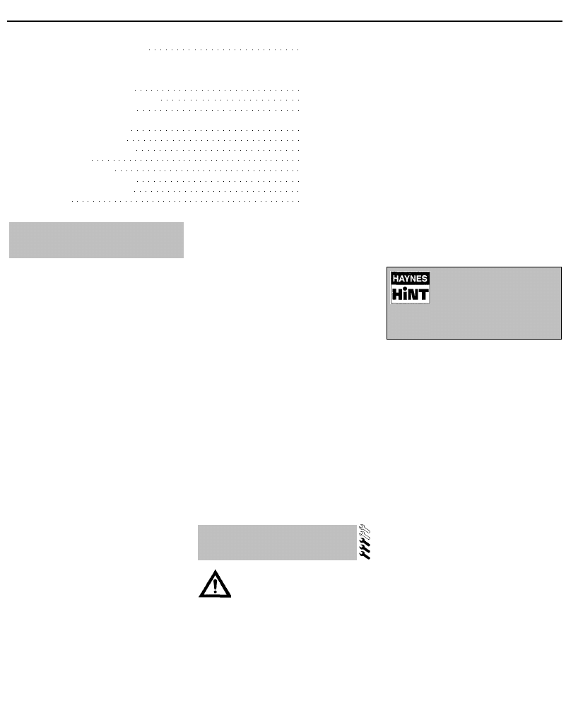
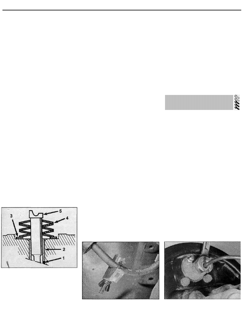
2 If a flexible hose is to be disconnected,
unscrew the brake pipe union nut before
removing the spring clip which secures the
hose to its mounting bracket (see illustration).
3.2 Hydraulic pipe-to-flexible hose
connection
1 Union nut 4 Splined end fitting
2 Flexible hose 5 Mounting bracket
3 Spring clip support
3 Hydraulic pipes and hoses -
renewal
9•4 Braking system
4.2 Disconnecting the pad wear sensor
wiring from its connector
3 To unscrew the union nuts, it is preferable
to obtain a brake pipe spanner of the correct
size; these are available from most large
motor accessory shops. Failing this, a close-
fitting open-ended spanner will be required,
though if the nuts are tight or corroded, their
flats may be rounded-off if the spanner slips.
In such a case, a self-locking wrench is often
the only way to unscrew a stubborn union, but
it follows that the pipe and the damaged nuts
must be renewed on reassembly. Always
clean a union and surrounding area before
disconnecting it. If disconnecting a
component with more than one union, make a
careful note of the connections before
disturbing any of them.
4 If a brake pipe is to be renewed, it can be
obtained, cut to length and with the union
nuts and end flares in place, from Citroen
dealers. All that is then necessary is to bend it
to shape, following the line of the original,
before fitting it to the car. Alternatively, most
motor accessory shops can make up brake
pipes from kits, but this requires very careful
measurement of the original, to ensure that
the replacement is of the correct length. The
safest answer is usually to take the original to
the shop as a pattern.
5 On refitting, do not overtighten the union
nuts. It is not necessary to exercise brute
force to obtain a sound joint.
6 Ensure that the pipes and hoses are
correctly routed, with no kinks, and that they
are secured in the clips or brackets provided.
After fitting, remove the polythene from the
4.6 . . . and remove the pads. Note the
correct fitted positions on pad springs
(arrowed)
4.5a On the Bendix caliper, remove the
spring clip . . .
reservoir, and bleed the hydraulic system as
described in Section 2. Wash off any spilt
fluid, and check carefully for fluid leaks.
4 Front brake pads - renewal
Warning: Renew both sets of
front brake pads at the same
time - never renew the pads on
only one wheel, as uneven braking may
result. Note that the dust created by wear
of the pads may contain asbestos, which is
a health hazard. Never blow it out with
compressed air, and don't inhale any of it.
An approved filtering mask should be worn
when working on the brakes. DO NOT use
petrol or petroleum-based solvents to
clean brake parts; use brake cleaner or
methylated spirit only.
1 Apply the handbrake, then jack up the front
of the vehicle and support it on axle stands.
Remove the front roadwheels.
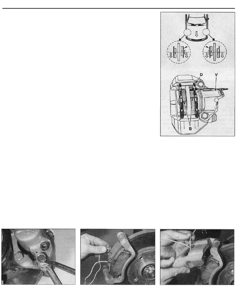
2 Trace the brake pad wear sensor wiring
back from the pads, and disconnect it from
the wiring connector (see illustration). Note
the routing of the wiring, and free it from any
relevant retaining clips.
3 Push the piston into its bore by pulling the
caliper outwards.
4 There are two different types of front brake
caliper fitted to the models covered in this
manual. On 1124 cc and 1360 cc models,
Bendix calipers are fitted, whereas on all
4.7 Measuring brake pad friction material
thickness
4.5b . . . then slide out the retaining
p l a t e . . .
1580 cc and larger-engined models, Girling
calipers are used. Proceed as described
under the relevant sub-heading.
Bendix caliper
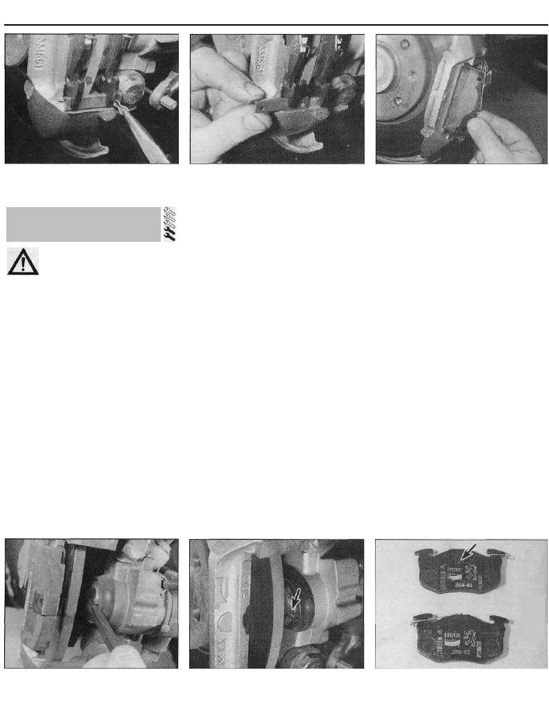
5 Using pliers, extract the small spring clip
from the pad retaining plate, and then slide
the plate out of the caliper (see illustrations).
6 Withdraw the pads from the caliper, then
make a note of the correct fitted position of
each anti-rattle spring, and remove the spring
from each pad (see illustration).
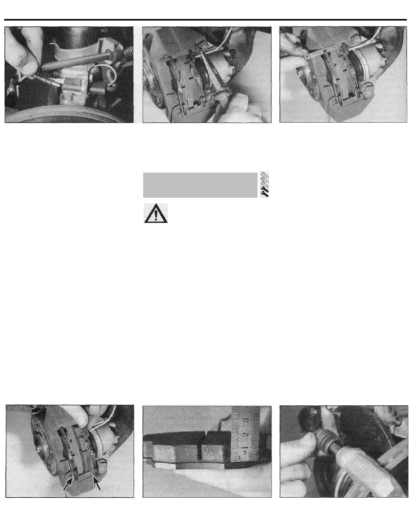
7 First measure the thickness of each brake
pad's friction material. If either pad is worn at
any point to the specified minimum thickness
or less, all four pads must be renewed (see
illustration). Also, the pads should be renewed
if any are fouled with oil or grease; there is no
satisfactory way of degreasing friction material,
once contaminated. If any of the brake pads
are worn unevenly, or are fouled with oil or
grease, trace and rectify the cause before
reassembly. New brake pads and spring kits
are available from Citroen dealers.
8 If the brake pads are still serviceable,
carefully clean them using a clean, fine wire
brush or similar, paying particular attention to
the sides and back of the metal backing. Clean
out the grooves in the friction material, and
pick out any large embedded particles of dirt
or debris. Carefully clean the pad locations in
the caliper body/mounting bracket.
9 Prior to fitting the pads, check that the
guide pins are free to slide easily in the caliper
body/mounting bracket, and check that the
4.9 While the caliper is removed, check
the condition of the guide pins and gaiters
- Girling caliper shown
Braking system 9•5
rubber guide pin gaiters are undamaged (see
illustration). Brush the dust and dirt from the
caliper and piston, but do not inhale it, as it is
injurious to health. Inspect the dust seal
around the piston for damage, and the piston
for evidence of fluid leaks, corrosion or
damage. If attention to any of these
components is necessary, refer to Section 10.
10 If new brake pads are to be fitted, the
caliper piston must be pushed back into the
cylinder to make room for them. Either use a
G-clamp or similar tool, or use suitable pieces
of wood as levers. Provided that the master
cylinder reservoir has not been overfilled with
hydraulic fluid, there should be no spillage,
but keep a careful watch on the fluid level
while retracting the piston. If the fluid level
rises above the "MAX" level line at any time,
the surplus should be syphoned off or ejected
via a plastic tube connected to the bleed
screw (see Section 2). Note: Do not syphon
the fluid by mouth, as it is poisonous; use a
syringe or an old poultry baster.
11 Fit the anti-rattle springs to the pads, so
that when the pads are installed in the caliper,
the spring end will be located at the opposite
end of the pad in relation to the pad retaining
plate.
12 Locate the pads in the caliper, ensuring
that the friction material of each pad is against
the brake disc, and check that the anti-rattle
spring ends are at the opposite end of the pad
to which the retaining plate is to be inserted.
Note that if the pads are installed correctly,
looking at the pads from the front of the
vehicle, the innermost pad groove must be
higher than the outer pad groove. Ensure the
pads are fitted correctly before proceeding
(see illustration).
13 Slide the retaining plate into place, and
install the new small spring clip at its inner
end. It may be necessary to file an entry
chamfer on the edge of the retaining plate, to
enable it to be fitted without difficulty.
14 Reconnect the brake pad wear sensor
wiring connectors, ensuring that the outer
wire is correctly routed through the anti-rattle
spring loops, and that both wires pass
through the loop of the bleed screw cap.
15 Depress the brake pedal repeatedly, until
the pads are pressed into firm contact with
the brake disc, and normal (non-assisted)
pedal pressure is restored.
16 Repeat the above procedure on the
remaining front brake caliper.
17 Refit the roadwheels, then lower the
vehicle to the ground and tighten the
roadwheel bolts to the specified torque setting.
18 Check the hydraulic fluid level as
described in Chapter 1.
Girling caliper
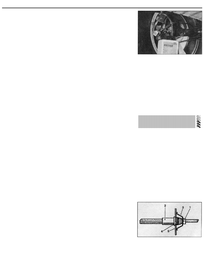
19 Slacken and remove the upper and lower
caliper guide pin bolts, using a slim open-ended
spanner to prevent the guide pin itself from
rotating (see illustration). Where possible, new
guide pin bolts should be used on refitting,
otherwise clean the old ones thoroughly.
20 With the guide pin bolts removed, lift the
caliper away from the brake pads and
mounting bracket, and tie it to the suspension
strut using a suitable piece of wire. Do not
allow the caliper to hang unsupported on the
flexible brake hose.
21 Withdraw the two brake pads from the
caliper mounting bracket, and examine them
as described above in paragraphs 7 to 10.
22 Install the pads in the caliper mounting
bracket, ensuring that the friction material of
each pad is against the brake disc (see
illustration).
23 Position the caliper over the pads, and
pass the pad warning sensor wiring through
the caliper aperture and underneath the
retaining clip (see illustration). If the threads
of the guide pin bolts are not already coated
with locking compound, apply a suitable
thread-locking compound to them. Press the
caliper into position, then install the guide pin
bolts, tightening them to the specified torque
setting while retaining the guide pins with an
open-ended spanner.
24 Reconnect the brake pad wear sensor
wiring connectors, ensuring that the wiring is
correctly routed through the loop of the
caliper bleed screw cap.
25 Depress the brake pedal repeatedly, until
the pads are pressed into firm contact with
the brake disc, and normal (non-assisted)
pedal pressure is restored.
4.12 Correct fitting of brake pads - Bendix
caliper
B Grooves
D Pad retaining plate spring clip
V Bleed screw
26 Repeat the above procedure on the
remaining front brake caliper.
27 Refit the roadwheels, then lower the
vehicle to the ground and tighten the
roadwheel bolts to the specified torque
setting.
28 Check the hydraulic fluid level as
described in Chapter 1.
All calipers
29 New pads will not give full braking
efficiency until they have bedded in. Be
prepared for this, and avoid hard braking as
far as possible for the first hundred miles or so
after pad renewal.
4.19 On the Girling caliper, retain the
guide pin with an open-ended spanner
while slackening the guide pin bolt
4.22 Ensure that the brake pads are fitted
the correct way around, with friction
material facing the disc . . .
4.23 . . . then refit the caliper, feeding the
pad wiring through the caliper aperture
FRONT
9•6 Braking system
5.2a Extract the spring clip . . .
5.2b . . . then slide out the pad retaining
p l a t e . . .
5.3 . . . and withdraw the brake pads from
the caliper
5 Rear brake pads - renewal
Warning: Renew both sets of rear
brake pads at the same time -
never renew the pads on only
one wheel, as uneven braking may result.
Note that the dust created by wear of the
pads may contain asbestos, which is a
health hazard. Never blow it out with
compressed air, and don't inhale any of it.
An approved filtering mask should be worn
when working on the brakes. DO NOT use
petrol or petroleum-based solvents to
clean brake parts; use brake cleaner or
methylated spirit only.
1 Chock the front wheels, then jack up the
rear of the vehicle and support it on axle
stands. Remove the rear wheels.
2 Extract the small spring clip from the pad
retaining plate, and then slide the plate out of
the caliper (see illustrations). Discard the
spring clip - a new one must be used on
refitting.
3 Using pliers if necessary, withdraw both the
inner and outer pads from the caliper (see
illustration). Make a note of the correct fitted
position of the anti-rattle springs, and remove
the springs from each pad.
4 First measure the thickness of the friction
material of each brake pad. If either pad is
worn at any point to the specified minimum
thickness or less, all four pads must be
renewed. Also, the pads should be renewed if
any are fouled with oil or grease; there is no
satisfactory way of degreasing friction
material, once contaminated. If any of the
brake pads are worn unevenly, or fouled with
oil or grease, trace and rectify the cause
before reassembly. New brake pads and
spring kits are available from Citroen dealers.
5 If the brake pads are still serviceable,
carefully clean them using a clean, fine wire
brush or similar, paying particular attention to
the sides and back of the metal backing.
Clean out the grooves in the friction material,
and pick out any large embedded particles of
dirt or debris. Carefully clean the pad
locations in the caliper body/mounting
bracket.
6 Prior to fitting the pads, check that the
guide sleeves are free to slide easily in the
caliper body, and check that the rubber guide
sleeve gaiters are undamaged. Brush the dust
and dirt from the caliper and piston, but do
not inhale it, as it is injurious to health. Inspect
the dust seal around the piston for damage,
and the piston for evidence of fluid leaks,
corrosion or damage. If attention to any of
these components is necessary, refer to
Section 11,
7 If new brake pads are to be fitted, it will be
necessary to retract the piston fully into the
5.7 Retract the piston using a square-
section b a r . . .
5.8 . . . and position the piston so that its
slot (arrowed) is horizontal to the ground
caliper bore, by rotating it in a clockwise
direction. This can be achieved using a
suitable square-section bar, such as the shaft
of a screwdriver, which locates snugly in the
caliper piston slots (see illustration).
Provided that the master cylinder reservoir
has not been overfilled with hydraulic fluid,
there should be no spillage, but keep a careful
watch on the fluid level while retracting the
piston. If the fluid level rises above the "MAX"
level line at any time, the surplus should be
syphoned off, or ejected via a plastic tube
connected to the bleed screw (see Section 2).
Note: Do not syphon the fluid by mouth, as it
is poisonous; use a syringe or an old poultry
baster.
8 Position the caliper piston so that its piston
slot is horizontal; this is necessary to ensure
that the lug on the inner pad will locate with
the caliper piston slot on installation (see
illustration).
9 The brake pad with the lug on its backing
plate is the inner pad. Refit the anti-rattle
springs to the pads, so that when the pads
are installed in the caliper, the spring end will
be located at the opposite end of the pad, in
relation to the pad retaining plate (see
illustration).
10 Locate the outer brake pad in the caliper
body, ensuring that its friction material is
against the brake disc. Slide the inner pad into
position in the caliper, ensuring that the lug on
5.9 Inner brake pad can be identified by its
locating lug (arrowed). Note the correct
fitted positions of the anti-rattle springs
Braking system 9•7
5.10 Install the inner pad, ensuring its
locating lug is correctly engaged in the
piston slot
its backing plate is aligned with the slot in the
caliper piston (see illustration).
11 Ensure that the anti-rattle spring ends on
both pads are correctly positioned, then slide
the retaining plate into place, and secure it in
position with a new spring clip. It may be
necessary to file an entry chamfer on the edge
of the retaining plate, to enable it to be fitted
without difficulty.
12 Depress the brake pedal repeatedly until
the pads are pressed into firm contact with
the brake disc, and normal (non-assisted)
pedal pressure is restored. Check that the
inner pad lug is correctly engaged with one of
the caliper piston slots.
13 Repeat the above procedure on the
remaining rear brake caliper.
14 Check the handbrake cable adjustment as
described in Section 17, then refit the
roadwheels and lower the vehicle to the
ground. Tighten the roadwheel bolts to the
specified torque setting.
15 Check the hydraulic fluid level as
described in Chapter 1.
16 Be prepared for reduced braking
efficiency while the new pads bed in, as
described at the end of the previous Section.
Warning: Brake shoes must be
renewed on both rear wheels at
the same time - never renew the
shoes on only one wheel, as
uneven braking may result. Also, the dust
created by wear of the shoes may contain
asbestos, which is a health hazard. Never
blow it out with compressed air, and don't
inhale any of it. An approved filtering mask
should be worn when working on the
brakes. DO NOT use petrol or petroleum-
based solvents to clean brake parts; use
brake cleaner or methylated spirit only.
1 Remove the brake drum as described in
Section 9.
2 Working carefully, and taking the necessary
precautions, remove all traces of brake dust
from the brake drum, backplate and shoes.
3 Measure the thickness of the friction
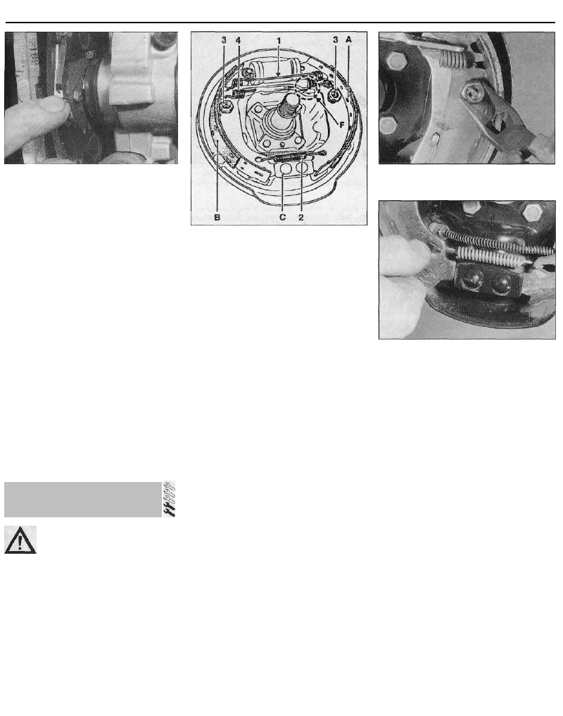
6.6b Removing a shoe retainer spring cup
6.6a Correct fitted positions of the Bendix
rear brake components
A Leading shoe
B Trailing shoe
C Lower pivot point
F Adjuster strut mechanism
1 Upper return spring
2 Lower return spring
3 Retaining pin, spring and spring cup
4 Adjuster strut-to-trailing shoe spring
material of each brake shoe at several points;
if either shoe is worn at any point to the
specified minimum thickness or less, all four
shoes must be renewed as a set. The shoes
should also be renewed if any are fouled with
oil or grease; there is no satisfactory way of
degreasing friction material, once
contaminated.
4 If any of the brake shoes are worn unevenly,
or fouled with oil or grease, trace and rectify
the cause before reassembly.
5 To renew the brake shoes, proceed as
described under the relevant sub-heading.
Bendix brake shoes
6 Using a pair of pliers, remove the shoe
retainer spring cups by depressing and
turning them through 90° (see illustrations).
With the cups removed, lift off the springs and
withdraw the retainer pins.
7 Ease the shoes out one at a time from the
lower pivot point, to release the tension of the
return spring, then disconnect the lower return
spring from both shoes (see illustration).
8 Ease the upper end of both shoes out from
their wheel cylinder locations, taking care not
to damage the wheel cylinder seals, and
disconnect the handbrake cable from the
trailing shoe. The brake shoe and adjuster
strut assembly can then be manoeuvred out
of position and away from the backplate. Do
not depress the brake pedal until the brakes
are reassembled; wrap a strong elastic band
around the wheel cylinder pistons to retain
them.
9 With the shoe and adjuster strut assembly
on a bench, make a note of the correct fitted
6.7 On Bendix rear brake shoes, ease the
shoes out of the lower pivot point, and
disconnect the lower return spring
positions of the springs and adjuster strut, to
use as a guide on reassembly. Release the
handbrake lever stop-peg (if not already
done), then carefully detach the adjuster strut
bolt retaining spring from the leading shoe.
Disconnect the upper return spring, then
detach the leading shoe and return spring
from the trailing shoe and strut assembly.
Unhook the spring securing the adjuster strut
to the trailing shoe, and separate the two.
10 If genuine Citroen brake shoes are being
installed, it will be necessary to remove the
handbrake lever from the original trailing shoe,
and install it on the new shoe. Secure the
lever in position with a new retaining clip. All
return springs should be renewed, regardless
of their apparent condition; spring kits are
also available from Citroen dealers.
11 Withdraw the adjuster bolt from the strut,
and carefully examine the assembly for signs
of wear or damage. Pay particular attention to
the threads of the adjuster bolt and the
knurled adjuster wheel, and renew if
necessary. Note that left-hand and right-hand
struts are not interchangeable - they are
marked " G " (gauche) and " D " (droit)
respectively. Also note that the strut adjuster
bolts are not interchangeable; the left-hand
strut bolt has a left-handed thread, and the
right-hand bolt a right-handed thread.
12 Ensure the components on the end of the
strut are correctly positioned, then apply a
little high-melting-point grease to the threads
6 Rear brake shoes - renewal
9•8 Braking system
6.12 Correct fitted position of Bendix
adjuster strut components
of the adjuster bolt (see illustration). Screw
the adjuster wheel onto the bolt until only a
small gap exists between the wheel and the
head of the bolt, then install the bolt in the
strut.
13 Fit the adjuster strut retaining spring to
the trailing shoe, ensuring that the shorter
hook of the spring is engaged with the shoe.
Attach the adjuster strut to the spring end,
then ease the strut into position in its slot in
the trailing shoe.
14 Engage the upper return spring with the
trailing shoe, then hook the leading shoe onto
the other end of the spring, and lever the
leading shoe down until the adjuster bolt head
is correctly located in its groove. Once the
bolt is correctly located, hook its retaining
spring into the slot on the leading shoe.
15 Peel back the rubber protective caps, and
check the wheel cylinder for fluid leaks or
other damage; check that both cylinder
pistons are free to move easily. Refer to
Section 12, if necessary, for information on
wheel cylinder renewal.
16 Prior to installation, clean the backplate,
and apply a thin smear of high-temperature
brake grease or anti-seize compound to all
those surfaces of the backplate which bear on
the shoes, particularly the wheel cylinder
pistons and lower pivot point (see
illustration). Do not allow the lubricant to foul
the friction material.
17 Ensure the handbrake lever stop-peg is
correctly located against the edge of the
trailing shoe, and remove the elastic band
fitted to the wheel cylinder.
18 Manoeuvre the shoe and strut assembly
into position on the vehicle, and locate the
upper end of both shoes with the wheel
cylinder pistons. Attach the handbrake cable
to the trailing shoe lever. Fit the lower return
spring to both shoes, and ease the shoes into
position on the lower pivot point.
19 Tap the shoes to centralise them with the
backplate, then refit the shoe retainer pins
and springs, and secure them in position with
the spring cups.
20 Using a screwdriver, turn the strut
adjuster wheel to expand the shoes until the
brake drum just slides over the shoes.
6.16 Apply a little high-melting-point
grease to the shoe contact points on the
backplate
21 Refit the brake drum as described in
Section 9.
22 Repeat the above procedure on the
remaining rear brake.
23 Once both sets of rear shoes have been
renewed, adjust the lining-to-drum clearance
by repeatedly depressing the brake pedal.
Whilst depressing the pedal, have an
assistant listen to the rear drums, to check
that the adjuster strut is functioning correctly;
if so, a clicking sound will be emitted by the
strut as the pedal is depressed.
24 Check and, if necessary, adjust the
handbrake as described in Section 17.
25 On completion, check the hydraulic fluid
level as described in Chapter 1.
Girling brake shoes
26 Make a note of the correct fitted positions
of the springs and adjuster strut, to use as a
guide on reassembly.
27 Carefully unhook both the upper and
lower return springs, and remove them from
the brake shoes.
28 Using a pair of pliers, remove the leading
shoe retainer spring cup by depressing it and
turning through 90°. With the cup removed, lift
off the spring, then withdraw the retainer pin
and remove the shoe from the backplate.
Unhook the adjusting lever spring, and
remove it from the leading shoe.
29 Detach the adjuster strut, and remove it
from the trailing shoe.
30 Remove the trailing shoe retainer spring
cup, spring and pin as described above, then
detach the handbrake cable and remove the
shoe from the vehicle. Do not depress the
brake pedal until the brakes are reassembled;
wrap a strong elastic band around the wheel
cylinder pistons to retain them.
31 If genuine Citroen brake shoes are being
installed, it will be necessary to remove the
adjusting lever from the original leading shoe,
and install it on the new shoe. All return
springs should be renewed, regardless of their
apparent condition; spring kits are also
available from Citroen dealers.
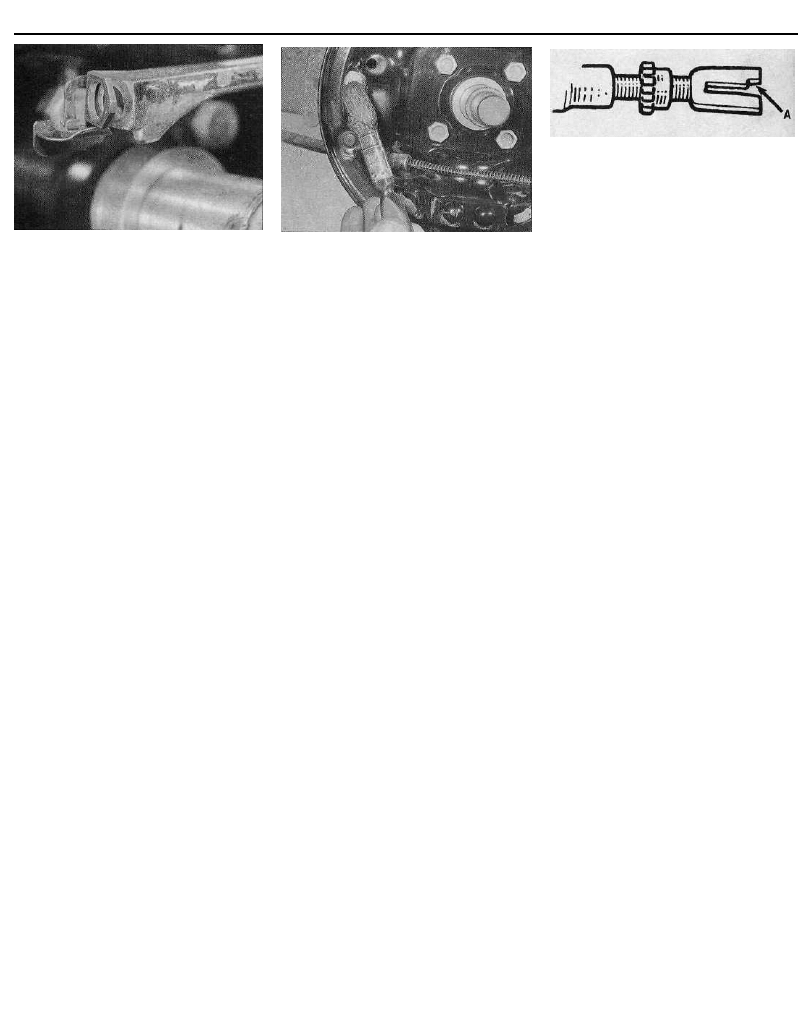
32 Withdraw the forked end from the strut,
and carefully examine the assembly for signs
of wear or damage. Pay particular attention to
6.37 On Girling rear brake shoes, adjuster
strut fork cut-out (A) must engage with
leading shoe adjusting lever on refitting
the threads and the knurled adjuster wheel,
and renew if necessary. Note that left-hand
and right-hand struts are not interchangeable;
the left-hand fork has a right-handed thread,
and the right-hand fork a left-handed thread.
33 Peel back the rubber protective caps, and
check the wheel cylinder for fluid leaks or
other damage; check that both cylinder
pistons are free to move easily. Refer to
Section 12, if necessary, for information on
wheel cylinder renewal.
34 Prior to installation, clean the backplate,
and apply a thin smear of high-temperature
brake grease or anti-seize compound to all
those surfaces of the backplate which bear on
the shoes, particularly the wheel cylinder
pistons and lower pivot point. Do not allow
the lubricant to foul the friction material.
35 Ensure the handbrake lever stop-peg is
correctly located against the edge of the
trailing shoe, and remove the elastic band
fitted to the wheel cylinder.
36 Locate the upper end of the trailing shoe
in the wheel cylinder piston, then refit the
retainer pin and spring, and secure it in
position with the spring cup. Connect the
handbrake cable to the lever.
37 Screw in the adjuster wheel until the
minimum strut length is obtained, then hook
the strut into position on the trailing shoe.
Rotate the adjuster strut forked end, so that
the cut-out of the fork will engage with the
leading shoe adjusting lever once the shoe is
installed (see illustration).
38 Fit the spring to the leading shoe
adjusting lever, so that the shorter hook of the
spring engages with the lever.
39 Slide the leading shoe assembly into
position, ensuring that it is correctly engaged
with the adjuster strut fork, and that the fork
cut-out is engaged with the adjusting lever.
Ensure the upper end of the shoe is located in
the wheel cylinder piston, then secure the
shoe in position with the retainer pin, spring
and spring cup.
40 Install the upper and lower return springs,
then tap the shoes to centralise them with the
backplate.
41 Using a screwdriver, turn the strut
adjuster wheel to expand the shoes until the
brake drum just slides over the shoes.
42 Refit the brake drum as described in
Section 9.
43 Repeat the above procedure on the
remaining rear brake.
44 Once both sets of rear shoes have been
renewed, adjust the lining-to-drum clearance
Braking system 9•9
7.3 Using a micrometer to measure disc
thickness
by repeatedly depressing the brake pedal.
Whilst depressing the pedal, have an
assistant listen to the rear drums, to check
that the adjuster strut is functioning correctly;
if so, a clicking sound will be emitted by the
strut as the pedal is depressed.
45 Check and, if necessary, adjust the
handbrake as described in Section 17.
46 On completion, check the hydraulic fluid
level as described in Chapter 1.
All shoes
47 Be prepared for reduced braking
efficiency while the new shoes bed in, as
described at the end of Section 4.
Note: Before starting work, refer to the note at
the beginning of Section 4 concerning the
dangers of asbestos dust.
Inspection
Note: If either disc requires renewal, BOTH
should be renewed at the same time, to
ensure even and consistent braking. New
brake pads should also be fitted.
1 Apply the handbrake, then jack up the front
of the car and support it on axle stands.
Remove the appropriate front roadwheel.
2 Slowly rotate the brake disc so that the full
area of both sides can be checked; remove
7.4 Checking disc run-out using a dial
gauge
the brake pads if better access is required to
the inboard surface. Ught scoring is normal in
the area swept by the brake pads, but if heavy
scoring or cracks are found, the disc must be
renewed.
3 It is normal to find a lip of rust and brake
dust around the disc's perimeter; this can be
scraped off if required. If, however, a lip has
formed due to excessive wear of the brake
pad swept area, then the disc's thickness
must be measured using a micrometer (see
illustration). Take measurements at several
places around the disc, at the inside and
outside of the pad swept area; if the disc has
worn at any point to the specified minimum
thickness or less, the disc must be renewed.
4 If the disc is thought to be warped, it can be
checked for run-out. Either use a dial gauge
mounted on any convenient fixed point, while
the disc is slowly rotated, or use feeler gauges
to measure (at several points all around the
disc) the clearance between the disc and a
fixed point, such as the caliper mounting
bracket (see illustration). If the measure-
ments obtained are at the specified maximum
or beyond, the disc is excessively warped,
and must be renewed; however, it is worth
checking first that the hub bearing is in good
condition (Chapters 1 and/or 10). Also try the
effect of removing the disc and turning it
through 180°, to reposition it on the hub; if the
run-out is still excessive, the disc must be
renewed.
5 Check the disc for cracks, especially
7.7a Undo the two mounting bolts . . .
around the wheel bolt holes, and any other
wear or damage, and renew if necessary.
Removal
6 On 1124 cc and 1360 cc models, remove
the brake pads as described in Section 4,
paragraphs 1 to 6.
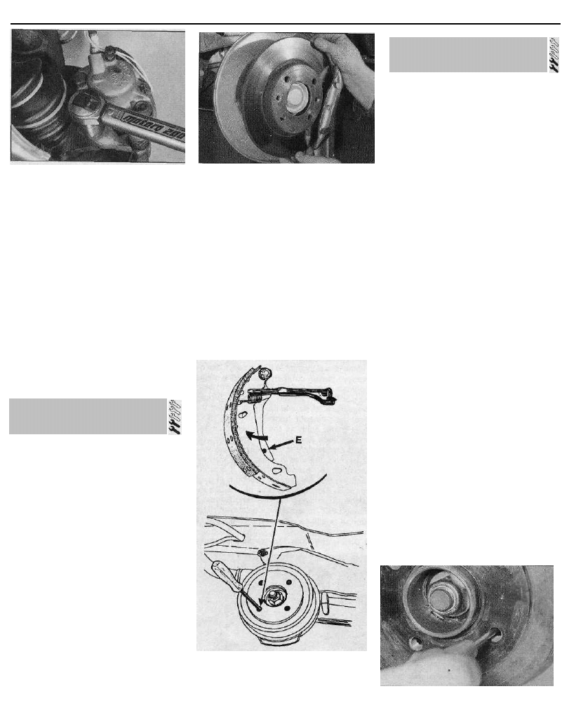
7 On all 1580 cc and larger-engined models,
unscrew the two bolts securing the brake
caliper to the swivel hub, and discard them -
new bolts must be used on refitting. Slacken
and remove the bolt securing the wiring
retaining bracket to the swivel hub, then slide
the caliper assembly off the disc. Using a
piece of wire or string, tie the caliper to the
front suspension coil spring, to avoid placing
any strain on the hydraulic brake hose (see
illustrations).
8 Use chalk or paint to mark the relationship
of the disc to the hub, then remove the screws
securing the brake disc to the hub, and
remove the disc (see illustration). If it is tight,
lightly tap its rear face with a hide or plastic
mallet.
Refitting
9 Refitting is the reverse of the removal
procedure, noting the following points:
(a) Ensure that the mating surfaces of the
disc and hub are clean and flat.
(b) Align (if applicable) the marks made on
removal, and securely tighten the disc
retaining screws.
(c) If a new disc has been fitted, use a
7.7b . . . then slide the caliper assembly off
the disc . . .
7.7c . . . and tie it to the suspension strut, to
avoid placing any strain on the flexible hose
7.8 Undo the two retaining screws and
remove the disc
7 Front brake disc -
inspection, removal and refitting
9•10 Braking system
7.9 On refitting, tighten the caliper mounting
bolts to the specified torque setting
suitable solvent to wipe any preservative
coating from the disc, before refitting the
caliper.
(d) On 1580 cc and larger-engined models, if
the threads of the newcaliper mounting
bolts are not already pre-coated with
locking compound, apply a suitable
locking compound to them. Refit the
caliper, and tighten the mounting bolts to
the specified torque setting (see
illustration).
(e) On 1124 cc and 1360 cc models, refit the
pads as described in paragraphs 12 to 18
of Section 4.
(f) Refit the roadwheel, then lower the
vehicle to the ground and tighten the
roadwheel bolts to the specified torque.
On completion, repeatedly depress the
brake pedal until normal (non-assisted)
pedal pressure returns.
Note: Before starting work, refer to the note at
the beginning of Section 5 concerning the
dangers of asbestos dust.
Inspection
Note: If either disc requires renewal, BOTH
should be renewed at the same time, to
ensure even and consistent braking. New
brake pads should be fitted also.
1 Firmly chock the front wheels, then jack up
the rear of the car and support it on axle
stands. Remove the appropriate rear
roadwheel.
2 Inspect the disc as described in Section 7.
Removal
3 Remove the brake pads as described in
Section 5.
4 Use chalk or paint to mark the relationship
of the disc to the hub, then remove the screw
securing the brake disc to the hub, and
remove the disc (see illustration). If it is tight,
lightly tap its rear face with a hide or plastic
mallet.
Refitting
5 Refitting is the reverse of the removal
procedure, noting the following points:
8.4 Removing the rear brake disc
(a) Ensure that the mating surfaces of the
disc and hub are clean and flat.
(b) Align (if applicable) the marks made on
removal, and securely tighten the disc
retaining screws.
(c) If a new disc has been fitted, use a
suitable solvent to wipe any preservative
coating from the disc, before refitting the
caliper.
(d) Refit the brake pads as described in
Section 5.
(e) Refit the roadwheel, then lower the
vehicle to the ground and tighten the
roadwheel bolts to the specified torque.
9.6a Using a screwdriver inserted through
the brake drum to release the handbrake
operating lever
E Handbrake operating lever stop-peg
location
Note: Before starting work, refer to the note at
the beginning of Section 6 concerning the
dangers of asbestos dust.
Removal
1 Chock the front wheels, then jack up the
rear of the vehicle and support it on axle
stands. Remove the appropriate rear wheel.
2 Using a hammer and a large flat-bladed
screwdriver, carefully tap and prise the cap
out of the centre of the brake drum. Discard
the cap - a new one must be used on refitting.
Using a hammer and chisel, tap up the staking
securing the hub retaining nut to the groove in
the stub axle.
3 Using a socket and long bar, slacken and
remove the rear hub nut, and withdraw the
thrustwasher. Discard the hub nut - a new nut
must used on refitting.
4 It should now be possible to withdraw the
brake drum and hub bearing assembly from the
stub axle by hand. It may be difficult to remove
the drum due to the tightness of the hub
bearing on the stub axle, or due to the brake
shoes binding on the inner circumference of the
drum. If the bearing is tight, tap the periphery of
the drum using a hide or plastic mallet, or use a
universal puller, secured to the drum with the
wheel bolts, to pull it off. If the brake shoes are
binding, first check that the handbrake is fully
released, then proceed as follows.
5 Referring to Section 17 for further
information, fully slacken the handbrake cable
adjuster nut, to obtain maximum free play in
the cable.
6 Insert a screwdriver through one of the
wheel bolt holes in the brake drum, so that it
contacts the handbrake operating lever on the
trailing brake shoe. Push the lever until the
stop-peg slips behind the brake shoe web,
allowing the brake shoes to retract fully (see
illustrations). The brake drum can now be
withdrawn, and the seal slid off the stub axle.
Inspection
Note: If either drum requires renewal, BOTH
should be renewed at the same time, to
ensure even and consistent braking. New
brake shoes should also be fitted.
9.6b Releasing the handbrake operating
lever
9 Rear brake drum -
removal, inspection and refitting
8 Rear brake disc -
inspection, removal and refitting
Braking system 9•11
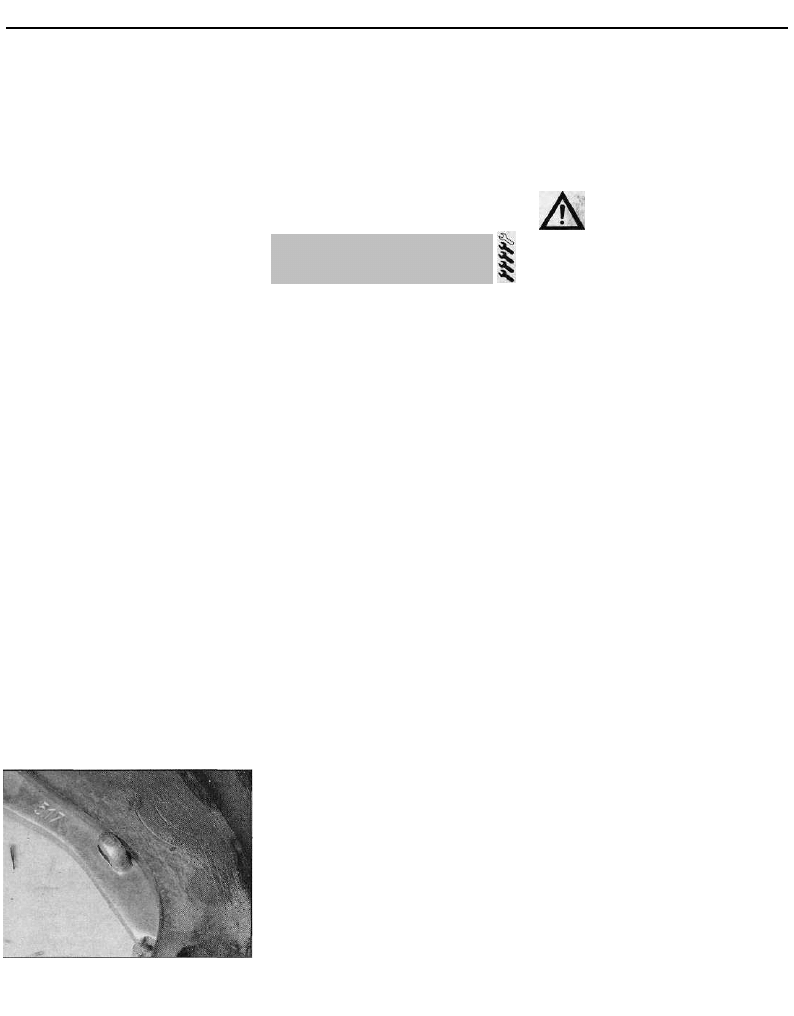
7 Working carefully, remove all traces of
brake dust from the drum, but avoid inhaling
the dust, as it is injurious to health.
8 Clean the outside of the drum, and check it
for obvious signs of wear or damage, such as
cracks around the roadwheel bolt holes;
renew the drum if necessary.
9 Examine carefully the inside of the drum.
Light scoring of the friction surface is normal,
but if heavy scoring is found, the drum must
be renewed. It is usual to find a lip on the
drum's inboard edge which consists of a
mixture of rust and brake dust; this should be
scraped away, to leave a smooth surface
which can be polished with fine (120- to 150-
grade) emery paper. If, however, the lip is due
to the friction surface being recessed by
excessive wear, then the drum must be
renewed.
10 If the drum is thought to be excessively
worn, or oval, its internal diameter must be
measured at several points using an internal
micrometer. Take measurements in pairs, the
second at right-angles to the first, and
compare the two, to check for signs of ovality.
Provided that it does not enlarge the drum to
beyond the specified maximum diameter, it
may be possible to have the drum refinished
by skimming or grinding; if this is not possible,
the drums on both sides must be renewed.
Note that if the drum is to be skimmed, BOTH
drums must be refinished, to maintain a
consistent internal diameter on both sides.
Refitting
11 If a new brake drum is to be installed, use
a suitable solvent to remove any preservative
coating that may have been applied to its
interior. Note that it may also be necessary to
shorten the adjuster strut length, by rotating
the strut wheel, to allow the drum to pass over
the brake shoes.
12 Ensure that the handbrake lever stop-peg
is correctly repositioned against the edge of
the brake shoe web (see illustration), then
apply a smear of clean engine oil to the stub
axle, and slide on the seal and brake drum.
13 Fit the thrustwasher and new hub nut, and
tighten the hub nut to the specified torque.
Stake the nut firmly into the groove on the
stub axle, to secure it in position, then tap the
new hub cap into place in the centre of the
brake drum.
14 Depress the footbrake several times to
operate the self-adjusting mechanism.
15 Repeat the above procedure on the
remaining rear brake assembly (where
necessary), then check and, if necessary,
adjust the handbrake cable as described in
Section 17.
16 On completion, refit the roadwheels), then
lower the vehicle to the ground and tighten the
wheel bolts to the specified torque.
10 Front brake caliper -
removal, overhaul and refitting
9.12 Check that the handbrake lever stop-
peg is correctly positioned against the
shoe edge
Note: Before starting work, refer to the note at
the beginning of Section 2 concerning the
dangers of hydraulic fluid, and to the warning
at the beginning of Section 4 concerning the
dangers of asbestos dust.
Removal
1 Apply the handbrake, then jack up the front
of the vehicle and support it on axle stands.
Remove the appropriate roadwheel.
2 Minimise fluid loss by first removing the
master cylinder reservoir cap, and then
tightening it down onto a piece of polythene,
to obtain an airtight seal. Alternatively, use a
brake hose clamp, a G-clamp or a similar tool
to clamp the flexible hose.
Bendix caliper -1124 cc and 1360 cc
models
3 Remove the brake pads as described in
Section 4.
4 Clean the area around the union, then
loosen the brake hose union nut.
5 Slacken the two bolts securing the caliper
assembly to the swivel hub and remove them
along with the mounting plate, noting which
way around the plate is fitted. Lift the caliper
assembly away from the brake disc, and
unscrew it from the end of the brake hose.
Girling caliper -1580 cc and larger-
engined models
6 Clean the area around the union, then
loosen the brake hose union nut. Disconnect
the pad wear warning sensor wiring from the
connector, and free it from any relevant
retaining clips.
7 Slacken and remove the upper and lower
caliper guide pin bolts, using a slim open-
ended spanner to prevent the guide pin itself
from rotating. Discard the guide pin bolts -
new bolts must be used on refitting. With the
guide pin bolts removed, lift the caliper away
from the brake disc, then unscrew the caliper
from the end of the brake hose. Note that the
brake pads need not be. disturbed, and can be
left in position in the caliper mounting bracket.
Overhaul
8 With the caliper on the bench, wipe away all
traces of dust and dirt, but avoid inhaling the
dust, as it is injurious to health.
9 Where necessary, use a small flat-bladed
screwdriver to carefully prise the dust seal
retaining clip out of the caliper bore.
10 Withdraw the partially-ejected piston from
the caliper body, and remove the dust seal.
The piston can be withdrawn by hand, or if
necessary pushed out by applying
compressed air to the brake hose union hole.
Only low pressure should be required, such as
is generated by a foot pump.
Caution: The piston may be
ejected with some force.
11 Using a small screwdriver, extract the
piston hydraulic seal, taking great care not to
damage the caliper bore.
12 Withdraw the guide sleeves/pins from the
caliper body/mounting bracket (as
applicable), and remove the rubber gaiters.
13 Thoroughly clean all components, using
only methylated spirit, isopropyl alcohol or
clean hydraulic fluid as a cleaning medium.
Never use mineral-based solvents such as
petrol or paraffin, as they will attack the
hydraulic system's rubber components. Dry
the components immediately, using
compressed air or a clean, lint-free cloth. Use
compressed air to blow clear the fluid
passages.
14 Check all components, and renew any
that are worn or damaged. Check particularly
the cylinder bore and piston; these should be
renewed (note that this means the renewal of
the complete body assembly) if they are
scratched, worn or corroded in any way.
Similarly check the condition of the guide
sleeves/pins and their bores in the caliper
body/mounting bracket (as applicable); both
sleeves/pins should be undamaged and
(when cleaned) a reasonably tight sliding fit in
the body/mounting bracket bores. If there is
any doubt about the condition of any
component, renew it.
15 If the assembly is fit for further use, obtain
the appropriate repair kit; the components are
available from Citroen dealers in various
combinations.
16 Renew all rubber seals, dust covers and
caps disturbed on dismantling as a matter of
course; these should never be re-used.
17 On reassembly, ensure that all
components are absolutely clean and dry.
18 Soak the piston and the new piston (fluid)
seal in clean hydraulic fluid. Smear clean fluid
on the cylinder bore surface.
19 Fit the new piston (fluid) seal, using only
your fingers (no tools) to manipulate it into the
cylinder bore groove. Fit the new dust seal to
the piston, and refit the piston to the cylinder
bore using a twisting motion; ensure that the
piston enters squarely into the bore. Press the
piston fully into the bore, then press the dust
seal into the caliper body.
20 Where fitted, install the dust seal retaining
clip, ensuring that it is correctly seated in the
caliper groove.
21 Apply the grease supplied in the repair kit,
9•12 Braking system
or a good quality high-temperature brake
grease or anti-seize compound, to the guide
sleeves/pins. Fit the guide sleeves/pins to the
caliper body/mounting bracket, and fit the
new rubber gaiters, ensuring that they are
correctly located in the grooves on both the
sleeve/pin and body/mounting bracket (as
applicable).
Refitting
Bendix caliper -1124 cc and 1360 cc
models
22 Screw the caliper fully onto the flexible
hose union, then position the caliper over the
brake disc.
23 If the threads of the new caliper mounting
bolts are not already pre-coated with locking
compound, apply a suitable locking
compound to them. Refit the bolts along with
the mounting plate, ensuring that the plate is
fitted so that its bend curves away from the
caliper body. With the plate correctly
positioned, tighten the caliper bolts to the
specified torque.
24 Securely tighten the brake hose union nut,
then refit the brake pads as described in
Section 4.
25 Remove the brake hose clamp or
polythene, as applicable, and bleed the
hydraulic system as described in Section 2.
Note that, providing the precautions
described were taken to minimise brake fluid
loss, it should only be necessary to bleed the
relevant front brake.
26 Refit the roadwheel, then lower the
vehicle to the ground and tighten the
roadwheel bolts to the specified torque.
Girling caliper -1580 cc and larger-
engined models
27 Screw the caliper body fully onto the
flexible hose union, then check that the brake
pads are still correctly fitted in the caliper
mounting bracket.
28 Position the caliper over the pads, and
pass the pad warning sensor wiring through
the caliper aperture. If the threads of the new
guide pin bolts are not already pre-coated
with locking compound, apply a suitable
locking compound to them. Fit the new lower
guide pin bolt, then press the caliper into
position and fit the new upper guide pin bolt.
Securely tighten both the guide pin bolts,
while retaining the guide pin with an open-
ended spanner.
29 Reconnect the brake pad wear sensor
wiring connectors, ensuring that the wiring is
correctly routed through the loop of the
caliper bleed screw cap.
30 Tighten the brake hose union nut
securely, then remove the brake hose clamp
or polythene, where fitted, and bleed the
hydraulic system as described in Section 2.
Note that, providing the precautions
described were taken to minimise brake fluid
loss, it should only be necessary to bleed the
relevant front brake.
31 Depress the brake pedal repeatedly, until
the pads are pressed into firm contact with
the brake disc, and normal (non-assisted)
pedal pressure is restored.
32 Refit the roadwheel, then lower the
vehicle to the ground and tighten the
roadwheel bolts to the specified torque.
Note: Before starting work, refer to the note at
the beginning of Section 2 concerning the
dangers of hydraulic fluid, and to the warning
at the beginning of Section 5 concerning the
dangers of asbestos dust.
Removal
1 Chock the front wheels, then jack up the
rear of the vehicle and support on axle stands.
Remove the relevant rear wheel.
2 Remove the brake pads as described in
Section 5.
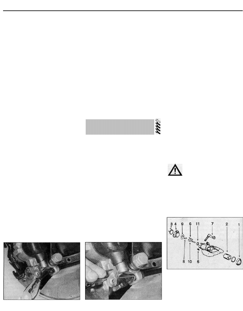
3 Ensure the handbrake is fully released, then
free the handbrake inner cable from the
caliper handbrake operating lever. Tap the
outer cable out of its bracket on the caliper
body (see illustrations).
4 Minimise fluid loss by first removing the
master cylinder reservoir cap, and then
tightening it down onto a piece of polythene,
to obtain an airtight seal. Alternatively, use a
brake hose clamp, a G-clamp or a similar tool
to clamp the flexible hose at the nearest
convenient point to the brake caliper.
5 Wipe away all traces of dirt around the
brake pipe union on the caliper, and slacken
the union nut.
6 Slacken the two bolts securing the caliper
assembly to the trailing arm, and remove them
along with the mounting plate, noting which
way around the plate is fitted. Lift the caliper
assembly away from the brake disc, and
unscrew it from the end of the brake hose.
Discard the caliper mounting bolts - they
should be renewed whenever *hey are
disturbed.
Overhaul
7 With the caliper on the bench, wipe away all
traces of dust and dirt, but avoid inhaling the
dust, as it is injurious to health.
8 Using a small screwdriver, carefully prise
out the dust seal from the caliper bore, taking
care not to damage the piston (see
illustration).
9 Remove the piston from the caliper bore by
rotating it in an anti-clockwise direction. This
can be achieved using a suitable square-
section bar, such as the shaft of a
screwdriver, which locates snugly in the
caliper piston slots. Once the piston turns
freely but does not come out any further, the
piston can be withdrawn by hand, or if
necessary pushed out by applying
compressed air to the union bolt hole. Only
low pressure should be required, such as is
generated by a foot pump.
Caution: The piston may be
ejected with some force.
10 Using a small screwdriver, extract the
piston hydraulic seal, taking care not to
damage the caliper bore.
11 Withdraw the guide sleeves from the
caliper body, and remove the guide sleeve
gaiters.
12 Inspect all the caliper components as
described in Section 10, paragraphs 13 to 17,
11.3a Disconnect the handbrake inner
cable from the caliper l e v e r . . .
11.3b . . . then tap the outer cable out from
the caliper body
11.8 Exploded view of the rear brake
caliper
1 Dust seal 6 Spring washers
2 Piston 7 Handbrake
3 Retaining clip operating lever
4 Handbrake 8 Plunger cam
mechanism dust 9 Return spring
cover 10 Adjusting screw
5 Circlip 11 Thrustwasher
11 Rear brake caliper -
removal, overhaul and refitting
Braking system 9•13
and renew as necessary, noting that the
inside of the caliper piston must not be
dismantled. If necessary, the handbrake
mechanism can be overhauled as described
in the following paragraphs; if it is not wished
to overhaul the handbrake mechanism,
proceed straight to paragraph 16.
13 Release the handbrake dust cover
retaining clip, and peel the cover away from
the rear of the caliper; make a note of the
correct fitted positions of the relative
components, to use as a guide on
reassembly. Remove the circlip from the base
of the operating lever shaft, then compress
the adjusting screw spring washers, and
withdraw the operating lever and dust cover
from the caliper body. With the lever
withdrawn, remove the return spring, plunger
cam, adjusting screw and spring washers,
and thrustwasher from the rear of the caliper
body. Using a suitable pin punch, carefully tap
the adjusting screw bush out of the caliper
body, and remove the O-ring.
14 Clean all the handbrake components in
methylated spirit, and examine them for wear.
If there is any sign of wear or damage, the
complete handbrake mechanism assembly
should be renewed; a kit is available from your
Citroen dealer. On reassembly, ensure that all
components are absolutely clean and dry.
15 Install the O-ring, then press the adjusting
screw bush into position in the rear of the
caliper body until its outer edge is flush with
the caliper body; if necessary, tap the bush
into position using a tubular drift. Fit the
thrustwasher, then install the adjusting screw
and spring washers, ensuring that the
washers are correctly positioned (see
illustration). Locate the plunger cam in the
end of the adjusting screw, and position the
return spring in the caliper housing. Fit the
new dust cover to the operating lever, then
compress the adjusting screw spring washers
11.15 Correct fitted positions of the rear
brake caliper handbrake mechanism
adjuster screw and associated
components
1 O-ring
2 Adjusting screw bush
3 Thrustwasher
4 Correct arrangement of spring washers
5 Adjusting screw
and insert the lever shaft through the caliper
body, ensuring that it is correctly engaged
with the return spring and plunger cam.
Secure the operating lever in position with the
circlip, then release the spring washers and
check the operation of the handbrake
mechanism. Apply a smear of high-melting-
point grease to the operating lever shaft and
adjusting screw, then slide the dust cover
over the caliper body, and secure it in position
with a cable tie.
16 Soak the piston and the new piston (fluid)
seal in clean hydraulic fluid. Smear clean fluid
on the cylinder bore surface.
17 Fit the new piston (fluid) seal, using only
the fingers to manipulate it into the cylinder
bore groove, and refit the piston assembly.
Turn the piston in a clockwise direction, using
the method employed on dismantling, until it
is fully retracted into the caliper bore.
18 Fit the dust seal to the caliper, ensuring
that it is correctly located in the caliper and
also the groove on the piston.
19 Apply the grease supplied in the repair kit,
or a good quality high-temperature brake
grease or anti-seize compound, to the guide
sleeves. Fit the guide sleeves to the caliper
body, and fit the new gaiters, ensuring that the
gaiters are correctly located in the grooves on
both the guide sleeve and caliper body.
Refitting
20 Screw the caliper fully onto the brake
hose, then position the caliper over the brake
disc. If the threads of the new caliper
mounting bolts are not already pre-coated
with locking compound, apply a suitable
locking compound to them. Install the new
caliper mounting bolts and the mounting
plate, noting that the mounting plate must be
fitted so that its bend curves away from the
caliper body. With the plate correctly
positioned, tighten the caliper bolts to the
specified torque.
21 Tighten the brake hose union securely,
then remove the clamp from the flexible brake
hose, or the polythene from the master
cylinder reservoir (as applicable).
22 Insert the handbrake cable through its
bracket on the caliper, and tap the outer cable
into position using a hammer and suitable pin
punch. Reconnect the inner cable to the
caliper operating lever.
23 Refit the brake pads as described in
Section 5.
24 Bleed the hydraulic system as described
in Section 2. Note that, providing the
precautions described were taken to minimise
brake fluid loss, it should only be necessary to
bleed the relevant rear brake.
25 Repeatedly apply the brake pedal until
normal (non-assisted) pedal pressure returns.
Check and if necessary adjust the handbrake
cable as described in Section 17.
26 Refit the roadwheel, then lower the
vehicle to the ground and tighten the wheel
bolts to the specified torque. On completion,
check the hydraulic fluid level as described in
Chapter 1.
12 Rear wheel cylinder -
removal and refitting
Note: Before starting work, refer to the note at
the beginning of Section 2 concerning the
dangers of hydraulic fluid, and to the warning
at the beginning of Section 6 concerning the
dangers of asbestos dust.
Removal
1 Remove the brake drum as described in
Section 9.
2 Using pliers, carefully unhook the upper
brake shoe return spring, and remove it from
both brake shoes. Pull the upper ends of the
shoes away from the wheel cylinder to
disengage them from the pistons.
3 Minimise fluid loss by first removing the
master cylinder reservoir cap, and then
tightening it down onto a piece of polythene,
to obtain an airtight seal. Alternatively, use a
brake hose clamp, a G-clamp or a similar tool
to clamp the flexible hose at the nearest
convenient point to the wheel cylinder (see
illustration).
4 Wipe away all traces of dirt around the
brake pipe union at the rear of the wheel
cylinder, and unscrew the union nut (see
illustration). Carefully ease the pipe out of the
wheel cylinder, and plug or tape over its end
to prevent dirt entry. Wipe off any spilt fluid
immediately.
12.3 To minimise fluid loss, fit a brake
hose clamp to the flexible hose
12.4 Using a brake pipe spanner to
unscrew the wheel cylinder union nut
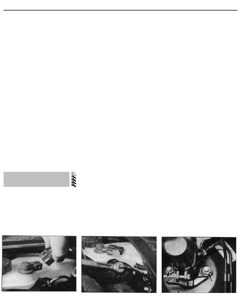
9•14 Braking system
5 Unscrew the two wheel cylinder retaining
bolts from the rear of the backplate, and
remove the cylinder, taking great care not to
allow surplus hydraulic fluid to contaminate
the brake shoe linings.
6 Note that it is not possible to overhaul the
cylinder, since no components are available
separately. If faulty, the complete wheel
cylinder assembly must be renewed.
Refitting
7 Ensure the backplate and wheel cylinder
mating surfaces are clean, then spread the
brake shoes and manoeuvre the wheel
cylinder into position.
8 Engage the brake pipe, and screw in the
union nut two or three turns to ensure that the
thread has started.
9 Insert the two wheel cylinder retaining
bolts, and tighten them securely. Now fully
tighten the brake pipe union nut.
10 Remove the clamp from the flexible brake
hose, or the polythene from the master
cylinder reservoir (as applicable).
11 Ensure the brake shoes are correctly
located in the cylinder pistons, then carefully
refit the brake shoe upper return spring, using
a screwdriver to stretch the spring into
position.
12 Refit the brake drum as described in
Section 9.
13 Bleed the brake hydraulic system as
described in Section 2. Providing suitable
precautions were taken to minimise loss of
fluid, it should only be necessary to bleed the
relevant rear brake.
13 Master cylinder - removal,
overhaul and refitting
Note: Before starting work, refer to the
warning at the beginning of Section 2
concerning the dangers of hydraulic fluid.
Removal
1 On left-hand-drive models, remove the
battery and battery tray as described in
Chapter 5.
2 On all models, remove the master cylinder
reservoir cap, and syphon the hydraulic fluid
from the reservoir. Note: Do not syphon the
fluid by mouth, as it is poisonous; use a
syringe or an old poultry baster. Alternatively,
open any convenient bleed screw in the
system, and gently pump the brake pedal to
expel the fluid through a plastic tube
connected to the screw (see Section 2).
Disconnect the wiring connector from the
brake fluid level sender unit (see illustration).
3 Wipe clean the area around the brake pipe
unions on the side of the master cylinder, and
place absorbent rags beneath the pipe unions
to catch any surplus fluid. Make a note of the
correct fitted positions of the unions, then
unscrew the union nuts and carefully
withdraw the pipes (see illustration). Plug or
tape over the pipe ends and master cylinder
orifices, to minimise the loss of brake fluid,
and to prevent the entry of dirt into the
system. Wash off any spilt fluid immediately
with cold water.
4 Slacken and remove the two nuts securing
the master cylinder to the vacuum servo unit,
then withdraw the unit from the engine
compartment (see illustration). Remove the
O-ring from the rear of the master cylinder,
and discard it.
Overhaul
5 Slacken the fluid reservoir retaining clamp
screw, then unhook the clamp and remove
the fluid reservoir and reservoir seals from the
master cylinder body.
6 Using a wooden dowel, press the piston
assembly into the master cylinder body, then
extract the circlip from the end of the master
cylinder bore.
7 Noting the order of removal, and the
direction of fitting of each component,
withdraw the washer, and the piston
assemblies with their springs and seals,
tapping the body on to a clean wooden
surface to dislodge them. If necessary, clamp
the master cylinder body in a vice (fitted with
soft jaw covers) and use compressed air
(applied through the secondary circuit fluid
port) to assist the removal of the secondary
piston assembly.
8 Thoroughly clean all components, using
only methylated spirit, isopropyl alcohol or
clean hydraulic fluid as a cleaning medium.
Never use mineral-based solvents such as
petrol or paraffin, as they will attack the
hydraulic system's rubber components. Dry
the components immediately, using
compressed air or a clean, lint-free cloth.
9 Check all components, and renew any that
are worn or damaged. Check particularly the
cylinder bores and pistons; the complete
assembly should be renewed if these are
scratched, worn or corroded. If there is any
doubt about the condition of the assembly or
of any of its components, renew it. Check that
the body's fluid passages are clear.
10 If the assembly is fit for further use, obtain
a repair kit from your Citroen dealer; the kit
consists of both piston assemblies and
springs, as well as a new circlip. Renew all
seals and sealing O-rings disturbed on
dismantling as a matter of course; these
should never be re-used.
11 On reassembly, soak the pistons and the
new seals in clean hydraulic fluid. Smear
clean fluid into the cylinder bore.
12 Insert the pistons into the bore, using a
twisting motion to avoid trapping the seal lips.
Ensure that all components are refitted in the
correct order and the right way round, then fit
the washer to the end of the primary piston.
13 Press the piston assemblies fully into the
bore using a clean wooden dowel, and secure
them in position with the new circlip. Ensure
the circlip is correctly located in the groove in
the cylinder bore.
14 Fit the new mounting seals to the master
cylinder body, then refit the reservoir. Clip the
retaining clamp onto the reservoir, and
securely tighten its clamp screw.
Refitting
15 Before refitting the master cylinder, clean
the mounting faces, and check the distance
between the tip of the master cylinder end of
the pushrod and front of the servo unit, using
the information given in Section 15, paragraph
9.
16 Remove all traces of dirt from the master
cylinder and servo unit mating surfaces, and
fit a new O-ring to the groove on the master
cylinder body.
17 Fit the master cylinder to the servo unit,
ensuring that the servo unit pushrod enters
13.2 Disconnecting the wiring connector
from the master cylinder fluid level sender
13.3 Using a brake pipe spanner to
unscrew the master cylinder union nut
13.4 Master cylinder retaining nuts
(arrowed)
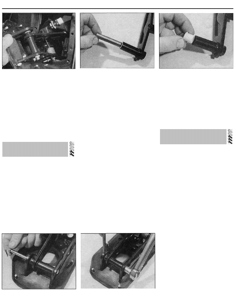
Braking system 9•15
14.5 Removing the pedal bracket
assembly from the bulkhead
the master cylinder bore centrally. Refit the
master cylinder mounting nuts, and tighten
them to the specified torque.
18 Wipe clean the brake pipe unions, then
refit them to the master cylinder ports and
fighten them securely.
19 On left-hand-drive models, refit the
battery tray and battery as described in
Chapter 5.
20 On all models, refill the master cylinder
reservoir with new fluid, and bleed the
complete hydraulic system as described in
Section 2.
14 Brake pedal -
removal and refitting
Removal
1 Remove the steering column as described
in Chapter 10.
2 Remove the vacuum servo unit as
described in Section 15.
3 On models with manual transmission,
referring to Chapter 6 for further information,
slacken the clutch cable adjuster nut to obtain
maximum cable free play. From inside the
vehicle, depress the metal retaining clip, and
free the inner cable from the plastic retainer
fitted to the upper end of the clutch pedal.
4 Disconnect the wiring connector from the
stop-light switch.
5 Slacken and remove the six pedal bracket
retaining nuts, then return to the engine
14.6a With draw the spacer from the brake
p e d a l . . .
compartment and manoeuvre the pedal
bracket assembly out from the vehicle, noting
its rubber seal (see illustration).
6 With the pedal bracket assembly on the
bench, slacken the nut, then withdraw the
pedal pivot pin, and separate the pedal from
the bracket. Slide the spacer out from the
centre of the pedal bore, and remove the pivot
bushes (see illustrations).
7 Carefully clean all components, and renew
any that are worn or damaged; check the
bearing surfaces of the pivot bushes and
spacer with particular care; the bushes can be
renewed separately if worn.
Refitting
8 Press the pivot bushes into the pedal bore,
then apply a smear of multi-purpose grease to
their bearing surfaces, and slide in the spacer.
9 Refit the pedal to the bracket, and install
the pivot bolt. Refit the pivot bolt nut, and
tighten it to the specified torque setting (see
illustrations). Check that the pedal pivots
smoothly before proceeding further.
10 Ensure that the seal is correctly located,
then manoeuvre the pedal bracket assembly
back into position from the engine
compartment. Refit the pedal bracket
retaining nuts, and tighten them to the
specified torque setting.
11 Where necessary, feed the clutch cable
back through the bracket, and engage the
inner cable with the plastic retainer on the
clutch pedal. Check that it is securely retained
14.9a Locate the pedal in the bracket, and
insert the pivot b o l t . . .
14.9b . . . then refit the nut, and tighten it
to the specified torque setting
14.6b . . . and remove the pedal pivot
bushes
by the metal clip. Adjust the clutch cable as
described in Chapter 6.
12 Connect the wiring connector to the stop-
light switch.
13 Refit the servo unit as described in
Section 15.
14 Refit the steering column as described in
Chapter 10. Prior to refitting the lower facia
panel, check and, if necessary, adjust the
stop-light switch as described in Section 21.
Testing
1 To test the operation of the servo unit,
depress the footbrake several times to
exhaust the vacuum, then start the engine
whilst keeping the pedal firmly depressed. As
the engine starts, there should be a noticeable
"give" in the brake pedal as the vacuum builds
up. Allow the engine to run for at least two
minutes, then switch it off. If the brake pedal
is now depressed it should feel normal, but
further applications should result in the pedal
feeling firmer, with the pedal stroke
decreasing with each application.
2 If the servo does not operate as described,
first inspect the servo unit check valve as
described in Section 16. On 16-valve models,
also check the operation of the vacuum pump
as described in Section 25.
3 If the servo unit still fails to operate
satisfactorily, the fault lies within the unit itself.
Repairs to the unit are not possible - if faulty,
the servo unit must be renewed.
Removal
Note: On certain right-hand-drive models, to
gain the clearance required to remove the
servo unit, it may prove necessary to split the
right-hand engine/transmission mounting and
move the engine unit forward slightly; this is
due to the lack of clearance between the
servo unit and the rear of the engine. If this
proves necessary, refer to the relevant Part of
Chapter 2 for further information on
supporting the engine unit and dismantling the
mounting.
15 Vacuum servo unit -
testing, removal and refitting
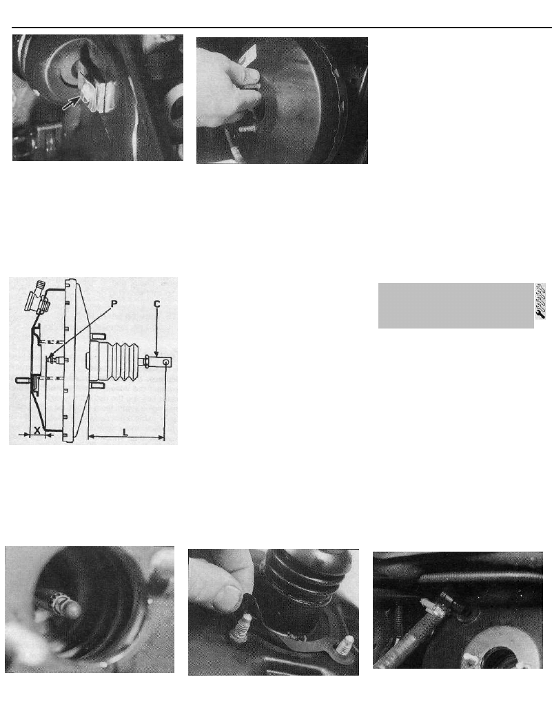
9•16 Braking system
15.7 Servo unit pushrod clevis pin spring
clip (arrowed)
4 Remove the master cylinder as described in
Section 13.
5 Slacken the retaining clip (where fitted) and
disconnect the vacuum hose from the servo
unit check valve.
6 From inside the vehicle, release the panel
fasteners by rotating them through a quarter
15.9a Vacuum servo unit adjustment
dimensions
C Pushrod clevis
P Pushrod nut
L Non-ABS models: 22.3 ± 0.1 mm
ABS models: 24.8 ± 0.1 mm
X Bendix servo unit: 88.0 + 0.5 mm
Teves servo unit: 86.0 + 0.5 mm
15.8 Removing the servo unit
of a turn, and remove the driver's side lower
facia panel. Release the heater duct, and
remove the duct to improve access to the rear
of the servo unit.
7 Prise off the spring clip, then withdraw the
clevis pin securing the servo unit pushrod to
the brake pedal (see illustration).
8 Undo the four retaining nuts securing the
servo unit to the pedal mounting bracket, then
return to the engine compartment and
manoeuvre the servo unit out of position,
noting the gasket which is fitted to the rear of
the unit (see illustration).
Refitting
9 Prior to refitting, check the servo unit
dimensions as follows. With the gasket
removed, check that the pushrod protrusion
from the rear of the unit, dimension "L",
(measured from the rear of the servo unit to
the centre of the pushrod clevis pin hole), and
the distance between the tip of the master
cylinder end of the pushrod and front of the
unit, dimension "X", are as shown in
illustration 15.9a. Where possible, dimension
"L" can be altered by slackening the locknut
and repositioning the pushrod clevis (C).
Dimension "X" can be altered by repositioning
the nut (P) (see illustrations). After
adjustment, ensure the clevis locknut is
securely tightened. Note that on some servo
units adjustment is not possible.
10 Check the servo unit check valve sealing
grommet for signs of damage or deterioration,
and renew if necessary.
11 Fit a new gasket to the rear of the servo
unit, and reposition the unit in the engine
compartment (see illustration).
12 From inside the vehicle, ensure that the
servo unit pushrod is correctly engaged with
the brake pedal, then refit the servo unit
mounting nuts and tighten them to the
specified torque setting.
13 Refit the servo unit pushrod-to-brake
pedal clevis pin, and secure it in position with
the spring clip.
14 Refit the heater duct, ensuring it is
securely connected at either end, then refit
the lower facia panel.
15 Reconnect the vacuum hose to the servo
unit check valve and, where necessary,
securely tighten its retaining clip.
16 Refit the master cylinder as described in
Section 13 of this Chapter.
17 On completion, start the engine and
check for air leaks at the vacuum hose-to-
servo unit connection; check the operation of
the braking system.
Removal
1 Slacken the retaining clip (where fitted), and
disconnect the vacuum hose from the servo
unit check valve.
2 Withdraw the valve from its rubber sealing
grommet, using a pulling and twisting motion.
Remove the grommet from the servo (see
illustration).
Testing
3 Examine the check valve for signs of
damage, and renew if necessary. The valve
may be tested by blowing through it in both
directions. Air should flow through the valve in
one direction only - when blown through from
the servo unit end of the valve.. Renew the
valve if this is not the case.
4 Examine the rubber sealing grommet and
flexible vacuum hose for signs of damage or
deterioration, and renew as necessary.
15.9b Servo unit pushrod adjustment nut
15.11 Prior to refitting, fit a new sealing
gasket to the rear of the servo unit
16.2 Servo unit check valve is a push fit in
its sealing grommet (master cylinder
removed for clarity)
16 Vacuum servo unit check
valve - removal,
testing and refitting
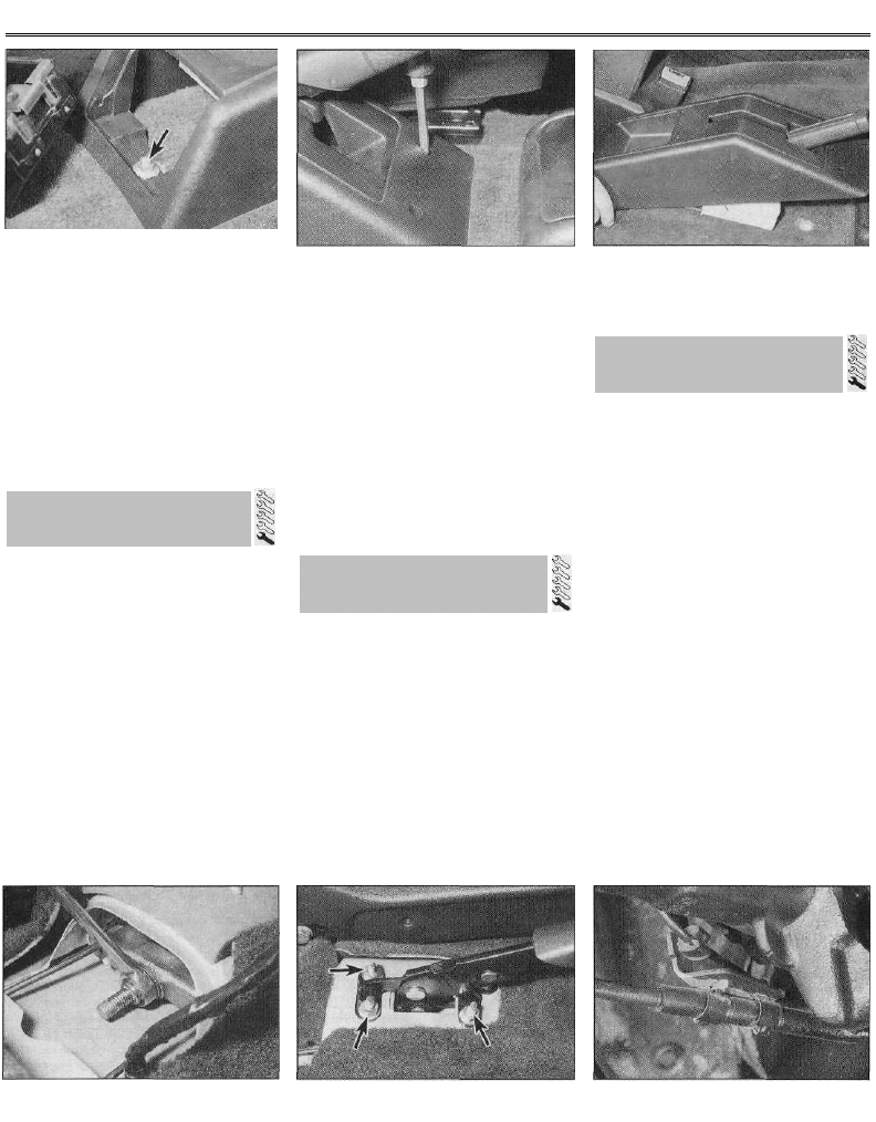
Braking system 9•17
17.2a Remove the ashtray from the rear of
the handbrake cover, then undo the
retaining nut (arrowed)...
Refitting
5 Fit the sealing grommet into position in the
servo unit.
6 Carefully ease the check valve into position,
taking great care not to displace or damage
the grommet. Reconnect the vacuum hose to
the valve and, where necessary, securely
tighten its retaining clip.
7 On completion, start the engine and check
the check valve-to-servo unit connection for
signs of air leaks.
17 Handbrake - adjustment
1 To check the handbrake adjustment, first
apply the footbrake firmly several times to
establish correct shoe-to-drum/pad-to-disc
clearance, then apply and release the
handbrake several times to ensure the self-
adjust mechanism is fully adjusted. Applying
normal moderate pressure, pull the handbrake
lever to the fully-applied position, counting the
number of clicks emitted from the handbrake
ratchet mechanism. If adjustment is correct,
there should be between 4 and 7 clicks before
the handbrake is fully applied. If this is not the
case, adjust as follows.
2 Open up the rear ashtray, then depress the
retaining tang and remove the ashtray from
the handbrake lever cover panel. Slacken and
remove the rear retaining nut and the two
front retaining screws, then manoeuvre the
cover panel off the handbrake lever (see
illustrations).
17.2b . . . and the two front retaining
s c r e w s . . .
3 Chock the front wheels, then jack up the rear
of the vehicle and support it on axle stands.
4 With the handbrake set on the first notch of
the ratchet mechanism, rotate the adjusting nut
until only a slight drag can be felt when the rear
wheels/hubs are turned (see illustration). Once
this is so, fully release the handbrake lever, and
check that the wheels/hubs rotate freely. Check
the adjustment by applying the handbrake fully,
counting the clicks emitted from the handbrake
ratchet and, if necessary, re-adjust.
5 Refit the cover panel over the lever, and
securely tighten its retaining screws and nut.
Clip the rear ashtray back into position, then
lower the vehicle to the ground.
Removal
1 Remove the handbrake lever cover panel as
described in paragraph 2 of Section 17.
2 Slacken the handbrake lever adjusting nut
to obtain maximum free play in the cables,
and disengage the inner cables from the
handbrake lever plate.
3 On models with central locking, undo the
nut and free the central locking control unit
from the handbrake lever mounting studs.
4 Slacken and remove the three handbrake
lever retaining nuts, and remove the lever from
the vehicle (see illustration).
Refitting
5 Refitting is a reversal of the removal. Prior to
17.2c . . . and lift the cover off the
handbrake lever
refitting the handbrake lever cover panel, adjust
the handbrake as described in Section 17.
Removal
1 Remove the handbrake lever cover panel as
described in paragraph 2 of Section 17. The
handbrake cable consists of two sections, a
right- and a left-hand section, which are
linked to the lever by an equalizer plate. Each
section can be removed individually.
2 Slacken the handbrake lever adjusting nut
to obtain maximum free play in the cable(s),
and disengage the inner cables from the
handbrake lever plate.
3 Firmly chock the front wheels, then jack up
the rear of the vehicle and support it on axle
stands.
4 Slacken and remove the retaining nuts,
then release the exhaust system rear heat
shield from the vehicle underbody, to gain
access to the front of the relevant handbrake
cable. Free the front end of the outer cable
from the body, and withdraw the cable from
its support guide.
5 Working back along the length of the cable,
prise off the retaining clip and free it from its
guide, then depress the retaining tangs and
free the cable from its trailing arm bracket
(see illustration).
6 On models with rear drum brakes, remove
the rear brake shoes from the relevant side as
described in Section 6. Using a hammer and
17.4 Adjusting the handbrake
18.4 Handbrake lever is retained by three
nuts (arrowed)
19.5 Handbrake cable trailing arm bracket
18 Handbrake lever -
removal and refitting
19 Handbrake cables -
removal and refitting
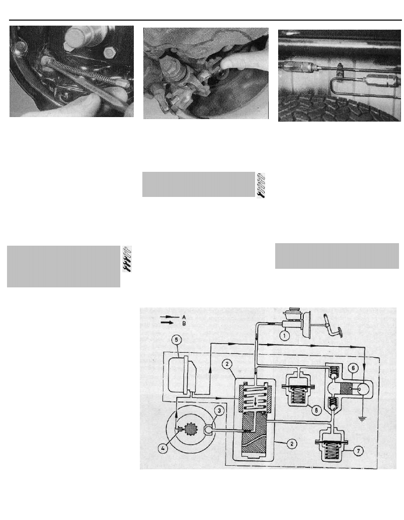
9•18 Braking system
19.6 On drum brake models, drive the
outer cable out from the brake backplate
pin punch, carefully tap the outer cable out
from the brake backplate, and remove it from
underneath the vehicle (see illustration).
7 On models with rear disc brakes, disengage
the inner cable from the caliper handbrake
lever then, using a hammer and pin punch,
tap the outer cable out of its mounting bracket
on the caliper, and remove the cable from
underneath the vehicle (see illustration).
Refitting
8 Refitting is a reversal of the removal
procedure, adjusting the handbrake as
described in Section 17.
20 Rear brake pressure-
regulating valves (models
with rear disc brakes) -
removal and refitting
Note: Before starting work, refer to the
warning at the beginning of Section 2
concerning the dangers of hydraulic fluid.
Removal
1 Firmly chock the front wheels, then jack up
the rear of the vehicle and support it on axle
stands. The pressure-regulating valves are
located just in front of the rear axle assembly;
there are two valves, one for each rear brake
caliper (see illustration).
2 Minimise fluid loss by first removing the
master cylinder reservoir cap, and then
tightening it down onto a piece of polythene,
to obtain an airtight seal.
3 Wipe clean the area around the brake pipe
unions on the relevant valve, and place
absorbent rags beneath the pipe unions to
catch any surplus fluid. Retain the relevant
pressure-regulating valve with a suitable open-
ended spanner, then slacken the union nuts,
disconnect both brake pipes, and remove the
valve from underneath the vehicle. Plug or
tape over the pipe ends and valve orifices, to
minimise the loss of brake fluid, and to prevent
the entry of dirt into the system. Wash off any
spilt fluid immediately with cold water.
Refitting
4 Refitting is a reverse of the removal
procedure, ensuring that the pipe union nuts
19.7 On disc brake models, disconnect the
cable from the brake caliper
are securely tightened. On completion, bleed
the complete braking system as described in
Section 2.
Removal
1 The stop-light switch is located on the
pedal bracket behind the facia.
2 To remove the switch, release the driver's
side lower facia panel fasteners by rotating
them through a quarter of a turn, and remove
the panel. Release the heater duct, and
remove the duct to gain access to the switch.
3 Disconnect the wiring connector, and
unscrew the switch from its mounting bracket.
Refitting and adjustment
4 Screw the switch back into position in the
mounting bracket, until the gap between the
20.1 Rear disc brake pressure-regulating
valves
end of the main body of the switch and the lug
on the brake pedal is approximately 2 to
3 mm.
5 Once the stop-light switch is correctly
positioned, reconnect the wiring connector,
and check the operation of the stop-lights.
The stop-lights should illuminate after the
brake pedal has travelled approximately
5 mm.
6 Refit the heater duct, ensuring it is securely
connected at either end. Refit the lower facia
panel, and secure it in position by rotating its
fasteners through a quarter of a turn.
1 ABS is available as an option on all models
covered in this manual. The system comprises
a modulator block which contains the ABS
computer, the hydraulic solenoid valves and
1 Master cylinder
2 Solenoid valve
3 Brake caliper
22.2 ABS system normal operation
4 Wheel sensor and 6 Return pump
reluctor ring 7 Accumulator
5 ABS computer 8 Accumulator
A Flow of electrical
signal
B Flow of hydraulic
fluid
21 Stop-light switch - removal,
refitting and adjustment
22 Anti-lock braking system (ABS) -
general information
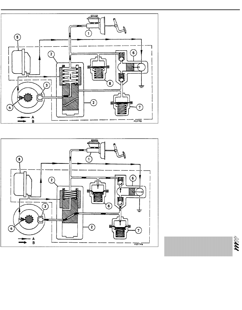
Braking system 9•19
22.3 ABS system "pressure-maintain" phase
Refer to illustration 22.2 for key
22.4 ABS system "pressure-decrease" phase
Refer to illustration 22.2 for key
accumulators, the electrically-driven return
pump, and four roadwheel sensors; one fitted
to each wheel. The purpose of the system is
to prevent the wheel(s) locking during heavy
braking. This is achieved by automatic release
of the brake on the relevant wheel, followed
by re-application of the brake.
2 The solenoids are controlled by the
computer, which itself receives signals from
the four wheel sensors (one fitted on each
hub), which monitor the speed of rotation of
each wheel. By comparing these speed
signals from the four wheels, the computer
can determine the speed at which the vehicle
is travelling. It can then use this speed to
determine when a wheel is decelerating at an
abnormal rate, compared to the speed of the
vehicle, and therefore predicts when a wheel
is about to lock. During normal operation, the
system functions in the same way as a non-
ABS braking system (see illustration).
3 If the computer senses that a wheel is
about to lock, the ABS system enters the
"pressure-maintain" phase (see illustration).
The computer operates the relevant solenoid
valve in the modulator block, which then
isolates the brake caliper on the wheel which
is about to lock from the master cylinder,
effectively sealing-in the hydraulic pressure.
4 If the speed of rotation of the wheel
continues to decrease at an abnormal rate,
the ABS system then enters the "pressure-
decrease" phase (see illustration), where the
electrically-driven return pump operates and
pumps the hydraulic fluid back into the master
cylinder, releasing pressure on the brake
caliper so that the brake is released. Once the
speed of rotation of the wheel returns to an
acceptable rate, the pump stops; the solenoid
valve opens, allowing the hydraulic master
cylinder pressure to return to the caliper,
which then re-applies the brake. This cycle
can be carried out at up to 10 times a second.
5 The action of the solenoid valves and return
pump creates pulses in the hydraulic circuit.
When the ABS system is functioning, these
pulses can be felt through the brake pedal.
6 The solenoid valves connected to the front
calipers operate independently, but the valve
connected to the rear calipers operates both
calipers simultaneously. Since the braking
circuit is split diagonally, a separate
mechanical plunger valve in the modulator
block divides the rear solenoid valve hydraulic
outlet into two separate circuits; one for each
rear brake.
7 The operation of the ABS system is entirely
dependent on electrical signals. To prevent
the system responding to any inaccurate
signals, a built-in safety circuit monitors all
signals received by the computer. If an
inaccurate signal or low battery voltage is
detected, the ABS system is automatically
shut down, and the warning light on the
instrument panel is illuminated, to inform the
driver that the ABS system is not operational.
Normal braking should still be available,
however.
8 If a fault does develop in the ABS system,
the vehicle must be taken to a Citroen dealer
for fault diagnosis and repair.
23 Anti-lock braking system
(ABS) components -
removal and refitting
Modulator assembly
Note: Before starting work, refer to the note at
the beginning of Section 2 concerning the
dangers of hydraulic fluid.
Removal
1 Disconnect the battery negative terminal.
2 Undo the retaining screw, and remove the
relay cover from the modulator assembly.
3 Disconnect the large 15-pin connector, the
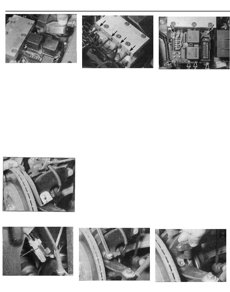
9•20 Braking system
23.3 Disconnecting the large wiring
connector from ABS modulator computer
(square connector arrowed)
square 4-pin connector, and the return pump
earth lead, from the modulator (see
illustration).
4 Unscrew the master cylinder reservoir filler
cap, then place a piece of polythene over the
filler neck, and securely refit the cap. This will
minimise brake fluid loss during subsequent
operations. As a precaution, place absorbent
rags beneath the modulator brake pipe
unions.
5 Wipe clean the area around the modulator
brake pipe unions, then make a note of how
the pipes are arranged, to use as a reference
on refitting; the four modulator outlet unions
are marked, to aid refitting. Unscrew the union
nuts, and carefully withdraw the pipes (see
illustration). Plug or tape over the pipe ends
and valve orifices, to minimise the loss of
23.12 Remove the shield from the top of
the front wheel sensor . . .
23.5 ABS modulator block brake pipe
unions (arrowed)
brake fluid, and to prevent the entry of dirt into
the system. Wash off any spilt fluid
immediately with cold water.
6 Slacken the mounting nuts, and remove the
modulator assembly from the engine
compartment. Note that the nuts do not need
to be removed, since the mounting bracket
bolt holes are slotted. Note: Do not attempt to
dismantle the modulator block hydraulic
assembly. Overhaul of the unit is a complex
job, which if necessary should be entrusted to
a Citroen dealer.
Refitting
7 Refitting is the reverse of the removal
procedure, noting the following points:
(a) Tighten the modulator block mounting
nuts securely.
(b) Refit the brake pipes to their respective
unions, and securely tighten the union
nuts.
(c) Ensure the wiring is correctly routed, and
the connectors firmly pressed into
position.
(d) On completion, and prior to refitting the
battery, bleed the complete braking
system as described in Section 2. Ensure
the system is bled in the correct order, to
prevent air entering the modulator return
pump.
ABS computer
Removal
8 Disconnect the battery negative terminal,
23.9 ABS modulator computer retaining
screws (arrowed)
then slacken the retaining screw, and remove
the relay cover from the modulator assembly.
9 Disconnect the three wiring connectors
from the computer unit, then slacken and
remove the six Torx retaining screws, and lift
the computer away from the modulator
assembly (see illustration).
Refitting
10 Refitting is a reversal of the removal
procedure, ensuring that the computer
retaining screws are securely tightened and
the wiring connectors are firmly reconnected.
Front wheel sensor
Removal
11 Chock the rear wheels, then firmly apply
the handbrake, jack up the front of the vehicle
and support on axle stands. Remove the
appropriate front roadwheel.
12 Slacken and remove the bolt securing the
wiring retaining bracket to the top of the
swivel hub assembly, then undo the retaining
nut and remove the shield from the top of the
sensor (see illustration).
13 Trace the wiring back from the sensor to
the connector, freeing it from all the relevant
retaining clips, and disconnect it from the
main loom (see illustration).
14 Slacken and remove the bolt securing the
sensor to the swivel hub, and remove the
sensor and lead assembly from the vehicle
(see illustrations).
23.13 . . . then trace the sensor wiring
back to its wiring connector, and
disconnect it
23.14a Slacken and remove the retaining
b o l t . . .
23.14b . . . and remove the sensor from
the swivel hub
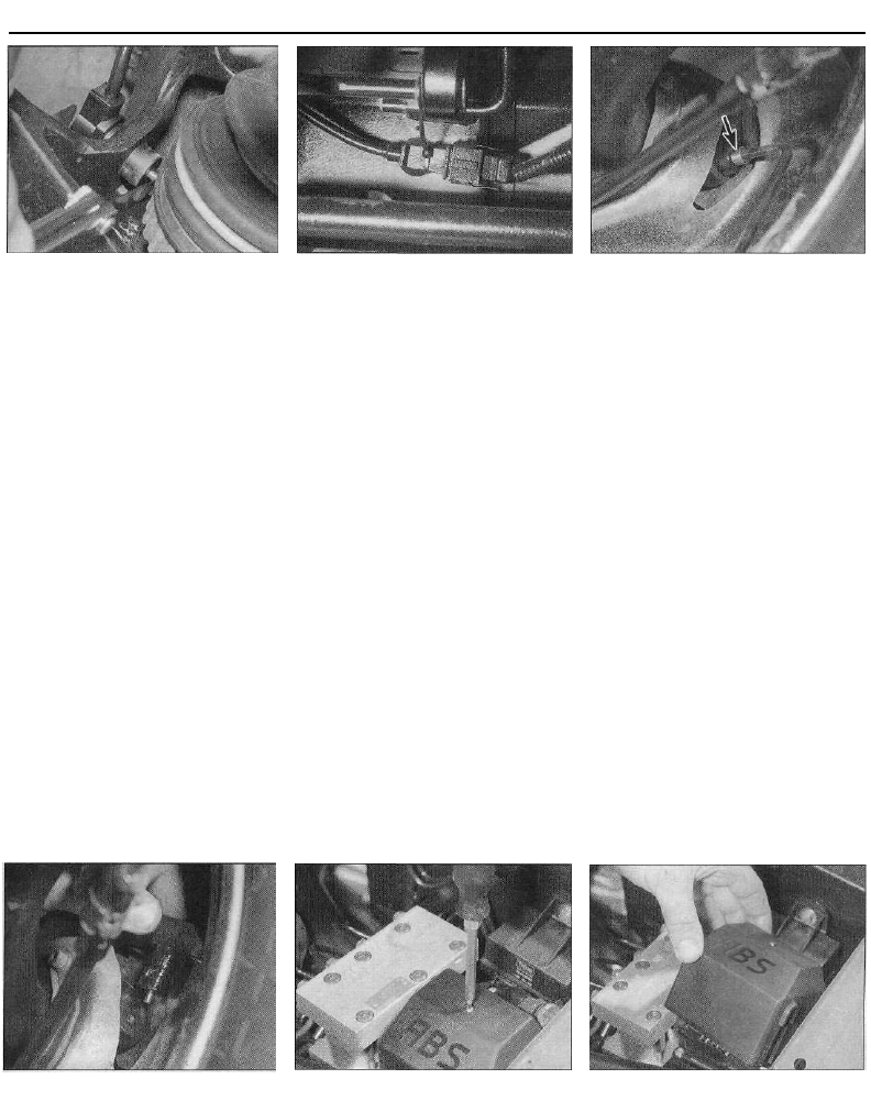
Braking system 9•21
23.17 Checking the front wheel sensor air 23.21 Rear wheel sensor wiring
gap connectors are located just in front of the
rear axle
Refitting
15 Prior to refitting, apply a thin coat of multi-
purpose grease to the sensor tip.
16 Ensure that the sensor and swivel hub
sealing faces are clean, then fit the sensor to
the hub. Apply a few drops of locking fluid to
the sensor bolt, then refit the bolt and tighten
it to the specified torque.
17 Rotate the hub until one of the reluctor
ring teeth is correctly aligned with the sensor
tip. Using feeler gauges, measure the air gap
between the tooth and sensor tip (see
illustration). Rotate the hub, and repeat the
procedure on several other teeth. If the air gap
is not within the specified range given in the
Specifications at the start of this Chapter,
then the advice of a Citroen dealer must be
sought.
18 Ensure the sensor wiring is correctly
routed and retained by all the necessary clips,
and reconnect it to its wiring connector.
19 Refit the roadwheel, then lower the
vehicle to the ground and tighten the
roadwheel bolts to the specified torque.
Rear wheel sensor
Removal
20 Chock the front wheels, then jack up the
rear of the vehicle and support it on axle
stands. Remove the appropriate roadwheel.
21 Trace the wiring back from the sensor to
its wiring connector, which is situated just in
front of the rear axle (see illustration). Free
the connector from its retaining clip, and
disconnect the wiring from the main wiring
loom.
22 Work back along the sensor wiring, and
free it from any relevant retaining clips.
23 Slacken and remove the bolt securing the
sensor unit to the trailing arm, and remove the
sensor and lead assembly from the vehicle
(see illustrations).
Refitting
24 Prior to refitting, apply a thin coat of multi-
purpose grease to the sensor tip.
25 Ensure that the sensor and trailing arm
sealing faces are clean, then fit the sensor and
tighten its retaining bolt to the specified
torque.
26 Rotate the disc until one of the reluctor
ring teeth is correctly aligned with sensor tip.
Using feeler gauges, measure the air gap
between the tooth and sensor tip. Note that
this may prove difficult with the disc shield in
position. Rotate the disc, and repeat the
procedure on several other teeth. If the air gap
is not within the specified range given in the
Specifications at the start of this Chapter,
then the advice of a Citroen dealer must be
sought.
27 Ensure the sensor wiring is correctly
routed and retained by all the necessary
retaining clips, and reconnect it to the wiring
connector.
23.23a Undo the retaining bolt
(arrowed)...
28 Refit the roadwheel, then lower the
vehicle to the ground and tighten the
roadwheel bolts to the specified torque.
Front reluctor rings
29 The front reluctor rings are an integral part
of the driveshaft outer constant velocity (CV)
joints, and cannot be renewed separately.
Examine the rings for damage such as
chipped or missing teeth. If renewal is
necessary, the complete outer constant
velocity joint must be renewed as described in
Chapter 8.
Rear reluctor rings
30 The rear reluctor rings are an integral part
of the rear hub assembly, and cannot be
renewed separately. Examine the rings for
signs of damage such as chipped or missing
teeth, and renew as necessary. If renewal is
necessary, the rear hub assembly must be
renewed as described in Chapter 10.
Relays
31 Both the solenoid relay and return pump
relay are located in the modulator block
assembly. To gain access to them, undo the
relay cover retaining screw and lift off the
cover. Either relay can then be simply pulled
out of position (see illustrations). Refer to
Chapter 12 for further information on relays.
23.23b . . . and remove the rear wheel
sensor from the trailing arm
23.31a Undo the retaining screw . . .
23.31 b . . . and lift the relay cover off the
modulator block . . .
9•22 Braking system
24 Vacuum pump (16-valve
models) - removal and refitting
Removal
1 Release the retaining clip and disconnect
the vacuum hose from the top of pump.
2 Slacken and remove the two bolts securing
the pump to the left-hand end of the cylinder
head, then remove the pump. Remove the
pump O-ring (where fitted) and discard it - a
new one must be used on refitting.
Refitting
3 Where an O-ring was fitted, fit a new O-ring
to the pump. Where no O-ring was fitted,
apply a smear of suitable sealant to the pump
mating surface.
4 Align the pump drive dog with the slot in the
23.31c . . . to gain access to the ABS
relays
camshaft end, then refit the pump to the
cylinder head. Refit the pump mounting bolts,
and tighten them securely.
5 Reconnect the vacuum hose to the pump,
and securely tighten its retaining clip.
25 Vacuum pump (16-valve
models) - testing and overhaul
1 The operation of the braking system
vacuum pump can be checked using a
vacuum gauge.
2 Disconnect the vacuum pipe from the
pump, and connect the gauge to the pump
union using a suitable length of hose.
3 Start the engine and allow it to idle, then
measure the vacuum created by the pump. As
a guide, after one minute, a minimum of
approximately 500 mm Hg should be
recorded. If the vacuum registered is
significantly less than this, it is likely that the
pump is faulty. However, seek the advice of a
Citroen dealer before condemning the pump.
4 Overhaul of the vacuum pump is not
possible, since no components are available
separately for it. If faulty, the complete pump
assembly must be renewed.
Wyszukiwarka
Podobne podstrony:
download Zarządzanie Produkcja Archiwum w 09 pomiar pracy [ www potrzebujegotowki pl ]
09 AIDSid 7746 ppt
09 Architektura systemow rozproszonychid 8084 ppt
TOiZ 09
Wyklad 2 TM 07 03 09
09 Podstawy chirurgii onkologicznejid 7979 ppt
Wyklad 4 HP 2008 09
09 TERMOIZOLACJA SPOSOBY DOCIEPLEŃ
09 Nadciśnienie tętnicze
wyk1 09 materiał
Niewydolność krążenia 09
09 Tydzień zwykły, 09 środa
09 Choroba niedokrwienna sercaid 7754 ppt
TD 09
moj 2008 09
IU 09
więcej podobnych podstron