30
Panzerbeobach
By Tom Cockle
31
tungswagen IV
T
he first time I became aware
of this unique vehicle was
when I saw a color profile of it
in the book, ‘Pzkpfw.IV Model
Fibel’, by the Japanese
publisher Model Art in 1999. No way, I
thought. A Panzer IV with a StuG.III
commanders cupola! Where did they
dream that up? Then someone pointed out
there was a photo of one in ‘Battle of the
Bulge, Then and Now’ with a cute little
teddy bear perched on top of the gun. I
don’t know how many times I had looked at
that picture before without noticing the
cupola, but there it was in black and white.
Three more photographs of one lost on the
Eastern Front appeared in two Russian
publications, ‘German Camouflage and
Insignia 1941-1945’ in the Armada-Vertical
Series by Exprint Publishing Center and
‘Frontline Illustration Wehrmacht Panzer
Units in 1945’ Part I. Information on it was
scarce, then, just before Christmas, Osprey
released their new book
‘Panzerkampfwagen IV Ausf.G, H and J
1942-45’, by Hilary Doyle and Tom Jentz,
and most of the pieces of the puzzle
seemed to fall in place. The subject of the
color profile in the ‘Pzkpfw.IV Model Fibel’
that had first caught my eye, had a large
tactical number ‘B1’ painted on the rear
quarters of the turret skirts. Where had this
come from? Fortunately an inquiry posted
on the Missing-Links Panzer Talk discussion
group resulted in the answer. A scan of a
photograph taken from a Ground Power
magazine and sent to me by James
Blackwell, along with a translation of the
Japanese caption by Jeensang Jang,
32
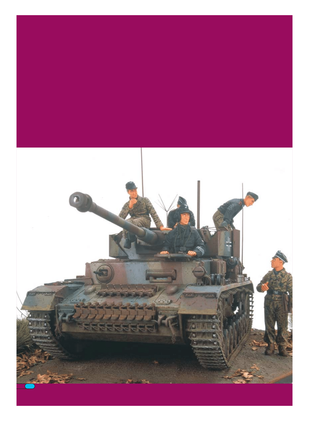
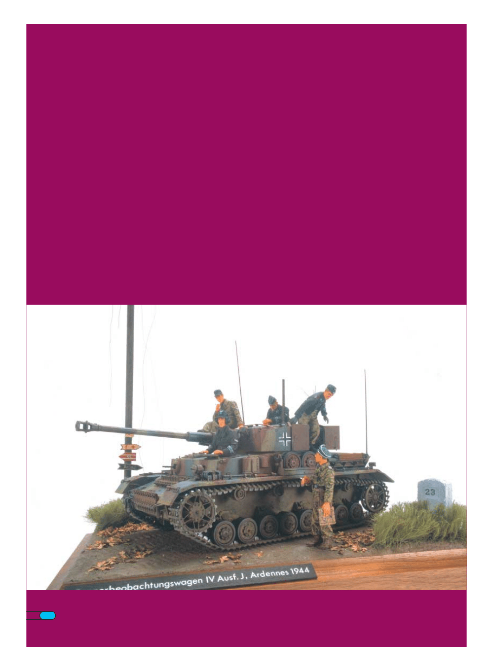
placed it at Weisswampach in Luxembourg in early 1945. The
best information, according to Stefan De Meyer, suggests that
it probably belonged to 12.SS-Panzer-Division.
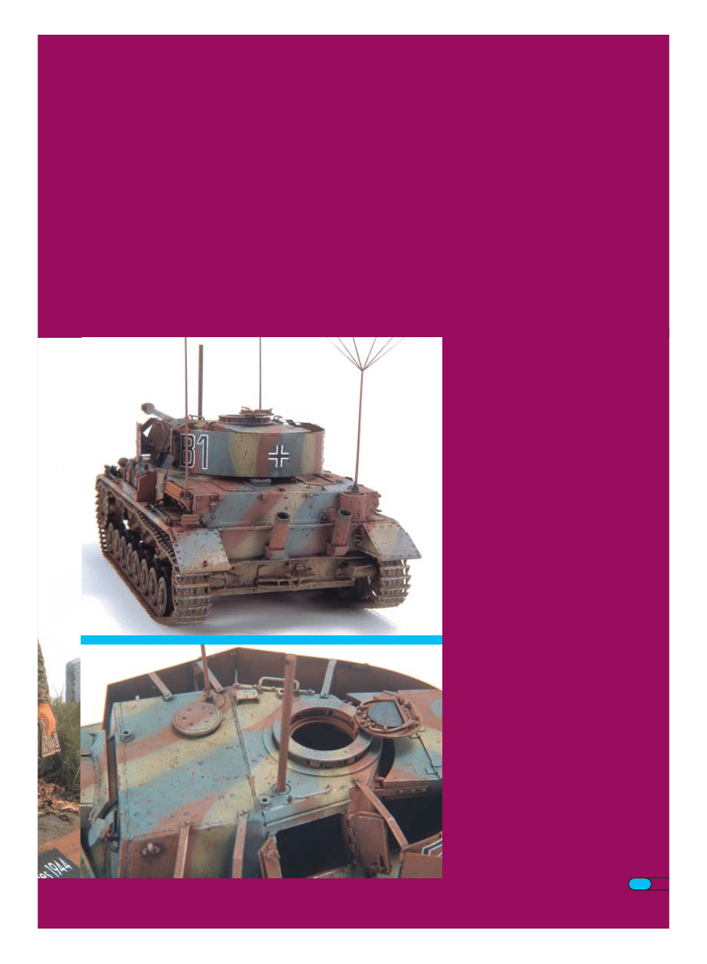
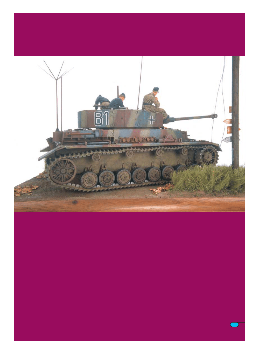
The one clearly identifiable feature of ‘B1’ is that it was fitted
with the vertical Flammentöter flame suppressing exhausts
that were first installed beginning in August 1944. I decided
that I would build mine with features that would place it in
production in late September 1944. These would include
having no Zimmerit applied but still retaining the early bolted
on tow brackets. Records show that 12.SS-Panzer-Division
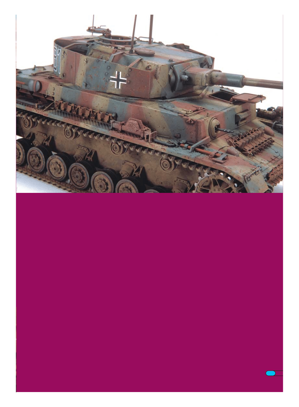
received five new Pz.Beob.Wg.IV on 11 November 1944. It is
shown here as it might have looked on the opening day of the
Ardennes Offensive, 16 December 1944.
Choose Your Weapons
My choice for a kit was the Tamiya Panzerkampfwagen IV
Ausf.J No. 35181. As usual, I started on the lower hull and
running gear. Two bolt heads were added to the flat upper
surface of each roadwheel damper and grease nipples added
to the center of the idler wheel and each return roller. At some
point during Ausf.J production, two bolts from the top row on
the roadwheel mounts were deleted. In earlier cases, this is
evident by two empty holes and on later vehicles, the holes
were not drilled at all. I opted for a combination following the
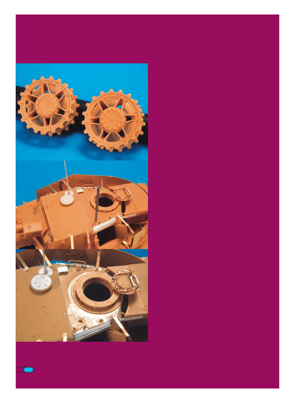
photos of the Pz.Bef.Wg.IV at the Brussels museum. The drive
sprocket got the works though with new, more realistic looking
bolt heads around the outside of the inner and outer halves
that were taken from spare drive sprockets from the new
Tamiya Tiger II. Nuts and bolts shaved from old Tamiya Tiger II
roadwheels were added on the inner face of the inside half.
The tracks are from an older set of Model Kasten K-2 non-
workable individual links that need to be glued together but
look every bit as good as the newer workable sets when
finished.
I had noticed that the bottom intakes on the sides of the
engine deck on the Pz.Bef.Wg.IV at Brussels did not curve up
from the mudguard like the kit parts and so these were
removed and replaced with sheet plastic. After this was
complete, the upper and lower hull parts were glued together
along with some .030 plastic card to close off the opening in
the sponsons above the tracks. This was set aside to dry
completely and I turned my attention to the turret assembly.
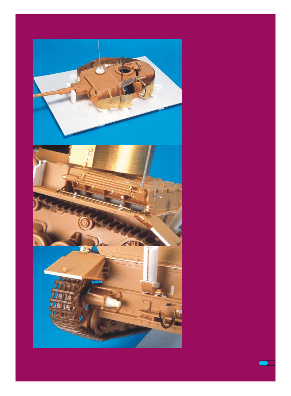
The Turret Takes Shape
The first task was to remove all traces of the cupola ring
molded onto the turret roof and to enlarge the hole to receive
a cupola taken from a Tamiya StuG.III Ausf.G kit. I elected to
just use the one from the kit that I will replace at some future
33
date by ordering a new sprue from
Japanese retailer ‘Rainbow Ten’. The
cupola hatch received some detail
attention in the form of bent brass strip
handles, a copper wire closing arm and
Grandt Line nuts and bolts. The pattern of
screw heads on the roof was traced on to
a piece of tracing paper using drawings
and transferred to the kit part using a
compass point. They were then drilled out
and photoetch brass screw heads from
Royal Models Screws and Bolts Set
No.034 were glued in place. A new larger
diameter, reinforced ventilator cover was
made from an old Tamiya Jagdtiger
ventilator and Royal Model photoetch
brass screws were added as well. This
larger ventilator cover was introduced in
July 1944, yet neither the Tamiya nor the
Dragon kits include it. Just to the right of
the ventilator, an antenna base was added
where the ‘Nahverteidigungswaffe’ would
have normally been installed. The antenna
and base came from Dragon’s German
Tank Antenna set. On the left side of the
roof, a periscope was added. At its base, a
circle was scribed in and sectioned into
three segments using photographs as
reference.
New grab handles were made from bent
brass wire and glued into holes drilled
about a millimetre farther back. When you
study the relationship of the handle to the
Pilze and the rain gutter over the turret
doors, you can see it needs to be moved.
New rain gutters were made from thin
metal printers plate bent over a steel ruler.
All the welded joints were vee’d out and
new weld beads made from Zimm-It-Rite
epoxy putty were added. Texturing was
done using a round toothpick that had a
small groove carved in the end. This
applies to all the weld beads on the rest of
the model as well.
The turret stowage bin was glued together
and allowed to dry thoroughly before filing
the joint smooth and scribing in a new line
to separate the lid from the bin. The two
mounting points were removed and the
groove in the bottom was filled with a
piece of styrene carefully cut to fit. The
bottom and side brackets are made from
styrene strip. I added Royal Model hasps
to the rear of the bin but the turret skirt
armour obscures their fine detail.
Panzerbeobachtungswagen IV
34
Since Tamiya thoughtfully provided a
separate gunners vision flap in the front of
the turret, I added two arms and glued it in
place in an open position. A lightly tinted
green clear plastic strip was glued in from
the back after painting to represent the
armoured glass. A small tin plate rain
gutter was added above the gunsight
opening in the mantlet. Pz.Bef.Wg. and
Pz.Beob.Wg.IV were not equipped with a
coaxial machine gun so I drilled out the
opening and opened up the cooling slots in
the top and bottom of the armored sleeve
on the mantlet. After gluing the halves of
the gun barrel together, I carefully sanded
it by twirling it inside a strip of sandpaper
while slowly moving it up and down the
length of the barrel. Done properly, this will
give you a seamless barrel. Three small
rivet heads and three small screw heads
were added to the armored sleeve in front
of the recuperator housing and a small
plastic ring on the top left side.
The locking handles on the turret side
access doors were separated from the
hatch face and the bottom two were
further drilled out and slotted. New hatch
hold open brackets were made from sheet
styrene and rod.
Now comes the fun part. I bought a set of
Aber photoetch brass turret skirts (35A06)
thinking this would save me all kinds of
time over scratchbuilding. I soldered
together the brackets first, bending them
to shape and laying them flat on a ceramic
tile. They were held in place with small
blobs of Blu-Tac. To properly align the
skirts to the turret, I made a jig from sheet
styrene with a hole the same size as the
one in Tamiya’s upper hull and glued short
pieces of .156 styrene strip around to
support the bottom edge of the skirt. Two
upright pieces were glued on either side of
the gun barrel to keep the turret from
moving. Aber gives you small pieces of
brass with holes in them to glue to the
turret but I decided to use styrene strip
instead. I superglued these to the brackets
which then could be glued to the turret
using liquid poly allowing for some
adjustment in the final position. Here I ran
into my first major problem. Aber’s skirts
are about a millimeter higher than both the
Tamiya skirts and Hilary Doyle’s drawings
and therefore, the top of the two rear
brackets was that much higher than the
top of the turret. To correct this, I simply
melted off the gusset, adjusted the angle
and soldered in a new gusset cut from the
photoetch runner. The top of the bracket
looks a little flat, but is not noticeable Aber
gives you some photoetch bolt heads but
for some strange reason, they don’t give
enough. I was fortunate to have some left
over from their Panther set I was able to
Panzerbeobachtungswagen IV
35
use. The nuts and bolts used to detail the
inside came from Grandt Line.
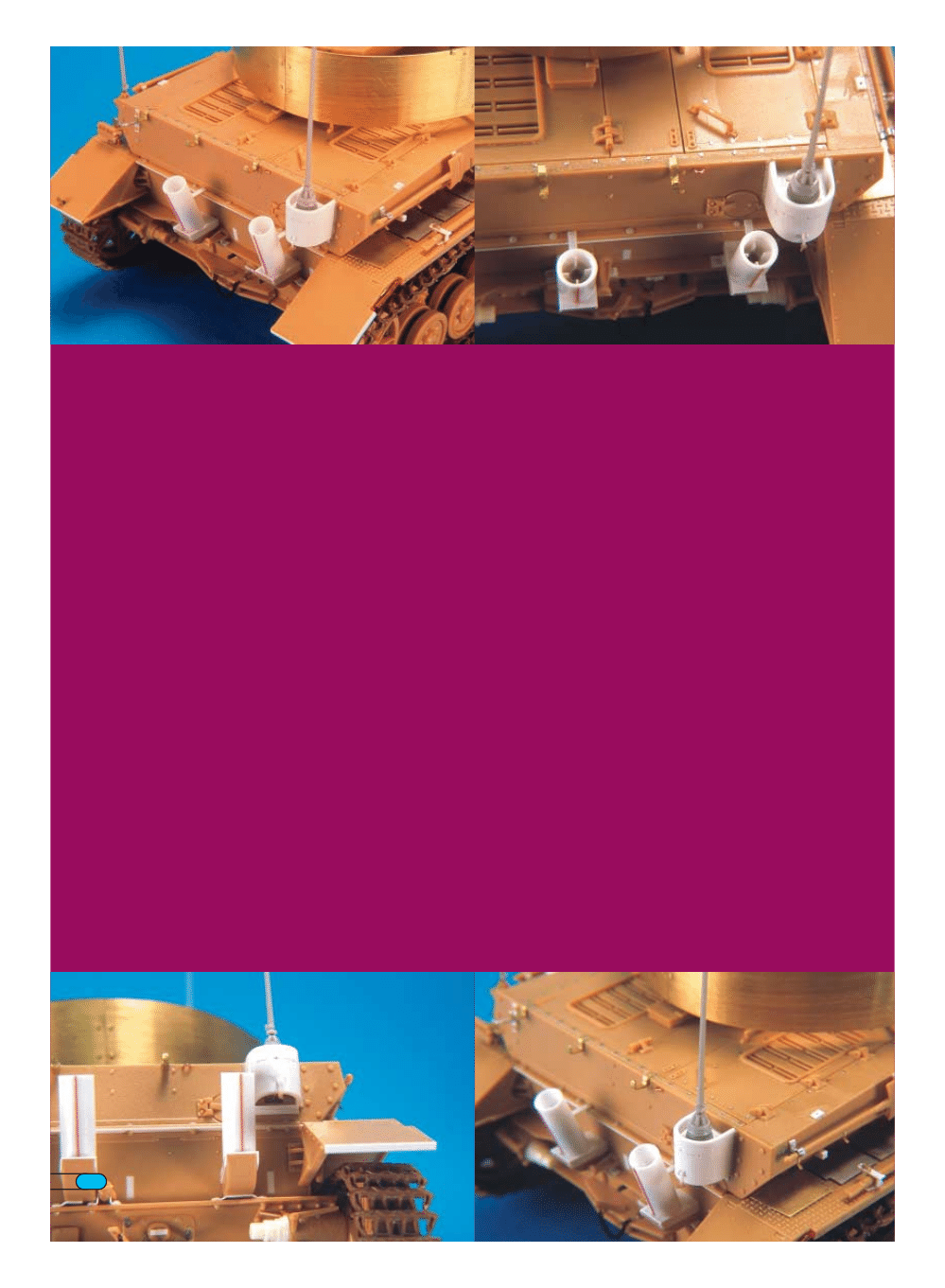
Back to the Hull
Moving back to the hull, the first thing I did
was tackle the armored housing welded to
the back of the hull that was unique to the
Pz.Bef.Wg.IV and Pz.Beob.Wg.IV. I took a
piece of .030 styrene strip and immersed it
for a few seconds in boiling water. It was
then quickly formed around a small X-acto
knife handle and then run under cold water
so it would retain its shape. The ends were
cut to the angle of the rear plate and it was
glued in place. The mount for the star
antenna is recessed down from the top
and a small piece of styrene was cut to
shape and glued in. Three small drain
holes were drilled into the housing just
above this. The antenna mount itself came
from the Dragon German Antenna set
which, I believe, is no longer available. I’m
glad I bought a few of them while I could
as the antennas are perfect, especially the
star antenna which is provided as a
stainless steel photoetch piece. There was
a special porcelain insulator on the base of
this antenna, also provided by Dragon. The
bottom of the housing is open and the
heavy cable from the antenna passes
through a rectangular hole in the rear
plate. After reproducing all this detail, I
came to realize that there was a sheet
metal cover plate underneath that was
supported by an angle welded to the rear
plate and held in place by a pivoting wing
nut on the outside of the housing. It would
have been far simpler to just close off the
bottom but, for my model, this plate is just
missing in action.
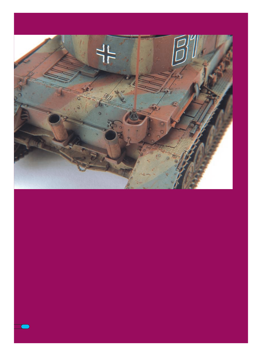
New Flammentöter exhaust pipes replaced
the kit exhaust and were made from
styrene tube. I made the inner pipe from
another piece of styrene tube and attached
it to the outer tube with four small styrene
strip vanes.
The double angle flange connecting the
upper and lower hull was detailed with an
additional styrene strip and numerous bolt
heads and nuts. At the bottom of the rear
plate, the idler mounts were actually
fastened on with nuts while the kit is
molded with bolt heads. This was a simple
36
thing to correct by simply gluing on small
stubs shaved from the bottom of a Dragon
Pz.Kpfw.IV hull. Coincidentally, about the
time I was doing this, there was a posting
on Missing-Links that pointed out that the
large hex nuts on part D34 used to tension
the idlers should really be octagonal. So I
made a pair of octagonal nuts from .125 x
.125 styrene strip and, using part D34 from
another kit, made a master which I then
molded and cast new ones in resin.
The rear mudguards had a styrene strip
added to the back and outside edges.
Small rivet heads were added to the inside
faces, parts B4 and B5, lining up with the
ones on the large flat face. To make the
springs, I wrapped a thin wire around a
small drill bit chucked backwards in to my
pin vise. Remember to count the wraps so
both sides are the same.
When it comes to adding the tools and
other details, I usually start at one point
and work my way around the vehicle
instead of jumping around all over. The first
thing to do is fill all the locating holes. After
all this time, you would think the
manufacturers would realize how much we
detest these molded in imperfections.
I started with the Notek light on the left
rear mudguard. It is the Tamiya kit part
with the base removed and a new one
added from bent brass strip along with a
very thin wire lead running down through a
hole in the mudguard.
The cover plates lying flat on the
mudguard for the engine air intake louvers
are stainless steel photoetch ones from
Tamiya. The one at the back below the
standard antenna mount needs to have a
small recess filed into it to clear the
antenna base which actually projects
down. I got the two sides mixed up and as
a result, had to make a new one for the
right side from brass sheet. The little
spring clips that hold them up were made
from narrow brass runners from another
photoetch brass sheet. I made a little jig
with a piece of triangular plastic glued to it
to form them over so they would all be a
uniform size.
The gun cleaning rods are from the kit and
were detailed with brass strip mounts on
the back to space them away from the hull
and Royal Models photoetch brass hasps
were added. The pry bar was made from a
piece of brass rod. I flattened and bent
one end with a pair of pliers and then filed
it to shape. The brackets are my own
design made from brass runners and
another jig made using a piece of half-
round styrene. Each one is two parts that
are then glued to a piece of .010 styrene
strip so they can be attached to the kit
with styrene cement.
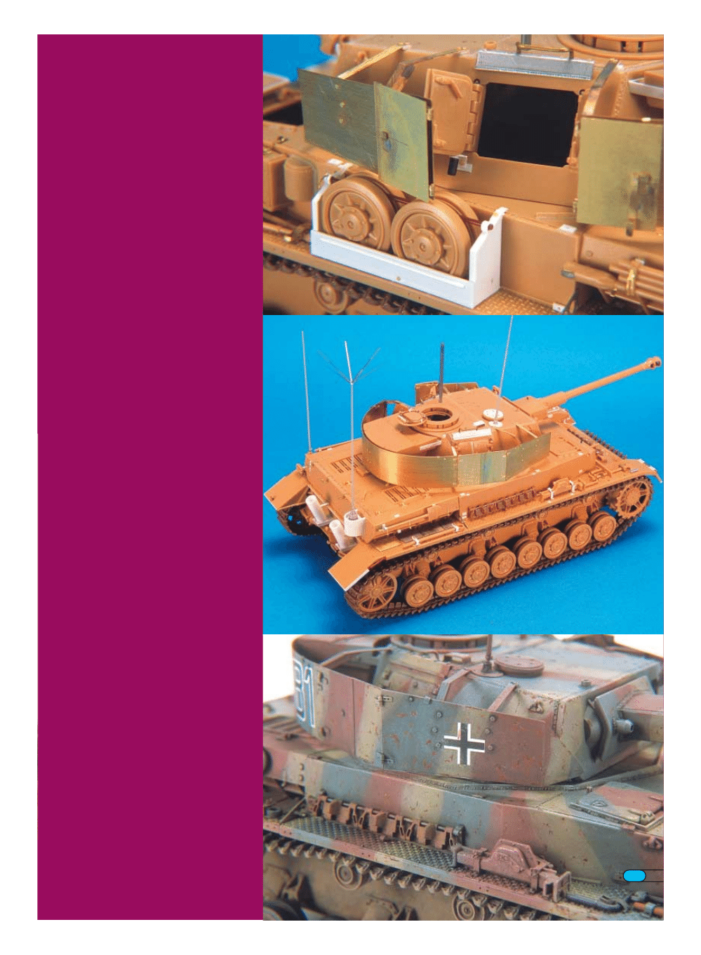
The spare roadwheel box was made from
.010 sheet and strip styrene using the kit
parts as a guide as they are actually thin
sheet metal. The raised rib on the side
panel is a piece of half-round styrene.
37
I detailed the jack block with a wire spring
and a photoetch brass chain. The clamp for
the wire cutters is from an Aber workable
set as are all the others used on this
model. The short pry bar and brackets
were made the same way as the one on
the back except the bar is styrene.
In the Osprey New Vanguard book by Doyle
and Jentz, they state that S-hooks replaced
the C-hooks on Pz.Kpfw.IV starting in June
1944 but I could not find even one
photograph to substantiate this. I did,
however, find several photographs of late
Pz.Kpfw.IV fitted with mesh skirts
(September 1944) and the rotating cupola
hatch (October 1944) that still had the C-
hook bracket. Not having a photoetch
brass detail set with one handy, I made one
from styrene sheet. The C-hooks are from
the kit and were thinned down a bit to fit in
the new bracket.
The fire extinguisher is one from the new
Royal Models German Fire Extinguisher Set
No.247, I modified the headlight mount by
cutting out a slot in the base on the
outboard side and adding a copper wire
electrical lead down to the glacis. The
headlight itself is one I had left over from
an old Gunze Sangyo High-Tech Panther
which I used simply because I had it and it
is nicely detailed.
You will notice that the two large wrenches
stowed behind the fire extinguisher are not
there as they were deleted at some point in
Ausf.J production. At least they are not on
Hilary Doyle’s drawings of the Pz.Bef.Wg.IV
and Pz.Beob.Wg.IV in the ‘Begleitwagen
Panzerkampfwagen IV’ book. This
presented a bit of a challenge as the
brackets for them are molded on the
mudguard. I carefully ground them off with
a flat Dremel bit and repaired the
treadplate pattern by removing the small
pieces from another kits mudguard, under
the area where the engine intake flaps lie,
and gluing them carefully in place. A couple
of days after I finished the model, I picked
up a new book published in Russia on Lake
Balaton in which there is a photo of a
Bergepanzer IV with the two wrenches
mounted in brackets on the front and rear
of the spare roadwheel bin. These two
brackets were also on the Pz.Bef.Wg.IV in
Brussels but I didn’t know what they were
for at the time, so I had left them off.
38
Armed with this new information, I added
them along with the two wrenches.
Moving to the front, the spare track links and
brackets come from the Model Kasten SK-19
Late Model Spare Track set. The pins in the
tow brackets are from the kit detailed with
fine chain. The square transmission access
plate on the glacis had the hex bolt heads
removed and replaced with square heads
made from styrene strip. In addition, the
simulated screw heads surrounding it were
gently cleaned out with a flat Dremel bit
twirled in my fingers to remove the raised
‘slot’ and Royal Models screws were glued in.
The hinged part of the front mudguards were
detailed with a piece of styrene rod on the
bottom edge and new hinges and pins made
from a piece of telephone wire that had most
of the insulation removed. The remaining
insulation forms part of the hinge. The inside
face of the mudguards had some small
details added from styrene strip, rivets and
bolt heads and wire springs made the same
way as the ones on the rear.
On the engine deck, I added several rows of
raised blank bolt heads made by punching
out a piece of lead foil on an eraser with a
.020 drill bit chucked backwards into my pin
vise. It’s odd that Tamiya did not reproduce
these as they did on their earlier Panzer IV
kits because they are quite noticeable.
Incidentally, the rear hinge on the right side
hatch should be moved forward a bit, which I
did not do as I discovered it too late. Check
out the drawings in ‘Panzer Tracts No.4’ or
the ‘Begleitwagen’ book.
The drivers and radio operators hatches in
the kit are the earlier welded edge type
which were replaced with thicker ones with
rounded edges beginning in July 1944,
although existing stocks were installed until
they were used up. I rounded off the edge
with a file and detailed the inside of the
driver’s hatch with a new locking handle and
bar. The raised edge was made by adding
strip styrene around the hatch and trimming
off the excess after the glue was dry. Just
behind the hatches, there was a weld joint
that is missing on the kit. I scribed in a deep
groove and filled it with Zimm-It-Rite epoxy
putty weld.
This completed the construction phase of the
model.
Time to Paint
In September 1944, German tanks began to
leave the factory with a coat of RAL 8012 Rot
primer with a camouflage pattern of RAL
7028 Dunkelgelb and RAL 6003 Olivgrün
sparingly applied in stripes and patches with
hard edges. The lower hull sides and wheels
were not camouflage painted. I like to use
Testors Model Master Acryl paints, but there
is not a suitable color to represent the primer
and I used an old Humbrol color HG15
(RLM61). This matches very closely a paint
sample I have adhered to the back of a piece
of Zimmerit coating from a Panther. After
this, I sprayed on the camouflage using
Model Master Acryl 2095 Panzer Dunkelgelb
1943 and 2097 Panzer Olivgrün 1943, mixed
50/50 with their acrylic thinner. When this had
dried, the hard edges were touched up with
a brush using the leftover thinned paints,
which worked surprisingly well. As the vehicle
would have been camouflaged in the factory
with the Schürzen brackets still mounted, I
touched up all the mounting lugs with primer
color.
The rubber tyres were painted with Vallejo
acrylic that brushed on extremely well right
from the bottle.
I tried a new wash technique demonstrated
by Chris Mrosko in his book ‘Panzer’s
Tactics’. He uses a thinned black oil wash
applied directly over the base paint which
eliminates the need for the clear acrylic
sealer coat and the messy, time consuming
39
effort required to wipe off the thick oil wash
that I previously used.
The black oil wash is thinned with paint
thinner, not turpentine, to produce a flat
finish. A small amount of paint is placed on
a palette to which small amounts of thinner
are added to obtain the right consistency.
This is brushed liberally over the whole
model. Next, after drying for a day, a ‘pin
wash’, made from burnt sienna and
Vandyke Brown oil paint, is applied around
raised details to make them stand out. The
area around the details is first wetted with
pure thinner with a large brush and the ‘pin
wash’ is applied with a smaller no. 1 or 2
brush. Wetting the area ensures the wash
will only go where you want it and not all
over the place. I eliminated a second ‘pin
wash’ of Indian Red and Mars Black as I
was satisfied with the results of the first
wash. Although I am not a proponent of
heavily rusted and paint chipped vehicles, I
did apply some sparingly with burnt
sienna, burnt umber and black designer’s
gouache watercolor paints. The advantage
of using this medium is that it can easily
be changed if you don’t like the results the
first time.
The colors for drybrushing were obtained
by tinting the Model Master enamel
equivalents of the acrylic colors and the
Humbrol HG15 with white artist’s oil paint.
I painted the tracks with a base coat of
Humbrol 29 Matt Dark Earth enamel and
weathered them with Rembrandt pastel
chalks using Makoto Takaishi’s technique
from the Japanese publication ‘Armour
Modelling’. You will need 409-3, 409-7,
411-3 and 411-7 blended with 235-3 for
the rust coloured inside face and 408-3,
408-7 and 234-3 for the dust coloured
outside face. I have ground a small
amount of each chalk using fine sandpaper
into an egg carton with each number
marked inside the lid for easy identification.
The pastels are applied by dipping an old
no. 5 brush into Tamiya acrylic paint
thinner and then into the chalk powder and
dabbing onto the surface of the tracks in a
random pattern. Repeat the process using
different colours as you progress. Drybrush
the wearing surfaces lightly with silver
Rub’n Buff. It is important to use an
enamel for the base coat so there is no
reaction with the Tamiya acrylic thinner.
Both tracks can be easily completed in an
hour.
The lower hull and running gear was also
treated to a heavy coating of the three
dust colored pastels to represent a dirty
mud buildup. A thin wash of burnt umber
artists oil paint was applied liberally to the
area around the fuel filler caps on the left
side to represent spilled fuel mixed with
the dirt and also around the grease nipples
on the road wheels and drive sprockets.
The crosses on both sides and the rear of
the turret skirt armor came from a Third
Group decal set for a Pz.Kpfw.III, mainly
because they were the correct size, about
7mm high. Before dipping in water, the
white outline was lightly scored with a
hobby knife to thin it down by half. Solvaset
helped snug them down to the model
without the benefit of a gloss coat. The
tactical number ‘B1’ was airbrushed on
with Tamiya XF2 Flat White using a home
made stencil cut out from a Post-It Note.
The inside was hand brushed using Vallejo
black acrylic paint.
40
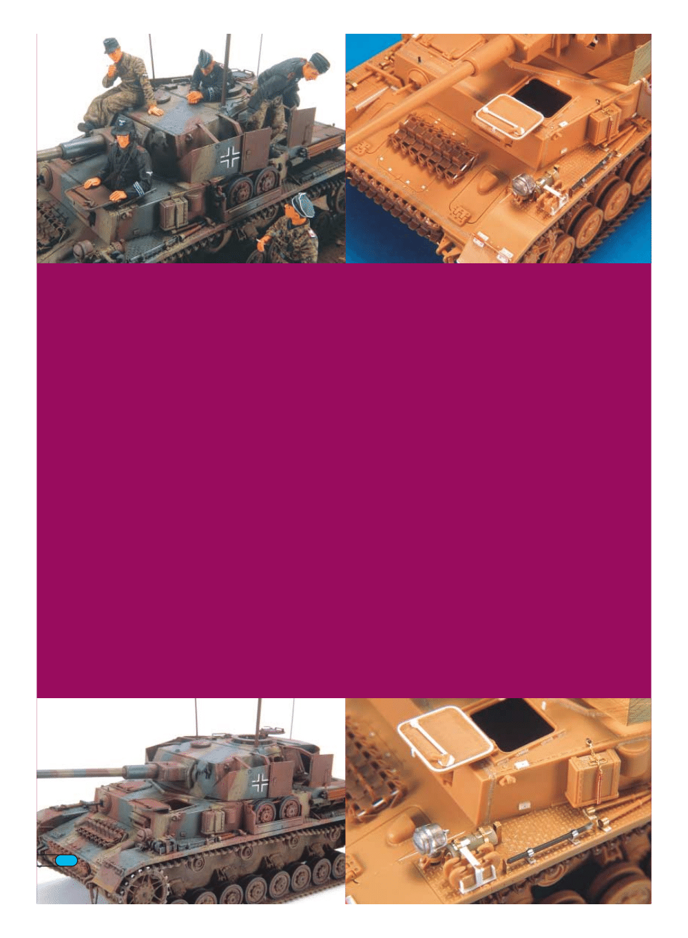
The Vignette
The figures are all Warriors resin products. The vehicle
commander and the driver are from the Waffen SS Panzer Crew
#1 (35030) set but with their positions reversed. I used a resin
head from Verlinden (I think) on the commander and a different
Warriors head on the driver. The gunner and radio operator are
from their Waffen SS Panzer Crew #2 (35031) set. I modified the
trousers on the radio operator sitting on the turret roof as they
were sculpted to represent some sort of coveralls. Standing on
the ground is the Waffen SS Tanker With Map (35038) built right
from the box without modification except for two seams in the
back of his jacket that were added.
I primed them with Tamiya XF2 Flat White and sprayed the faces
and hands with XF15 Flat Flesh. The flesh areas were further
treated by applying a coat of burnt sienna tinted with a bit of
white which was then wiped off with a small gun cleaning cloth,
which is as close to lint free as you will find. Uniforms were all
painted with various Humbrol enamels and oils. A light ‘pin wash’
of burnt umber oil paint was applied and the figures drybrushed
to highlight the raised details. Faced for the first time with having
to actually paint a map, I was forced to ask myself what they
really did look like? It turns out they don’t much look like the
printed maps you get from Verlinden and others. Fortunately,
Ron Volstad has an authentic 1943 German map which is printed
on a sepia tone paper with black lines for the roads and
contours, blue lines for the rivers and streams and green outlines
for woods and forested areas.
The base is an old 6” x 9” walnut wall plaque award that I
salvaged from work. I started off by masking off the lower edges
with masking tape before applying the groundwork. The
groundwork was made with hydrostone plaster compound mixed
with some sand and model railroad ballast along with a
generous dollop of burnt umber acrylic paint for color. The
verges were slightly built up by adding more of the mixture in
these areas. An old toy motorcycle wheel was used to provide
the track impressions in the road surface.
After this was completely dry, the surface was brush painted with
a coat of Tamiya XF52 Flat Earth acrylic paint and then
drybrushed with Humbrol SW4 (no longer available) mixed with a
bit of white artists oil paint. The grass is green garden twine cut
into short pieces and glued with white glue to the base. After the
glue had dried, the pieces were teased out with a pair of
tweezers and all loose strands removed to produce a fairly
realistic looking tall grass.
The wooden power pole is an Elefant product and the road
monument is from a Plus Model set I picked up at a small hobby
shop in Lucerne, Switzerland. The military signs on the pole are
from the Verlinden Normandy set. Hudson and Allen Forest Litter
was sprinkled around the sides of the road to impart an ‘autumn’
look to the base. The final touch was to add a title plate made
from black art board with Letraset lettering.
All in all, I was quite satisfied with the end result. The information
contained in the Osprey New Vanguard book allowed me to try a
unique camouflage scheme seldom seen on models of the
Pz.Kpfw.IV.
Wyszukiwarka
Podobne podstrony:
OD33 Panzer IV vs Char B1 Bis France 1940
Achtung Panzer 012 112 124 (PzKpfw IV)
Achtung Panzer 013 125 132 (Jagdpanzer IV)
Achtung Panzer 007 61 76 (StuG III IV)
wyklad IV
Mała chirurgia II Sem IV MOD
Temat IV 2 2
Pr UE Zródła prawa (IV 2013)
IV lek leczenie wspomagające w onkologii Żywienie
IV NIPiP Zmiany w podsystemie
IV 1 2 Atrybuty Osobow
BIOMATERIALY IV 2010
Zarządzanie skrzynką pocztową IV
Prezentacja wykłady I IV
1 Budownictwo ogólne sem IV
Wykład IV Model Portera
więcej podobnych podstron